Abstract
The dynamic control of an active magnetic bearing (AMB) rotor after the rotor falls to its touch-down bearings has always been a difficult problem for applications such as flywheel energy storage. The rotor drop process has obvious nonlinear dynamic characteristics. This paper first discusses the structure of AMBs and the basic principles of their control. Starting from the electromagnetic forces that electromagnets can provide, the problem is simplified to the influence of an electromagnetic force with constant damping characteristics on the dynamic characteristics of a dropped rotor. A dynamic model of an AMB rotor with touch-down bearings was built and the contact force model between the rotor and the touch-down bearings was determined. A constant damping electromagnetic force was applied in two ways to verify the dynamic control feasibility of a dropped rotor through magnetic bearings. The simulation results show that the dropped rotor recovery control is feasible by applying a reasonable electromagnetic force.
1. Introduction
As high-performance bearings, active magnetic bearings achieve stable support for rotors through electromagnetic force. They do not come into contact with the rotor surface during normal operation, so they have a series of advantages such as no wear, being oil-free, low energy consumption, low bearing housing vibration, dynamic control, and so on. They are attractive for flywheel energy storage applications [1,2]. Due to factors such as dynamic instability, bearing overload, and the partial failure of an electronic system, active magnetic bearings will lose effective control of rotor vibration. The rotor will fall on touch-down bearings with stronger load-bearing capacity to avoid falling directly on the magnetic bearing and causing damage to the system. This problem is particularly acute for large flywheel rotors.
Many scholars have conducted a lot of theoretical research on the dynamics of a rotor falling on touch-down bearings. In terms of modeling methods, Muszynska established a single-plane rotor model [3]; Ishii [4], CAO [5], and others established segmented rotor models; and Zhu Changsheng [6] and Antti [7] used the finite element method to model the rotor. In terms of bearing structure design, Zhu Yili et al. [8] designed a double-layer touch-down bearing and a self-eliminating gap touch-down bearing, and Yu Chengtao et al. [9] proposed a radial and axial integrated touch-down bearing that could eliminate the radial and axial gaps between the rotor and the touch-down bearing after a fall, thus protecting the system. In terms of structural parameter research, the impact of stiffness, damping, and friction factor on the drop response results has been studied [1]. Current research is mainly focused on modeling methods, parameter response effects, and new bearing designs.
Some scholars have also studied the design of the drop recovery controller to suppress the whirl of the rotor on touch-down bearings [10,11]. These studies focus on the drop response of the rotor under different magnetic bearing control strategies or influencing rotor whirl using active touch-down bearings.
In the event of a drop failure, if the magnetic bearing system is still functioning properly, it is very attractive to use the magnetic bearings to restore the normal suspension of the rotor. Even if suspension cannot be restored quickly, reducing the impact intensity of a drop through magnetic bearing control is also very meaningful for enhancing system reliability. When a drop occurs, how to make good use of the limited electromagnetic force to achieve the optimal dynamic control effect deserves in-depth study.
In order to achieve suspension recovery after a drop, it is necessary to study whether the electromagnetic force of magnetic bearings can effectively suppress the whirl motion of the rotor on touch-down bearings after a drop.
First, the structure of AMBs and the basic principles of their control were introduced. Starting from the electromagnetic forces that electromagnets could provide, the problem was simplified to the influence of an electromagnetic force with constant damping characteristics on the dynamic characteristics of a dropped rotor.
Based on Ishii’s simplified rotor-protection bearing model [4], a dynamic model of an AMB rotor with touch-down bearings was built and the contact force model between the rotor and the touch-down bearings was determined. The dynamic equations established were numerically simulated by the Runge–Kutta algorithm. Based on the model, a constant damping electromagnetic force was applied in two ways to verify the dynamic control feasibility of a dropped rotor through magnetic bearings. The simulation results show that the dropped rotor recovery control method is feasible when applying a reasonable electromagnetic force.
This paper only introduces a preliminary study on the recontrol evaluation of a magnetic bearing rotor falling on touch-down bearings. As a start, this research was carried out based on a simplified model. Rotor flexible modes, gyroscopic effects, etc., were not considered in the model and no relevant experimental verification was carried out. But this preliminary study is still instructive for exploring the positive role that magnetic bearings may play in the process of rotor dropping. The establishment of more complex models and related experimental verification work are to be carried out in the future.
2. Dynamic Equations for the Coupling System of the Touch-Down Bearings and the Rotor
2.1. Rotor System Structure
A typical AMB system includes a rotor, touch-down bearings, radial AMB stators, an axial AMB stator, a motor stator, an invertor, an AMB controller, etc. Its structure is shown in Figure 1.
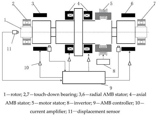
Figure 1.
AMB rotor system.
In order to simplify the problem, when studying the dynamic process of rotor dropping, only three parts of the rotor, the touch-down bearings, and the touch-down bearing housing are considered, and a simplified touch-down bearing-rotor system is obtained. The single-disc rotor model is used for system modeling, which is simple to model, convenient to calculate, and sufficient to reveal the core characteristics of dynamic processes. In addition, the touch-down bearing structure model is composed of an inner and outer two-layer structure, where the inner ring of the bearing directly bears the high-speed dropped rotor, and the outer ring of the bearing contacts the mechanical base.
The simplified model of the touch-down bearing rotor system during the process of rotor dropping is shown in Figure 2 below. Several assumptions are proposed when establishing the equation of the touch-down bearing rotor system considering the actual working conditions: (1) the relationship between the core shaft and the disc is described using a mass spring damping model, and each is subjected to mass concentration processing; (2) the rotor and the inner and outer rings of the touch-down bearing only consider three degrees of freedom in a plane perpendicular to the axial axes, that is, two translational motions in the plane and one rotation around the rotation axis; (3) the touch-down bearing housing is fixed to the base and has no vibration displacement; and (4) the connection between the inner and outer rings, as well as between the outer ring and the base, is a spring damping connection.
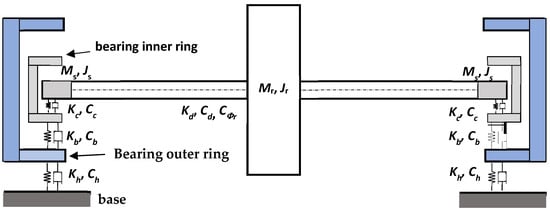
Figure 2.
Simplified model of the touch-down bearing rotor system.
The touch-down bearing rotor system in Figure 2 has a highly symmetrical feature on both sides. Therefore, the system model is further simplified as a single-plane touch-down bearing rotor motion model, as shown in Figure 3. rb is the inner radius of the touch-down bearing, Ob is the touch-down bearing center, rs is the radius of the rotor, and Os is the rotor center.
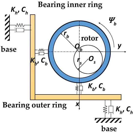
Figure 3.
Single-plane touch-down bearing rotor motion model.
The contact dynamic model between the core shaft and the touch-down bearing is shown in Figure 4. N is the contact force between the core shaft and the touch-down bearing, and δ is the contact deformation.
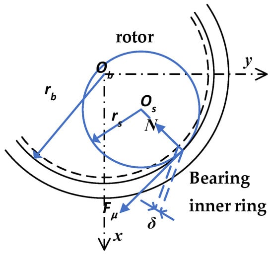
Figure 4.
Contact dynamic model between the core shaft and the touch-down bearing.
2.2. Dynamics Equation of Rotor System
Using the model shown in Figure 4, when the magnetic bearing fails, the rotor falls onto the touch-down bearing. The contact process between the core shaft and the touch-down bearing can be modeled using a Hertz contact model [1]. The relationship for the contact deformation and the contact force between the core shaft and the touch-down bearing is as follows:
At the contact point, if the linear velocity of the core shaft and that of the inner edge of the touch-down bearing are different, the contact between them will generate friction. Using the Coulomb friction model, the relationship between the relative motion speed of the contact points and the friction force is as follows (where vsc is the speed of the spindle at the contact point, and vbc is the relative speed of the inner edge of the touch-down bearing at the contact point):
The motion equations of each part of the system are shown below, and the meanings of each physical quantity in the equations and the parameter values used are shown in Table 1.

Table 1.
Model parameter values used.
For a rotor in normal operation, its orbit is very small compared to the gap between the touch-down bearing and the rotor. So, the impact of the rotor drop point is ignored here. It is considered that the initial position of the rotor is the center of the touch-down bearing, and the rotor rotates and falls from the initial position. The fourth-order Runge–Kutta algorithm was used to solve the response of the rotor after falling. MATLAB 2021b numerical solution tools were used to obtain the solutions of the dynamic equations.
3. Calculation Results of Drop Response without AMB Control
To verify the effectiveness of the dynamic model and the solving process, it was assumed that the rotor fell freely during operation, and the dynamic response of the rotor drop was calculated.
Based on the motion equation of the touch-down bearing rotor system provided in the previous text, a numerical simulation was conducted using MATLAB combined with the fourth-order Runge–Kutta method, with a time step of 1 us and a simulation calculation time of 5 s. It was assumed that the rotor was in a stable state before falling, the rotor had an initial rotational speed of 1000 rad/s, the initial position and translational initial speed of the rotor were both zero, and the touch-down bearing was initially completely stationary.
After the AMB was unable to continue providing support to the rotor due to certain reasons, the rotor fell under the action of gravity. Due to the deviation between the disk mass center and the disk geometric center, the unbalanced centrifugal force caused the falling trajectory of the rotor to not be a straight line, until the rotor and the inner ring of the touch-down bearing came into contact and caused rub-impact. During the contact process between the shaft and the touch-down bearing, due to the difference in tangential velocity at their contact points, it can be inferred from Coulomb friction theory that tangential friction will occur, and the shaft will undergo tangential motion under the action of friction. The touch-down bearing has three degrees of freedom, and under the combined action of the radial contact force and friction force, the inner bearing ring undergoes x-y direction translation and rotation around the shaft center. The speed difference between the inner ring and the shaft at the contact point will become smaller and smaller. When their speeds are completely equal, theoretically, the sliding friction will turn into static friction.
There are four typical forms of rotor drop response, as shown in Figure 5. The forward whirl motion requires forward force exerted by magnetic bearings or other parts of the system, which will not be discussed here.
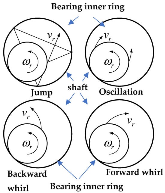
Figure 5.
Four typical forms of rotor dropping response.
From the perspective of touch-down bearing parameters, the factors that affect the corresponding form of dropping include the friction coefficient, support stiffness, damping, etc. Among them, touch-down bearing support damping is an important factor. By adjusting the support damping, different drop results can be calculated using the model established earlier.
The drop trajectory and the interaction force curve in Figure 6, Figure 7 and Figure 8 are the results of a numerical simulation based on the previous dynamic equations and the parameters in Table 1. The simulation results of the oscillation motion trajectory are shown in Figure 6a and the corresponding radial force curve is shown in Figure 6b. The simulation results of the jump motion trajectory are shown in Figure 7a and the corresponding radial force curve is shown in Figure 7b. The simulation results of the backward whirl motion trajectory are shown in Figure 8a and the corresponding radial force curve is shown in Figure 8b. The red circles in the trajectory figures correspond to the range of the rotor motion restricted by the touch-down bearing. The circle radius of 0.0002 m corresponds to the gap between the rotor and the touch-down bearing inner ring when the rotor is suspended in the equilibrium position.
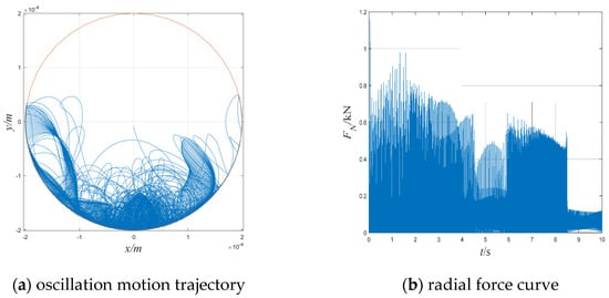
Figure 6.
Simulation results of the oscillation motion trajectory and the corresponding radial force curve.
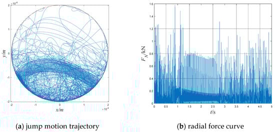
Figure 7.
Simulation results of the jump motion trajectory and the corresponding radial force curve.
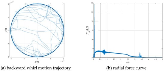
Figure 8.
Simulation results of the backward whirl motion trajectory and the corresponding radial force curve.
When the translational energy accumulated by the contact force on the rotor is small, the rotor undergoes several bounces under the viscous effect of the damping force, and then oscillates at the bottom of the touch-down bearing. The calculated radial force result shows that after several large impacts, the value fluctuates up and down under gravity, as shown in Figure 6.
When the contact force accumulates a large amount of translational energy for the rotor, the viscous effect of the damping force is relatively weak, and the rotor can generate multiple disordered jumps. The radial force exhibits discontinuous large impacts, and the maximum value of the radial force is greater than the oscillation form, as shown in Figure 7.
When the contact force accumulates enough translational energy for the rotor, the rotor will rotate backward along the inner ring of the touch-down bearing opposite to the direction of rotation. When the contact point between the rotor and the touch-down bearing remains unchanged, the friction direction is consistent with the motion direction, accelerating the rotor’s backward whirl. Due to the centrifugal force, the radius of the backward whirl continues to increase, resulting in an increase in the radial force. The backward whirl radius of the rotor has a maximum value, and after reaching the maximum value, due to the damping force, the system energy is continuously dissipated, the radius of rotation is continuously reduced, and the radial force is also continuously reduced. The trajectory and the force of the backward whirl form are shown in Figure 8.
From the trajectory and radial force results of the typical results of the three drop simulations, the rotor and the touch-down bearing are in continuous contact during the backward whirl process, and the interaction force in this process is very large, which can easily cause continuous damage to the system.
When the magnetic bearing rotor falls on the touch-down bearing, no active control is applied, and the probability of damage caused by a transient impact with the touch-down bearing can be reduced to a certain extent through the adjustment of the structural parameters of the touch-down bearing; however, this reduction has limitations. In the event that the rotor speed rises, the rotor mass increases, etc., the impact effect of the falling rotor will increase, and even if the touch-down bearing structure is adjusted, after a long interaction time, the rotor journal may be damaged during the interaction with the touch-down bearing. Therefore, it is necessary to carry out research on rotor fall dynamic control, and it is expected that the magnetic bearing will exert active control force on the falling rotor, intervene in the drop dynamic behavior, and reduce the damage caused by the rotor falling into the system.
To control the dynamic behavior of a high-speed rotor after a fall by means of magnetic bearings, first, it is necessary to evaluate whether the electromagnetic force provided by a conventional magnetic bearing design is sufficient to affect the drop dynamics.
4. Recontrol of a Dropped AMB Rotor
Since the rotor drop will cause destructive consequences, when the fall occurs and the magnetic bearing can still output electromagnetic force normally, it is naturally hoped that the dynamic behavior of the high-speed rotor after the fall can be controlled through the magnetic bearing, effectively reduce the interaction force between the fallen rotor and the touch-down bearing, and even break away from the falling state and achieve recontrol of the magnetic bearing rotor.
4.1. Magnetic Bearing Control Principle
The electromagnetic force on a single degree of freedom of a magnetic bearing is usually provided by a pair of electromagnets, and the two magnets work differentially to provide the resultant force in both positive and negative directions, and its working principle is shown in Figure 9. Multi-DOF magnetic bearings are composed of multiple pairs of single-DOF magnetic bearings. In the figure, i0 is a constant bias current and it is a positive value, ix is a control current and its absolute value is less than i0, x is the offset of the rotor from the equilibrium position, m is the rotor mass, and fx is the net force acting on the rotor, as shown in Equation (14). The k in the equation is a constant related to the parameters of the electromagnet and the rotor. The s0 is the AMB air gap.
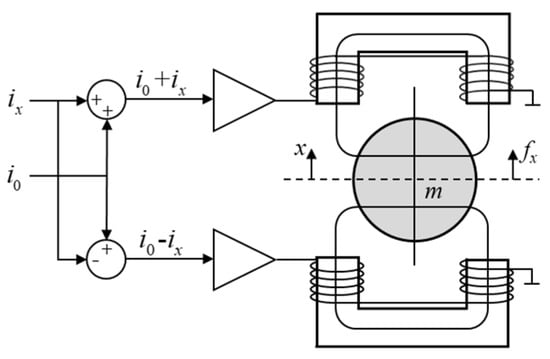
Figure 9.
Working principle of an AMB.
When the rotor displacement and the coil currents vary within a small neighborhood of their static values, the equation can be linearized at x0 and i0. The linearized equation is as follows. ki and ks are the force–current coefficient and force–displacement coefficient, respectively.
A magnetic bearing requires closed-loop feedback control to stabilize an AMB rotor system, and when the rotor is offset from the equilibrium point, the magnetic bearing needs to provide the rotor with a mechanical spring-like restoring force to adjust the rotor back to the equilibrium position. In addition, in order to attenuate the rotor vibration energy, the force supplied by the AMB must also include a damping component. The simplest way is to divide the AMB force into two parts: damping and stiffness:
where P is the stiffness coefficient and D is the damping coefficient. The expression of the control current ix can be obtained by combining Equations (15) and (16):
In this case, the control current is a linear combination of proportional feedback and differential feedback for the displacement, that is, the controller is a classic PD controller.
4.2. Electromagnetic Control Force Application Strategy
The rotor is in severe oscillation after the fall, and it is necessary to evaluate whether magnetic bearings designed based on normal operating conditions can have a strong influence on the rotor’s movement. For this reason, it is necessary to consider whether an optimal method of applying electromagnetic force can be found.
As discussed earlier, the electromagnetic force of a magnetic bearing can be broken down into stiffness and damping components. Since the stiffness provided by magnetic bearings is small relative to the contact stiffness between the rotor and the inner ring of the touch-down bearing, converting the electromagnetic force into a pure damping force helps to better attenuate the vibrational energy of the falling rotor. Then, the expected electromagnetic force is expressed as:
Due to the limited bearing capacity, in order to attenuate the kinetic energy of the rotor as soon as possible after the fall, the optimal method involves the electromagnet always outputting electromagnetic force at its maximum load capacity in the opposite direction to the direction of the rotor’s movement or whirl. If the maximum electromagnetic force is defined as fm, fx in Equation (18) becomes the constant fm. The equivalent D parameter in Equation (18) is one that varies with the amount of velocity.
In order to attenuate the rotor kinetic energy as quickly as possible, a constant-magnitude maximum electromagnetic force fm is used. There are two ways in which fm can be applied. One is that the fm direction is the opposite direction to the rotor’s velocity direction, and the other that it is opposite to the rotor’s whirl direction.
When the constant-magnitude electromagnetic force fm acts on the rotor, when its direction is in the opposite direction to the rotor’s velocity, its effect is a pure velocity damping force. When the coordinates are defined as shown in Figure 10, fm can be decomposed into components in the x and y directions, which are fx and fy, respectively. The force expression is as follows:
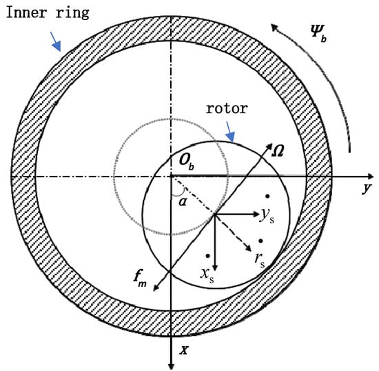
Figure 10.
The coordinates defined.
After a drop occurs, the most dangerous mode of movement of the rotor is a backward whirl. The backward whirl component in the rotor motion component can be simplified to the circular whirl of a single-frequency component, and the direct control of the backward whirl can not only solve the most critical problem in the process of drop dynamics, but also simplify the control behavior. So, when the rotor undergoes a whirling motion as shown in the figure below, the ideal electromagnetic control force direction can be selected to be opposite to the whirl direction. In this way, its effect is a pure whirl damping force. In Figure 10, the whirl velocity of the rotor around the inner ring of the bearing is denoted as Ω. The following relationship can be obtained.
The following can be deduced.
The expression for the electromagnetic force in the form of pure whirl damping is:
4.3. Electromagnetic Force Control Results
When no electromagnetic control force is applied, the rotor trajectory and the interaction force curve in Figure 6, Figure 7 and Figure 8 are obtained by numerical simulation based on the previous dynamic equations and the parameters in Table 1.
The rotor drops at a high speed of 1000 rad/s and will first collide with the inner ring of the touch-down bearing. A radial contact force is generated during the collision, with a maximum radial force of 11.78 kN. After several collisions, the rotor enters a whirl state around the inner ring of the touch-down bearing. When the whirl energy of the rotor is continuously dissipated under the action of friction and damping force, the rotor will not be able to maintain a full circumferential whirl, and the rotor will enter the bounce state. As the rotor’s energy continues to dissipate, it oscillates back and forth at the bottom of the inner ring of the touch-down bearing, maintaining contact with the inner ring of the bearing. The force value fluctuates around the value of the rotor’s gravity, and after a long enough period of time, the rotor stops vibrating.
From the perspective of the amplitude of the impact force, the maximum radial force of the whole drop process is 11.78 kN. From the perspective of the cumulative effect, the average force of the whole simulation process (0–5 s) is 562.51 N.
The effect of the applied constant-magnitude electromagnetic force on the drop dynamics is studied below. As mentioned earlier, there are two ways to apply. But first, it is necessary to determine the achievable magnitude of this constant force in engineering applications. Considering the conventional design, the AMB rotor radius is close to Rb, the inner ring radius of the touch-down bearing, the AMB rotor profile is taken as a square. Then, the AMB rotor profile area is approximately 2.25 cm2. The load of this AMB can be estimated as 2.25 cm2 × 32 N/cm2 = 72 N [1]. The magnitude of the applied electromagnetic force can be set to 40 N for the numerical simulation.
Given that the magnitude of the electromagnetic force is 40 N, and the direction of the force is always opposite to the direction of the rotor velocity, the simulation results are shown in Figure 11. The motion trajectory of the rotor are shown in Figure 11a and the corresponding radial force curve is shown in Figure 11b.
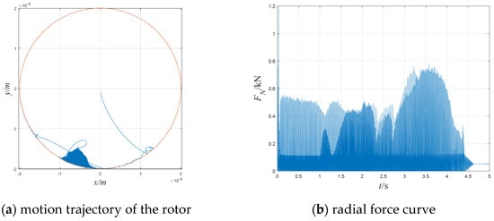
Figure 11.
Drop simulation with velocity damping.
As can be seen from the figure, under the speed damping mode, applying a constant electromagnetic force of 40 N can make the rotor stop undergoing a backward whirl movement and cause it to only move in the lower half-circle of the touch-down bearing, so that the maximum radial force in the contact between the rotor and the touch-down bearing is greatly reduced to 1193 N. The average radial force also significantly decreases to 54.61 N.
When the whirl damping mode is used, the phenomenon is similar, and the backward whirl disappears and the rotor only moves in the lower half-circle of the touch-down bearing as shown in Figure 12. The maximum radial force in the contact between the rotor and the touch-down bearing is 1490 N. The average radial force also significantly decreases to 52.20 N.
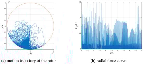
Figure 12.
Drop simulation with whirl damping.
According to the simulation results, the maximum force impact and cumulative damage effect of the drop process are greatly weakened when the electromagnetic control force is applied in either of these two ways.
Comparatively speaking, under the condition of applying speed damping, the rotor has almost stopped bouncing at about 4.6 s, and enters a slight oscillation state at the bottom of the protective bearing until it stops. With the whirl damping applied, the rotor remains bouncing at the end of the simulation and will continue for a period of time. From the perspective of energy dissipation, applying velocity damping is more effective for system vibration energy dissipation. However, the whirl damping mode does not need to achieve the real-time velocity of the rotor, and only needs to achieve the angular velocity of the rotor whirl velocity, which is easier to achieve in engineering applications.
We adjusted the magnitude of the electromagnetic force fm, and continued to simulate and study the influence of the magnitude of the electromagnetic force on the dynamic behavior under the two electromagnetic force application methods. The numerical results are as follows.
As can be seen from Figure 13 and Figure 14, the application of an electromagnetic force greater than about 10 N can prevent the rotor from entering the backward whirl state after falling, resulting in a significant decrease in the maximum radial force and the average radial force. From this point of view, when the rotor falls, the magnetic bearing has the potential to prevent the rotor from entering a destructive whirl, thereby restoring the stable suspension of the rotor.
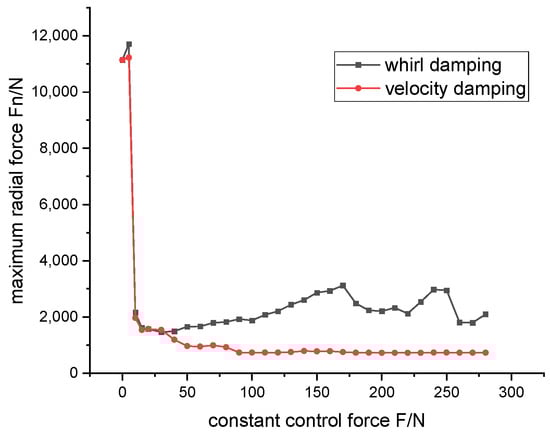
Figure 13.
Maximum radial force results when different control force amplitudes are applied.
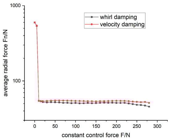
Figure 14.
Average radial force results when different control force amplitudes are applied.
5. Conclusions
Based on a simplified rotor-protection bearing model, a dynamic model of an AMB rotor with touch-down bearings was built and a contact force model between the rotor and the touch-down bearings was determined. Numerical simulations were carried out on the model to obtain the rotor trajectories belonging to the typical rotor drop response forms. The contact force on the rotor during a drop was calculated and analyzed. Considering the optimal use of the reasonable electromagnetic force that can be provided by an electromagnet, the influence of electromagnetic force with pure damping characteristics on the dynamic characteristics of the dropped rotor was studied. The constant electromagnetic damping force was applied in two ways to verify the dynamic control feasibility of the magnetic bearings for the dropped rotor. The simulation results show that the magnetic bearing has the potential to prevent the rotor from entering a destructive whirl, thereby restoring the stable suspension of the rotor.
Author Contributions
Conceptualization, K.Z. and Y.X.; methodology, K.Z. and Y.X.; software, K.Z. and Y.X.; validation, K.Z. and Y.X.; formal analysis, K.Z. and Y.X.; investigation, K.Z. and Y.X.; resources, K.Z. and Y.X.; data curation, K.Z. and Y.X.; writing—original draft preparation, K.Z.; writing—review and editing, K.Z.; visualization, K.Z. and Y.X.; supervision, K.Z.; project administration, K.Z.; funding acquisition, K.Z. and Y.X. All authors have read and agreed to the published version of the manuscript.
Funding
This research was funded by the National Key R&D Program of China, grant number 2023YFB2406400.
Data Availability Statement
The original contributions presented in the study are included in the article, further inquiries can be directed to the corresponding author.
Conflicts of Interest
The authors declare no conflict of interest.
References
- Maslen, E.H.; Schweitzer, G.; Bleuler, H.; Cole, M. Magnetic-Heory, Design, and Application to Rotating Machinery; Springer: Berlin/Heidelberg, German, 2009. [Google Scholar]
- Caprio, M.T.; Murphy, B.T.; Herbst, J.B. Spin commissioning and drop tests of a 130 kW-hr composite flywheel. In Proceedings of the Ninth International Symposium on Magnetic Bearings, Lexington, KA, USA, 3–6 August 2004. [Google Scholar]
- Muszynska, A. Rotordynamics, 1st ed.; CRC Press, Taylor & Francis Group: Boca Raton, FL, USA, 2005. [Google Scholar]
- Ishii, T.; Kirk, R.G. Transient response technique applied to active magnetic bearing machinery during rotor drop. J. Vib. Acoust. 1996, 118, 154–163. [Google Scholar] [CrossRef]
- Cao, J.; Allaire, P.P.; Dimond, T.; Klatt, C.; van Rensburg, J.J.J. Rotor drop analyses and auxiliary bearing system optimization for AMB supported rotor experimental validation-part I: Analysis method. In Proceedings of the 15th International Symposium on Magnetic Bearings, Kitakyushu, Japan, 3–6 August 2016. [Google Scholar]
- Zhu, C. Effect of backup bearing impact surface pairs on rotor dropping transient response after active magnetic bearing failure. J. Vib. Eng. 2010, 23, 475–479. (In Chinese) [Google Scholar]
- Antti, K.; Jussi, S.; Aki, M. Dynamic simulation of a flexible rotor during drop on retainer bearings. J. Sound Vib. 2007, 306, 601–617. [Google Scholar]
- Zhu, Y. Research on New Type Catcher Bearings in Active Magnetic Bearing System. Ph.D. Thesis, Nanjing University of Aeronautics and Astronautics, Nanjing, China, October 2013. (In Chinese). [Google Scholar]
- Yu, C.; Sun, Y.; Wang, H.; Shan, W.; Chen, Y.; Qiu, R. Dynamic analysis of magnetic bearing rotor dropping on radial and axial integrated auxiliary bearing. Mech. Mach. Theory 2019, 140, 622–640. [Google Scholar] [CrossRef]
- Sun, G.Y. Magnetic relevitation of flywheel rotor with high speed backward whirl. In Proceedings of the ASME 2012 International Mechanical Engineering Congress and Exposition, Houston, TX, USA, 9–15 November 2012. [Google Scholar]
- Cade, I.S.; Sahinkaya, M.N.; Burrows, C.R.; Keogh, P.S. On the design of an active auxiliary bearing for rotor/magnetic bearing systems. In Proceedings of the 15th International Symposium on Magnetic Bearings, Nara, Japan, 26–29 August 2008. [Google Scholar]
Disclaimer/Publisher’s Note: The statements, opinions and data contained in all publications are solely those of the individual author(s) and contributor(s) and not of MDPI and/or the editor(s). MDPI and/or the editor(s) disclaim responsibility for any injury to people or property resulting from any ideas, methods, instructions or products referred to in the content. |
© 2024 by the authors. Licensee MDPI, Basel, Switzerland. This article is an open access article distributed under the terms and conditions of the Creative Commons Attribution (CC BY) license (https://creativecommons.org/licenses/by/4.0/).