1. Introduction
Distributed energy storage (DES) means energy storage systems that are distributed throughout the power grids, typically located near the consumer ends [
1]. DES helps balance supply and demand (especially from renewable energy) in a more timely manner than centralized energy storage, thus improving overall grid reliability and resilience. Distributed energy storage is promising for microgrids. Two primary sources of small-scale distributed energy storage are stand-alone batteries and electric vehicles [
2].
Flywheel energy storage (FES) is an energy storage type with advantages in terms of its high power density, high round-trip efficiency (around 90%) [
3], long-lasting nature (typically 20 years or 20,000 cycles or more) [
4], cost-effectiveness in the long term, eco-friendliness, and ease of maintenance. It is a solution that can be used to mitigate the intermittent supply of wind power, and it has proven efficient in wind energy storage and power smoothing [
5,
6,
7,
8,
9]. However, FES is a viable [
10] but not well-suited candidate for distributed energy storage (DES) due to two main limitations.
One limitation is the energy storage capacity. The capacity of a single flywheel is limited by its physical characteristics and typically ranges from 3 kWh to 133 kWh [
11]. Thus, the total flywheel storage is limited if the number of flywheels is insignificant. If the capacity limit issue of the flywheel storage is addressed, the flywheel can even serve as a battery, providing backup power for a period.
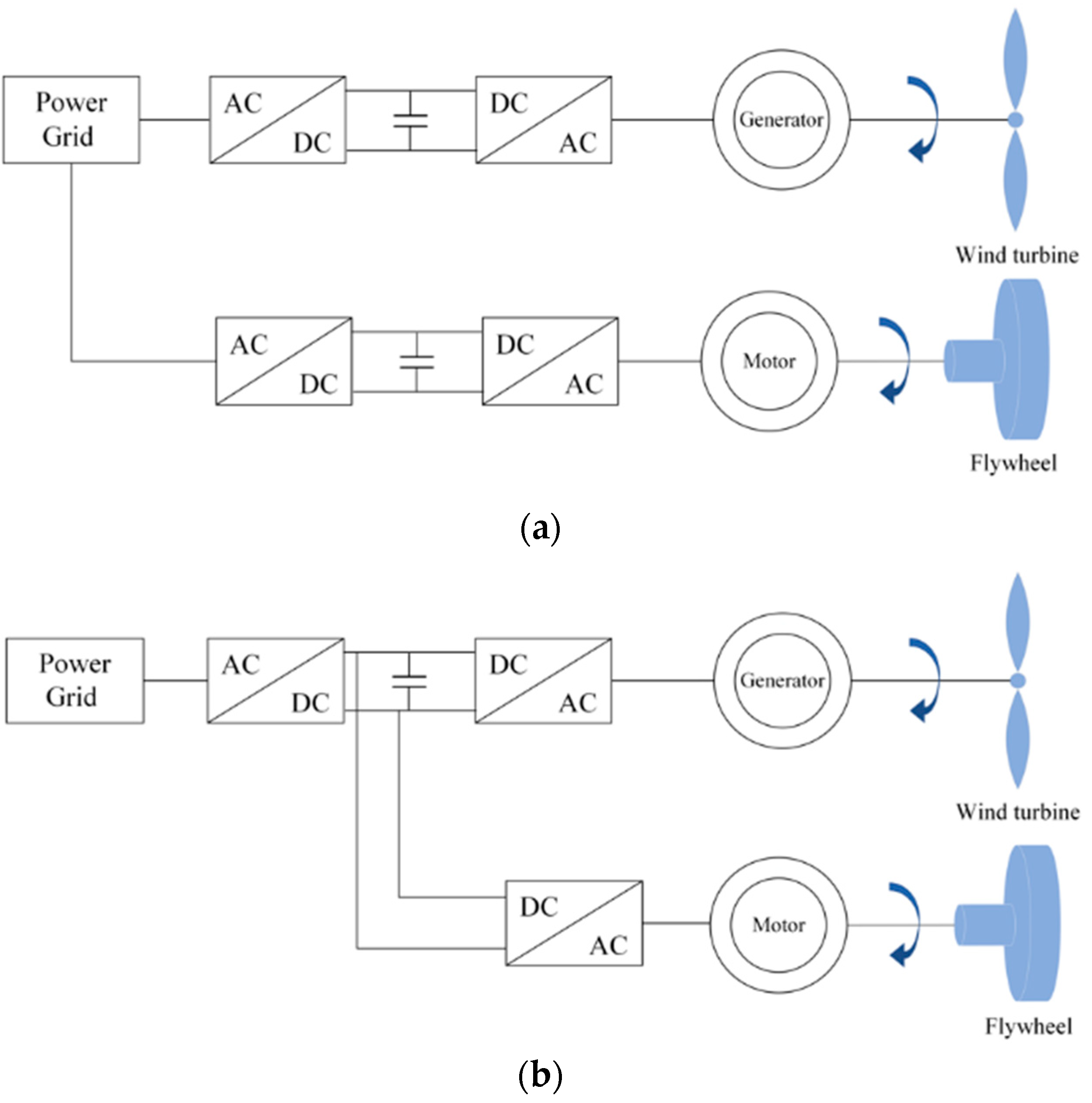
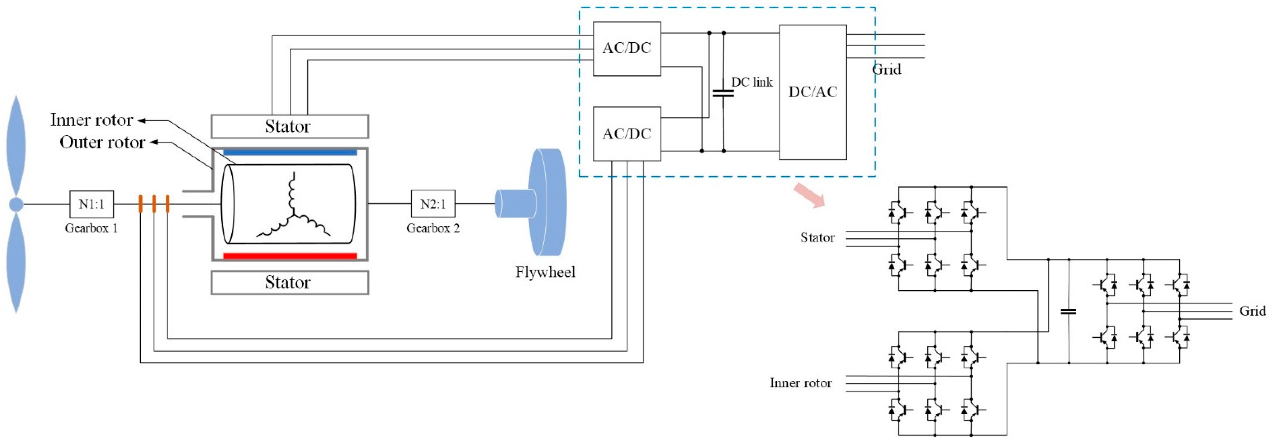
The second limitation concerns the flywheel’s connection to the wind turbine. When FES is integrated with wind power generation, there are two typical connection schemes [
12], grid connection and DC link connection, as shown in
Figure 1. No matter which connection is used, a drive motor is needed to drive the flywheel, and an electric converter (or multiple converters) is used for the motor. On the one hand, installing the motor and the converter(s) requires much space, so flywheels are typically placed on the ground rather than inside the nacelle. On the other hand, when power is transferred between the flywheel and the grid, it passes through the motor and converters, and each component causes losses during the power exchange process, thus reducing power efficiency. Therefore, equipping one flywheel unit for one wind turbine is not expedient, and FES is thus less modular and distributed than battery energy storage.
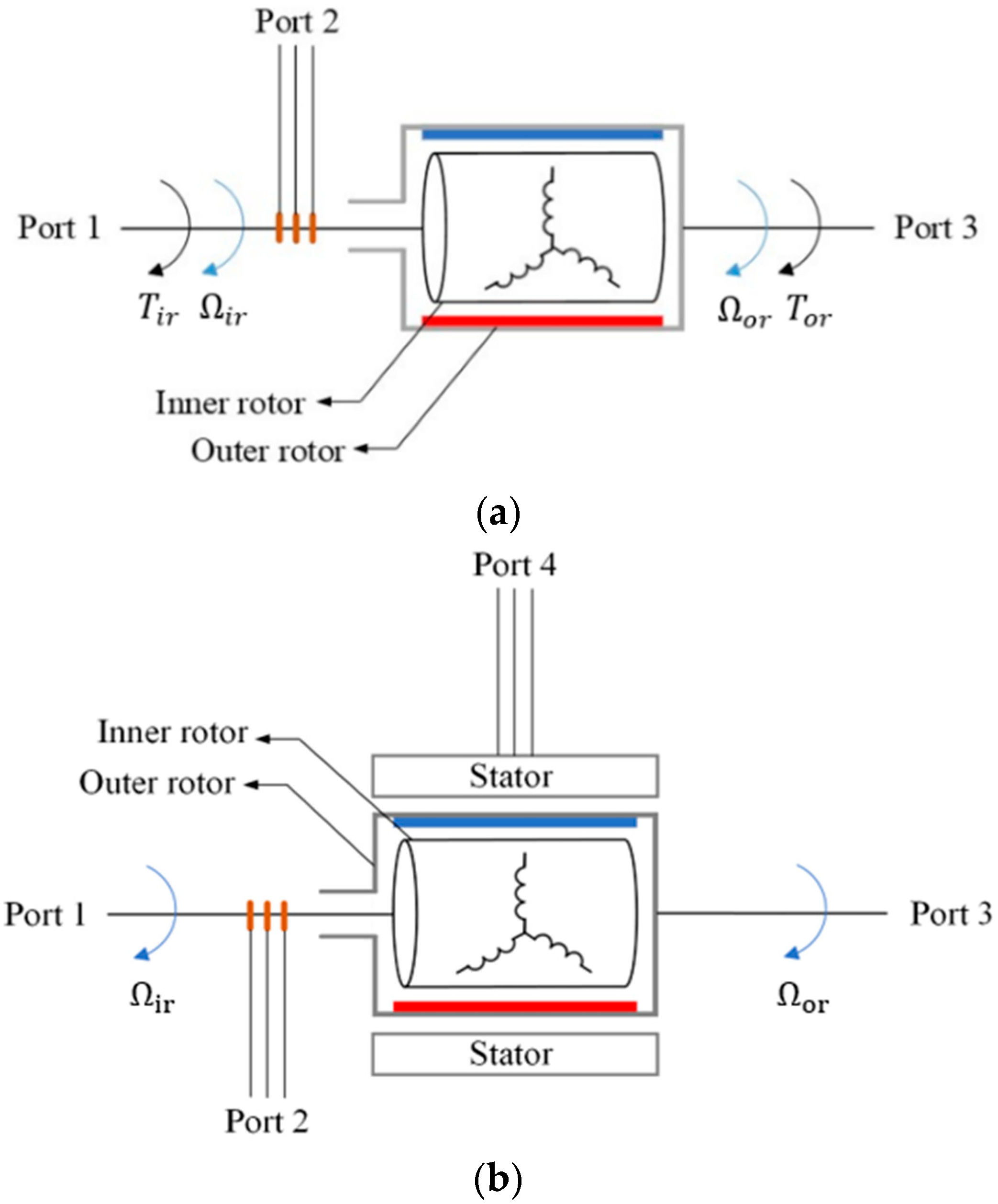
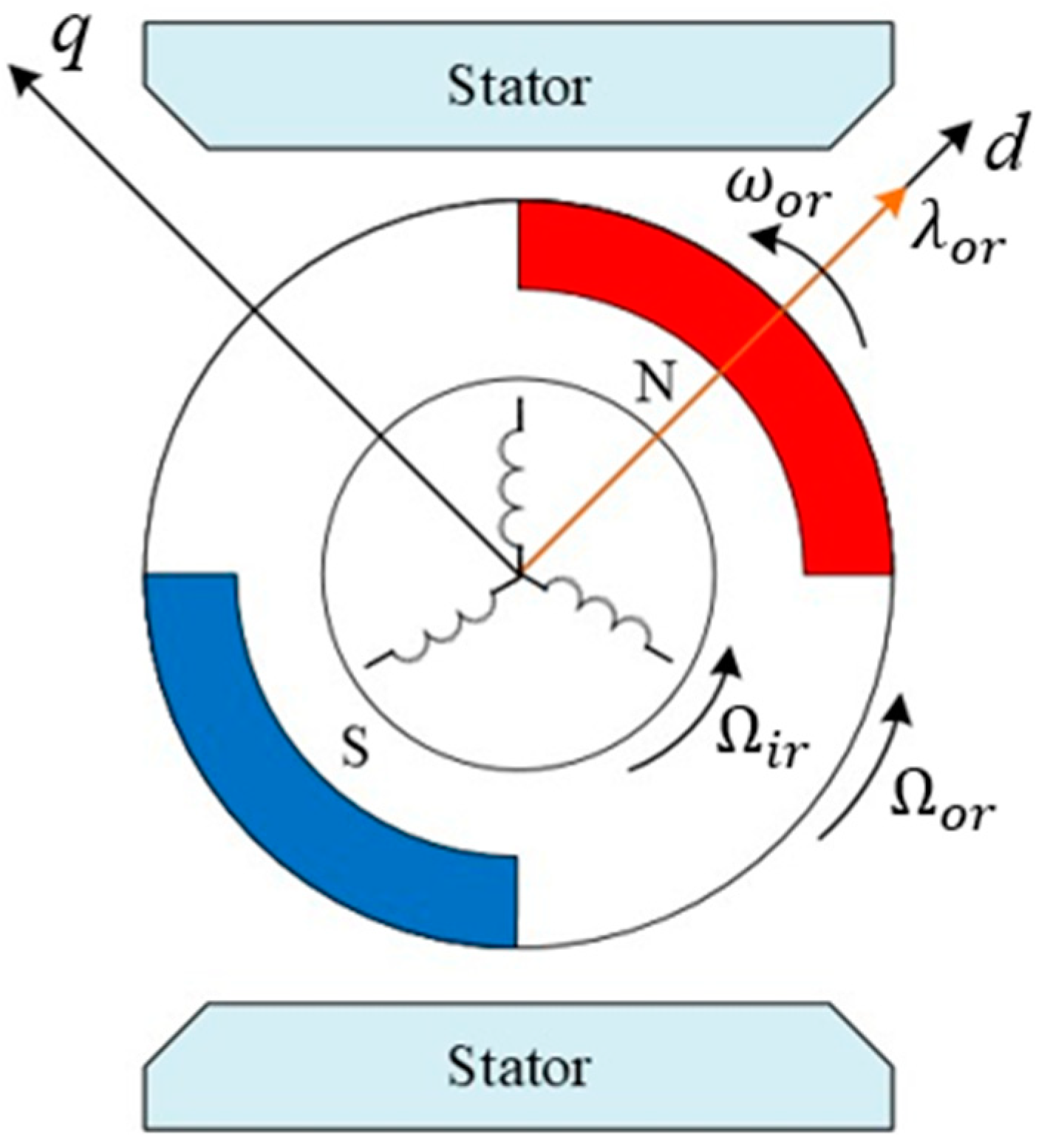
One solution is to use a dual-mechanical-port (DMP) generator. Unlike conventional electric machines, which feature one stator and one rotor, DMP machines have two rotors and do not necessarily have a stator. In 1994, M. Ehsani and S. Sodhi, at Texas A&M University, introduced a DMP machine consisting of only two rotors, named the “transmotor” [
13]. It is also called a two-member transmotor. The diagram of a transmotor is shown in
Figure 2a. Note that the red and blue bars in the inner rotor represent a permanent magnet’s north and south poles, respectively (the same applies to all the machine figures with a permanent magnet rotor). A transmotor signifies the active electromagnetic coupling of the two rotors, enabling mechanical power transfer directly between the two mechanical ports (Port 1 and Port 3) and the inner and outer rotor shafts, and the amount of the transferred mechanical power is decided by the electrical port (Port 2) and inner rotor windings [
13]. This structural innovation aims to enhance energy transfer efficiency. M. Ehsani also proposed a three-member transmotor variation, as shown in
Figure 2b. The three-member topology has a stator in addition to the two rotors, which provides more control degrees of freedom than the two-member topology, but its control becomes more complicated. Later, L. Xu, at Ohio State University, furthered the research on DMP machines and mainly focused on the three-member topology [
14,
15]. DMP machines have garnered more attention in recent years [
16,
17,
18].
Transmotors have possible applications in electric vehicles (EVs) and hybrid electric vehicles (HEVs), as they could be used to improve the overall performance of the vehicles [
19,
20,
21,
22,
23]. Papers [
21,
22,
23] by M. Ehsani, NF. Ershad, and RT. Mehrjardi explored different applications of transmotors in EVs or HEVs. Although the applications vary, the fundamental idea in these papers is to combine a two-member transmotor with a flywheel as a kinetic energy recovery system (KERS) to increase the compactness and efficiency of the powertrains. Additionally, the flywheel plays a role in alleviating the burden on the vehicle battery by efficiently storing and recovering kinetic energy during deceleration and braking, making the overall vehicle more energy-efficient and sustainable. DMP machines are rarely considered for wind power generation. In papers [
24,
25], a three-member DMP generator was used as a variable gearbox with a battery energy storage unit, and a second generator was required to connect to the power grid.
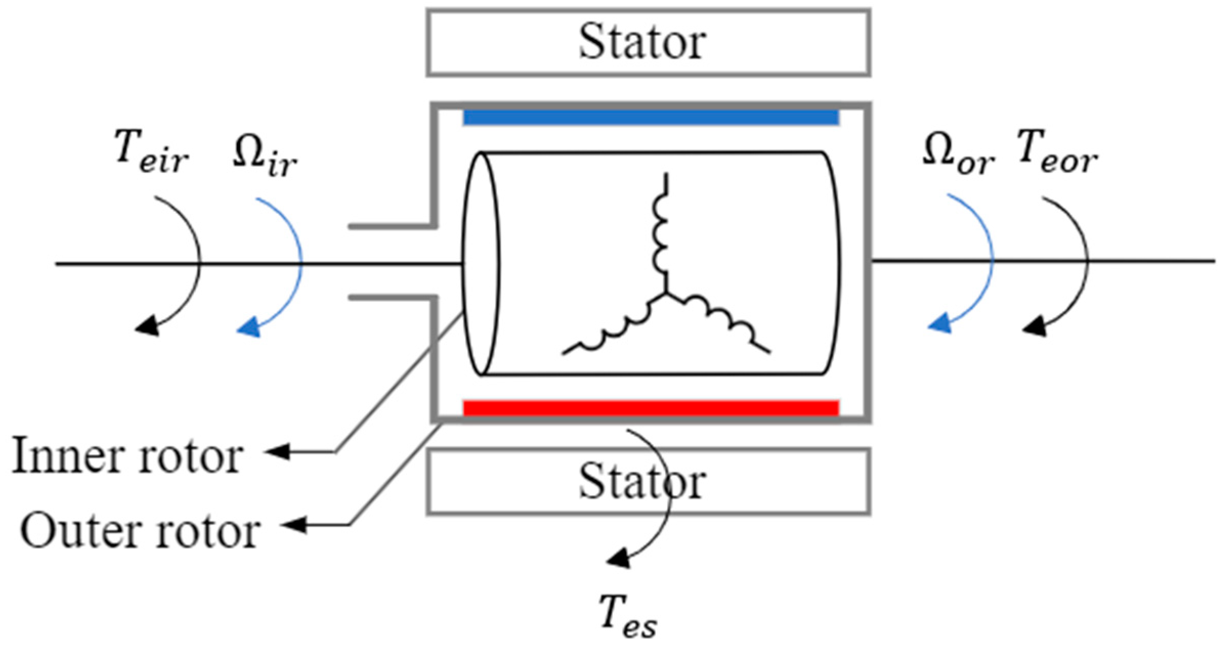
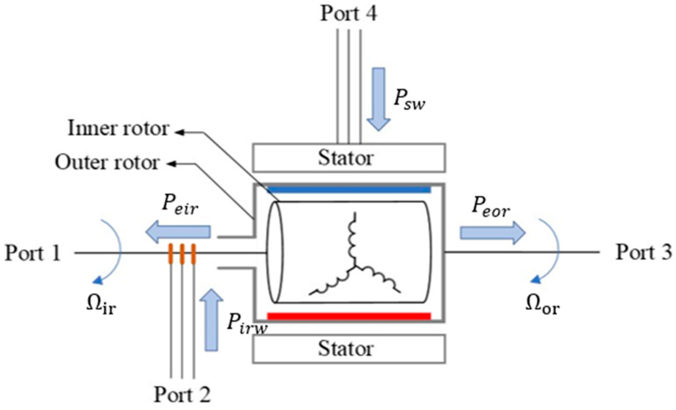
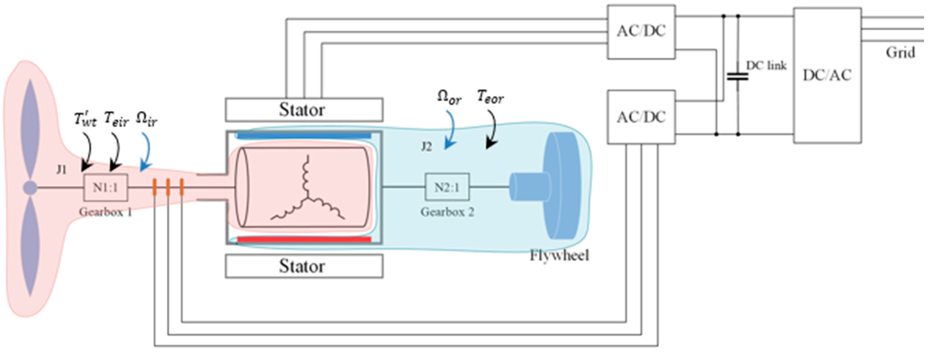
This paper proposes a “Three-member transgenerator–flywheel” system. Its configuration is shown in
Figure 3, in which the wound inner rotor is driven by the wind turbine, the permanent magnet (PM) outer rotor is connected to the flywheel, and the wound stator provides more control degrees of freedom and serves the critical function of achieving independent control of the two rotors for different purposes. This configuration offers several advantages:
- (1)
Compactness: The proposed configuration integrates the wind turbine and flywheel in one system, eliminating the drive motor and converters, making it possible to fit it into a turbine nacelle.
- (2)
Efficiency: The connection between the wind turbine and the flywheel, using the proposed configuration, creates a shorter path with fewer electrical components for power transfer, which reduces the total power losses and thus increases the overall power efficiency.
- (3)
Scalability: This configuration ensures one transgenerator is equipped with one flywheel in the wind turbine. The one-to-one feature enables a wind farm to achieve substantial energy storage when the wind turbine number is significant.
- (4)
Distribution: The one-to-one feature ensures flywheels are as distributed as the wind turbine units. This feature becomes more evident in a wind-based distributed generation (DG) system.
6. Conclusions and Future Work
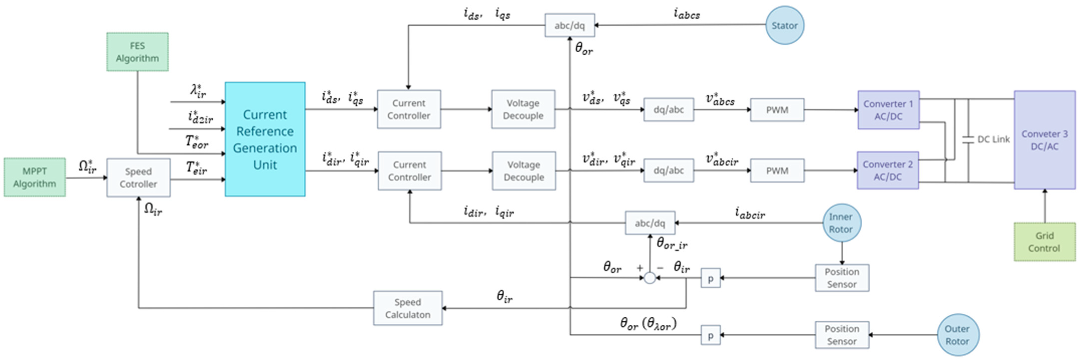
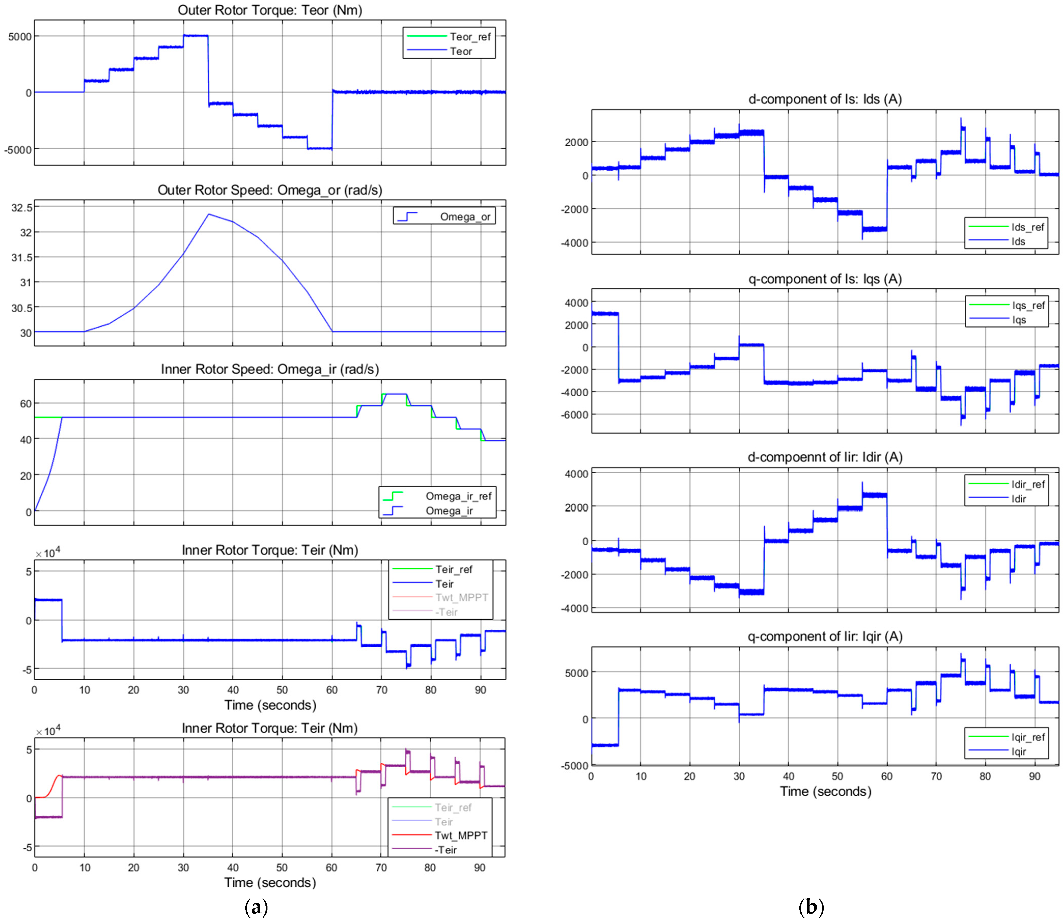
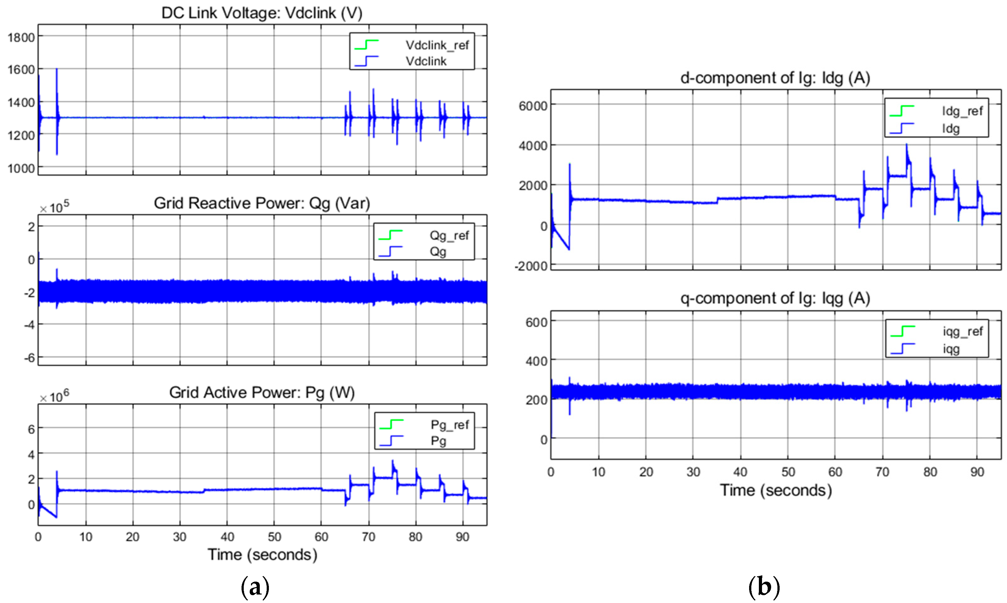
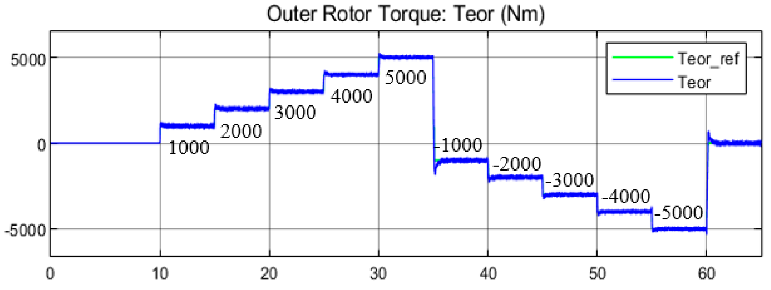
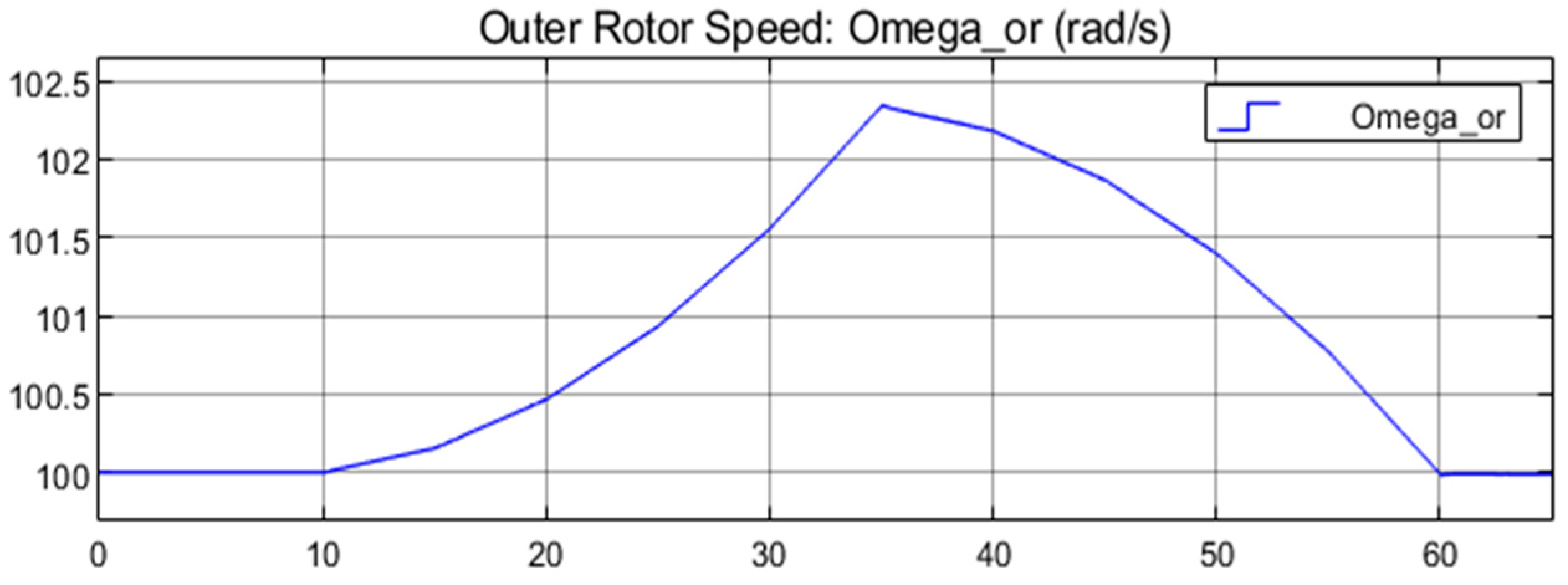
This paper presents a three-member transgenerator–flywheel system for wind power generation, which is a new flywheel energy storage (FES) concept that posits that the flywheel can be directly integrated with the wind turbine using a dual-mechanical-port (DMP) generator (transgenerator). This configuration makes the FES more modular and distributed than the conventional FES system. The system was illustrated by transgenerator (presented from the mathematical model and power flow), flywheel (presented from the principle, power characteristics in the transgenerator–flywheel system, energy management strategies, and flywheel selection considerations), and a control system. System modeling and simulations were conducted using Simulink. The first part of the simulation verified the accuracy and time response of the control over the two rotors with the outer and inner control loops. The control for both rotors had a quick and accurate response. The second part of the simulation evaluated the flywheel storage performance. The results showed that the flywheel had a maximum charging power of 27% of the wind turbine’s rated power at 80% SoC. The flywheel could rapidly and accurately respond to the power demand due to the excellent time response of the outer rotor torque control and its ability to maintain speed.
The aims of future work should include the following: (1) experimental validation of the proposed system to support the simulation results and further confirm its viability; (2) a demonstration of the FES energy management algorithm; (3) a comparative analysis of the transgenerator–flywheel storage system and conventional wind turbines (such as doubly fed induction generators, DFIGs, and permanent magnet synchronous generators, PMSGs) incorporating FES regarding storage capability, efficiency, and control; and (4) an analysis and comparison of how the performance of the transgenerator–flywheel system changes with different wind turbine sizes and its corresponding effects on the power grid.


