Abstract
The development of wind power has brought about increasing challenges in decommissioning, among which DWTBs (decommissioned wind turbine blades) are the most difficult component to deal with. To enable the cost-effective, energy-efficient, and environmentally friendly large-scale utilization of DWTBs, an experimental study on thermogravimetric and pyrolysis characteristics of DWTBs was carried out. A new process involving recycling glass fiber with pyrolysis gas re-combustion and flue gas recirculation as the pyrolysis medium was innovatively proposed, and the simulation calculation was carried out. Thermogravimetric experiments indicated that glass fiber reinforced composite (GFRC) was the main heat-generating part in the heat utilization process of blades, and the blade material could basically complete pyrolysis at 600 °C. As the heating rate increased, the formation temperature, peak concentration, and proportion of combustible gas in the pyrolysis gas also increased. The highest peak concentration of CO gas was observed, with CO2 and C3H6 reaching their peaks at 700 °C. The solid product obtained from pyrolysis at 600 °C could be oxidized at 550 °C for 40 min to obtain clean glass fiber. And the pyrolysis temperature increased with the increase in the proportion of recirculation flue gas. When the proportion of recirculation flue gas was 66%, the pyrolysis temperature could reach 600 °C, meeting the necessary pyrolysis temperature for wind turbine blade materials. The above research provided fundamental data support for further exploration on high-value-added recycling of DWTBs.
1. Introduction
With the swift advancement of the wind power industry, the issue of wind turbine decommissioning has become increasingly prominent [1,2,3,4]. The expected service life of wind turbines is 20–25 years [5,6,7], and due to the technical upgrades of wind power stations such as “replacing small ones with large ones”, some wind turbines over 15 years old will be decommissioned ahead of schedule. Among all components, the wind turbine blades pose the greatest challenge. It is predicted that the number of DWTBs will reach 500,000 tons/year in 2029, and with the rapid growth of installed capacity of wind turbines, the global DWTBs will reach 43.4 million tons in 2050 [8,9]. Improper handling of these blades could lead to land occupation and environmental pollution from heavy metals and organic substances. Hence, the recycling and treatment of DWTBs is urgent [10,11].
The prevalent wind turbine blades are glass fiber reinforced composites (GFRC), possessing traits of high strength, high stiffness, and cost-effectiveness, and accounting for more than 90% of the whole blade mass; the rest comprises core materials, adhesives, coatings, and metal lightning rods [12,13,14]. GFRC can be regarded as a composite material of resin and glass fiber. Resin serves as the matrix, balancing load and protecting glass fiber. Glass fiber, as a reinforcement material, enhances the overall mechanical properties. Since the resin in GFRC is a thermosetting resin, separating the matrix and reinforcing material through remelting is challenging [15,16]. Due to the extremely complex materials and manufacturing processes used in wind turbine blade manufacturing, managing a large quantity of DWTBs has become one of the major challenges of solid waste treatment in the wind power industry [17].
Development of treatment technologies for DWTBs has gained significant international attention [18]. Various processes, each with its advantages and limitations, are being explored. Landfill is the most common method to dispose of DWTBs, but it poses challenges such as land occupation and the release of toxic substances like styrene. Many countries have implemented regulations such as taxation, fines, or bans on DWTBs landfilling [19,20,21]. Mechanical treatment is a low-cost and simple way to realize the separation of glass fiber and resin. The products obtained by crushing and other means can be used as fillers in architecture and other fields, but a large amount of dust will be generated during the treatment process, and the mechanical action damages the glass fiber and does not allow for a complete separation of the resin and glass fiber, so that the value of the products obtained by mechanical treatment is low [22,23]. Combustion presents a swift means of reducing DWTBs, but emits harmful gases and residues, damaging the glass fiber’s performance, and glass fiber will cause combustion difficulties and interfere with the flue gas purification system [24,25]. Chemical treatment is a promising recovery method, using solvents to dissolve resin and recover glass fiber. However, the high-temperature and high-pressure reaction conditions will consume a large amount of energy, and the recovered reagents are difficult to dispose of, so the recycling system needs to be further improved [26,27].
Pyrolysis treatment can cause slight damage to the strength properties of glass fiber, and can lead to the cracking and separation of resins and adhesives at medium to high temperatures, without producing harmful gases like dioxins [28,29,30]. The inert component, glass fiber, can be completely separated and can be used for further recycling and utilization, meeting the requirements of circular economy. Yang et al. [31] proposed that the pyrolysis method is an effective method to deal with heterogeneous complex wastes, and proposed a new concept of recovering materials and energy from the pyrolysis process of blades, indicating that the pyrolysis of DWTBs has a good development prospect. Many scholars have conducted laboratory studies on the pyrolysis characteristics of composite materials [32,33], but there is limited information available on the industrial-scale pyrolysis treatment of DWTBs. Zhang et al. [34] conducted microwave pyrolysis experiments on DWTBs and obtained high calorific value gas and tar. Yousef et al. [35] studied the kinetics of DWTBs and tried to recover styrene during pyrolysis. Xiong et al. [11] conducted co-pyrolysis experiments on DWTBs and coal, and analyzed the transformation behavior of typical pollutants. Wu et al. [36] used Py-GC/MS technology to study the synergistic effect of epoxy resin and polyurethane pyrolysis. This study explores the pyrolysis characteristics of DWTBs for industrial applications, introducing an innovative approach involving using pyrolysis gas combustion for heat supply, flue gas circulation as the pyrolysis medium, and recycling fibers at the same time, which provides important support for the application of large-scale and resource-based treatment technology of DWTBs.
2. Materials and Methods
2.1. Material
The experimental raw material was sourced from DWTBs that were cut on-site and transported back. The metal parts in the blades, such as lightning arrester wires, which are easily recoverable and constitute a small portion, were removed from the blades. The remaining part is shown in Figure 1, and the blade is divided into four types based on different materials: GFRC, core material 1, adhesive, and core material 2. The position of the four materials in the blade is shown in Figure 1, and the mass ratio of the four materials in the blade is detailed in Table 1. The resin (epoxy resin) and fabric comprise GFRC, which accounts for about 87% of the total blade mass, and is the main material of the blade. In this study, GFRC is taken as the research object and cut into 50 × 50 × 12 mm blocks for the pyrolysis experiment.
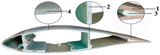
Figure 1.
DWTBs and four kinds of material position marking. 1—core material 1; 2—core material 2; 3—adhesive; 4—GFRC.

Table 1.
The quality ratio of four materials for DWTBs.
Table 2 shows the proximate analysis and ultimate analysis of GFRC, revealing the ash content is as high as 76.4%, and the ash is mainly glass fiber with a high melting point, which makes it difficult to degrade. Table 3 shows the XRF analysis of GFRC, in which the main elements are Si, Ca, Al, etc., with low levels of C and H elements contributing to its diminished calorific value.
Table 2.
Proximate analysis and ultimate analysis of GFRC.
Table 3.
XRF analysis of GFRC.
2.2. Experimental Study of Thermogravimetric Properties
The weight-loss characteristics of the four samples were analyzed by thermogravimetric analyzer under nitrogen atmosphere at a gas flow rate of 100 mL/min, and the temperature was 20–820 °C. TG and DTG curves were obtained through data processing. According to the conversion rate of the material, the relationship curve between and 1000/T was obtained by the Friedman method, and then the activation energy of the material was calculated according to the slope of the curve.
2.3. Experimental Study of Pyrolysis Properties
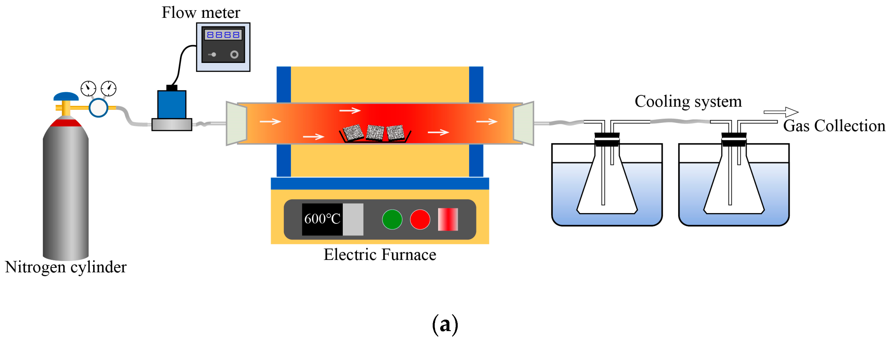
The pyrolysis experiments of the material were divided into fast pyrolysis experiment and slow pyrolysis experiment, and the effects of heating rate and experimental temperature, respectively, on the pyrolysis process were investigated. The slow pyrolysis experimental system, illustrated in Figure 2a, consisted of a nitrogen cylinder, mass flowm eter, horizontal tube furnace, condensing device, gas sampling device, and Fourier Transform Infrared Spectrometer. In each experiment, 40 g of the sample was put into the middle position of the quartz tube in the horizontal tube furnace, nitrogen was introduced into the quartz tube as the pyrolysis medium, and the flow rate of the gas was controlled by the mass flow meter to be 1 L/min. In the experiment, the temperature was set to increase from 20 °C to 900 °C at the rates of 15 °C/min, 20 °C/min, 25 °C/min, and 30 °C/min, respectively, according to the research of Ge et al. [37]. The composition of the pyrolysis gas was analyzed by Fourier Transform Infrared Spectrometer to determine the type and concentration of compounds in the gas mixture. Following the heating procedure of the tube furnace, the pyrolysis oil in the condensing unit was collected. After the tube furnace cooled to room temperature, the experimental sample was taken out of the quartz tube.

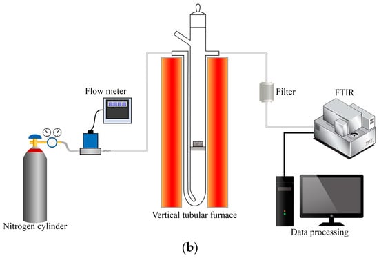
Figure 2.
Diagram of experimental device. (a). Slow pyrolysis system; (b). Fast pyrolysis system.
The fast pyrolysis system, depicted in Figure 2b, consists of a nitrogen gas cylinder, mass flow meter, vertical tube furnace, gas sampling device, and Fourier Transform Infrared Spectrometer. During the experiment, the set temperature was increased from 20 °C to 400 °C, 500 °C, 600 °C, and 700 °C, respectively, according to the research of Xu et al. [38]. The sample was placed at the inlet of the quartz tube, and the whole gas path was purged with nitrogen for about 30 s to ensure the inert atmosphere required for the pyrolysis reaction. A Fourier Transform Infrared Spectrometer was used to acquire the background gas of the system. After purging, the nitrogen flow rate was increased to blow the experimental samples into the reaction zone of the tube furnace, and the flow rate of nitrogen used in the experiment was about 2.7 L/min, with a sample mass of 1 g for each group. The composition and concentration of pyrolysis gas were analyzed by Fourier Transform Infrared Spectrometer.
2.4. Char Removal Experiment
The surface of the solid product after pyrolysis was covered with black carbide, requiring elimination to obtain pure glass fiber for subsequent reuse, which was also in line with the principle of sustainability [39]. The char removal experimental platform used the slow pyrolysis experimental platform as shown in Figure 2a, with the difference that the atmosphere was changed to air, so that the char underwent oxidation at higher temperatures. The generated gas was taken away to obtain high-value-added glass fiber.
3. Results and Discussion
3.1. Experimental Results of Thermogravimetric Properties
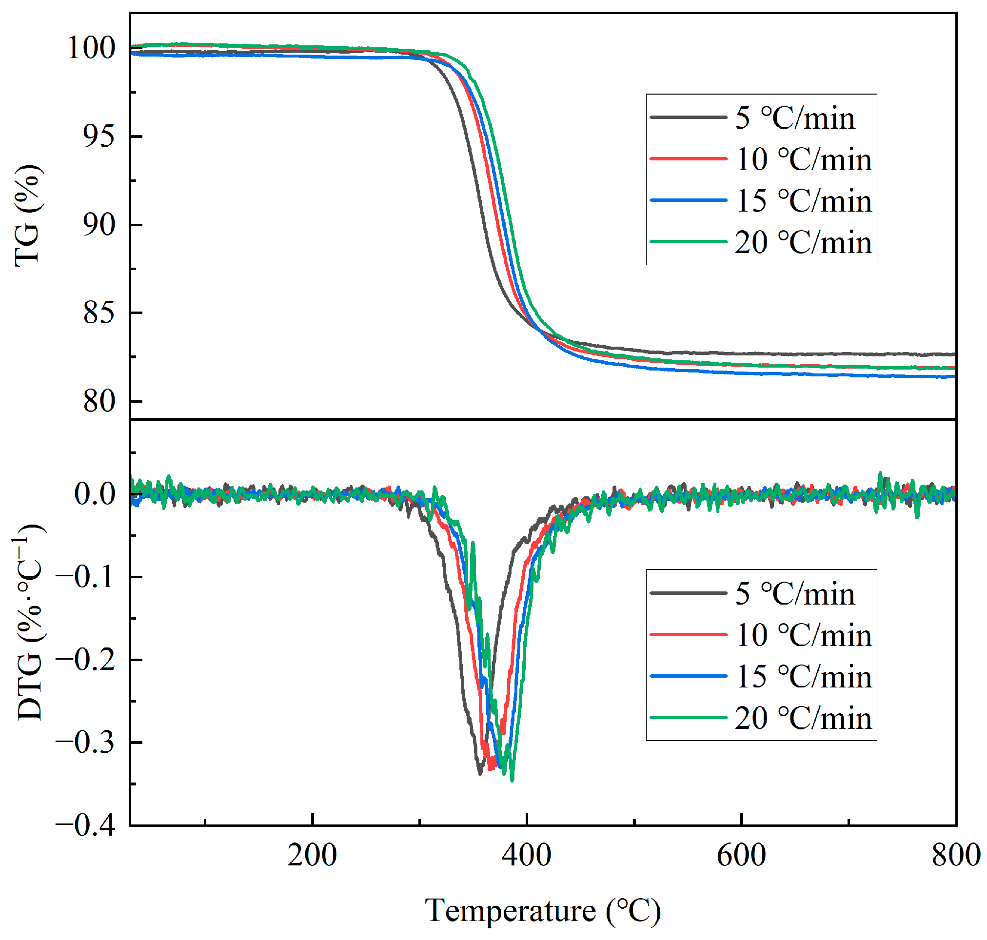
The TG and DTG curves of GFRC under different heating rates are shown in Figure 3, from which it can be seen that, at the lowest heating rate (5 °C/min), the mass of GFRC decreased starting at about 260 °C and remained basically unchanged at 522 °C. At this time, the pyrolysis reaction was completed and the weight loss was about 17.5%. At the highest heating rate (20 °C/min), the pyrolysis reaction of GFRC started at about 278 °C, and concluded at 530 °C, with a weight loss of about 18%. The corresponding DTG peaks at different heating rates were 356 °C, 363 °C, 380 °C, and 385 °C, respectively. The TG and DTG curves had the same change pattern, and all DTG curves had one peak, indicating that the pyrolysis of GFRC only had one rapid weight-loss process. With the increase in heating rate, the TG and DTG curves moved towards a higher temperature due to the limitation of heat transfer in the thermogravimetric experiments. At a higher heating rate of 20 °C/min, the surface temperature of the material rose rapidly, while the interior lagged behind, resulting in heating delay. Through the thermogravimetric analysis data, it can be seen that the pyrolysis reaction of DWTBs could be completed within the range of 600 °C.
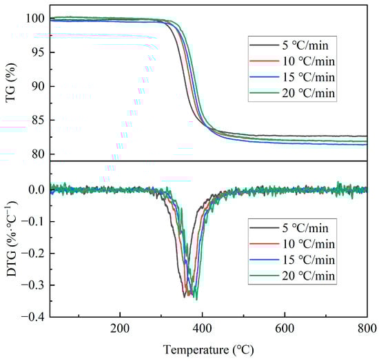
Figure 3.
TG/DTG curves of GFRC at different heating rates.
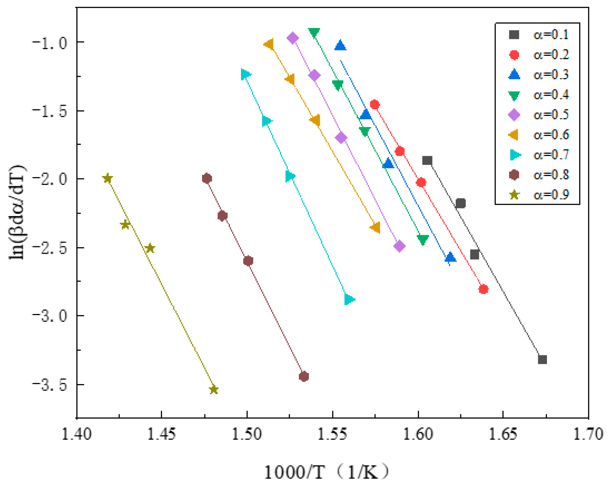
The activation energy refers to the energy barrier of the pyrolysis reaction, that is, the minimum energy required for the pyrolysis reaction to occur. The activation energy of the sample was calculated by the Friedman method. The relationship curves of and 1000/T under different conversion rates during DWTB pyrolysis were fitted, as shown in Figure 4. As can be seen from the figure, when α ranged from 0.1 to 0.9, the curves of and 1000/T had a good fit, and the activation energy of GFRC could be obtained according to the slope analysis of the curve, and its value was 196.0874 kJ/mol.
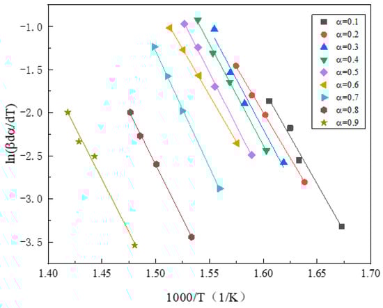
Figure 4.
The relationship curve between and 1000/T at various conversion rates fitted by Friedman method.
3.2. Experimental Results of Slow Pyrolysis Properties
3.2.1. Effect of Pyrolysis Time on Morphological Characteristics of Blades
Under the pyrolysis temperature of 550 °C, the pyrolysis time was set as 5 min, 10 min, 15 min, and 20 min, respectively, and the samples were taken out and scanned by SEM. The morphology changes during the pyrolysis of GFRC are illustrated in Figure 5a. Initially, the surface of the material turned brown gradually in about 5 min after the beginning of the pyrolysis, the reason being that the organic resin in the composite began to decompose to produce simple hydrocarbons at high temperatures, like methane, ethane, etc. These hydrocarbons reacted with carbon sources in the surrounding environment to form oxygen-containing or nitrogen-containing intermediary products, thereby causing a yellow or brown appearance on the surface [40,41]. About 15 min after the start of pyrolysis, it was observed that the brown color on the surface of the material changed to black. This was due to the further reaction of the above intermediates, the cracking of organic molecules, and the release of carbon elements, leading to the formation of carbonaceous substances, which accumulated on the surface of the material and caused it to turn black [42].
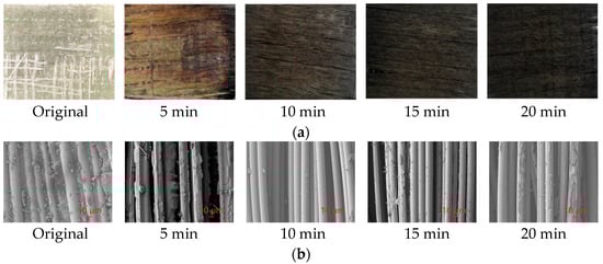
Figure 5.
Surface changes and SEM analysis during slow pyrolysis of GFRC. (a). Morphology changes at different pyrolysis time; (b). SEM analysis at different pyrolysis time.
The SEM analysis of GFRC with different reaction time is shown in Figure 5b. The original GFRC sample showed the glass fiber cylinder closely linked with the polymer. After the pyrolysis reaction at 550 °C for 5 min, the polymer on the surface of the glass fiber was partially decomposed. After 10 min of pyrolysis, the polymer was completely decomposed. Following 15 min of pyrolysis, carbides could be formed on the fiber surface. After pyrolysis for 20 min, a certain amount of carbide accumulated on the surface of the fiber.
3.2.2. Product Analysis of Slow Pyrolysis Process
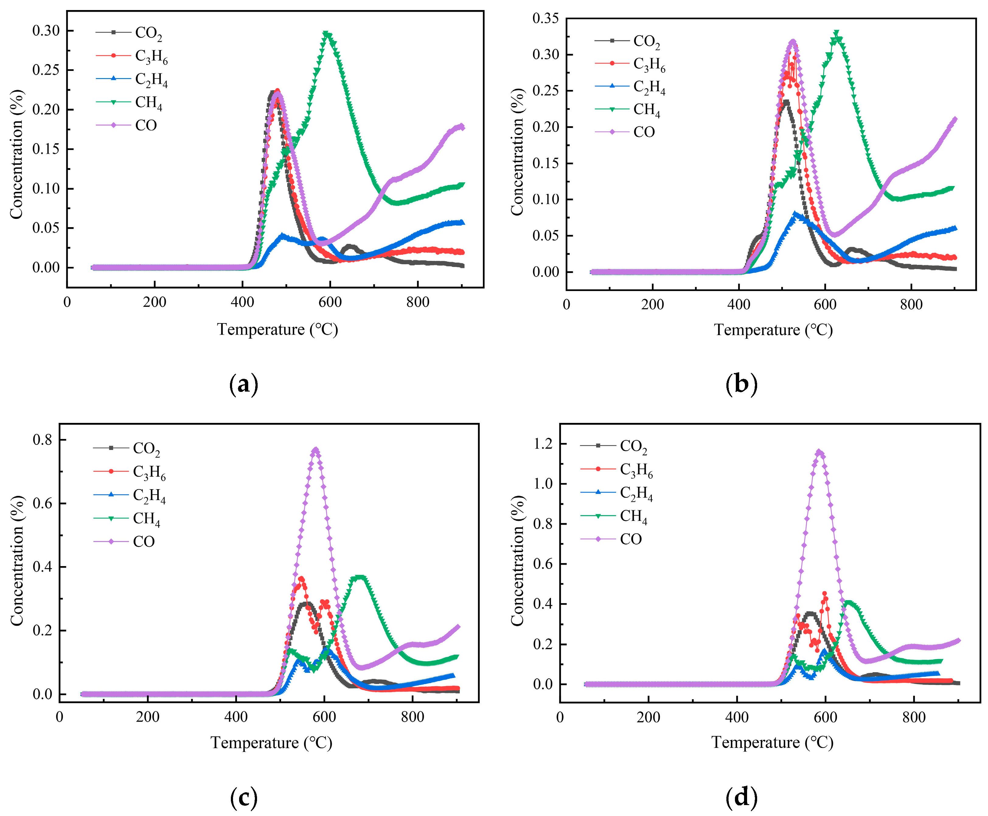
The generation characteristics of pyrolysis gas products at different heating rates are shown in Figure 6. At a heating rate of 15 °C/min, the amount of CH4 gas released was the largest, and its peak concentration was also the largest. When the heating rate was 20 °C/min, the peak concentrations of gases generated by pyrolysis were all increased, among which the peak concentration of CO increased to be close to that of CH4, and the peak concentrations of the two were the highest. When the temperature increase rate was 25 °C/min, the release of CO gas in the pyrolysis process increased significantly and surpassed other gases. The pyrolysis gas release pattern when the temperature increase rate was 30 °C/min was similar to that of 25 °C/min, and the release of CO gas was much larger than other gases.
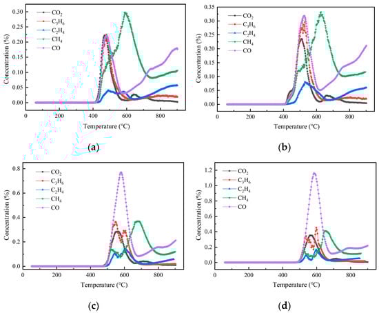
Figure 6.
Production characteristics of pyrolysis gas products at different heating rates. (a). 15 °C/min; (b). 20 °C/min; (c). 25 °C/min; (d). 30 °C/min.
In addition, pyrolysis gases at different heating rates were similar, including CO2, C3H6, C2H4, CH4, CO, etc., which differed only in the formation temperature and the peak concentration temperature. And the formation temperature and peak concentration temperature increased with the increase in heating rate, which was due to the thermal delay and uneven heat transfer caused by the increase in heating rate, which was consistent with the research results of Chen and Yun et al. [43,44]. The results showed that a higher heating rate could be selected for industrial pyrolysis of DWTBs to obtain a higher proportion of combustible gas, which was also beneficial to the recovery and utilization of GFRC pyrolysis gas.
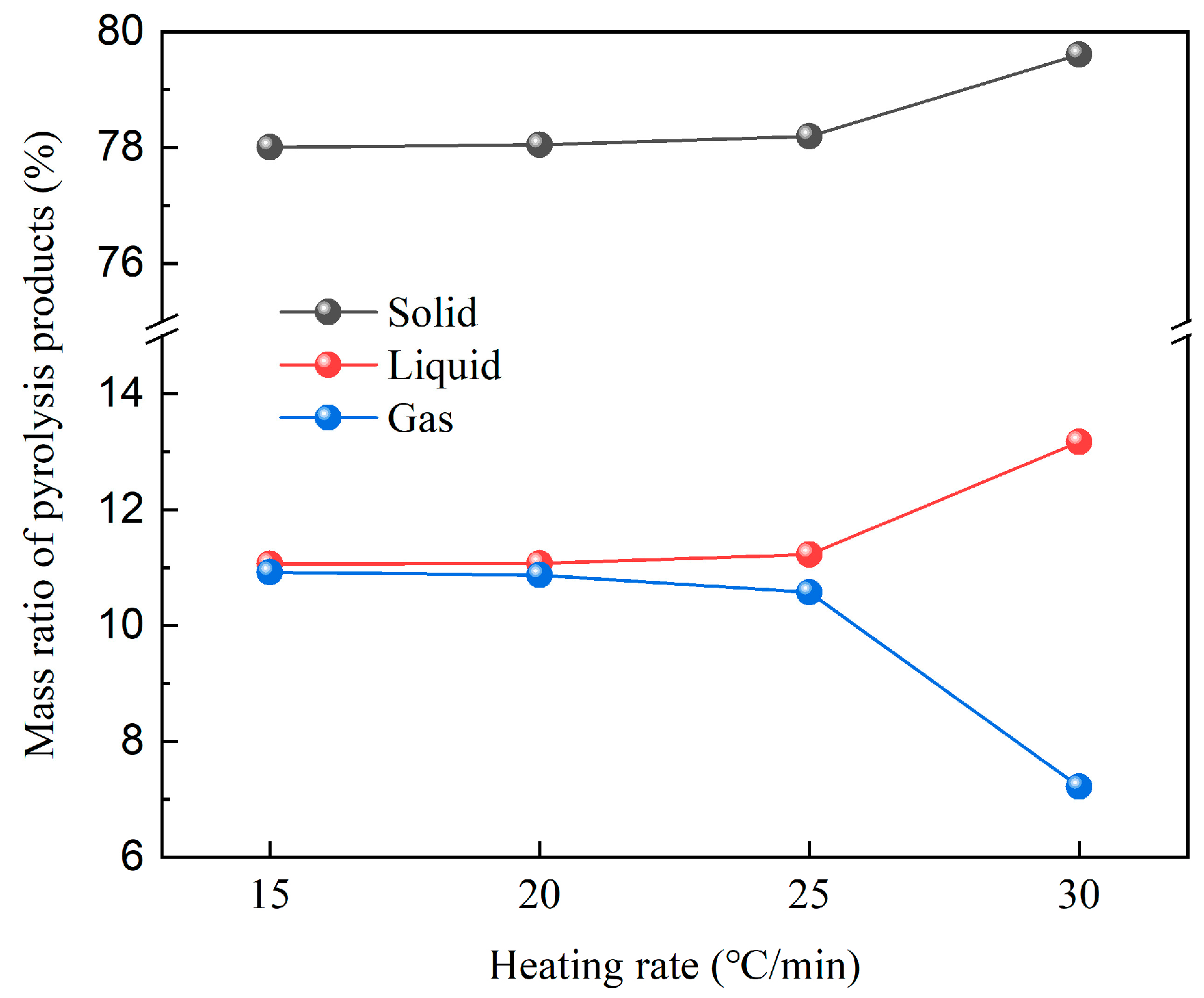
Figure 7 illustrates the mass percentage of the remaining solid, generated liquid, and generated gas after pyrolysis of GFRC at different heating rates. With the increase in heating rate, tar yield increased, gas and char yield decreased, but the overall difference was not significant; the tar yield obtained at the heating rate of 30 °C/min was 1.2 times higher than that of 15 °C/min. This can be attributed to the fact that the resin material reached the set temperature quickly at higher heating rates and then produced volatile free radical fragments, shortening the residence time of its escape from the inside of the material and reducing its reaction behavior.
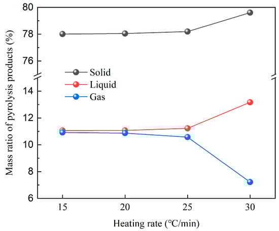
Figure 7.
Mass ratio of pyrolysis products under slow heating rate.
3.3. Experimental Results of Fast Pyrolysis Properties
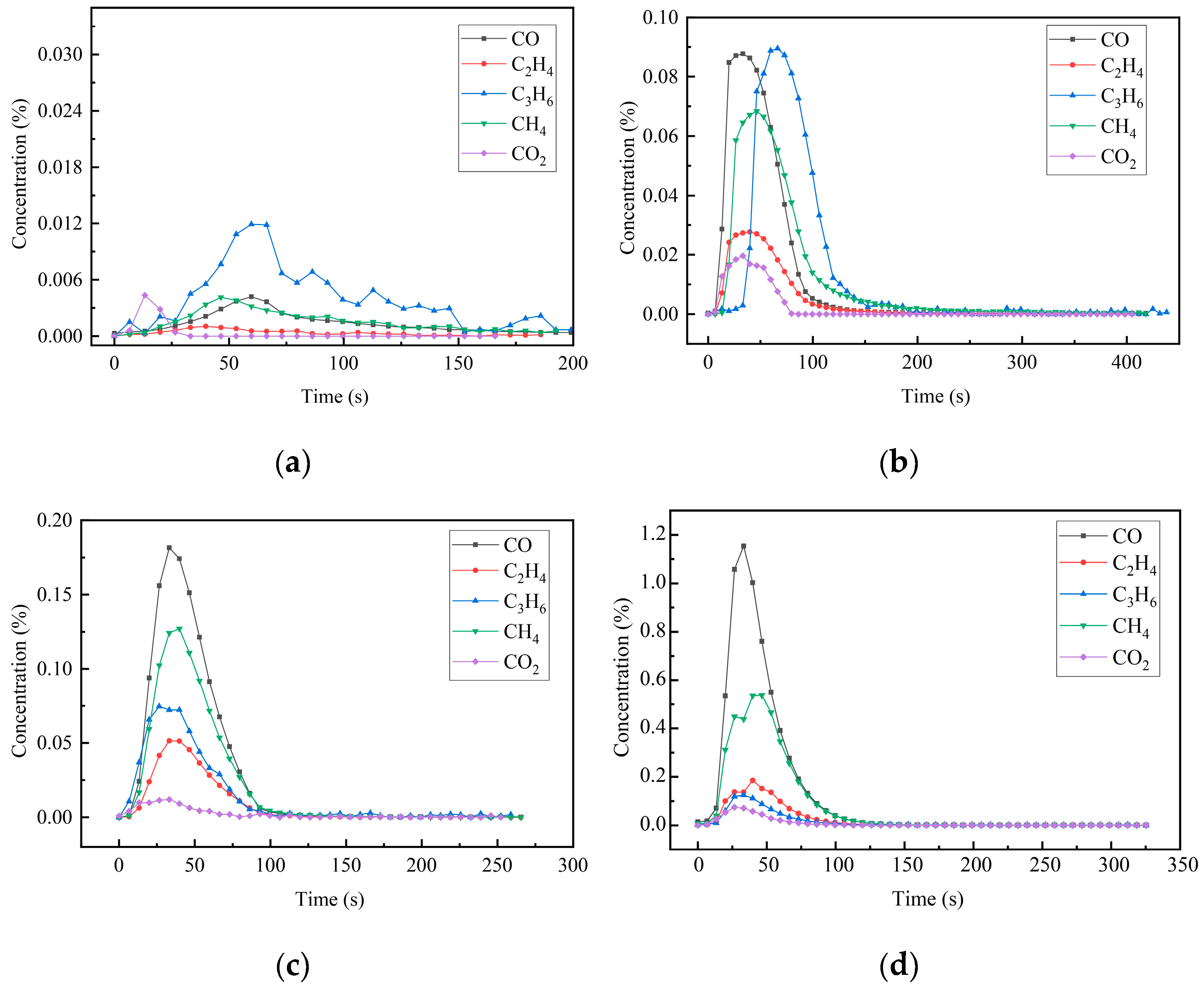
The emission patterns of CO, CH4, CO2, C2H4, and C3H6 gas concentrations over time under different temperature conditions are shown in Figure 8. At 400 °C, a small amount of gas was released during the pyrolysis process. The concentration of C3H6 gas was relatively high, and the release of CO2 gas was the earliest. When the temperature was 500 °C, the concentration of CO, C3H6, and CH4 gas increased significantly. Among these, CO and C3H6 exhibited the highest concentrations, and their peak concentrations were close, followed by CH4. When the temperature was 600 °C, CO emission was the most prominent, and the release of CO2 was the least. When the pyrolysis temperature was 700 °C, the release amount of CO gas was the largest, there was a significant gap between the release of other gases, and the release amount of CO2 was the least. However, at a higher pyrolysis temperature, the performance of glass fiber would be seriously damaged. For comprehensive consideration, it is recommended that the industrial pyrolysis temperature should be 600 °C to realize the high calorific value of pyrolysis gas and the maximum retention of glass fiber strength.
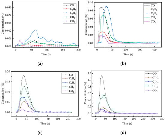
Figure 8.
Production characteristics of pyrolysis gas products at different pyrolysis temperatures. (a). 400 °C; (b). 500 °C; (c). 600 °C; (d). 700 °C.
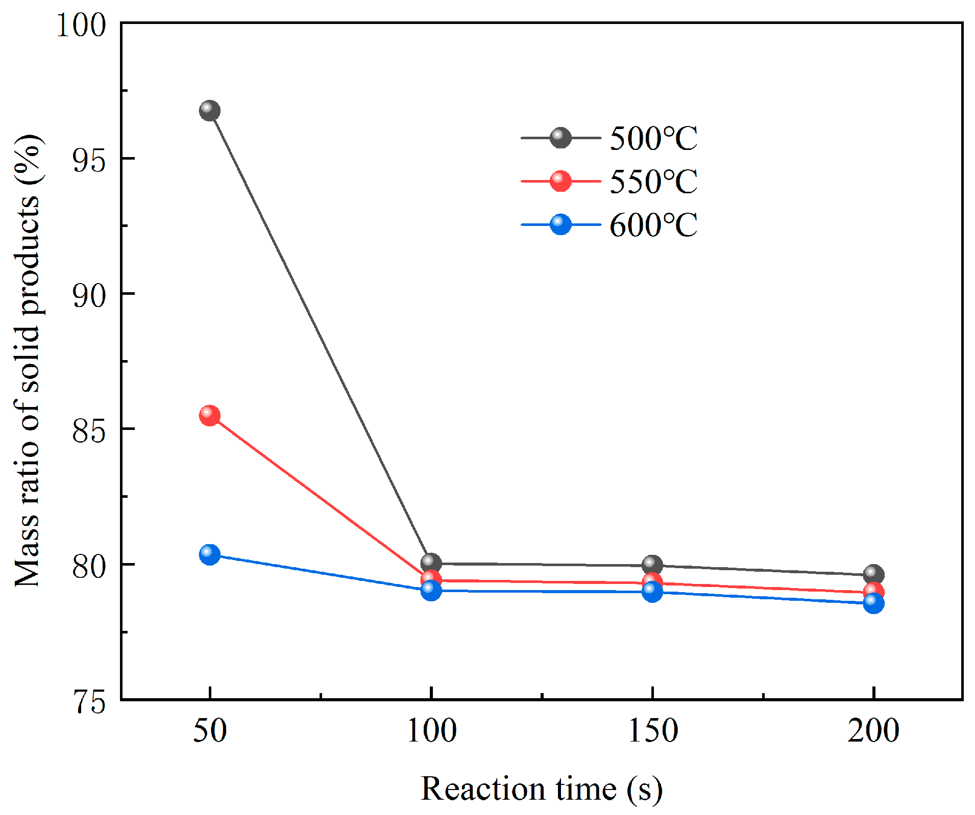
Figure 9 shows the variations of residual solid mass at different pyrolysis temperatures. The data illustrate a decrease in both the rate of weight loss and the amount of weight lost from GFRC materials as the pyrolysis temperature increases. High temperature intensified the formation and reaction of volatiles, resulting in more complete pyrolysis and higher volatile components. In addition, by comparing the yield and concentration of pyrolysis gas at 400 °C and 600 °C, complete pyrolysis could be achieved faster at temperatures of 600 °C, and the gas generated by pyrolysis at 600 °C contained a higher amount of CH4 and CO, which was because the decomposition of GFRC material was more sufficient and more methyl radicals were generated to form more CH4. The temperature increment was also conducive to the secondary pyrolysis of pyrolysis oil to generate combustible gas. Overall, pyrolysis at 600 °C will produce more combustible gas, which has higher economic and recycling value and can be used as combustible gas.
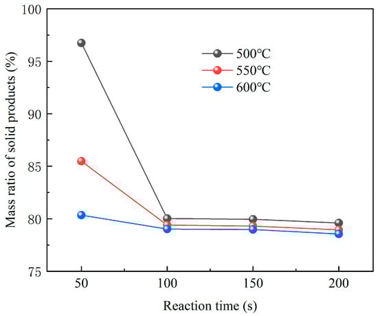
Figure 9.
Mass ratio of residual solids at different pyrolysis temperatures.
3.4. Experimental Results of Char Removal Experiment
The solid product obtained by pyrolysis at 600 °C for 10 min was taken as the research object. The char removal reaction temperature was set at 550 °C in an air atmosphere, and the residence time was 10 min, 20 min, 30 min, 40 min, 50 min, and 60 min, respectively. The removal process of carbide on the surface of glass fiber is shown in Figure 10. It can be seen that when the oxidation time was about 40 min, the carbide on the surface of glass fiber reacted completely. At this time, the surface of the fiber was white, and glass fiber with a relatively clean surface was obtained.
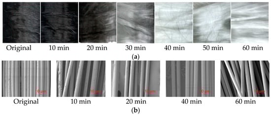
Figure 10.
Removal of char from glass fiber surface and SEM analysis. (a). Sample after pyrolysis at different time; (b). SEM analysis at different time.
4. Simulation of Pyrolysis Process
Most current pyrolysis experiments require external heating and a separate supply of pyrolysis atmosphere [45,46,47,48], leading to high energy consumption and costs. In order to reduce the cost of centralized treatment of DWTBs, this study innovatively proposed a thermal energy utilization scheme in which pyrolysis gas was re-combusted as fuel and the flue gas after combustion was used as the pyrolysis medium, and its performance was predicted. The feasibility of CO2 atmosphere as a pyrolysis atmosphere has been demonstrated [49].
4.1. Pyrolysis System Model
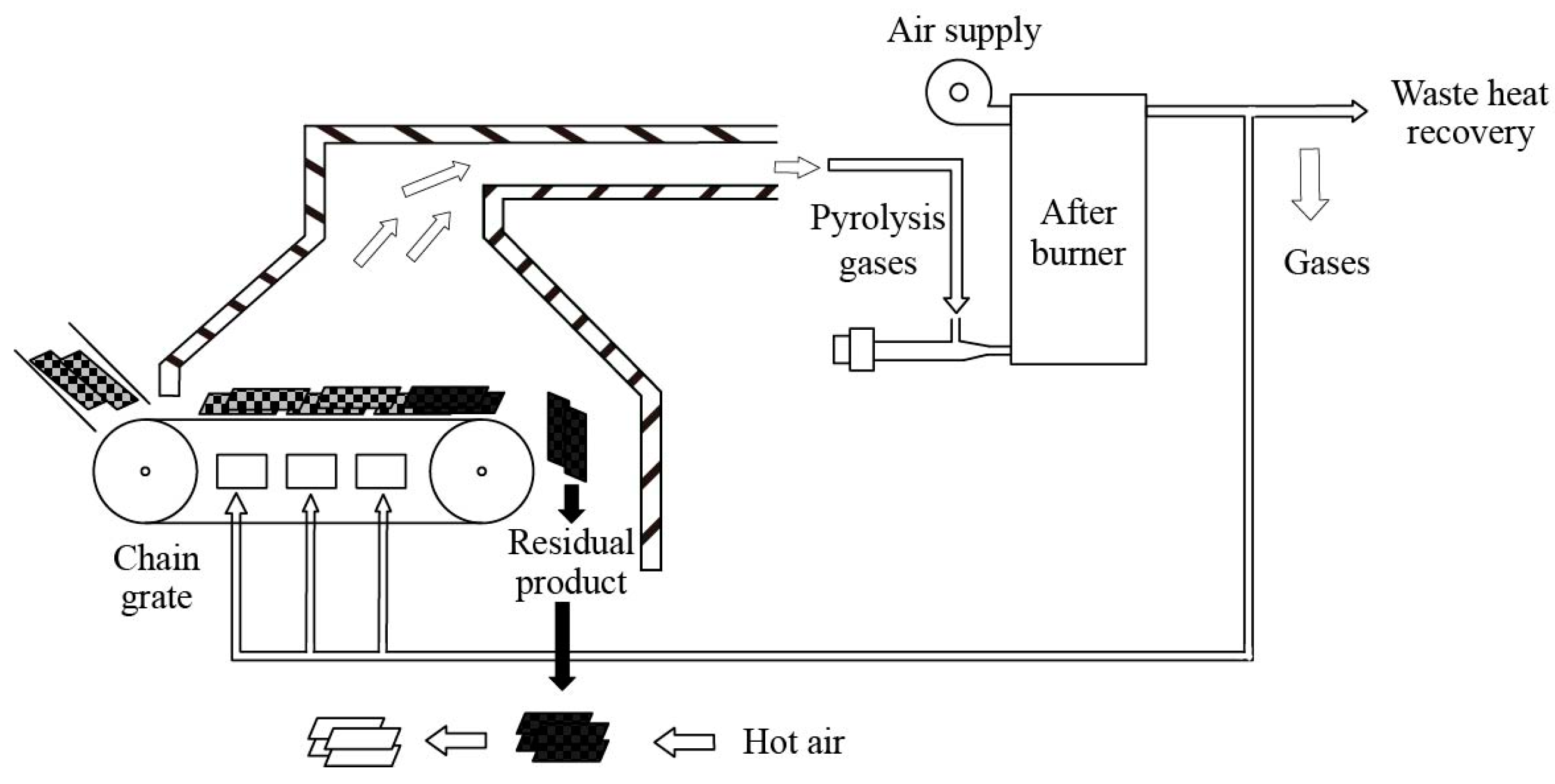
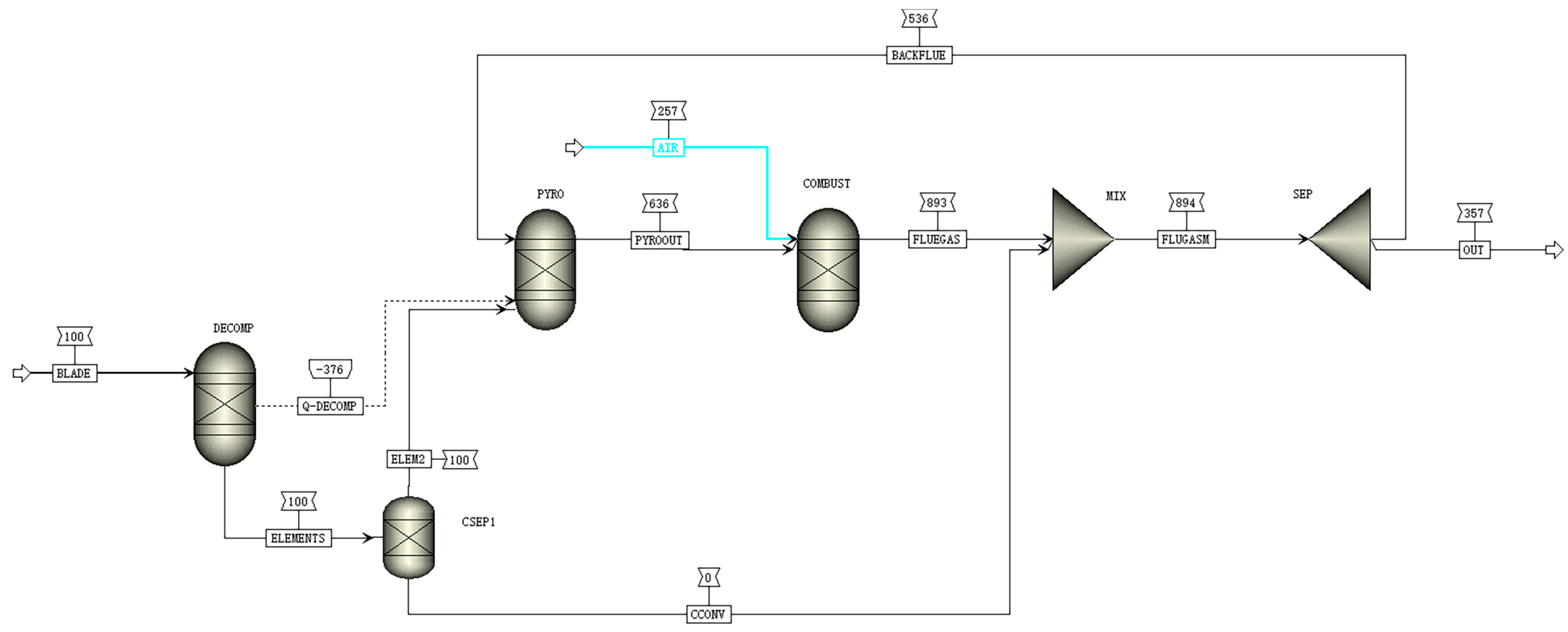
The DWTB pyrolysis system is based on the following pyrolysis treatment process, which is illustrated in Figure 11, which consists of a feeding system, chain furnace pyrolysis system, and re-combustion system. The DWTBs were pre-cut before the pyrolysis reaction, with the feeding system transporting the material to the chain grate furnace. The feeding system could adjust the amount and speed of the materials according to the actual needs to ensure the stability and continuity of the pyrolysis reaction. The blade underwent high-temperature pyrolysis reaction in the chain grate furnace, the heat was provided by hot fuel gas, the pyrolysis gas was introduced into the re-burner for combustion, and the non-reactive glass fiber was collected for subsequent treatment and reuse. The use of a chain grate greatly satisfied the need for continuous treatment and stable pyrolysis of DWTBs, and preserved the integrity of the fibers. According to the basic flow of the proposed pyrolysis process, a process flow diagram as shown in Figure 12 was established based on Aspen Plus software.
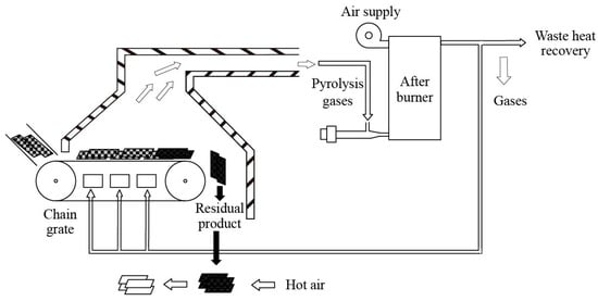
Figure 11.
Flow chart of pyrolysis treatment process of DWTBs.
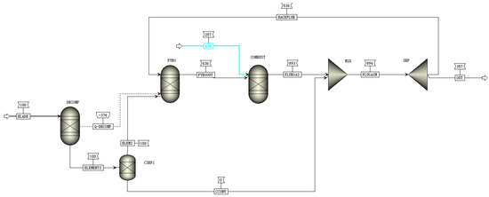
Figure 12.
Process flow of wind turbine blade pyrolysis system based on Aspen Plus.
The pyrolysis reactions of DWTBs involve pyrolysis reactions and combustion reactions, which are respectively realized by the pyrolysis module and the combustion module in the system. The reactions in both the pyrolysis module and the combustion module are achieved by the RGibbs reactor, which is a thermodynamically balanced reactor based on the Gibbs free energy minimization principle [50,51,52]. The boundary conditions of the pyrolysis system process flow model are shown in Table 4.
Table 4.
Boundary conditions of the pyrolysis system model.
The pyrolysis reaction is mainly the pyrolysis reaction of polymer organic matter in DWTBs, and the products are mainly C, H2, H2O, CO, CO2, CH4, tar, and other hydrocarbon substances, which can be approximated by chemical equation:
4.2. Simulation Results and Analysis
When the pyrolysis temperature was 550 °C, the mass flow rate of each section of the DWTB pyrolysis system was calculated. The pyrolysis gas had a low calorific value of 1503 kJ/kg, with gases containing high calorific values being H2, CO, and CH4.
By adjusting the proportion of the recirculation flue gas (defined as the proportion of flue gas used as the pyrolysis medium), simulation yielded operational data under various conditions. The pyrolysis temperature and flue gas temperature under different recirculation ratios are shown in Figure 13. The pyrolysis temperature was modifiable by adjusting the recirculation flue gas ratio. The pyrolysis temperature increased from 267 °C to 867 °C when the recirculation flue gas ratio increased from 0.4 to 0.8. With the increase in the proportion of recirculation flue gas, the flue gas temperature after pyrolysis gas combustion had almost no change. At a 66% recirculation flue gas ratio, the pyrolysis temperature was 600 °C, meeting the temperature required for the pyrolysis of DWTBs.
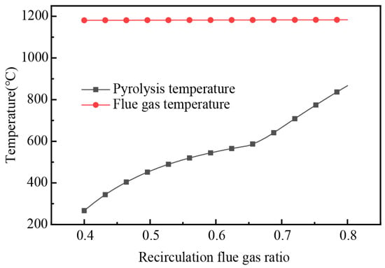
Figure 13.
The variation of pyrolysis temperature and flue gas temperature with the change in recirculation flue gas ratio.
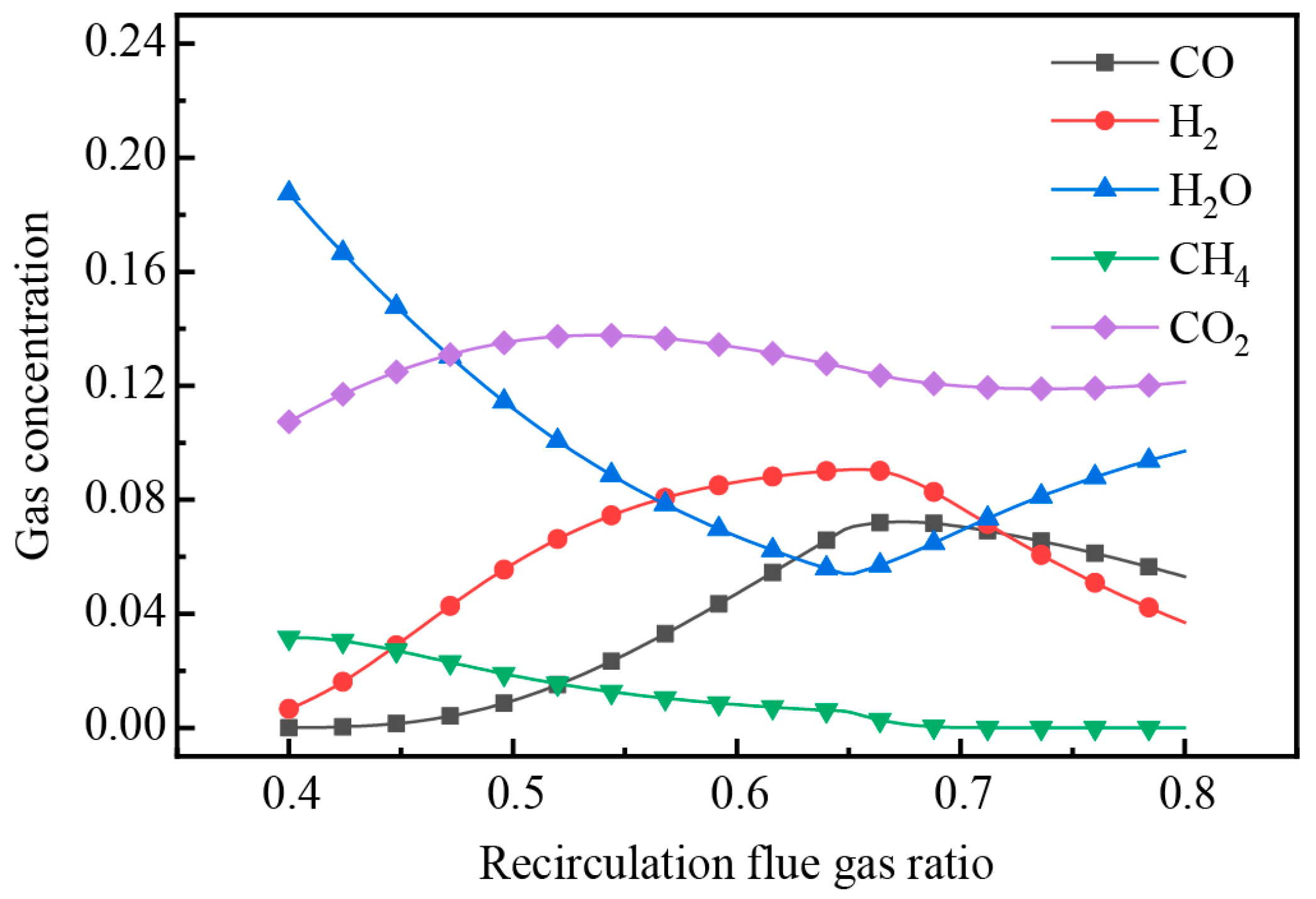
Setting the pyrolysis temperature at 600 °C and altering the proportion of recirculation flue gas, the changes of pyrolysis gas composition are depicted in Figure 14. The trends indicated that the gas concentration of CO2, H2, and CO initially increased and then decreased as the ratio of recirculation flue gas increased, while H2O was the opposite, which was mainly affected by the dilution effect of the flue gas on the pyrolysis gas. CH4 showed a decreasing trend, because its generation was inhibited in the CO2 atmosphere. The H2 and CH4 concentration in the pyrolysis gas almost reached the highest value when the recirculation flue gas ratio was 66%, and the pyrolysis gas also had a high calorific value, indicating that it was the optimal ratio for the pyrolysis treatment of DWTBs in this process.
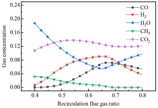
Figure 14.
The variation of pyrolysis gas concentration with the change in recirculation flue gas ratio.
When conducting industrial scale-up experiments based on simulation results, additional attention should be paid to the insulation of the pipeline to prevent the blockage and corrosion of the pipeline due to tar condensation. At the same time, an appropriate heating rate can be adopted to achieve higher pyrolysis gas production and energy recovery efficiency. In the process of char removal, adequate oxygen supply is maintained to avoid the production of toxic gases such as CO, and heat exchangers can be installed to achieve higher energy recovery efficiency.
According to the pyrolysis experiment, the key parameters of pyrolysis were obtained. The feasibility of the pyrolysis-energy recovery scheme was verified by numerical simulation, and the appropriate intermediate parameters were calculated. At the same time as the final realization of solid waste reduction, the energy self-maintenance of the whole heat treatment process was realized, making it a profitable treatment method, which also provided a reference for other types of solid waste treatment.
5. Conclusions
Aiming at the development of low-energy-consumption treatment and resource utilization technology, this paper studied the thermogravimetric, slow pyrolysis and fast pyrolysis characteristics of wind turbine blade pyrolysis by means of experimental research and numerical simulation. A low-cost, low-energy-consumption and low-pollution pyrolysis process for DWTBs (decommissioned wind turbine blades) is innovatively proposed. Aspen Plus was employed to carry out the process simulation calculation, which verified the feasibility of the scheme and proposed appropriate process operation parameters.
The weight-loss law and kinetic properties of the pyrolysis process of GFRC, the main component of wind turbine blade materials, were analyzed. By studying the weightlessness-temperature law of GFRC, it was found that the pyrolysis reaction of DWTBs could be basically completed at around 600 °C, to provide data reference for the development of a pyrolysis experiment.
A slow pyrolysis experimental system was established to investigate the pyrolysis characteristics of GFRC at different heating rates. The formation temperature, peak concentration, and corresponding temperature of CO2, C3H6, C2H4, CH4, and CO produced by GFRC pyrolysis, along with the proportion of combustible gas in pyrolysis gases, all rose with the increase in heating rate. After the pyrolysis of GFRC at 600 °C, the solid product can be oxidized at 550 °C for 40 min to obtain clean glass fiber. It provided a new way to solve the current situation of the high cost and low benefit of DWTB pyrolysis.
A fast pyrolysis experimental system was established to analyze the pyrolysis characteristics of GFRC at different temperatures. When the pyrolysis temperature was 400–900 °C, the peak concentration of CO gas produced by GFRC pyrolysis was the highest, the peak concentration of CO, CH4, and C2H4 was at 700 °C and 900 °C, and the peak concentration of CO2 and C3H6 was at 700 °C. During the pyrolysis of GFRC materials, the yield of solid products decreased with the increase in temperature and the extension of reaction time. The fast pyrolysis experiment was closer to the parameters of an industrial-scale pyrolysis device, which could provide a reference for industrial-scale DWTB pyrolysis.
The thermal energy utilization scheme of pyrolysis gas re-combustion as the pyrolysis medium of DWTBs was proposed, and a numerical simulation was carried out by Aspen Plus to predict the performance of the process: the pyrolysis temperature increased with the increase in the proportion of recirculation flue gas. The pyrolysis temperature could reach 600 °C when the proportion of recirculation flue gas was 66%, which met the temperature required for the pyrolysis of DWTBs. It provides a reference for the pyrolysis device to achieve low energy consumption, miniaturization, and compactness.
Author Contributions
Conceptualization and data curation, D.Z.; funding acquisition, Z.H.; investigation and writing—original draft, X.S. (Xiaobei Shi) and X.S. (Xiaofei Sun); methodology, T.Z.; project administration, H.Y.; writing—review and editing, R.B. and M.Z. All authors have read and agreed to the published version of the manuscript.
Funding
This work was supported by the Beijing Natural Science Foundation “Research on circulating fluidized bed combustion reconstruction method and resource utilization of high-aluminum coal ash” (JQ23010).
Data Availability Statement
Data are contained within the article.
Conflicts of Interest
The authors declare no conflicts of interest. The funders had no role in the design of the study; in the collection, analyses, or interpretation of data; in the writing of the manuscript; or in the decision to publish the results.
References
- Saidur, R.; Islam, M.R.; Rahim, N.A.; Solangi, K.H. A review on global wind energy policy. Renew. Sustain. Energy Rev. 2010, 14, 1744–1762. [Google Scholar] [CrossRef]
- Timilsina, G.R.; van Kooten, G.C.; Narbel, P.A. Global wind power development: Economics and policies. Energy Policy 2013, 61, 642–652. [Google Scholar] [CrossRef]
- Zhang, S.; Wei, J.; Chen, X.; Zhao, Y. China in global wind power development: Role, status and impact. Renew. Sustain. Energy Rev. 2020, 127, 109881. [Google Scholar] [CrossRef]
- Psomopoulos, C.S.; Kalkanis, K.; Kaminaris, S.; Ioannidis, G.C.; Pachos, P. A review of the potential for the recovery of wind turbine blade waste materials. Recycling 2019, 4, 7. [Google Scholar] [CrossRef]
- Eder, M.A.; Belloni, F.; Tesauro, A.; Hanis, T. A multi-frequency fatigue testing method for wind turbine rotor blades. J. Sound Vib. 2017, 388, 123–140. [Google Scholar] [CrossRef]
- Wu, Y.; Ge, Z.; Huang, C.; Zha, Z.; Zeng, M.; Ma, Y.; Sun, L.; Hou, Z.; Chu, S.; Zhang, H. In-situ pyrolysis kinetic analysis and fixed-bed pyrolysis behavior of ex-service wind turbine blades. Waste Manag. 2023, 168, 54–62. [Google Scholar] [CrossRef]
- Ortegon, K.; Nies, L.F.; Sutherland, J.W. Preparing for end of service life of wind turbines. J. Clean. Prod. 2013, 39, 191–199. [Google Scholar] [CrossRef]
- Liu, P.; Barlow, C.Y. Wind turbine blade waste in 2050. Waste Manag. 2017, 62, 229–240. [Google Scholar] [CrossRef]
- Lichtenegger, G.; Rentizelas, A.A.; Trivyza, N.; Siegl, S. Offshore and onshore wind turbine blade waste material forecast at a regional level in Europe until 2050. Waste Manag. 2020, 106, 120–131. [Google Scholar] [CrossRef]
- Beauson, J.; Laurent, A.; Rudolph, D.; Jensen, J.P. The complex end-of-life of wind turbine blades: A review of the European context. Renew. Sustain. Energy Rev. 2022, 155, 111847. [Google Scholar] [CrossRef]
- Xiong, X.; Li, L.; Chen, F.; Zhang, J.; Tan, H. Typical pollutant species evolution behaviors study in retired wind turbine blade and coal thermal conversion process. J. Anal. Appl. Pyrolysis 2022, 168, 105771. [Google Scholar] [CrossRef]
- Ge, L.; Xu, C.; Feng, H.; Jiang, H.; Li, X.; Lu, Y.; Sun, Z.; Wang, Y.; Xu, C. Study on isothermal pyrolysis and product characteristics of basic components of waste wind turbine blades. J. Anal. Appl. Pyrolysis 2023, 171, 105964. [Google Scholar] [CrossRef]
- Mishnaevsky, L., Jr.; Branner, K.; Petersen, H.N.; Beauson, J.; McGugan, M.; Sørensen, B.F. Materials for wind turbine blades: An overview. Materials 2017, 10, 1285. [Google Scholar] [CrossRef]
- Brøndsted, P.; Lilholt, H.; Lystrup, A. Composite materials for wind power turbine blades. Annu. Rev. Mater. Res. 2005, 35, 505–538. [Google Scholar] [CrossRef]
- Sommer, V.; Walther, G. Recycling and recovery infrastructures for glass and carbon fiber reinforced plastic waste from wind energy industry: A European case study. Waste Manag. 2021, 121, 265–275. [Google Scholar] [CrossRef]
- Utekar, S.; Suriya, V.K.; More, N.; Rao, A. Comprehensive study of recycling of thermosetting polymer composites—Driving force, challenges and methods. Compos. Part B-Eng. 2021, 207, 108596. [Google Scholar] [CrossRef]
- Du, C.; Jin, G.; Zhang, L.; Tong, B.; Wang, B.; Zhang, G.; Cheng, Y. Zero–Waste Recycling of Fiber/Epoxy from Scrap Wind Turbine Blades for Effective Resource Utilization. Polymers 2022, 14, 5408. [Google Scholar] [CrossRef]
- Jensen, J.P.; Skelton, K. Wind turbine blade recycling: Experiences, challenges and possibilities in a circular economy. Renew. Sustain. Energy Rev. 2018, 97, 165–176. [Google Scholar] [CrossRef]
- Cherrington, R.; Goodship, V.; Meredith, J.; Wood, B.M.; Coles, S.R.; Vuillaume, A.; Feito-Boirac, A.; Spee, F.; Kirwan, K. Producer responsibility: Defining the incentive for recycling composite wind turbine blades in Europe. Energy Policy 2012, 47, 13–21. [Google Scholar] [CrossRef]
- Larsen, K. Recycling wind. Reinf. Plast. 2009, 53, 20–25. [Google Scholar] [CrossRef]
- Grause, G.; Mochizuki, T.; Kameda, T.; Yoshioka, T. Recovery of glass fibers from glass fiber reinforced plastics by pyrolysis. J. Mater. Cycles Waste Manag. 2013, 15, 122–128. [Google Scholar] [CrossRef]
- Guo, J.; Tang, Y.; Xu, Z. Wood Plastic Composite Produced by Nonmetals from Pulverized Waste Printed Circuit Boards. Environ. Sci. Technol. 2010, 44, 463–468. [Google Scholar] [CrossRef]
- Mishnaevsky, L., Jr. Sustainable end-of-life management of wind turbine blades: Overview of current and coming solutions. Materials 2021, 14, 1124. [Google Scholar] [CrossRef]
- Liu, P.; Meng, F.; Barlow, C.Y. Wind turbine blade end-of-life options: An eco-audit comparison. J. Clean. Prod. 2019, 212, 1268–1281. [Google Scholar] [CrossRef]
- Rani, M.; Choudhary, P.; Krishnan, V.; Zafar, S. A review on recycling and reuse methods for carbon fiber/glass fiber composites waste from wind turbine blades. Compos. Part B Eng. 2021, 215, 108768. [Google Scholar] [CrossRef]
- Delvere, I.; Iltina, M.; Shanbayev, M.; Abildayeva, A.; Kuzhamberdieva, S.; Blumberga, D. Evaluation of Polymer Matrix Composite Waste Recycling Methods. Environ. Clim. Technol. 2019, 23, 168–187. [Google Scholar] [CrossRef]
- Li, J.; Xu, P.-L.; Zhu, Y.-K.; Ding, J.-P.; Xue, L.-X.; Wang, Y.-Z. A promising strategy for chemical recycling of carbon fiber/thermoset composites: Self-accelerating decomposition in a mild oxidative system. Green Chem. 2012, 14, 3260–3263. [Google Scholar] [CrossRef]
- Chen, J.; Wang, J.; Ni, A. Recycling and reuse of composite materials for wind turbine blades: An overview. J. Reinf. Plast. Compos. 2019, 38, 567–577. [Google Scholar] [CrossRef]
- Ge, L.; Li, X.; Feng, H.; Xu, C.; Lu, Y.; Chen, B.; Li, D.; Xu, C. Analysis of the pyrolysis process, kinetics and products of the base components of waste wind turbine blades (epoxy resin and carbon fiber). J. Anal. Appl. Pyrolysis 2023, 170, 105919. [Google Scholar] [CrossRef]
- Khalid, M.Y.; Arif, Z.U.; Hossain, M.; Umer, R. Recycling of wind turbine blades through modern recycling technologies: A road to zero waste. Renew. Energy Focus 2023, 44, 373–389. [Google Scholar] [CrossRef]
- Yang, W.; Kim, K.-H.; Lee, J. Upcycling of decommissioned wind turbine blades through pyrolysis. J. Clean. Prod. 2022, 376, 134292. [Google Scholar] [CrossRef]
- Hu, J.; Danish, M.; Lou, Z.; Zhou, P.; Zhu, N.; Yuan, H.; Qian, P. Effectiveness of wind turbine blades waste combined with the sewage sludge for enriched carbon preparation through the co-pyrolysis processes. J. Clean. Prod. 2018, 174, 780–787. [Google Scholar] [CrossRef]
- Xu, M.; Ji, H.; Meng, X.; Yang, J.; Wu, Y.; Di, J.; Jiang, H.; Lu, Q. Effects of core materials on the evolution of products during the pyrolysis of end-of-life wind turbine blades. J. Anal. Appl. Pyrolysis 2023, 175, 106222. [Google Scholar] [CrossRef]
- Zhang, D.; Song, Q.; Hou, B.; Zhang, M.; Teng, D.; Zhang, Y.; Bie, R.; Yang, H. Experimental Study on Microwave Pyrolysis of Decommissioned Wind Turbine Blades Based on Silicon Carbide Absorbents. Processes 2024, 12, 1065. [Google Scholar] [CrossRef]
- Yousef, S.; Eimontas, J.; Striugas, N.; Abdelnaby, M.A. Recovery of styrene from waste wind turbine blades (fiberglass/polyester resin composites) using pyrolysis treatment and its kinetic behavior. J. Therm. Anal. Calorim. 2024, 149, 521–538. [Google Scholar] [CrossRef]
- Wu, Z.; Li, C.; Shan, R.; Zhang, J. Synergistic Effects for Co-pyrolysis of Epoxy Resin and Polyurethane from Retired Wind Turbine Blades. Waste Biomass Valorization 2024, 15, 1603–1614. [Google Scholar] [CrossRef]
- Ge, L.; Jiang, H.; Feng, H.; Xu, C.; Lu, Y.; Li, X.; Chen, B.; Xu, C. Study on the thermal transformation of basic components of wind turbine blade. Asia-Pac. J. Chem. Eng. 2023, 18, e2938. [Google Scholar] [CrossRef]
- Xu, M.; Meng, X.; Ji, H.; Yang, J.; Di, J.; Wu, Y.; Lu, Q. Evolution of pyrolysis char during the recovery of carbon fiber reinforced polymer composite and its effects on the recovered carbon fiber. J. Environ. Chem. Eng. 2024, 12, 112214. [Google Scholar] [CrossRef]
- Tsimnadis, K.; Kyriakopoulos, G.L.; Leontopoulos, S. Practical Improvement Scenarios for an Innovative Waste-Collection Recycling Program Operating with Mobile Green Points (MGPs). Inventions 2023, 8, 80. [Google Scholar] [CrossRef]
- Xiao, R.; Yang, W.; Cong, X.; Dong, K.; Xu, J.; Wang, D.; Yang, X. Thermogravimetric analysis and reaction kinetics of lignocellulosic biomass pyrolysis. Energy 2020, 201, 117537. [Google Scholar] [CrossRef]
- Chen, R.; Xu, X.; Lu, S.; Zhang, Y.; Lo, S. Pyrolysis study of waste phenolic fibre-reinforced plastic by thermogravimetry/Fourier transform infrared/mass spectrometry analysis. Energy Convers. Manag. 2018, 165, 555–566. [Google Scholar] [CrossRef]
- Mishra, R.K.; Mohanty, K.; Wang, X. Pyrolysis kinetic behavior and Py-GC–MS analysis of waste dahlia flowers into renewable fuel and value-added chemicals. Fuel 2020, 260, 116338. [Google Scholar] [CrossRef]
- Chen, W.; Ye, M.; Li, M.; Xi, B.; Hou, J.; Qi, X.; Zhang, J.; Wei, Y.; Meng, F. Characteristics, kinetics and product distribution on pyrolysis process for waste wind turbine blades. J. Anal. Appl. Pyrolysis 2023, 169, 105859. [Google Scholar] [CrossRef]
- Yun, Y.M.; Seo, M.W.; Koo, G.H.; Ra, H.W.; Yoon, S.J.; Kim, Y.K.; Lee, J.G.; Kim, J.H. Pyrolysis characteristics of GFRP (Glass Fiber Reinforced Plastic) under non-isothermal conditions. Fuel 2014, 137, 321–327. [Google Scholar] [CrossRef]
- Åkesson, D.; Foltynowicz, Z.; Christeen, J.; Skrifvars, M. Products obtained from decomposition of glass fibre-reinforced composites using microwave pyrolysis. Polimery 2013, 58, 582–586. [Google Scholar] [CrossRef]
- Anuar Sharuddin, S.D.; Abnisa, F.; Wan Daud, W.M.A.; Aroua, M.K. A review on pyrolysis of plastic wastes. Energy Convers. Manag. 2016, 115, 308–326. [Google Scholar] [CrossRef]
- Jouhara, H.; Nannou, T.K.; Anguilano, L.; Ghazal, H.; Spencer, N. Heat pipe based municipal waste treatment unit for home energy recovery. Energy 2017, 139, 1210–1230. [Google Scholar] [CrossRef]
- Huang, Y.-F.; Chiueh, P.-T.; Kuan, W.-H.; Lo, S.-L. Microwave pyrolysis of lignocellulosic biomass: Heating performance and reaction kinetics. Energy 2016, 100, 137–144. [Google Scholar] [CrossRef]
- Xu, M.; Ji, H.; Wu, Y.; Di, J.; Meng, X.; Jiang, H.; Lu, Q. The pyrolysis of end-of-life wind turbine blades under different atmospheres and their effects on the recovered glass fibers. Compos. Part B Eng. 2023, 251, 110493. [Google Scholar] [CrossRef]
- Lestinsky, P.; Palit, A. Wood pyrolysis using aspen plus simulation and industrially applicable model. GeoScience Eng. 2016, 62, 11. [Google Scholar] [CrossRef]
- Ismail, H.Y.; Abbas, A.; Azizi, F.; Zeaiter, J. Pyrolysis of waste tires: A modeling and parameter estimation study using Aspen Plus®. Waste Manag. 2017, 60, 482–493. [Google Scholar] [CrossRef] [PubMed]
- Peters, J.F.; Banks, S.W.; Bridgwater, A.V.; Dufour, J. A kinetic reaction model for biomass pyrolysis processes in Aspen Plus. Appl. Energy 2017, 188, 595–603. [Google Scholar] [CrossRef]


Disclaimer/Publisher’s Note: The statements, opinions and data contained in all publications are solely those of the individual author(s) and contributor(s) and not of MDPI and/or the editor(s). MDPI and/or the editor(s) disclaim responsibility for any injury to people or property resulting from any ideas, methods, instructions or products referred to in the content. |
© 2024 by the authors. Licensee MDPI, Basel, Switzerland. This article is an open access article distributed under the terms and conditions of the Creative Commons Attribution (CC BY) license (https://creativecommons.org/licenses/by/4.0/).