Article

New Opportunities in Real-Time Diagnostics of Induction Machines

by
Tatjana Baraškova
1,
Karolina Kudelina
2,* and
Veroonika Shirokova
1
1
Mechanical Engineering and Energy Technology Processes Control Work Group, Virumaa College, Tallinn University of Technology, 30322 Kohtla-Järve, Estonia
2
Department of Electrical Power Engineering and Mechatronics, Tallinn University of Technology, 19086 Tallinn, Estonia
*
Author to whom correspondence should be addressed.
Energies 2024, 17(13), 3265; https://doi.org/10.3390/en17133265
Submission received: 27 May 2024 / Revised: 19 June 2024 / Accepted: 28 June 2024 / Published: 3 July 2024
(This article belongs to the Section F: Electrical Engineering)

Abstract

:
This manuscript addresses the critical challenges in achieving high-accuracy remote control of electromechanical systems, given their inherent nonlinearities and dynamic complexities. Traditional diagnostics often suffer from data inaccuracies and limitations in analytical techniques. The focus is on enhancing the dynamic model accuracy for remote induction motor control in both closed- and open-loop speed control systems, which is essential for real-time process monitoring. The proposed solution includes real-time measurements of input and output physical quantities to mitigate inaccuracies in traditional diagnostic methods. The manuscript discusses theoretical aspects of nonlinear torque formation in induction drives and introduces a dynamic model employing vector control and speed control schemes alongside standard frequency control methods. These approaches optimize frequency converter settings to enhance system performance under varying nonlinear conditions. Additionally, the manuscript explores methods to analyze dynamic, systematic errors arising from frequency converter inertial properties, thereby improving electromechanical equipment condition diagnostics. By addressing these challenges, the manuscript significantly advances the field, offering a promising future with enhanced dynamic model accuracy, real-time monitoring techniques, and advanced control methods to optimize system reliability and performance.

1. Introduction

Currently, the precision and reliability of electromechanical systems, particularly induction motors, are extremely important for efficient operation and real-time process monitoring [1,2,3,4]. The ability to remotely control these systems with high accuracy is a significant challenge due to the nonlinearities and dynamic complexities [5,6]. Traditional methods of equipment condition diagnostics often fall short due to data inaccuracies and the limitations of conventional analytical techniques.
In this manuscript, the task of improving the accuracy of dynamic models for remote control of an induction motor in both closed- and open-loop speed control systems for successful real-time process monitoring is considered. A technical solution to this problem is presented, which includes a method for jointly conducting a set of measurements of input and output physical quantities in real time. These dynamic models can overcome the limitations of traditional equipment condition diagnostic methods due to the inaccuracy of collected data. The article presents solutions to some theoretical problems related to significant nonlinearities in the torque formation process in induction drives.
In the developed dynamic model, a vector control method with a speed control scheme is presented in addition to the standard drive frequency control methods. The control modes aimed to identify the characteristics of the response of these control methods to the degree of nonlinearity of the electromechanical system. When selecting the parameters and settings of the frequency converter, not only were standard instructions and methods used, but the regulator settings were also considered optimal.
When simultaneously measuring several rapidly changing physical quantities, the dynamic component of systematic error, due to the inertial properties of the frequency converter, is of primary interest. The analysis of the results of such transformations is presented in the work as an approach to improving the efficiency of electromechanical equipment condition diagnostics. The work examines the patterns inherent in nonlinear systems, methods of mathematical research, and some types of useful signal transformations that are carried out using nonlinear circuits and devices. A mathematical description of the internal state of a nonlinear system is presented, achieving instantaneous establishment of the output reaction following a change in the external input influence. The contributions of this manuscript are as follows:
  • Develops methods to significantly improve the accuracy of dynamic models for the remote control of induction motors. These models are effective in both closed- and open-loop speed control systems and are crucial for real-time process monitoring.
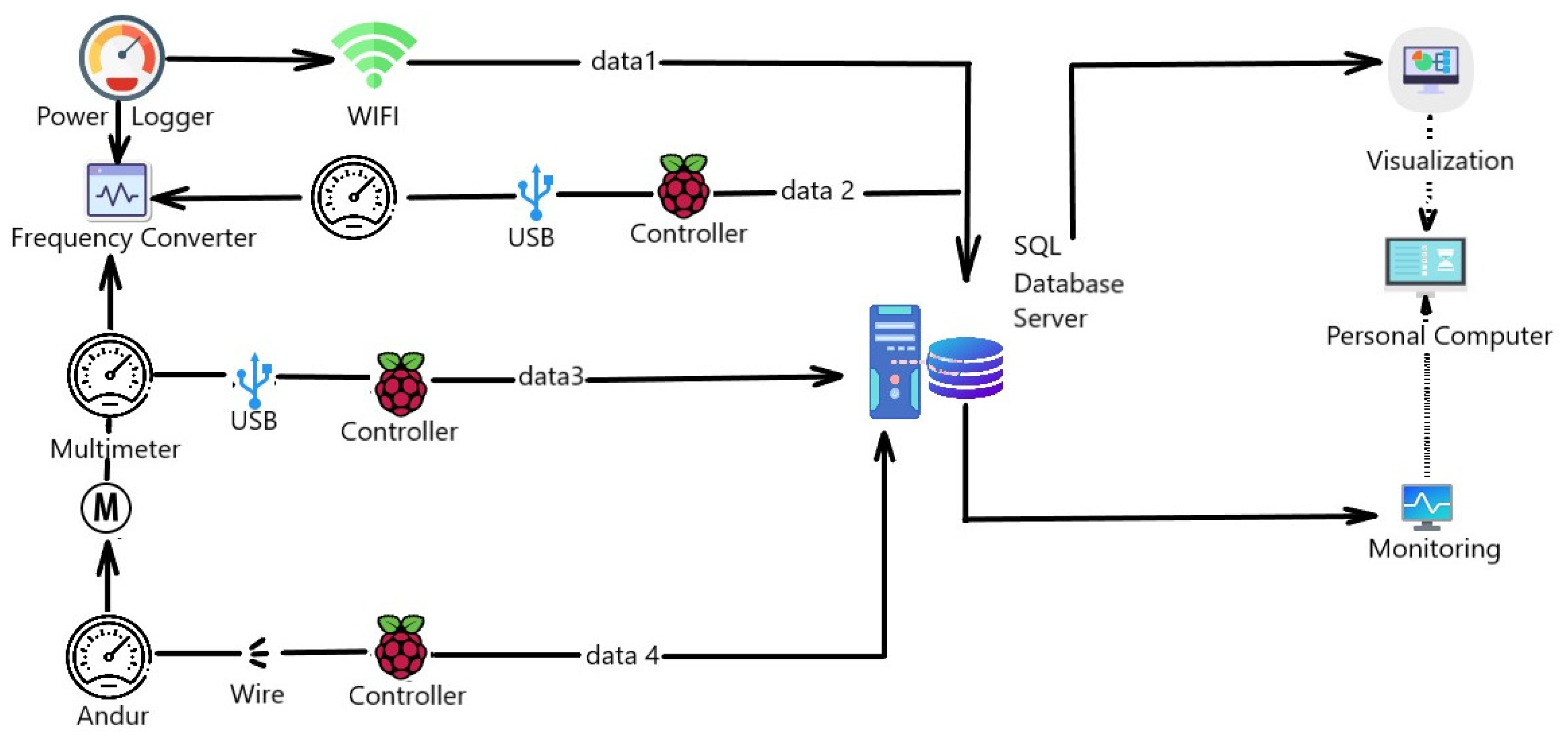
  • Introduces a technical solution for real-time monitoring involving the simultaneous measurement of input and output physical quantities. This approach overcomes the limitations of traditional diagnostic methods by addressing inaccuracies in collected data and analyzing dynamic, systematic errors due to the inertial properties of frequency converters.
  • Incorporates advanced control methods, including a vector control method with a speed control scheme, alongside standard drive frequency control methods. This contribution addresses significant nonlinearities in torque formation and optimizes frequency converter settings, improving response characteristics and overall system performance.
In the field of mechanical measurements, virtual standards for the vibration of defective bearing units have been developed [1]. Modern diagnostic equipment, based solely on data processing, only checks the functionality of technical nodes. For comprehensive diagnostics, information on both the time dependence of the signal and its spectral density is necessary to conduct complete metrological diagnostics with uncertainty evaluation of all measurements. Multifractal analysis is widely used to assess the accuracy of mechanical models and develop measurement formulas [2]. One article [5] discusses the possibilities of implementing precise measurements of passive and active electrical quantities in instrumentation. Virtual standards are being created as a special type of test signal to address many production issues. A virtual standard, such as a virtual voltage reference, is proposed in [7]. The developed dynamic model for simulating and accurately diagnosing bearing faults is presented in [8]. In many industries, such models have become an integral part of the production, maintenance, and operation of technological processes.
A test bench has been developed based on an asynchronous frequency-controlled electric drive. This electric drive includes a frequency converter, an asynchronous motor, an incremental encoder as a speed feedback sensor, and a measurement system. The mounting system for the speed sensor on the motor shaft, using Mounting Bell MG58A, Shaft Adapter WDGWA10M06, and Jointed Coupling ST27, ensures precise alignment with the motor shaft. The measurement system encompasses measuring, linking, computational components, and auxiliary devices functioning as an integrated unit. It is designed to gather information about the drive’s state, characterized by time-varying and spatially distributed parameters.
This drive is a load reference drive operating in torque control mode, generating the required torque at a specified rotational speed for transmitting torque to the tested drive system. The accuracy of torque transmission depends on statistical uncertainties, measurement instrument accuracy classes, and the driver’s condition. While good metrological equipment performance is necessary, it alone is insufficient to obtain precise output characteristics of the tested drive. The efficiency is largely determined by the data processing and analysis methods employed. The nonlinear relationship obtained for the reference drive is a measurement formula for experiment planning. The required torque is set by a voltage/current simulator meter integrated into the reference drive’s measurement system. Since a single-polarity analog signal generates torque, its sign changes with the state of the 0/1 discrete control input of the frequency drive.
The characteristics obtained in this study are sufficiently accurate for practical use, with primary control inputs in the form of real analog signals. All functions exhibit non-analytical nonlinearities derived from real operational data. Based on these results, a patent application has been submitted.

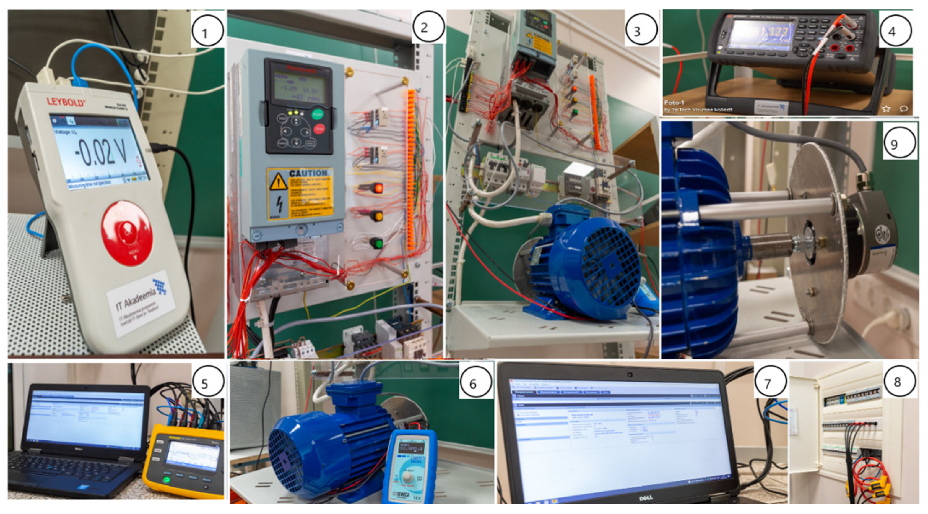
2. Experimental Setup

A dynamic model for remote control of the rotating electrical machine connected to the drive-in open loop has been created for real-time monitoring of processes. As a digital training object, the model is designed for monitoring, optimizing, and improving production processes. This physical model of an industrial device is equipped with modern sensors and web software packages. Using the created model, it is possible to simulate and identify faults and monitor the equipment’s condition in real-time.
The setup is equipped with precision measuring instruments connected to the created engineering software for timely prediction and elimination of machine part failures. Equipment condition monitoring is performed remotely by recording large amounts of data in real-time. In [9,10], the control of induction electric drives using IoT technology is analyzed. It is noted that operators can receive accurate feedback in real-time. The feedback accuracy is influenced by the dynamics of the processes in the electric drive, which depend on the inertia of the nonlinear system. The effect of the inertia of induction motor loads on system frequency stability is described in the study [11]. Figure 1 shows the illustrative scheme of the drive’s dynamic model.
At the same time, Figure 2 presents an example of an implementation that reflects the principles of real-time process monitoring, data collection, and visualization of the inertial dynamic model’s dynamics.
This includes the following components:
  • Mobile-CASSY 2 Wi-Fi.
  • VACON NX frequency converter with control panel for local/remote control applications.
  • SG 56-4A 0.06 kW three-phase induction motors.
  • Digital multimeters 34,470 A (71/2 digit).
  • Fluke 1736 power logger.
  • Test 4 signal simulator and multimeter handheld for analog signals.
  • Software for obtaining information about the state of the drive in the general case of numerous time-varying and spatially distributed quantities characterizing this state.
  • 17XX-Flex1500-12” current clamp (1500-1) A.
  • A system for mounting a speed sensor on the motor shaft using Mounting Bell MG58A, Shaft Adapter WDGWA10M06, and Jointed Coupling ST27, which ensures the possibility of monitoring the misalignment of the sensor axis with the motor axis.
One study [12] describes one of the main parts of smart grid technologies, the ripple control technology. It can be defined as a method of load control on power grids. Comparing data obtained using the Power Logger Fluke 1736 and the multimeter Keysight can help resolve the problem arising from the supply of the machines through electronic converters. When comparing the input and output electrical signals of the Vacon NX frequency converter, it is possible to assess the degree of reduced probability of detecting faults in machine parts due to higher harmonics in the signals coming from the frequency converter. The effect of synthesized higher harmonics on the network is described in the study [13]. For monitoring, all measuring instruments, signal sources, and the frequency converter are connected to the target computer through a 1TEC auto hub to a single USB port. MATLAB was used to visualize the obtained data. Synchronization of the measuring instruments was carried out in data logger mode.
The continuous operation of the dynamic model is ensured by intelligent control and engine protection, as well as the use of high-quality components and efficient cooling. The created unit is a dynamic drive model used for cargo transportation; for controlling extruders, screws and elevators; and for controlling a group of pumps and fans.

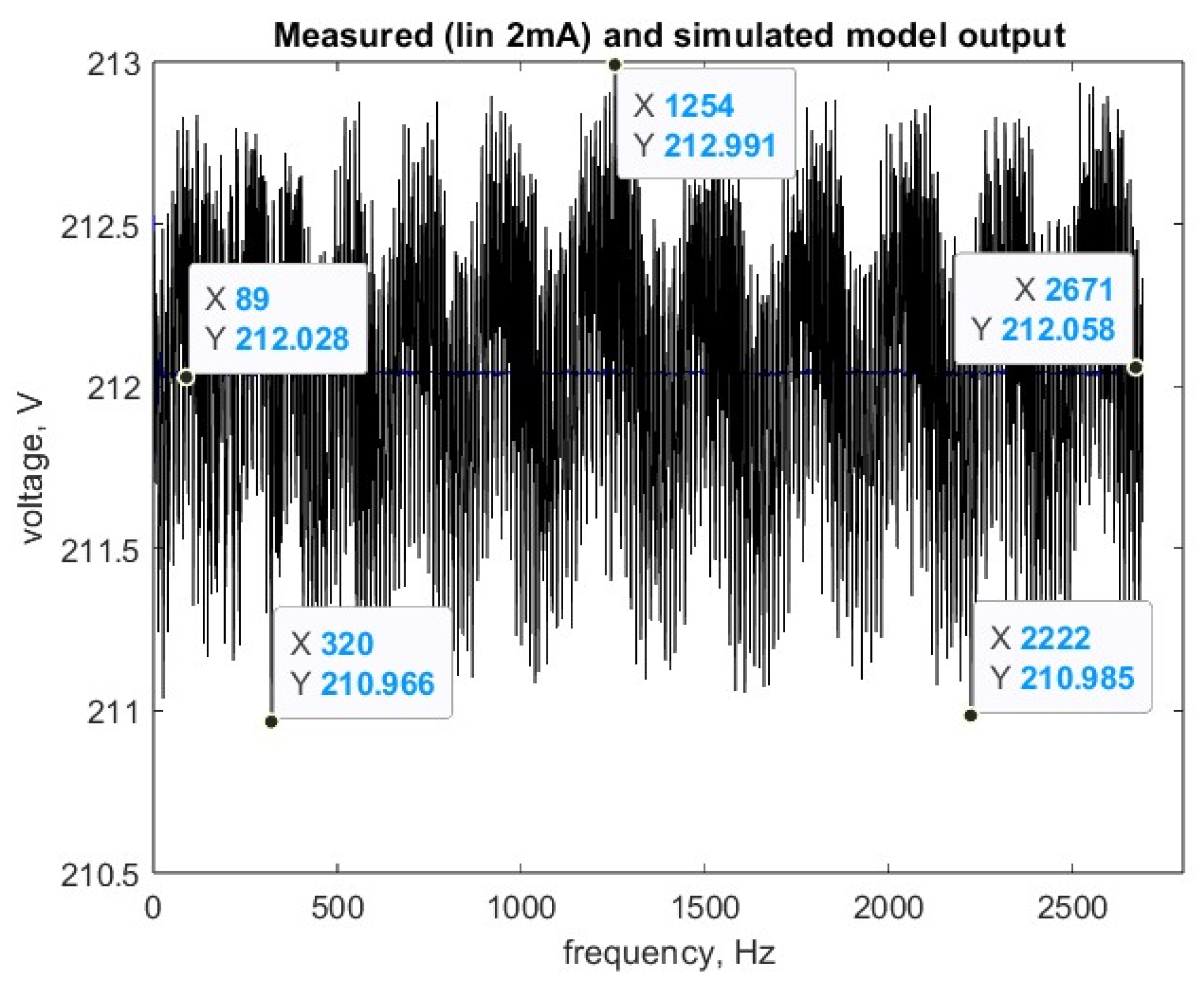
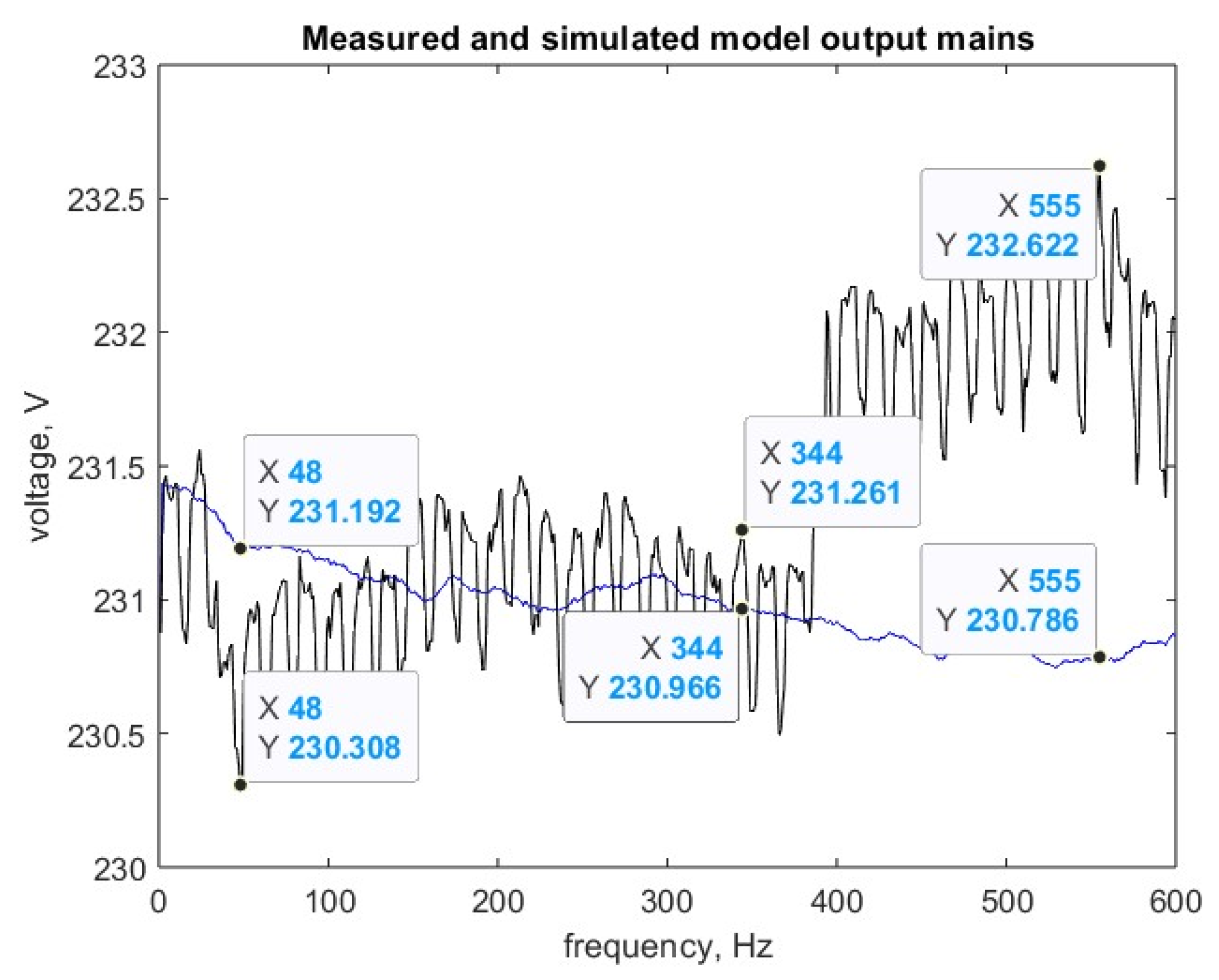
3. Experimental Verification of the Output EMC Filter

The model uses a general-purpose frequency converter, the Vacon NXS, a compact AC frequency converter. It is used for the intensive operation of induction motors. One of the key features of the reliable design of the Vacon NXS is its effective protection against power supply disturbances, as it has a built-in EMC filter. Achieving electromagnetic compatibility, which significantly improves the voltage characteristics supplied to the rotating SCIM electrical machine from the Vacon NXS converter output, is considered ineffective. There is no built-in EMC filter at the output of this frequency converter. To solve the issue of using a sine filter, which smooths the pulse-width modulated output voltage of the frequency converter to an almost sinusoidal shape, a comparison of the input and output voltage of this frequency converter is necessary. The importance of digital signal processing is discussed in the article [14].
The impact of any EMC interference on objects is determined by its entire graph; therefore, from a fundamental standpoint, continuous voltage oscillation graphs should be considered without artificially dividing them into separate sections based on one criterion or another. Then, the amplitude of voltage oscillations at the output of the frequency converter is determined. Amplitude–frequency voltage oscillations are defined [15] as the difference between the voltage and the trend, relative to the trend (Figure 3), excluding the concept of single measurements that is d U U t r e n d , which is presented in Table 1.
The drive operation process was identified as a nonlinear system using the System Identification Toolbox package. The results were analyzed using transient characteristics. The output response to input signals was determined and is shown in Figure 3, Figure 4 and Figure 5. A model was built based on real data that describe the second-order transfer function.
In the remote-controlled application mode, the analog input has a current range of 0–20 mA, corresponding to the acceleration characteristics of an asynchronous motor with a nominal rotational speed of 1400 min−1.
The value of the voltage change process was assessed during the measurement of short-term voltage fluctuations over 10 min. Figure 4 shows the amplitude of voltage oscillations at the input of the frequency converter from the EMC filter side.
In Figure 5, the amplitude of voltage fluctuations at the input of the frequency converter from the network side is presented.
The issues related to the quality of electrical energy are described in [16,17], while the stability problems of the power system are outlined in [18]. Electrical energy indicators are measured during the investigation of the dynamic model in the online mode, as shown in Figure 6.
Here, the Fluke 1736 device is managed in administration mode, which allows for screen viewing and real-time recording of physical quantities.
The magnitude of amplitude–frequency voltage fluctuations both at the input and output of the frequency converter demonstrates that the application of an output EMC filter is unnecessary, as presented in Figure 7, Figure 8, Figure 9 and Figure 10. This assertion can be validated using a model that detects the signal-to-noise ratio [19,20]. The signal-to-noise ratio (SNR), expressed in dB, allows for the determination of the proportion of noise in the measured signal relative to the useful signal. The signal-to-noise ratio and distortions were studied. Signal representation in the frequency domain reveals important signal characteristics that are difficult to analyze in the time domain.
The THD function, performing harmonic analysis, displays the total nonlinear distortions.
The SINAD (signal in noise and distortion) function performs signal analysis in noise and distortion analysis. Since the SINAD is positive, there is no total harmonic distortion.
Based on models detecting signal-to-noise ratios, it is also demonstrated that an output EMC filter is not necessary at the output of the frequency converter.

4. Mathematical Description of the Internal State of a Nonlinear System

Implemented control protects the motor from short circuits, overloads, underloads, and jamming. It includes startup control with direction and speed determination, as well as evaluation of DC and flow braking modes. Specifications are as follows:
  • Power: 3~380/500 V–0.75…400 kW.
  • Overload capacity: up to 150%.
  • Output frequency: 0…320 Hz.
  • Control method: Scalar (U/f), vector with open loop.
  • Dynamic positive feedback.
The study of a nonlinear system, in general, is a rather complex task, as it involves solving nonlinear differential equations [21,22]. The task is simplified if it is required that the nonlinear dependence of Formula (1) does not explicitly contain time [23,24]. For such a comparison, it should be noted that in nonlinear systems, the relationship between the input signal u i n ( t ) and the output response u o u t t is described by a nonlinear functional dependence:
u o u t t = f ( u i n , t )
The study of a nonlinear system is simplified if the frequency converter is considered an inertia-free nonlinear element. The external characteristics of the frequency converter are to be examined, where the input signal is the voltage at the input of the frequency converter from the EMC filter side, and the output signal is the voltage at the input of the induction electrical machine in the remote control application mode. The features are analog input, current range 0–20 mA; frequency control; U/f ratio selection-squared. We use Newton’s interpolation Formula (2):
f x = k = 0 n k f ( 0 ) k ! x ( k )
where ∆ is the primary operator in finite difference calculus. The MATLAB 2023 b program obtained a polynomial describing the nonlinear dependence of the form for the studied drive.
When transferring torque from the load reference drive to the tested drive, the task of comparing torque values is addressed. The load characteristic of the tested drive’s executive mechanism determines the relationship between shaft speed and torque. Motor shafts must be rigidly interconnected. Torque and speed values are tracked in real-time.
The accuracy of torque transmission can be determined using a model equation for practical accuracy. Such an approach is feasible only for acceleration characteristics described analytically by a quadratic torque dependence on speed. Analog signals serve as the source of the measurement signal. The model equation, in this case, takes the form
= T C + C ( T S + S + θ S )
where TC—torque value on the shaft of the tested drive, TS—torque value corresponding to the control action, ∆S—quantization error of signals during processing of control actions, θS—unexcluded systematic error of quantization during processing of control actions, and ∆C—quantization error in measuring torque on the shaft of the tested drive.
The following uncertainties correspond to the listed input quantities: u(TS)—uncertainty associated with the scattering of torque values corresponding to control actions, determined by Type A during multiple measurements, u(∆S)—uncertainty of signal quantization during processing of control actions, u(θS)—uncertainty associated with unexcluded systematic error of quantization during the processing of control actions, u(TC)—uncertainty associated with the scattering of torque values on the shaft of the tested drive, determined by Type A during multiple measurements, and u(∆C)—uncertainty of quantization in measuring torque on the shaft of the tested drive.
Since motor shafts are rigidly interconnected, simultaneous measurement of torques by identical measuring systems may exhibit an observable correlation between their readings. In this case, it is advisable to use the reduction method when processing measurement results [1]. Then, the total standard uncertainty of torque comparison is determined by the expression
u = u 2 T C T S + u 2 C + u 2 S + u 2 θ S
where u(TCTS) is the uncertainty associated with the scattering of torque differences on both the shaft of the tested drive and corresponding to the control action. This uncertainty is statistically evaluated. The expanded uncertainty is as follows:
U = t 0.95 { n 1 u u T C T S 4 } · u ( )
where n corresponds to the number of measurements.

5. Experiment on Torque Control of an Induction Motor with a Squirrel-Cage Rotor (Predictive Torque Control Technique)

One of the vector control methods for motors is the predictive torque control (PTC) technique [25,26,27,28,29,30,31,32,33,34]. In [35], a direct torque control system is proposed to save energy in drives used for moving goods. A detailed analysis of this vector control method, using Simulink and SimPowerSystems, is provided. However, standard induction motors operate with small rotor slip and maximum load. These motors have a high starting current and low starting torque, and the power supply voltage can be unbalanced. Therefore, it is crucial to investigate the real operating conditions of the drive rather than simulating operating modes.
A closed-loop speed control system for a dual-motor frequency-controlled induction drive is presented in [36]. The capabilities of the Schneider electric frequency converter determine the motor control methods studied. All measurements were performed using a two-channel digital oscilloscope Instek GDS-2062. Standard settings and measurements taken with them cannot be used to evaluate the accuracy of vector control. Additionally, ref. [36] notes that several simplifications and assumptions are used in forming the vector control theory, which is theoretically difficult to evaluate. The measurements and processing of results in this work are a step toward assessing these simplifications.
Some studies [36,37,38,39] discuss a sensorless control method for synchronous motors, induction motors, and mobile manipulators based on a sliding mode observer (SMO). The method’s effectiveness was evaluated at speeds from zero to 200 rpm.
It is known that an electric drive is a nonlinear electromechanical system. The dynamic model of the frequency-controlled drive implements a torque control mode. The torque control function, which can be used in industrial frequency converters, is analyzed. The article describes the implementation options for this function, its purpose, and parameter settings. In the dynamic model, an incremental encoder, Encoder WDGI 58A, is used as the induction motor load. These encoders are used in the industry for dynamic control and positioning of robots [40] and in variable speed wind generation systems (VS-WGSs) [41].
The encoder outputs are connected to the frequency converter powering the motor, enabling precise positioning and maintaining the required speed and torque without using a controller. This implements a dynamic, positive feedback mode, where there is no need to evaluate the rotor shaft angle accuracy, as mentioned in [23,42]. Vector control of an induction motor can also be realized this way.
Industrial frequency converters provide a set of functions to implement torque control mode. Creating the required torque is the main technological task in industrial load devices. According to the general principle of torque control function implementation in the studied model, the torque is set as a current or voltage signal to one of the analog control inputs of the frequency converter (Figure 2). A unipolar analog signal sets the required torque, implemented using Seneka Test 4.
The incremental encoder, Encoder WDGI 58A, acts as a traction load analog. Figure 11 shows the traction load torque, which depends only on speed, as the support is flat. Additional changes in torque occur with shaft misalignment using shaft adapter WDGA10M06 and couplings ST27. At near-zero speed, torque is mainly due to stickiness, which disappears at higher speeds, where viscous friction and air resistance dominate. The load torque with the potential for equilibrium operation of the motor is active, as it is maintained with changes in the motor’s rotation direction.
An analog control signal was used as the input data vector, and the angular velocity vector was recorded from the output. The time interval corresponded to the measurement system sensitivity of the investigated drive, which was 1 ms. Measurement channels were designated as current. For some input control signals, the motor did not rotate, indicating the nonlinear nature of the object being identified. This occurred due to the dry friction effect, which required the input signal to exceed a certain threshold value to overcome it. The Hammerstein–Wiener model was applied to capture the dynamics of this process. The model structure was determined: dynamic properties were described by a linear transfer function, and nonlinearity was represented by static input and output blocks. The input nonlinearity was defined as a dead zone, which is characteristic of the dry friction effect (Figure 11). This is the identification process.
Then, it is important to compare the modes of vector control with an open loop and dynamic positive feedback. In Figure 12 and Figure 13, the dead zone is shown for different current signal values applied to one of the frequency converter’s analog control inputs [43,44].
When an analog control signal is applied to the input of the variable frequency drive, the system exhibits a reaction with a dead zone. At certain current values, the motor does not rotate. This indicates the nonlinearity of the object under study.
The drive operates in dynamic, positive feedback mode when the rotor frequency and motor current have the ratio shown in Figure 14. Here, the relationship between motor current and rotor shaft speed is under constant flux. The drive operates so that the relationships shown in Figure 14 are maintained between the stator current and rotor frequency when the frequency is adjusted to control speed.
With constant flux, such a relationship between motor current and rotor speed is possible. One article [45] describes the importance of measuring motor current. Any correction of speed distortion is performed at maximum current and maximum torque, resulting in a rapid transient response.
The accuracy of the developed dynamic model for remote control of the rotating electrical machine connected to the drive-in open loop is ensured by precision measuring instruments included in the developed measurement system. This system obtained accurate information about the state of the load frequency-controlled drive. A measurement formula was derived using Newton’s interpolation Equation (2), as the created model is strictly a nonlinear physical system.
u o u t = 281,3587 0.0138 · u i n 0.0028 · u i n · u i n 1 2 + 0.0030 · u i n · u i n 1 · u i n 2 6 0.0766 · u i n · u i n 1 · ( u i n 2 ) · ( u i n 3 ) 24
The results of multiple measurements were processed with an assessment of measurement uncertainty, considering the measurement formula.

6. Conclusions

This manuscript focuses on enhancing the accuracy of dynamic models for remote control of induction motors in both closed- and open-loop speed control systems, which is crucial for successful real-time process monitoring. A proposed method discusses conducting real-time measurements of input and output physical quantities, offering a solution to overcome the limitations of traditional diagnostic methods caused by data inaccuracies. Additionally, the manuscript discusses theoretical challenges related to significant nonlinearities in torque formation processes in induction drives.
Moreover, the developed dynamic model introduces control methods, including a vector control method with a speed control scheme, alongside standard drive frequency control methods. These advancements aim to identify and address response characteristics to varying degrees of system nonlinearity, optimizing frequency converter settings for improved overall system performance.
By significantly improving dynamic model accuracy, introducing real-time monitoring techniques, and incorporating advanced control methods, this manuscript contributes to advancing the field of electromechanical systems, paving the way for enhanced precision, reliability, and efficiency in real-time process monitoring and control.
Future work will concentrate on enhancing dynamic accuracy analysis. The aim is to develop sophisticated algorithms that improve real-time data handling and precise prediction, increasing the reliability of the monitoring systems. By advancing FEM calculations, it is possible to achieve more accurate stress distribution predictions in drive structures under specific external loads, necessitating detailed boundary conditions in the models. Considering these conditions, simulations that accurately reflect real-world operating scenarios will be created. Additionally, the study will focus on collaborative calculations and verifying the models through the simulation of specific situations. These advancements will lead to more precise, reliable, and efficient monitoring systems.

Author Contributions

Conceptualization, T.B. and K.K.; methodology, T.B.; software, T.B.; validation, K.K. and V.S.; formal analysis, K.K.; investigation, T.B.; resources, V.S. data curation, T.B.; writing—original draft preparation, T.B.; writing—review and editing, K.K.; visualization, K.K.; supervision, V.S.; project administration, V.S.; funding acquisition, V.S. All authors have read and agreed to the published version of the manuscript.

Funding

This article was supported by the project “Increasing the knowledge intensity of Ida-Viru entrepreneurship” co-funded by the European Union.

Data Availability Statement

Data is contained within the article.

Conflicts of Interest

The authors declare no conflicts of interest.

References

  1. Tetter, V.Y.; Sidorov, E.N.; Sidorova, E.A. Modeling of virtual standards of vibration of defective bearing units. Meas. Tech. 2013, 56, 278–282. [Google Scholar] [CrossRef]
  2. Komshin, A.S. Mathematical modeling of measurement computational monitoring of the electromechanical parameters of turbine units by a phase chronometric method. Meas. Tech. 2013, 56, 850–855. [Google Scholar] [CrossRef]
  3. Sengamalai, U.; Anbazhagan, G.; Thamizh Thentral, T.M.; Vishnuram, P.; Khurshaid, T.; Kamel, S. Three Phase Induction Motor Drive: A Systematic Review on Dynamic Modeling, Parameter Estimation, and Control Schemes. Energies 2022, 15, 8260. [Google Scholar] [CrossRef]
  4. Udomsuk, S.; Areerak, K.; Areerak, T.; Areerak, K. Online Estimation of Three-Phase Induction Motor Parameters Using an Extended Kalman Filter for Energy Saving. Energies 2024, 17, 2115. [Google Scholar] [CrossRef]
  5. Agamalov, Y.R. Aspects of measuring harmonic signal vectors in the presence of subharmonic noise and a method for suppressing it. Meas. Tech. 2013, 56, 837–841. [Google Scholar] [CrossRef]
  6. Liu, Y.T.; Chang, K.M.; Li, W.Z. Model reference adaptive control for a piezo-positioning system. Precis. Eng. J. Int. Soc. Precis. Eng. Nanotechnol. 2010, 34, 62–69. [Google Scholar] [CrossRef]
  7. Zhang, S.; Wang, H.; Liu, T.; Yu, B.; Mou, X.; Dong, X.; Xing, Y. Dynamic Evaluation Technology of Measurement Performance Group of High Voltage Transformer Based on Virtual Standard Device. In Proceedings of the 3rd International Conference on Environmental Pollution and Governance (ICEPG 2023), Xiamen, China, 27–29 October 2023; Springer Nature: Cham, Switzerland, 2023; pp. 1205–1213. [Google Scholar]
  8. Tian, Y.; Yan, C.; Liu, Y.; Luo, W.; Kang, J.; Wang, Z.; Wu, L. Characteristics of vibration response of ball bearing with local defect considering skidding. J. Mech. Sci. Technol. 2023, 37, 156–169. [Google Scholar] [CrossRef]
  9. Valtchev, S.; Meshcheryakov, V.; Gracheva, E.; Sinyukov, A.; Sinyukova, T. Energy-Saving Control for Asynchronous Motor Motion System Based on Direct Torque Regulator. Energies 2023, 16, 3870. [Google Scholar] [CrossRef]
  10. Kodkin, V.L.; Baldenkov, A.A. Experimental Studies of the Processes of Stepped Torque Loads Parrying by Asynchronous Electric Drives and Interpretation of Experimental Results by Nonlinear Transfer Functions of Drives. Processes 2022, 10, 1204. [Google Scholar] [CrossRef]
  11. Wang, Y.; Wang, X.; Xie, W.; Dou, M. Full-Speed Range Encoderless Control for Salient-Pole PMSM with a Novel Full-Order SMO. Energies 2018, 11, 2423. [Google Scholar] [CrossRef]
  12. Guidelines for the Measurement Method of Nonlinearity for Surface Acoustic Wave (SAW) and Bulk Acoustic Wave (BAW) Devices in Raadio Frequency (RF). Available online: https://standards.iteh.ai/catalog/standards/iec/c166a77a-9d03-4793-9a33-2f6e9359ca30/iec-62761-2014 (accessed on 19 February 2014).
  13. Ioannides, M.G.; Stamelos, A.P.; Papazis, S.A.; Stamataki, E.E.; Stamatakis, M.E. Internet of Things-Based Control of Induction Machines: Specifics of Electric Drives and Wind Energy Conversion Systems. Energies 2024, 17, 645. [Google Scholar] [CrossRef]
  14. Gnaciński, P.; Pepliński, M.; Muc, A.; Hallmann, D.; Jankowski, P. Effect of Ripple Control on Induction Motors. Energies 2023, 16, 7831. [Google Scholar] [CrossRef]
  15. Algburi, R.N.A.; Gao, H. Health Assessment and Fault Detection System for an Industrial Robot Using the Rotary Encoder Signal. Energies 2019, 12, 2816. [Google Scholar] [CrossRef]
  16. Zhao, X.; Qin, P.; Tang, Z. Equivalent Inertia Estimation of Asynchronous Motor and Its Effect on Power System Frequency Response. Energies 2022, 15, 8350. [Google Scholar] [CrossRef]
  17. Singh, R.R.; Chelliah, T.R. Enforcement of cost-effective energy conservation on single-fed asynchronous ma-chine using a novel switching strategy. Energy 2017, 126, 179–191. [Google Scholar] [CrossRef]
  18. Ioannides, M.G.; Koukoutsis, E.B.; Stamelos, A.P.; Papazis, S.A.; Stamataki, E.E.; Papoutsidakis, A.; Vikentios, V.; Apostolakis, N.; Stamatakis, M.E. Design and Operation of Internet of Things-Based Monitoring Control System for Induction Machines. Energies 2023, 16, 3049. [Google Scholar] [CrossRef]
  19. El-Kharashi, E.; Massoud, J.G.; Al-Ahmar, M.A. The impact of the unbalance in both the voltage and the frequency on the performance of single and cascaded induction motors. Energy 2019, 181, 561–575. [Google Scholar] [CrossRef]
  20. Cai, Z.; Liu, L.; de Paulis, F.; Qi, Y. Passive Intermodulation Measurement: Challenges and Solutions. Engineering 2022, 14, 181–191. [Google Scholar] [CrossRef]
  21. Lei, N.; An, D.; Guo, Y.; Su, K.; Liu, S.; Luo, Z.; Yau, S.T.; Gu, X. A Geometric Understanding of Deep Learning. Engineering 2020, 6, 361–374. [Google Scholar] [CrossRef]
  22. Yang, T.; Wang, T.; Miao, Y. Active decoupling control of the three-phase voltage source converter under nonlinear AC current. J. Power Electron. 2024, 24, 1–14. [Google Scholar] [CrossRef]
  23. Paramo, G.; Bretas, A.; Meyn, S. Research Trends and Applications of PMUs. Energies 2022, 15, 5329. [Google Scholar] [CrossRef]
  24. Bartels, J.-H.; Xu, R.; Kang, C.; Herrmann, R.; Marx, S. Experimental Investigation on the Transfer Behavior and Environmental Influences of Low-Noise Integrated Electronic Piezoelectric Acceleration Sensors. Metrology 2024, 4, 46–65. [Google Scholar] [CrossRef]
  25. Bedida, T.; Makhloufi, S.; Bekakra, Y.; Kermadi, M.; Bessous, N.; Kechida, R.; Taibi, D. Predictive torque control of induction motor for rotor bar faults diagnosis. Energy Rep. 2024, 11, 4940–4956. [Google Scholar] [CrossRef]
  26. Hassan, M.; Ge, X.; Woldegiorgis, A.T.; Mastoi, M.S.; Atif, R.; Shaikh, M.S.; Kumar, S. A look-up table-based model predictive torque control of IPMSM drives with duty cycle optimization. ISA Trans. 2023, 138, 670–686. [Google Scholar] [CrossRef] [PubMed]
  27. Aissa, O.; Reffas, A.; Krama, A.; Benkercha, R.; Talhaoui, H.; Abu-Rub, H. Advanced direct torque control based on neural tree controllers for induction motor drives. ISA Trans. 2024, 148, 92–104. [Google Scholar] [CrossRef]
  28. Sahu, A.; Mohanty, K.B.; Mishra, R.N. Development and experimental realization of an adaptive neural-based discrete model predictive direct torque and flux controller for induction motor drive. Appl. Soft Comput. 2021, 108, 107418. [Google Scholar] [CrossRef]
  29. Sivaraju, S.; Senthilkumar, T.; Sankar, R.; Anuradha, T.; Usha, S.; Bin Musirin, I. Improving the efficiency of induction motor drive by flux and torque control: A hybrid LSE-RERNN approach. ISA Trans. 2024, 147, 215–226. [Google Scholar] [CrossRef]
  30. Mahfoud, S.; El Ouanjli, N.; Derouich, A.; El Idrissi, A.; Hilali, A.; Chetouani, E. Higher performance enhancement of direct torque control by using artificial neural networks for doubly fed induction motor. E-Prime Adv. Electr. Eng. Electron. Energy 2024, 8, 100537. [Google Scholar] [CrossRef]
  31. Boyar, A.; Kabalci, E.; Kabalci, Y. Sensorless speed controller of an induction motor with MRAS-based model predictive control. Comput. Electr. Eng. 2024, 118, 109350. [Google Scholar] [CrossRef]
  32. Chen, H.; Zhao, J.; Wang, H.; Zhang, Q.; Luo, X.; Xu, H.; Xiong, Y. Multi-objective optimum design of five-phase squirrel cage induction motor by differential evolution algorithm. Energy Rep. 2022, 8, 51–62. [Google Scholar] [CrossRef]
  33. Agapiou, J.S. Filling Friction Stir Welding In-Process Exit Holes in Copper Squirrel Cage Rotors for Electric Motors. Procedia Manuf. 2021, 53, 802–813. [Google Scholar] [CrossRef]
  34. Szántó, A.; Ádámkó, É.; Juhász, G.; Sziki, G. Simultaneous measurement of the moment of inertia and braking torque of electric motors applying additional inertia. Measurement 2022, 204, 112135. [Google Scholar] [CrossRef]
  35. Abdelrahem, M.; Hackl, C.M.; Rodríguez, J.; Kennel, R. Model Reference Adaptive System with Finite-Set for Encoderless Control of PMSGs in Micro-Grid Systems. Energies 2020, 13, 4844. [Google Scholar] [CrossRef]
  36. Albrecht, C.; Klöck, J.; Martens, O.; Schumacher, W. Online Estimation and Correction of Systematic Encoder Line Errors. Machines 2017, 5, 1. [Google Scholar] [CrossRef]
  37. Gudiño-Ochoa, A.; Jalomo-Cuevas, J.; Molinar-Solís, J.E.; Ochoa-Ornelas, R. Analysis of Interharmonics Generation in Induction Motors Driven by Variable Frequency Drives and AC Choppers. Energies 2023, 16, 5538. [Google Scholar] [CrossRef]
  38. Nguyen-Vinh, Q.; Pham-Tran-Bich, T. Direct torque control of induction motor based on slidingmode. Electr. Eng. 2024, 106, 1–13. [Google Scholar] [CrossRef]
  39. Korayem, M.H.; Dehkordi, S.F.; Ghobadi, N. Wheel Slippage Compensation in Mobile Manipulators Through Combined Kinematic, Dynamic, and Sliding Mode Control. Arab. J. Sci. Eng. 2024, 49, 1–21. [Google Scholar] [CrossRef]
  40. Rodrigues, N.M.; Janeiro, F.M.; Ramos, P.M. Power Quality Transient Detection and Characterization Using Deep Learning Techniques. Energies 2023, 16, 1915. [Google Scholar] [CrossRef]
  41. Kumar, R.R.; Andriollo, M.; Cirrincione, G.; Cirrincione, M.; Tortella, A. A Comprehensive Review of Conventional and Intelligence-Based Approaches for the Fault Diagnosis and Condition Monitoring of Induction Motors. Energies 2022, 15, 8938. [Google Scholar] [CrossRef]
  42. Machado, J.P.Z.; Thaler, G.; Pacheco, A.L.S.; Flesch, R.C.C. Impact of Angular Speed Calculation Methods from Encoder Measurements on the Test Uncertainty of Electric Motor Efficiency. Metrology 2024, 4, 164–180. [Google Scholar] [CrossRef]
  43. Sun, G.; Ren, X.; Chen, Q.; Li, D. A modified dynamic surface approach for control of nonlinear systems with unknown input dead zone. Int. J. Robust Nonlinear Control. 2013, 23, 1145–1167. [Google Scholar] [CrossRef]
  44. Wang, Y.; Chen, Z.; Sun, M.; Sun, Q. A novel implementation of an uncertain dead-zone-input equipped extended state observer and sign estimator. Inf. Sci. 2023, 626, 75–93. [Google Scholar] [CrossRef]
  45. Kołodziejek, P.; Wachowiak, D. Fast Real-Time RDFT- and GDFT-Based Direct Fault Diagnosis of Induction Motor Drive. Energies 2022, 15, 1244. [Google Scholar] [CrossRef]
Figure 1. Drive training device.
Energies 17 03265 g001
Figure 2. The rotating SCIM electrical machine is connected to the drive-in open-loop control.
Energies 17 03265 g002
Figure 3. Measured u o u t ( f ) and simulated model output, where the analog input is 0–20 mA.
Energies 17 03265 g003
Figure 4. Measured u i n ( f ) and simulated model output, where the analog input is 2 mA.
Energies 17 03265 g004
Figure 5. Measured u i n ( f ) and simulated model output, where the analog input is 2 mA.
Energies 17 03265 g005
Figure 6. Indicators of electrical energy during the measurement of short-term voltage fluctuations.
Energies 17 03265 g006
Figure 7. THD functions, SNR of signal u i n ( f ) .
Energies 17 03265 g007
Figure 8. THD functions, SNR of signal u o u t ( f ) .
Energies 17 03265 g008
Figure 9. SINAD function of signal u i n ( f ) .
Energies 17 03265 g009
Figure 10. SINAD function of signal u o u t ( f ) .
Energies 17 03265 g010
Figure 11. The curve of rotation speed versus loading torque in steady state.
Energies 17 03265 g011
Figure 12. Dead zone of the drive in dynamics positive feedback mode: isnlarx(current1, [110])=2.2696; isnlarx(current2, [110])=7.3736; isnlarx(current3, [110])=29,429; isnlarx(current4, [110])=40.69.
Energies 17 03265 g012
Figure 13. Dead zone of the drive in open-loop vector control mode: isnlarx(current, [110])=0.5; isnlarx(current2, [110])=2.2776; isnlarx(current3, [110])=1.9611; isnlarx(current4, [110])=1.6165.
Energies 17 03265 g013
Figure 14. The curve of the dependence of motor current on rotor speed.
Energies 17 03265 g014
Table 1. Concept of single measurements.
Voltage Fluctuations u i n ( f ) from the Filter Side u i n ( f ) from the Network Side u o u t ( f ) on the Stator Winding
d U U t r e n d 0.0048 ± 0.00200.0044 ± 0.00330.0049 ± 0.0026
Disclaimer/Publisher’s Note: The statements, opinions and data contained in all publications are solely those of the individual author(s) and contributor(s) and not of MDPI and/or the editor(s). MDPI and/or the editor(s) disclaim responsibility for any injury to people or property resulting from any ideas, methods, instructions or products referred to in the content.

