Article

An iPWR MELCOR 2.2 Study on the Impact of the Modeling Parameters on Code Performance and Accident Progression

by
Mateusz Malicki
1,*,
Piotr Darnowski
2,† and
Terttaliisa Lind
1
1
Paul Scherrer Institut, Forschungsstrasse 111, 5232 Villigen, Switzerland
2
Institute of Heat Engineering, Warsaw University of Technology, Nowowiejska 21/25, 00-665 Warsaw, Poland
*
Author to whom correspondence should be addressed.
Work performed during scientific visit at Paul Scherrer Institut Division of Nuclear Energy and Safety.
Energies 2024, 17(13), 3279; https://doi.org/10.3390/en17133279
Submission received: 15 March 2024 / Revised: 18 June 2024 / Accepted: 20 June 2024 / Published: 4 July 2024
(This article belongs to the Section B4: Nuclear Energy)

Abstract

:
This paper presents the results of a severe accident parametric sensitivity study performed on a model of a generic integral pressurized water reactor (iPWR). The analyzed sequence is a loss of coolant accident (LOCA)-type scenario, postulating that safety systems are not available. In this work, a MELCOR 2.2 input deck of a generic iPWR was developed based on publicly available data. The iPWR used in this work is a generic iPWR with a thermal power of about 160 MWth, characterized by a compact steam generator and a submerged containment configuration. A hypothetical scenario considered in this work was an unmitigated small break LOCA leading to a severe accident with partial core degradation, due to the postulated assumptions. In the presented paper, 16 sensitivity cases were calculated and analyzed, focusing mainly on heat transfer, decay heat, and core degradation parameters. The selected parameters and their combination caused partial core degradation and showed significant differences in investigated variables such as core degradation and hydrogen generation, as well as examined CPU time consumption. This a preparatory work performed in the framework of the Horizon Euratom SASPAM-SA project, which aims to investigate the applicability and transfer of the operating large light-water reactor knowledge and know-how to the iPWR, taking into account European licensing analysis needs for the severe accident and emergency planning zone.

1. Introduction

Due to the recent increase in interest in nuclear technologies, including SMRs (small modular reactors), many countries have started considering new builds in the short- and mid-term. In large-scale nuclear power plants (NPPs), the challenges are relatively well known and focus more on the investment’s construction time, supply chain, or financial aspects. For SMRs, challenges are slightly different and are at another stage of technology implementation, including licensing. The International Atomic Energy Agency (IAEA) published a booklet pointing out several designs being developed worldwide with different technologies. The PWR and BWR seem more advanced and ready for deployment, but non-light-water technologies are also under development [1]. Integral pressurized water reactors (iPWRs) and small BWRs are ready to be licensed as new builds because they incorporate well-proven and established large light-water reactor (LWR) technology, along with the operational plant experience/feedback established for this technology, while including moderate evolutionary design modifications to increase the inherent safety of the plant with the use of passive systems.
The use of passive systems, the integral design, and the relatively lower core power give iPWRs a lower core damage frequency (CDF). However, due to extremely high safety standards in the nuclear industry, despite the low CDF, independent features for preventing and mitigating a severe accident sequence have to be included in the design. Therefore, some scenarios that could lead to severe accidents need to be postulated and deterministically studied. The passive systems are, on one hand, advanced solutions to increase the safety of the plant (e.g., there is no need of a pump); on the other hand, (a) they require more investigation in terms of assessing the functional failure related to the thermal-hydraulic phenomena driving the operation of the systems and the related uncertainties, (b) they may still need an active initiation, and (c) they are characterized by less operational experience (see [2,3] for more detailed information). Considering these factors, and the uncertainties in severe accident progression analyses, the advanced features (e.g., passive systems) need to be studied and their impact on the severe accident scenario assessed. Also, codes used for deterministic analysis in current large-scale reactors need to be challenged, using SMR modeling, to find their potential limitations or gaps due to specific design peculiarities, e.g., coolant circulation between the reactor and containment pressure vessels or compact steam generators (SGs) [4]. These kinds of analyses will lead, if needed, to improvements in the codes and an enhancement of the analytical experience, which will help to fulfill the highest nuclear safety standards. That is why analyses of new features, especially passive ones, should also be undertaken by independent analysts and should include the use of different codes [5], and should preferably involve the running of multiple cases of sensitivity and uncertainty quantification analyses [6]. Investigation of the passive system’s operation under accident conditions, including severe accidents, also helps to highlight the differences between SMRs and large NPPs which have already been identified by other researchers [7]. This study, as such, should positively affect SMR’s future operation, numerical simulations, and accident management. With regard to this, the identification of the conditions in the reactor pressure vessel (RPV), and in the containment vessels that characterize iPWR scenarios, might differ significantly from those that would apply to a large-scale LWR, and the study of this is also one of the goals of the Horizon Euratom Safety Analysis of SMRs in the Passive Mitigation Strategies–Severe Accident (SASPAM-SA) project. The research presented in this paper is a part of the PSI contribution to SASPAM-SA [8].
In this paper, the authors focus on simulating the iPWR severe accident scenario with the MELCOR computer code version 2.2.18019. MELCOR is an integral severe accident code developed by Sandia National Laboratories (SNL) and founded by the U.S. NRC (Nuclear Regulatory Commission). It is widely used for severe accident simulation and analyses of PWR and BWR NPPs, spent fuel pools, experimental facilities, and some GEN-IV reactors. MELCOR developers constantly update the code, meeting the needs of the industry and user community, and adding dedicated models in accordance with current needs, e.g., the helical steam generator (HSG) for SMR modeling [9,10].
Despite the efforts of the developers, simulating passive systems can be challenging when performing integral code modeling. All uncertainties related to severe accidents and passive system’s operation in transient conditions motivate the authors to perform several parametric sensitivity studies to gain knowledge about severe accident code limits and potentially identify the need for future improvements, which is one of the main goals of the SASPAM-SA. The potential challenges in iPWR modeling can come from the specific phenomena that characterize SMR and that need further validation activity. In such cases, performing sensitivity and uncertainty analyses could be crucial for the safety assessment of the considered design as it helps to interpret the obtained results more consciously. Natural convection, which is the fundamental of iPWR safety, is a passive solution (by design) that should work independently from the availability of the power supply or human actions. However, convection forces responsible for the coolant circulation could be disturbed under unexpected conditions, which could especially occur during severe accidents. Considering the code uncertainties and the potential sensitives of natural circulation due to unforeseen conditions, the authors investigated the impact of specific parameters on cooling efficiency and code capability to capture the effect of these parameter variations.
This paper presents a parametric sensitivity study focusing on core heat transfer parameters in the iPWR generic plant. The main concern was the modeling of heat transfer from the core to the surrounding structures such as the bypass, core barrel, and downcomer, as well as the core degradation parameters. The purpose of it lies in the passive nature of iPWRs and in natural circulation, which plays the main role not only during normal operation but also during severe accidents. In similar studies by other authors, heat transfer through the core barrel was pointed out to be the main way of heat evacuation from the core to the RPV [11]. The radial heat transfer from the core could also be a factor in the natural circulation instabilities that were identified in SMR numerical simulations [12,13,14]. The investigated variables focus on core degradation parameters, hydrogen production, and basic thermal hydraulics.
This study is performed in the frame of SASPAM-SA Work Package 2 (WP2), which focuses on identifying plausible severe accident sequences for the target generic iPWR designs that will be used within the SASPAM-SA project to test/benchmark/assess the applicability and modeling capability of severe accident codes, such as MELCOR, for LW-SMRs.
The paper is divided into six chapters: introduction to the topic, SASPAM-SA project description, explanation of generic iPWR model, parametric sensitivity study, results discussion, and summary.

2. SASPAM-SA Project

There is a growing interest in deploying SMRs, and several activities are underway in many countries to prepare for possible licensing needs. Despite the reinforcement of the first three levels of defense-in-depth (DiD), a sound demonstration of the ability of the safety systems in an iPWR to respond to transient, potentially leading to severe, accidents should be carried out (DiD levels 4–5, [2,15]). In this context, the key objective of the SASPAM-SA project is to investigate the applicability and transfer of the knowledge and know-how from operating large-scale LWR reactors to the near-term deployment of iPWRs, in view of the European licensing analyses needs related to severe accident and emergency planning zones. The project’s key outcome is to support the iPWR licensing process by bringing up key elements of the safety demonstration needed and speeding up the licensing and siting process of iPWRs in Europe. The SASPAM-SA project proposal was funded by HORIZON-EURATOM-2021-NRT-01-01, “Safety of operating nuclear power plants and research reactors”, and the ENEA coordinates it. Twenty-three organizations from fourteen countries are involved.
In order to maximize the knowledge transferability and impacts of the project, two generic design concepts, characterized by different evolutionary innovations in comparison to larger operating reactors, have been selected for the analyses. These two generic reactor concepts include the main iPWR design features, which are considered the most promising designs for the European market, allowing us to assess in a wider way the capability of codes (SA and CFD) to simulate the phenomena typical of iPWRs [16]. It is not the SASPAM-SA project’s objective to assess the generic reactor designs selected but, based on the project findings, it allows for a more general statement on the capability of the codes to simulate postulated SA conditions in iPWRs [17].

3. Generic iPWR Model

The study presented here was performed in the frame of the WP2, “Input deck development and hypothetical SA scenarios assessment (SCENARIOS)”, coordinated by the Karlsruhe Institute of Technology (KIT), in which the main goal is developing a generic iPWR input deck using SA codes (here MELCOR 2.2) and analyze the iPWR response to various hypothetical postulated severe accident scenarios.
The studied plant is a generic iPWR with thermal power of about 160 MWth and characterized by a compact steam generator (SG) and a submerged containment configuration (in SASPAM-SA called design one); see Figure 1. Even though design one is generic, it includes some of the features of advanced LW-SMR concepts, such as integral RPV, compact SG, and primary/containment coupling. This, in view of possible European SMR licensing needs, allows us to assess the capability of codes (severe accident code and CFD) to simulate the phenomena typical of iPWRs with these features and identify code development needs.

3.1. Detailed Description of the Generic iPWR Studied

The generic iPWR investigated here has 160 MWth power and is equipped with compact helical SGs loops. The reactor pressure vessel (RPV) contains all essential elements of the reactor coolant system (RCS), such as the core, the pressurizer (PRZ), the primary side of SG, and the downcomer. Due to integral design, there is no hot or cold leg, which eliminates the possibility of large break LOCA (LBLOCA) and, therefore, eliminates some of the possible severe accident scenarios, e.g., unmitigated LBLOCA. The integral design presented here relies only on passive systems, convection, conduction, and natural circulation. There are no pumps or active systems on the primary side. The RPV is placed inside a second containment pressure vessel. The containment vessel’s initial condition is postulated in this study without water, in subatmospheric pressure, and it is submerged in a reactor pool (RP) placed inside a reactor building (RB). The generic design considered has a set of valves as a safety system called the emergency core cooling system (ECCS). In this study, the ECCS is a system composed of two groups of valves allowing coolant circulation between the RPV and the containment vessel during accident conditions. One group of valves is placed on the top of the PRZ and are called reactor ventilation valves (RVV), and the second group is placed slightly above the active core and are called the reactor recirculation valves (RRV).
This configuration allows a LOCA mitigation based on a natural circulation primary/containment coupling: for a design basis event, in fact, the steam produced in the core travels along the ascending riser and exits through the PRZ valves (RVV). The steam is condensed on the inside surface of the containment vessel, then accumulates at the bottom of the containment vessel, and liquid is then returned to the RPV via RRV. The energy from the containment vessel is removed to the RP, which acts as an ultimate heat sink (UHS). More details on primary/containment coupling in a reactor with a submerged containment vessel and the related experimental characterization are publicly available to the international community, and are in [18,19].

3.2. MELCOR Input Deck

The MELCOR 2.2 input deck of the iPWR was developed based on the SASPAM-SA database, which was built based on publicly available information or the engineering assumptions summarized in [8,16,17]. This work will study LOCA-type accidents to examine code capabilities and the impact of the selected parameters on the quick depressurization sequence. For most of the necessary parameters, the authors tried to follow MELCOR best practices and guidelines [9,20,21,22], and if there were no strict guidelines about component modeling, engineering judgment was used to achieve the requested steady-state outcome and system stability. The input deck could be considered as a fine nodalization, complex model for relatively small geometry; it contains 79 control volumes (CVH), 116 flow paths (FL), and 62 heat structures (HS). To properly simulate steady-state and accident conditions, 256 control systems were used, including control functions (CF) and tabular functions (TF). The MELCOR model mimics the geometry of design one (and it is divided into four main areas: RPV, containment vessel, RP, and RB), which was also used by other researchers [23]; see Figure 1 and Figure 2. The input deck uses the eutectic model and the radionuclide (RN) package. The decay heat was defined based on the ANS 73 decay heat standard, scaled down to the investigated iPWR power.
The COR package divides the core region into nine axial levels, (levels from five to eight are active). The lower levels are dedicated to the lower plenum, while the highest level simulates the upper plate and assembly structures. Radially, the COR is divided into four rings, of which rings one to three are active. The thermal hydraulic (TH) part of the core input deck is divided into six CVHs for the active part and two for the non-active (bypass); see Figure 2. The coolant flows out from the core to the raiser due to natural convection. From the raiser, coolant can reach the PRZ, which is on the top of the integrated RPV, or it can flow down through the primary side of the helical SG to the downcomer. The secondary side of the SG is modeled as a two-loop heat exchanger that surrounds the riser. The downcomer is a natural continuation of the downstream flow from the primary side of the helical SG, which surrounds the core and, on the bottom, enters the lower plenum where the coolant is mixing and goes back to the core, closing the loop of natural circulation.
The helical SGs are modeled by 7 CVHs per loop (14 CVH in total; see Figure 2) and can exchange the heat with the primary side of the SG via HS. For the external part of the SG HS, the Zukauskas correlation is used as it is dedicated to perpendicular flow heat exchange. For the internal part of the SG HS, the helical SG heat exchange-correlation is used, which is also dedicated to this type of geometry and was recently implemented by the MELCOR developers. The feed water is defined as a time-independent CVH, and the mass flow rate is regulated according to the water level in SG channels to achieve the requested steady-state conditions. Steam line, similar to feed water, is represented as a constant CVH.
The RPV is connected to the containment by a set of safety related valves. Three valves on the top of the PRZ are RVV, which aim to vent steam from the RPV to the containment in case of an accident and also to decrease pressure in the primary circuit. The evacuated steam that condenses inside of the containment causes a collection of condensate in the bottom of the containment vessel. During accident conditions, the water level in the containment vessel should reach the two RRVs, which allows coolant to circulate back from the containment vessel to the RPV. The RRVs are placed slightly above the active core. The RVV and RRV together are parts of the ECCS. The RPV is also connected thermally to the containment vessel via the HSs. The containment vessel during normal operation is postulated empty and under extremely low pressure, which isolates the RPV from the pool, decreasing heat losses. Containment is modeled by 12 CVHs (see Figure 2), which are thermally connected to the RPV (from the one side) and to the RP (from the other side). The containment vessel is submerged in the RP and is connected to it only thermally by the HSs (no valves, leaks, or other mass transfer between containment and RP is modeled). The RP is divided into eight CVHs to allow natural circulation of the water. The input deck contains concrete HSs that mimic the pool floor and walls. The RP is open to the RB, which is under normal conditions as it is also open to the environment. The environment is modeled as a time-independent (constant), CVH. No additional HSs are used in the RB as the potential phenomena that occur there were not a part of this investigation.

4. Parametric Sensitivity Study

In the presented study, the authors focused on heat transfer around the core region and on the core parameters, which could impact the coolability of the degraded core. The primary motivation to focus on that part of the model was due to the natural circulation of the coolant (core coolability) and the potential flow disruption in the downcomer caused by heat transfer from the core to the surrounding structures and volumes. The analyzed scenario, assumptions, and sensitivity parameters are hypothetical, and have been selected to explore the code capabilities and limitations in the simulation of the entirely passive integrated system, as presented here: the iPWR. The primary motivation is to gain knowledge about the potential modeling issues, which could help other analysts with modeling in future work and help code developers working on further code improvement.

4.1. Studied Accident Sequence and Assumptions

In all the analyzed cases, a 5000 s steady state was calculated before the postulated initiating event (PIE), which occurs at 0.0 s of the analyzed scenarios. The PIE is a station black out (SBO) (a spontaneous opening of the one RVV (SBLOCA)), and it is postulated that the remaining ECCS valves are stuck closed. The feedwater and steam line were successfully isolated, and there was a successful SCRAM.
In this scenario, i.e., unmitigated RVV-LOCA, the coolant evacuates through a stuck open RVV. The severe assumptions finally led to the core being uncovered, and to its partial degradation due to insufficient cooling.
The reference case was defined, and, in this work, it is abbreviated as F5. It is a best estimate input deck where authors use the values and parameters proposed by the code developers for PWR in the MELCOR manuals [10,23] or the MELCOR best practices guidelines [9]. The F5 was used as a starting point for our parametric sensitivity study, in which 11 cases were considered; see Section 4.2. Additionally, 4 cases, combining some previously tested parameters, were calculated, and analyzed; see Section 4.3. All input variations are described below in Section 4.2 and Section 4.3, and, if it is not stated any other way, the changes are made for reference case F5.

4.2. Studied Parameters and Calculated Cases

In this work, the authors focused on the heat transfer from the core to the surroundings. The main motivation to work on that topic was the passive nature of the RCS, which strongly relies on how efficiently energy is transferred to the coolant and where it is transferred (e.g., bypass, core barrel, or downcomer). Heat transfer distribution could impact natural circulation by decreasing or increasing convection and, consequently, mass flow rate through the core and core water levels. The studied sensitivity cases are summarized in Table 1.
The first sensitivity case (F5a) has modified thermal conductivity for crucial heat structures—the core barrel, RPV, and containment vessel. The default code’s (generic) stainless steel was applied, and its thermal conductivity was reduced to 80% of the original value. The direct motivation was to reduce the heat removal capabilities of the system and make core degradation more likely. This modeling can mimic the impairment of heat transmission due to various other mechanisms. This approach was inspired by SNL’s high temperature gas-cooled reactors (HTGR) study, where the authors studied even a 50% reduction in conductivity for graphite [24]. The importance of graphite for an HTGR is, to some extent, similar to the importance of steel in iPWRs. However, in this study, based on engineering judgment, the 20% reduction was assessed to be a sufficient assumption.
The second and third cases have increased decay heat equal to 120%. The F5b has higher decay heat during steady-state and transient state with conserved total power. In effect, the radionuclide inventory is higher than normal. The F5c is a case with decay heat given by the table, with decay heat increased only during the transient state and with the radionuclide inventory corresponding to the normal state. First of all, the motivation was that the higher decay heat during the transient state should lead to different progression of the in-vessel phenomena. The other motivation was to show the possible influence of the higher inventory of radionuclides, which are distributed in the system during an accident.
Sensitivity models F5d–F5f were developed to investigate the impact of modified heat transfer paths on the heat transfer from the core to the surrounding structures. Parameter selection was motivated by previous research [25]. In the basic model (F5), the core bypass control volume (see Figure 2) is in thermal contact with the core barrel, and then heat is transferred to the downcomer. The F5d case has changed boundary conditions for the core barrel heat structure, and heat is transferred directly from core control volumes to the downcomer. Differently, cases F5e and F5f have the core barrel heat transfer scaling factors increased (by 50%) or decreased (by 30%). It includes modification of the radiative and atmosphere heat transfer scaling factors for the external and internal sides of the core barrel—as indicated in Table 1. These three cases were prepared to investigate the impact of core barrel heat transfer. First of all, it can be expected that increased heat transfer will reduce the negative effects of the accident. However, it may also lead to preheating of the water in the downcomer, disturbance in the natural circulation of gases (or water), and could have a potential impact on the degradation phenomena. The outcome was not obvious, and this effect was studied.
The next two cases, F5g and F5h, have their debris porosity reduced to 30% and increased to 50%. This parameter in a similar range was also studied by other researchers [26,27,28]. Both can lead to various effects. The reduced porosity leads to higher flow blockage, reducing heat removal by convection and escalating temperature. It can result in higher oxidation due to higher temperatures, but it can also reduce the oxidation rate due to lower steam availability and, in effect, cause a lower heat generation rate. Increased porosity might improve heat removal by fluids and convection, but it might also lead to enhanced oxidation due to easier access to non-oxidized hot parts of the core. In principle, oxidation is the main driver and a critical phenomenon for in-vessel progression in large LWRs, which could also be the case for LWR SMRs.
The F5i case studies the impact of the maximum melt flow rate per unit width after breakthrough. It is the MELCOR sensitivity coefficient (SC-1141(2)), and it was studied by various authors in the context of hydrogen generation [26,28,29,30]. This parameter defines the flow rate of molten materials that were collected under the oxide shell of the fuel rod after the shell breach. Because molten materials (mostly zirconium) are unoxidized, this parameter affects the rate of release and exposition of zirconium to steam, and it can affect oxidation rate and degradation. In the basic calculation, the code default value, equal to 1.0 kg/m-s, was applied, and the sensitivity case F5i used a high value of 2.0, considered as an upper limit in [29].
The final two cases, F5j and F5k, are focused on the maximum temperature of the zirconium dioxide shell before the breakthrough occurs. This is the MELCOR sensitivity coefficient (SC-1131(2)) and was shown to be important by various researchers [24,26,28,29,30]. This parameter defines the temperature at which a break will occur, and molten unoxidized materials can be exposed to the coolant system environment. Two extreme values are considered: 2100.0 K and 2550.0 K, based on [28,29].

4.3. Additional Cases

The parameters used in this section are independent of each other and were determined based on the first set of calculations. As a consequence, four additional calculations were made using a mix of parameters found earlier to be the ones that were expected to have a significant impact on the results. In that way, the authors tried to create the worst case scenario (WCS) input deck to examine the effect of these specific parameters on the severity of accident progression and try to find the limits of the code. Below, four WCS cases are listed together with considered parameter changes (from base, F5, and case). Based on the preliminary evaluation of the results, the authors decided to use molten material holdup parameters (SC-1131(2)), decay heat (DCH), and debris porosity as parameters to combine in this exploratory study.

5. Results and Discussion

5.1. Sensitivity Cases

At the beginning of the studied scenario, the water level in the RCS dropped rapidly from 0.0 s due to one ventilation valve located at the top of the PRZ being stuck open. The coolant level in the core decreased to around 8 m (base case and F5), where the coolant drop slowed down (Figure 3). Three different groups of results could be noticed among sensitivity cases: lower water level (F5b and F5c, increased decay heat), high level (F5a, reduced heat transfer), and medium (rest of the cases). Increased decay heat (F5b, F5c) accelerates coolant evacuation from the RPV and led to the lowest RCS coolant level. Applying material with reduced THCs (F5a) decreased the system’s capability to evacuate energy from the core to the ultimate heat sink. The F5a case, in the first few hours of the transient state, had the highest RCS pressures (Figure 4 and Figure 5) and the lowest reactor pool temperatures (Figure 6).
The water level dropped further, until approximately the top of the active core, 3.3 m. From that point (~4 h), the decrease in water level again slowed down. The cases responsible for the lowest coolant level (F5b, F5c) stayed like that until around 25–28 h after the accident, when all the cases reach the bottom of the lower plenum. The rest of the analyzed calculations behave similarly to each other. The cases where decay heat was increased reached the bottom of the lower plenum (and also left the core uncovered) approximately 5 h earlier than others, which directly led to earlier core damage.
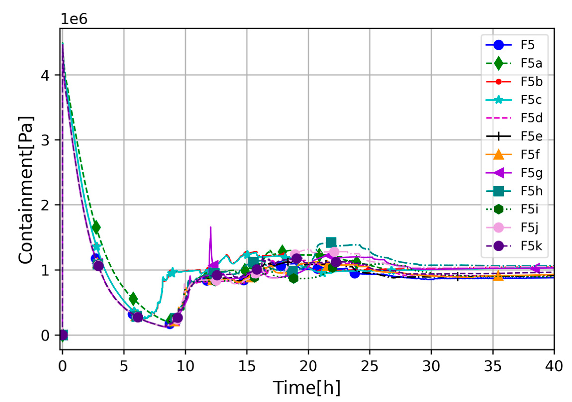
The open ventilation valve evacuates coolant from the RCS to the containment vessel, causing pressurization of the containment vessel, which reaches semi-equilibrium with the primary circuit almost immediately after initiating the event. The RCS pressure drops to about 4 MPa, which is also the maximum pressure reached by the containment vessel. From that point, the RCS and containment pressures have almost equalized, and they behave correspondingly to each other; see Figure 4 and Figure 5. Sensitivity cases F5b and F5c give slightly quicker and higher pressurization of the containment vessel between 7 and 10 h of being in the transient state. However, all cases behaved comparably to each other. The F5g showed increased pressure around 12 h, which is caused by intensive hydrogen generation at that time. One outlier occurred at around 21 h (F5h), and reached the visibly highest pressure in the post-core degradation phase. The higher pressure in the aforementioned case is related to the higher and more intense H2 generation caused by Zr oxidation. All investigated cases showed some differences in RCS and containment pressures; however, the differences are not significant, and pressure stabilized at around 1 MPa.
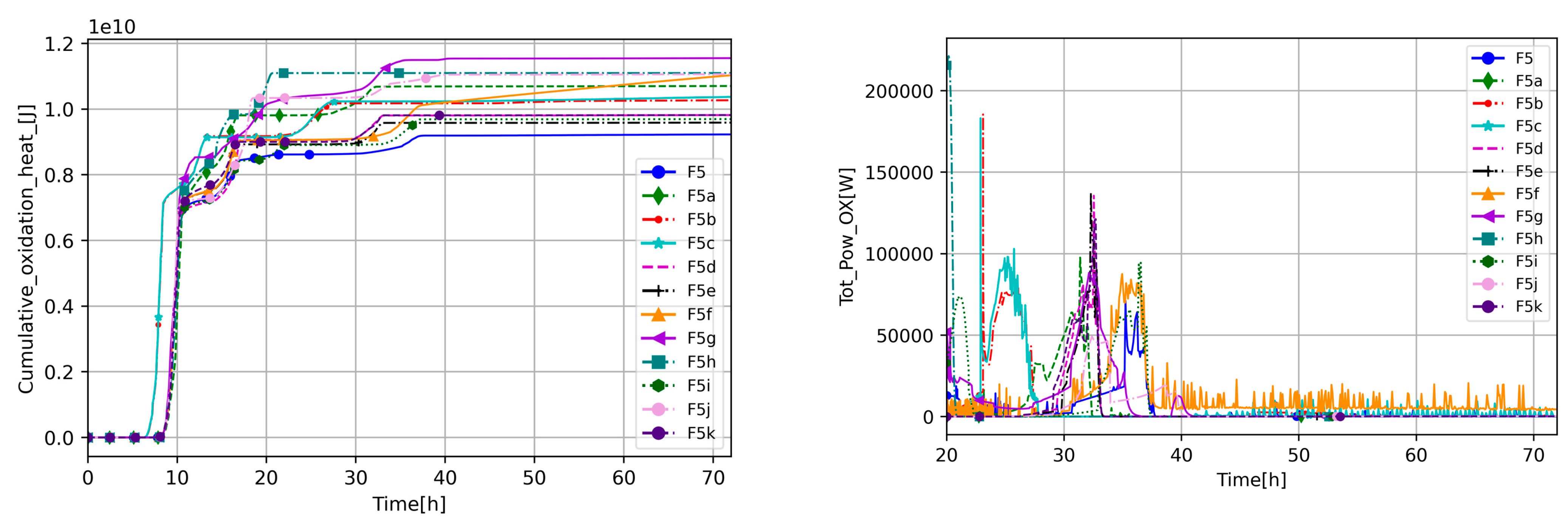
Hydrogen generation is another important indicator of accident progression and is usually directly linked with zirconium oxidation. Figure 7 presents the difference in hydrogen generation between the cases. The earliest H2 generation occurs in cases with increased decay heat, which is expected due to generally observed accident acceleration in these calculations. Analyzing the results, two main oxidation phases were distinguished. The first one started when the coolant level dropped below approximately half of the active core, which is between 6 h and 8 h of the transient state, and it is similar to all sensitivity cases. Due to the lack of effective convective heat removal by liquid water, the temperature started to increase. In this paper, it is observed that temperature escalates when the level reaches half of the core height. Also, it is common from severe accident simulations experience that temperature escalation becomes serious when water level drops to about half of the core height. The beginning and duration of the second oxidation phase varies depending on the case—see Figure 8. The second phase can be noticed by analyzing the RCS temperatures (Figure 9) and the vapor availability (Figure 10). In the case of higher decay heat, the second oxidation phase occurs at around 22 h, when the vapor mass flow rate through the RCS decreases (see Figure 10), and a peak of oxidation heat occurs (see Figure 8). For the rest of the cases where second oxidation occurs, similar behavior occurs between 30 h and 40 h. Based on H2 generation (Figure 7), it can be noticed that, in some cases (F5f), oxidation has a more continuous character than in others (e.g., F5). However, in most cases, after the first oxidation phase, the core has cooled down, and oxidation reactions slow down/stop. Nevertheless, the second oxidation phase did not cause more core degradation as the ZrO2 kept its integrity, and heat was effectively extracted.
In Figure 9, one can see the LP temperature (core inlet) and the riser temperature (core outlet); the highest temperatures are recorded in cases with high decay heat and the lowest in the cases that have increased debris porosity (F5h). The F5h case is responsible for the lowest temperature (Figure 9) as only in that case is there actual non-negligible mass circulating in the system after 35 h; see Figure 10. In all other cases, the temperature fluctuations in Figure 9 after ~35 h are related to the negligible steam mass remaining in the RCS, which low thermal inertia lets heat up and cool down rapidly, which is common for severe accident codes.
F5a, F5g, F5h, and F5j give the most rapid H2 generation (Figure 7), but it is achieved by different mechanisms. F5a, due to reduced heat transfer to the ultimate heat sink, slightly increased temperature and pressure in the system, which caused high H2 generation in the first phase and enhanced second oxidation.
The higher debris porosity, F5h, enhanced oxidization, causing higher H2 generation at the beginning of the core degradation, but, due to better cooling ability, there was no second oxidation. The F5g stands out because of the high total H2 generated, which is related to reduced debris porosity, which, by decreasing the coolability of the corium, leads to higher H2 generation (enhanced oxidation). The lower porosity, F5g, generated H2 more continuously in the first and second phases, giving similar H2 to high porosity (F5h).
The F5f, due to decreased heat transfer from the core to the bypass, presented the slowest and the most continuous H2 generations in the second oxidation phase; see Figure 8.
Figure 10 shows that steam mass flow-rate circulation in the RCS, in most cases, decreased to zero or close to zero, which is associated with oxidation; see Figure 8. This correlation indicates that the reason for reduced steam flow is that all steam in the RPV was consumed by an oxidation reaction or escaped to the containment vessel. Only the F5h case keeps a constant steam mass flow rate due to higher debris porosity and better cooling; core temperature decreased below the oxidation threshold before the whole steam was consumed.
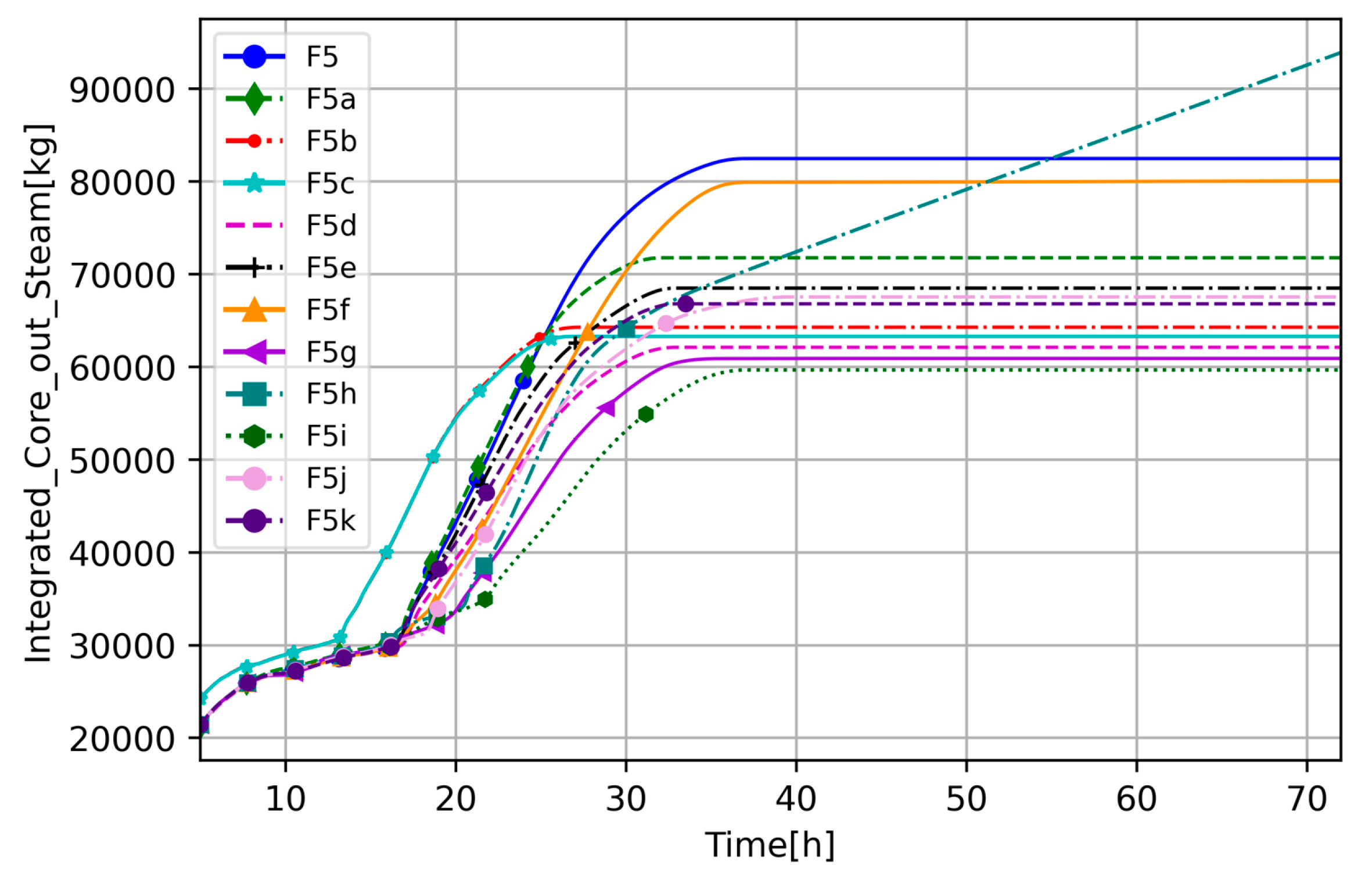
To understand transient progression and differences between the cases, the RCS circulation integrated steam and H2 mass flow is presented (Figure 11 and Figure 12). It should be noted that these figures show cumulative flow, meaning that, if it is constant, there is no flow. In Figure 11, at around 13 h the flow is higher in F5b and F5c (high decay heat) than in the other cases, which is caused by high steaming due to the core being uncovered, and it stops at around 25 h, meaning there is no more steam flow through the core. This also occurs for the other cases, but with a slight delay; extensive streaming starts at around 17 h and, depending on the cases, it stops between 30 and 35 h, which corresponds with Figure 10. While the timing when steam stops flowing is similar between the cases, the amount of steam that flew through the core is significantly different. The highest, the F5 and F5f cases, suggest that default parameters and decreased heat transfer from the core to the bypass enhance convective forces and slow the oxidation process compared to other sensitivity cases. Another outliner is the F5h case, which, as mentioned before, is the only one which did not consume steam in the oxidation; thus, integrated mass flow through the core is the highest.
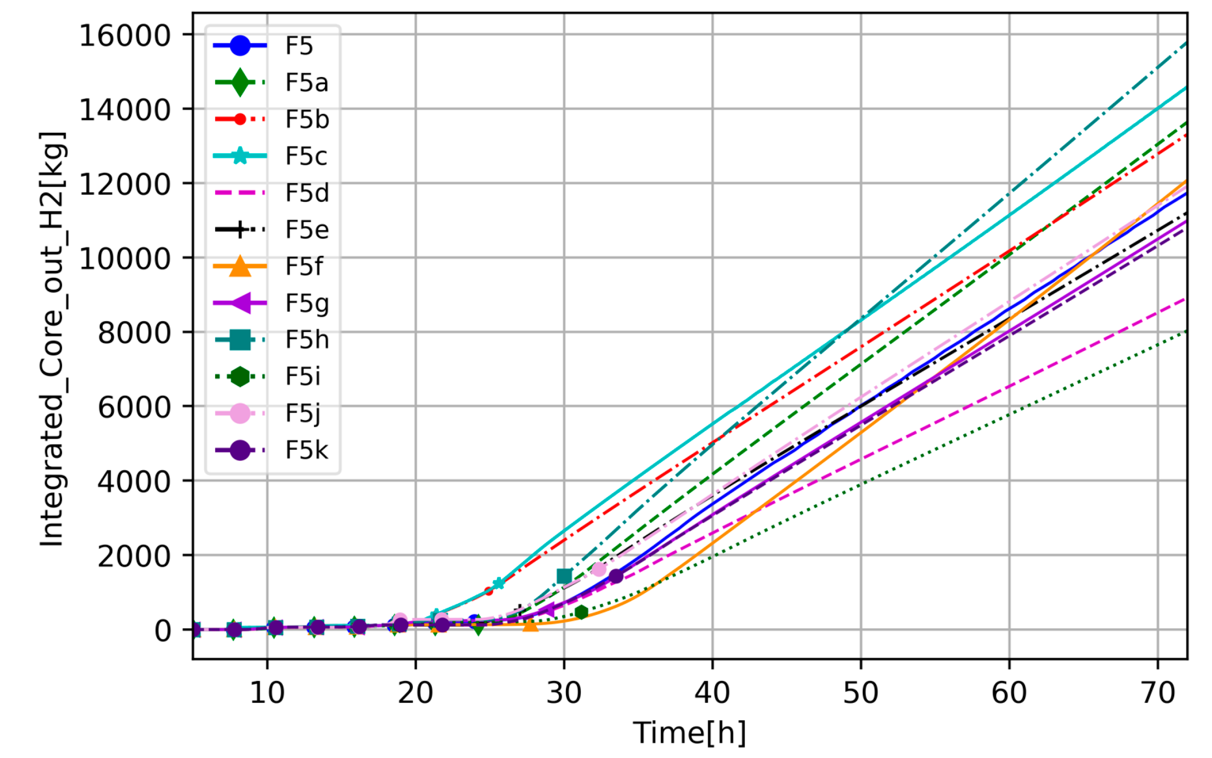
In Figure 12, the integrated H2 mass flow rate in the riser is presented. One can see that in the cases discussed above, where the steam mass flow rate drops down due to oxidation (see Figure 10 and Figure 11), the H2 is increasing, starting from the time of the second oxidation phase. In these cases, there is no steam, but H2 circulation and cooling down of the core.
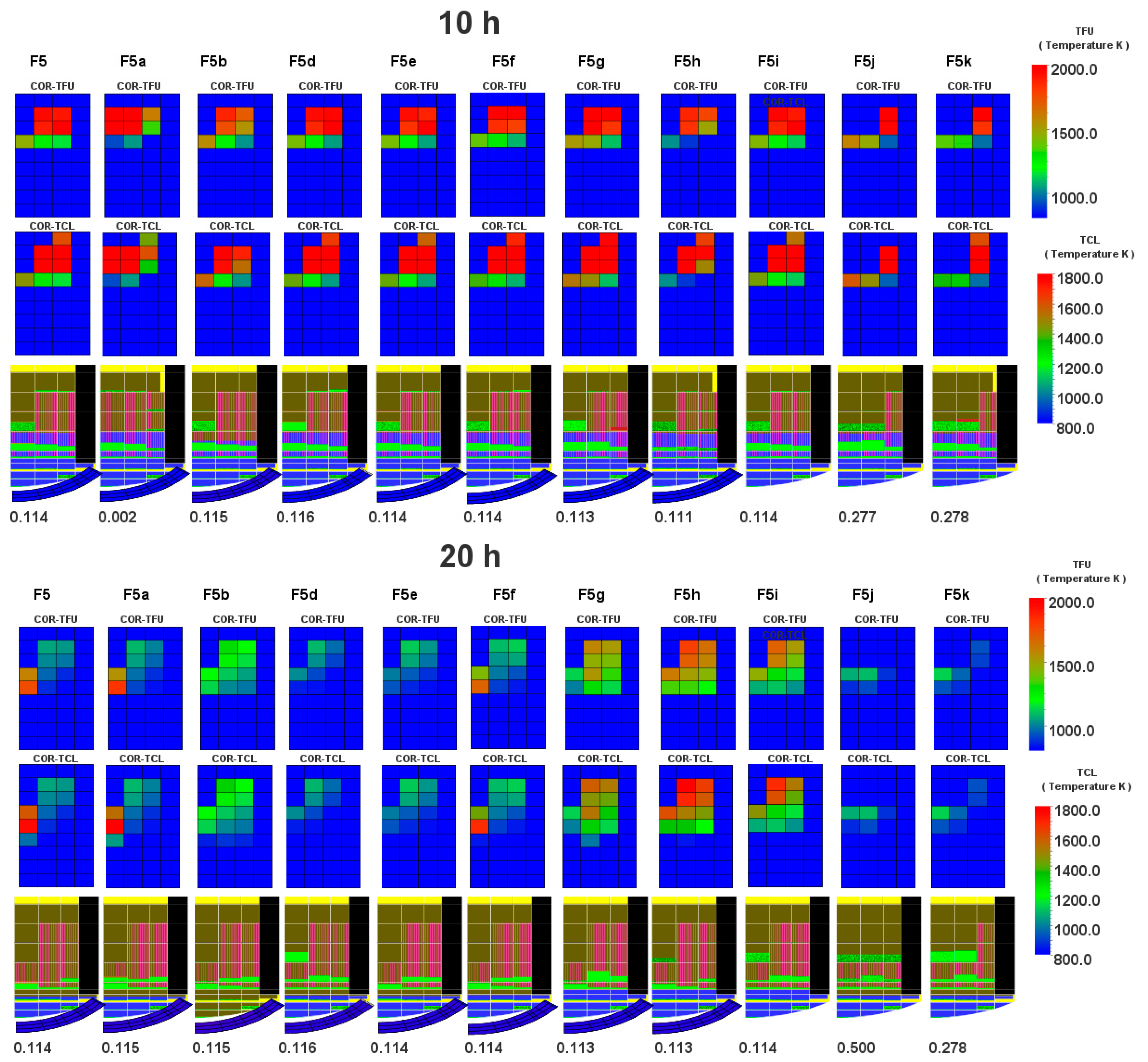
By analyzing oxidation heat (Figure 8) together with material and temperature distribution (see Figure 13 and Figure 14) (case F5c is not shown due to similarity to F5b), one can see that temperature along the core decreases with time and the highest temperature at the end of the simulation is related to the cells where core debris is collecting. Figure 13 and Figure 14 present temperature and non-zero cells, indicating which components remained uncollapsed—fuel (TFU) and cladding (TCL). The F5j and F5k cases with a modified maximum ZrO2 holdup temperature seem to affect the results the most as the core degradation is the highest in these cases. Another observation is that the F5g and F5i cases (low debris porosity and core melt breakthrough candling increased) keep a relatively high temperature in the core compared to the rest, which cools down with time. Also, there is a visible impact of high porosity (F5h), which most effectively cools down the core as a consequence of steam circulation for the whole of the transient state.
The next analyzed output parameter, which tells us about the severity of the accident, is the fraction of the degraded core (fraction of the core fuel that is no longer intact due to loss of support, liquefaction, or melting) (Figure 15). One of the goals of this study is to evaluate code sensitivity to the parameters, including potential identification of the cliff edge effects, unphysical behavior, etc. The fastest core degradation occurs in cases with increased decay heat; however, in the presented simulation, it is not responsible for the highest degradation. High decay heat, basically, does not lead to larger degradation but shifts in time over the course of events. Large degradation is caused by the collapse of outer core parts—see Figure 14. Very interesting, somehow SC-1132 helped to fail outer core regions. Analyzing the percentage of the core degradation, one can see that F5j and F5k cases showed twice as much higher core degradation (~25–50%) than others (~12%). It shows that the molten material holdup parameter is responsible for the high H2 generation as well as the containment pressurization and core degradation, which itself is not a cliff-edge effect, but it should be noted that this parameter can significantly affect the results.
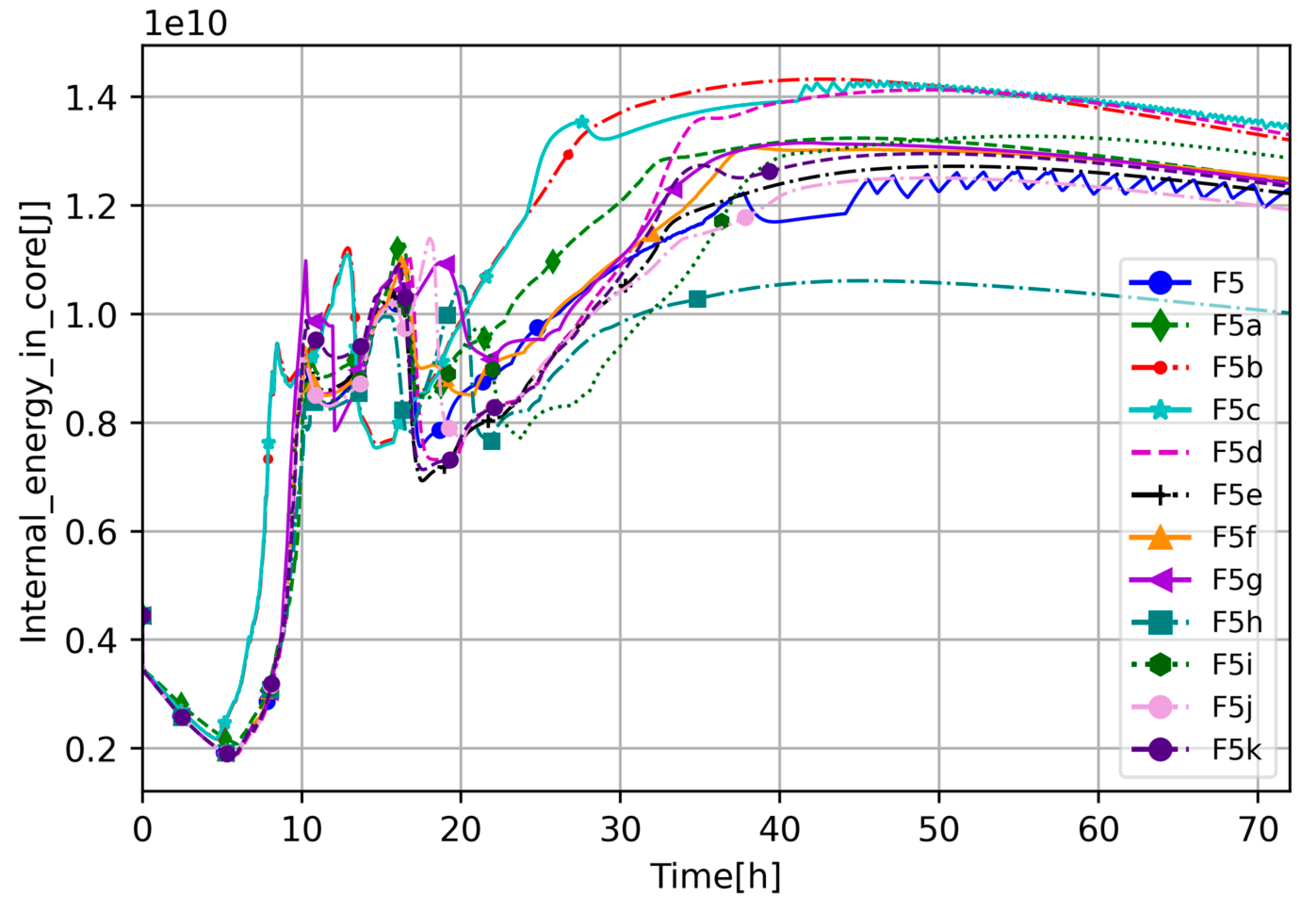
To better understand the dynamics of the investigated scenario and the impact of the selected parameters, the total cumulative energy transfer to core barrel HSs and upper core plate HSs (Figure 16) and the total internal energy in the COR package (Figure 17) were analyzed. In Figure 16, one can see that for the most crucial core degradation phase (6–20 h), the increased decay heat caused higher energy transfer to the HS at the beginning of the phase (6–10 h). The period between 10 and 20 h was full of variation between cases but in the same range, and any significant difference cannot be distinguished. However, in the scenario’s late phase, few cases provide interesting results. Besides differences linked to increased decay heat, the F5d, F5g, and F5i cases transfer more energy to the HS than the others (see Figure 16), which is a consequence of the aforementioned higher average temperature in the core and, in the case of F5d, modification of heat transfer paths. The lowest energy transfer to the HS is calculated by high debris porosity case and high molten material holdup, most probably because, in those cases, energy is transferred more efficiently to the coolant than to the HS.
In Figure 17, energy in the core is plotted. The highest energy is, as expected, related to the high decay cases; however, the F5d case, which has modified heat transfer paths from the core directly to the downcomer equalizes its core energy with higher decay heat cases. A similar but not so strong effect is shown by the F5i case, which supports the aforementioned remarks about high average core temperature and energy transfer to the HS. It shows that in the long term it could potentially increase accident consequences similarly or more than higher decay heat. This paper shows that the cases with high decay heat can shift the course of events, so the degradation happens earlier, but what is counter-intuitive is that it is not necessarily more severe in terms of core degradation—at least to some point (for 20% decay heat, for more or in a longer transient state, it is likely that it will be different). Remember that, in the studied cases, outer rings stay intact, and the value of COR-DAMAGE is driven by that. The lowest energy in the core is calculated by the case with high debris porosity as it is the one that most effectively cools down the core.
One of the goals of this study was to examine the code performance; thus, the authors decided to show differences in the CPU for CVH and COR packages (Figure 18). The parameters used for Figure 18 are COR-CPU Total CPU usage by a run portion of the COR package (units = s) and CVH-CPUC CPU usage for calculations in the RUN portion of the CVH package (units = s).
One can see that the most challenging from a computational point of view are cases F5 and F5f, which are most probably caused by flow and temperature fluctuations for F5 and continuous and slow oxidation for F5f. The cases that consume less CPU are F5b and F5g. The F5b results are surprisingly different from those for F5c, which should be similar as the modification was not significantly different between these cases. However, higher decay heat accelerates accident progression and smooths it from a computational point of view (higher temperature differences -> better convection -> fewer fluctuations). All calculations were made using a PC with Intel Core i7-8700 CPU 3.20 GHz and 16 GB RAM within a Windows environment.

5.2. Multiple Parameter Cases

The next step in this study was to develop the WCS based on the obtained results, examining if the interaction between the parameters will impact the results. The WCSs are described in Section 4.3; see Table 2. For the SC1131-2, decay heat and debris porosity were selected as potentially influential/challenging for the scenario progression and, by this, for code performance. The decay heat cases accelerate the accident progression, the SC1131-2s calculate the highest core degradation, and debris porosity could enhance H2 generation and impact core coolability.
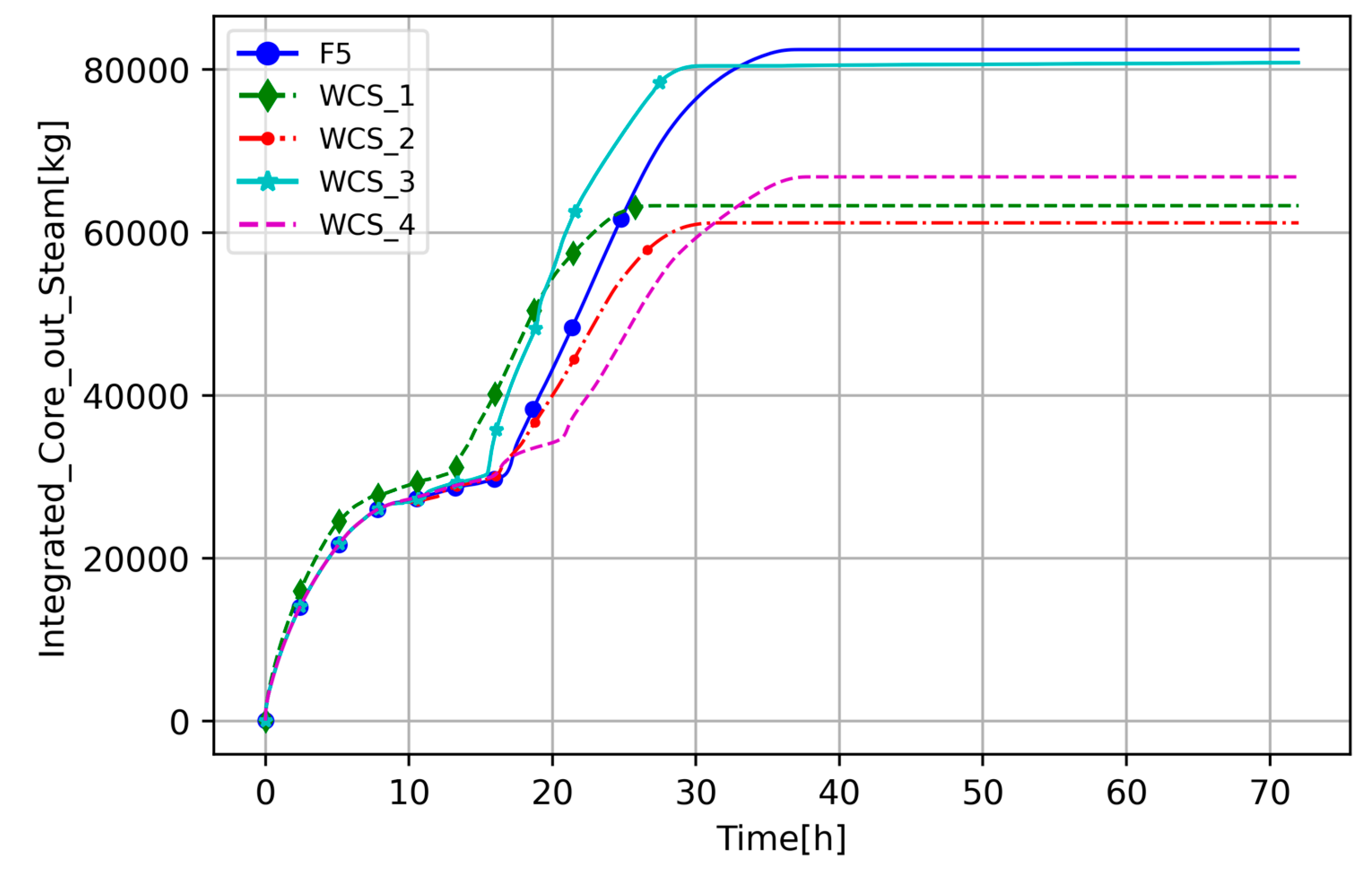
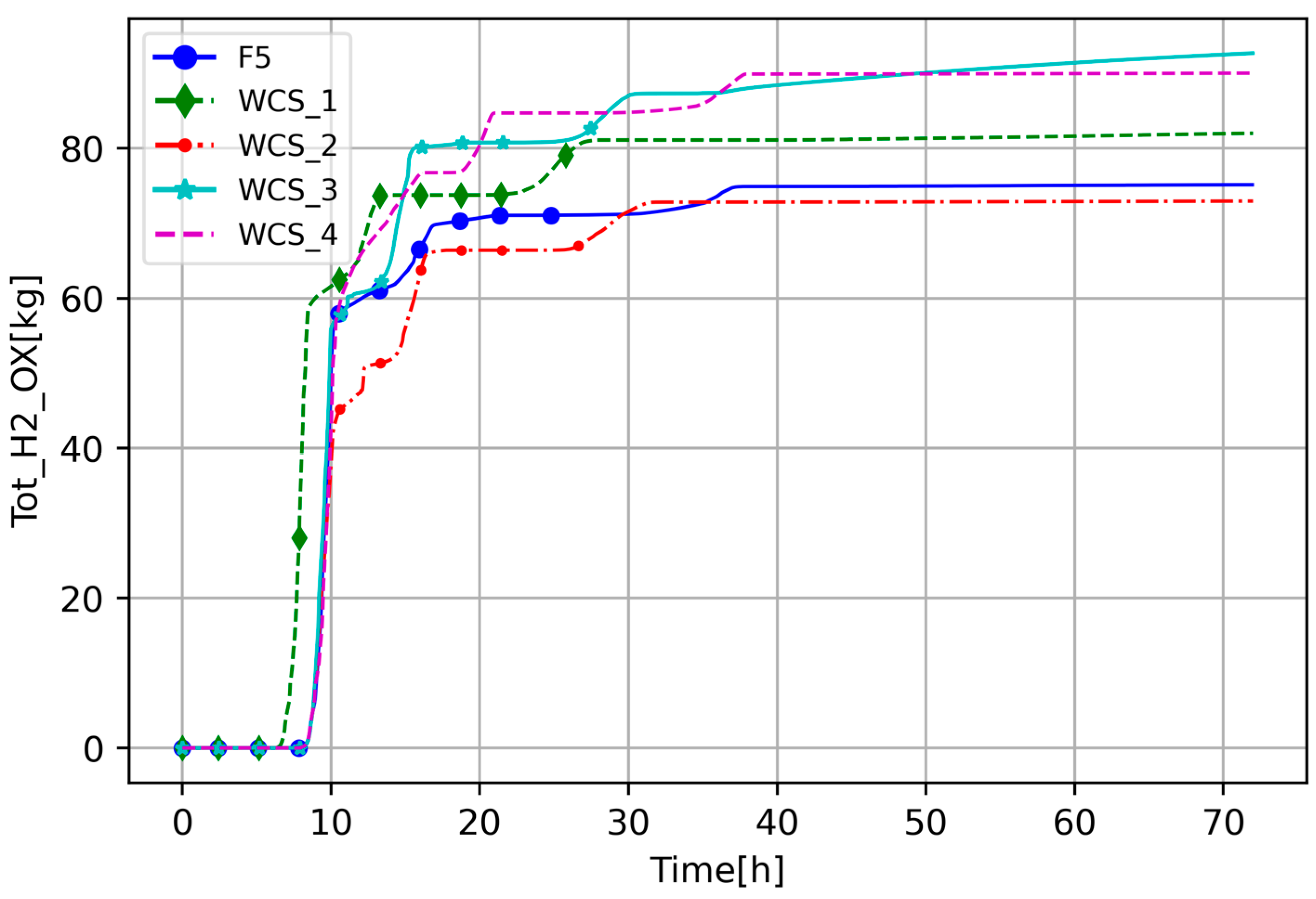
In Figure 19, the integrated mass of steam flow through the core in the WCS cases is compared with the base case F5. In the WCS_1, a combination of the most severe case (highest core degradation), F5k, with the most rapid one, F5c, (increased decay heat and lower debris porosity), did not cause more severe accident progression than the standalone increased decay heat case. One can see that the core degradation level and generated H2 (Figure 20 and Figure 21) are comparable with the case F5c. It could suggest that higher decay heat and quicker establishment of the steam’s natural circulation in the RCS are leading phenomena that could overcome the effect of modified SC1131-2 or smaller debris porosity.
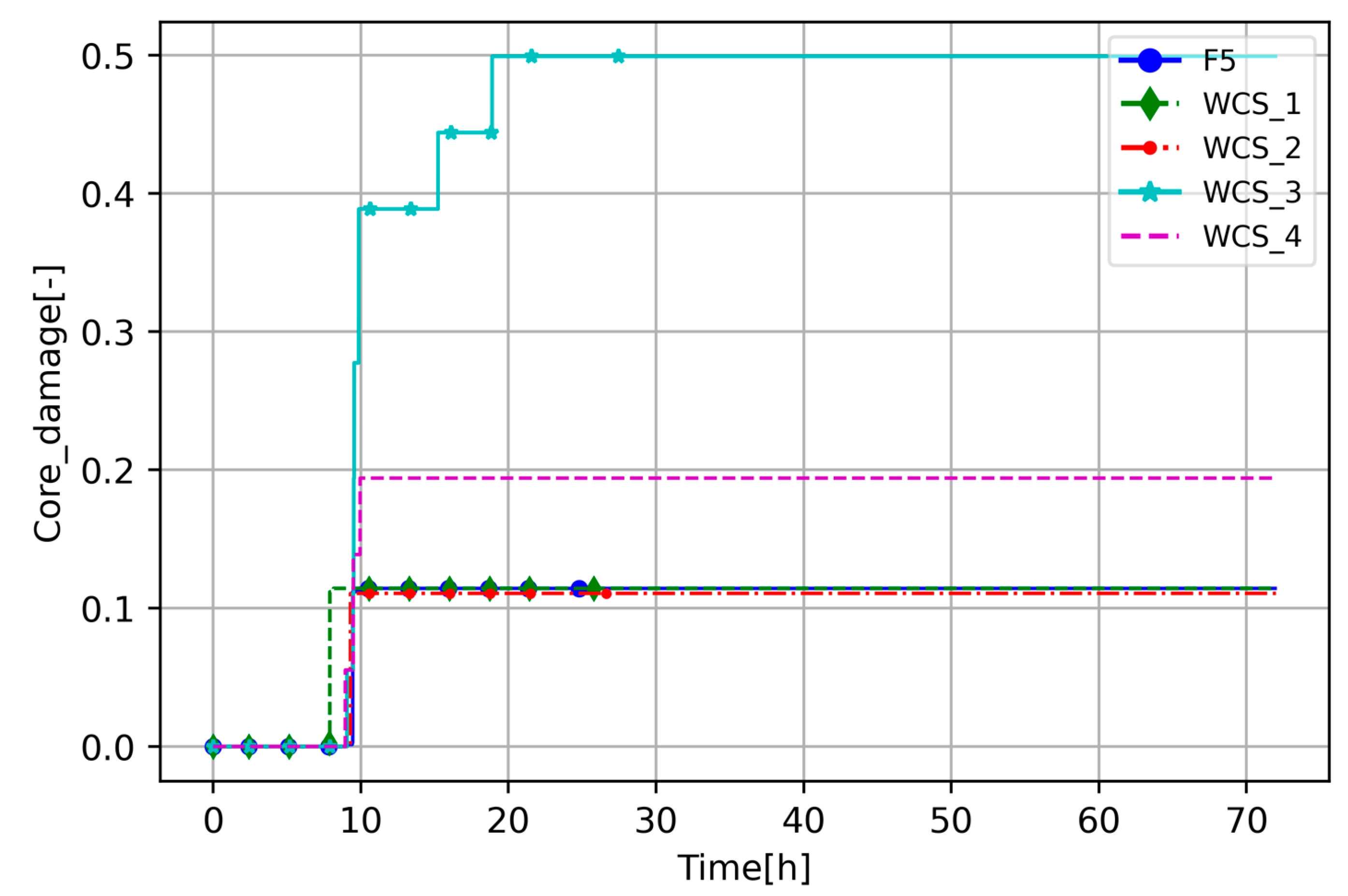
A similar configuration but without increased decay heat (WCS_2) gives, as expected, slower accident progression than WCS_1 and the same core degradation; see Figure 20. However, H2 generation in Figure 21 shows that WCS_2 produced less H2 than any other sensitivity case. The WCS_2 is a combination of F5g and F5k, which, as standalone cases, produced more H2 than when combined in WCS_2. This suggests that there might be a correlation between these two parameters.
Comparing WCS_3 and WCS_4, one can see that debris porosity can significantly affect final core degradation. Higher debris porosity (WCS_4) results in a lower steam mass flow rate (Figure 19), and lower core degradation (Figure 20), but comparable H2 generation (Figure 21). In Figure 20, one can see that decreased debris porosity did not increase core damage; however, increasing porosity can diminish the impact of the SC-1131-2 parameter, decreasing core degradation compared to standalone cases.
The overall conclusion is that analyzed factors that enhance accident severity do not add, but, in some cases, affect each other, and, based on this short comparison, one can see that leading phenomena overcome the impact of other parameters (e.g., increased decay heat and debris porosity).

6. Conclusions

This paper presents a generic iPWR MELCOR model developed for the SASPAM-SA project, and preliminary analyses of a hypothetical severe accident scenario due to postulated assumptions. The project aims to improve knowledge about iPWR modeling and SA code capabilities. The work presented in this study is focused on these topics, having as a target the MELCOR code. To examine code capability, the authors decided to simulate variants of the RVV-LOCA scenario, postulating the none operation of some safety systems. The paper’s main goal was to investigate the impact of the selected parameters on code simulation capabilities, the results obtained, and the accident’s progression. In this work, the scenario was defined and tested, and reference results were produced. The scenario was designed to be beneficial in the later stages of the WP2 of the SASPAM-SA project by identifying severe accident scenarios, due to postulated assumptions, and parameters potentially influencing core degradation. One of the goals and challenges of this work was to identify the conditions that can lead to a severe accident, i.e., significant core damage, in the examined generic iPWR design, which was achieved with the presented postulated assumptions (a spontaneous opening of the RVV, and the remaining ECCS valves being stuck closed). One base case calculation and 15 sensitivity cases were calculated and analyzed.
The results presented in the paper show that the selected parameters affect scenario progression. The increased decay heat accelerates coolant evaporation and core degradation; however, a quick water level drop allowed us to establish natural circulation of steam in the RCS (establishing steam circulation within the RCS enhances the cooling capability of the system). The vapor and H2 circulation cooled down the core and stopped its degradation. This interesting observation is similar to the spent fuel pool accident progression, in which the most crucial part of the accident is when natural circulation in the fuel racks is blocked. It shows that, in some cases, the establishment of steam circulation within the uncovered core could be beneficial for core cooling under specific conditions. However, as the presented work is a preliminary result of the iPWR PSI study in the SASPAM-SA project, the results could be burdened with uncertainty and need further investigation.
In most cases, the cladding temperature reached oxidation temperature, and the second oxidation occurred in the late phase of the accident. These cases reached the highest RCS temperatures, and oxidation consumed most of the circulating RCS vapor leading to circulation of H2 or H2-rich gas.
The highest core degradation (the largest portion of collapsed fuel) was achieved in the cases with modified molten material holdup parameter limiting values. These cases were the only ones that reached 25–50% of core degradation and showed a sensible effect on the results, as the next highest core degradation was ~12%.
As an extension of the performed sensitivities, the authors decided to merge some of the selected parameters to create “the worst-case” scenarios. One of the conclusions is that higher decay heat causing quicker reestablishment of natural circulation in the RCS is a leading phenomenon. Changing the molten material holdup parameters and debris porosity had an impact on the results, but the impact was smaller than the effect of natural circulation. The same configuration but without increased decay heat gives comparable core degradation but less H2 generation, which suggests that molten material holdup parameters and debris porosity may be correlated and impact each other as, in standalone analyses, these parameters separately generate more H2. Also, the corium porosity seemed to affect the results presented in the paper; higher corium porosity results in lower steam mass flow and core degradation but comparable H2 generation. Higher debris porosity should lead to higher steam flow; more free space should be easier for steam to reach and flow but also, it may lead to lower steam flow due to more oxidation and steam consumption (H2 generation), which confirms the complexity of severe accident phenomenology related to those challenges in numerical modeling. In that case, the impact of the porosity on the molten material holdup parameters was noticed, as higher porosity decreases core degradation.
From the CPU time-consumption analyses, it was observed that the most challenging for the code were cases in which flow and temperature fluctuations are slow, and continuous oxidation occurs. On the other hand, the cases with rapid core degradation like increased decay heat may save CPU time, which could potentially be used for further input deck optimization. As analyses in this area was not the main goal of that work, this will be investigated in further work.
The results presented here are exploratory and were performed to gain knowledge about modeling the iPWR designs and discover code limitations, given the unique design features of these reactors. Consistency with expected results and the impact of parameters on accident progression indicate that iPWR accident scenarios can be analyzed with MELCOR. The simulations show that MELCOR is able to capture the effect of the variation in the parameters, giving results consistent with the expected physics. However, a comparison with experimental data are needed to confirm that the models accurately predict the specific iPWR phenomena and identify possible uncertainty. Obtained results show that the outcome could be affected by the parametric manipulation, in some cases giving relatively high differences. Due to these discrepancies, the authors think this work should be continued as an uncertainty quantification study, which is foreseen as a next step to improve analytical knowledge about iPWRs within severe accident phenomenology.

Author Contributions

M.M.: methodology, calculations, investigation, data curation, writing—original draft, visualization, and validation. P.D.: methodology, calculations, investigation, visualization, validation, and writing—original draft, T.L.: supervision and writing—review and editing. All authors have read and agreed to the published version of the manuscript.

Funding

Funded by the European Union. Views and opinions expressed are, however, those of the author(s) only and do not necessarily reflect those of the European Union or European Commission-Euratom. Neither the European Union nor the granting authority can be held responsible for them. The grant number 101059853. Energies 17 03279 i001 This work has received funding from the Swiss State Secretariat for Education, Research, and Innovation (SERI). The grant number 22.00079. Energies 17 03279 i002 The activities of the second author, Piotr Darnowski, and his scientific visit to PSI were financed by the Mobility PW II program at Warsaw University of Technology, agreement number 1820/128/Z09/2022. Mobility PW was financed by the Republic of Poland state budget as part of the “Excellence Initiative—Research University” (IDUB) program at the Warsaw University of Technology.

Data Availability Statement

Data are contained within the article.

Conflicts of Interest

The authors declare that they have no known competing financial interests or personal relationships that could have appeared to influence the work reported in this paper.

References

  1. IAEA. Advances in Small Modular Reactor Technology Developments—A Supplement to: IAEA Advanced Reactors Information System (ARIS); International Atomic Energy Agency: Vienna, Austria, 2022. [Google Scholar]
  2. IAEA. SMR Regulators’ Forum Pilot Project Report: Considering the Application of a Graded Approach, Defence-in-Depth and Emergency Planning Zone Size for Small Modular Reactors; International Atomic Energy Agency: Vienna, Austria, 2018. [Google Scholar]
  3. European SMR Pre-Partnership Report, Workstream 5—Research, Development, and Innovation Roadmap. 2023. Available online: https://snetp.eu/wp-content/uploads/2023/07/European-SMR-pre-Partnership-WS5-report-and-roadmap-30-June-2023.pdf (accessed on 15 March 2024).
  4. Mascari, F.; Woods, B.G.; Welter, K.; D’Auria, F.; Bersano, A.; Maccari, P. Small modular reactors and insights on passive mitigation strategy modeling. Nucl. Eng. Des. 2023, 401, 112088. [Google Scholar] [CrossRef]
  5. Di Giuli, M.; Malicki, M.; Dejardin, P.; Corda, V.; Swaidan, A.M. MELCOR 2.2-ASTEC V2.2 crosswalk study reproducing SBLOCA and CSBO scenarios in a PWR1000-like reactor part I: Analysis of RCS thermal-hydraulics and in-vessel phenomena. Nucl. Eng. Des. 2022, 387, 111248. [Google Scholar] [CrossRef]
  6. Brumm, S.; Gabrielli, F.; Sanchez-Espinoza, V.; Stakhanova, A.; Nudi, M.; Groudev, P.; Ou, P.; Herranz, L.E. Uncertainty quantification for severe-accident reactor modelling: Set-up and first results of the Horizon-2020 project MUSA. Ann. Nucl. Energy 2023, 191, 109919. [Google Scholar] [CrossRef]
  7. Li, L.; Kim, T.W.; Zhang, Y.; Revankar, S.T.; Tian, W.; Su, G.H.; Qiu, S. MELCOR severe accident analysis for a natural circulation small modular reactor. Prog. Nucl. Energy 2017, 100, 197–208. [Google Scholar] [CrossRef]
  8. European Commission. Safety Analysis of SMR with PAssive Mitigation Strategies—Severe Accident—SASPAM-SA Project. 2023. Available online: https://cordis.europa.eu/project/id/101059853/de (accessed on 15 March 2024).
  9. Nuclear Regulatory Commission. MELCOR Best Practices as Applied in the State-of-the-Art Reactor Consequence Analyses (SOARCA) Project. NUREG/CR-7008; Nuclear Regulatory Commission: Washington, DC, USA, 2014. [Google Scholar]
  10. Humphries, L.L.; Beeny, B.A.; Gelbard, F.; Louie, D.L.; Phillips, J. MELCOR Computer—Code Manuals, Vol 1: User Manual; Version 2.2.14959; Sandia National Laboratories: Albuquerque, NM, USA, 2019. [Google Scholar]
  11. Xiang, Q.; Deng, J.; Du, J.; Bi, J.; Chen, B.; Li, W. Research on debris in-vessel cooling and retention behavior for the small modular reactor ACP100. Prog. Nucl. Energy 2021, 134, 103641. [Google Scholar] [CrossRef]
  12. Jiang, N.; Peng, M.; Cong, T. Flow instability analysis of natural circulation under ERVC condition for SMR. Prog. Nucl. Energy 2019, 117, 103063. [Google Scholar] [CrossRef]
  13. Maccari, P.; Mascari, F.; Ederli, S.; Meloni, P.; Manservisi, S. ASTEC code DBA analysis of a passive mitigation strategy on a generic IRIS SMR. Ann. Nucl. Energy 2021, 156, 108194. [Google Scholar] [CrossRef]
  14. IAEA. “Natural Circulation in Water Cooled Nuclear Power Plants”, Phenomena Models and Methodology for System Reliability Assessments; IAEA-TECDOC-1474; International Atomic Energy Agency: Vienna, Austria, 2005. [Google Scholar]
  15. IAEA. Assessment of Defence in Depth for Nuclear Power Plants; Safety Reports Series No. 46; International Atomic Energy Agency: Vienna, Austria, 2005. [Google Scholar]
  16. SASPAM-SA. Milestone 2.1: Generic Data on Design 1 and Design 2. 2023. Available online: https://www.saspam-sa.eu/ (accessed on 15 March 2024).
  17. Mascari, F. Safety Analysis of SMR with Passive Mitigation Strategies—Severe Accident (SASPAM-SA) Horizon Euratom Project. Etson News. September 2022. Available online: https://www.etson.eu/node/290 (accessed on 15 March 2024).
  18. Modro, S.M.; Fisher, J.E.; Weaver, K.D.; Reyes, J.N., Jr.; Groome, J.T.; Babka, P.; Carlson, T.M. Multi-Application Small Light Water Reactor Final Report; INEEL/EXT-04-01626; Idaho National Engineering and Environmental Laboratory Bechtel BWXT Idaho, LLC: Fremont, ID, USA, 2003. [Google Scholar]
  19. Mascari, F.; Vella, G.; Woods, B.G.; D’Auria, F. Analyses of the OSU-MASLWR Experimental Test Facility. Sci. Technol. Nucl. Install. 2012, 2012, 528241. [Google Scholar] [CrossRef]
  20. Humphries, L. MELCOR Code Development Status—EMUG 2017; Sandia National Laboratories: Madrid, Spain, 2017. [Google Scholar]
  21. Humphries, L. MELCOR Code Development Status—EMUG 2018; Sandia National Laboratories: Zagreb, Croatia, 2018. [Google Scholar]
  22. Humphries, L.L.; Beeny, B.A.; Gelbard, F.; Louie, D.L.; Phillips, J. MELCOR Computer—Code Manuals, Vol 2: Reference Manual; Version 2.2.14959; Sandia National Laboratories: Albuquerque, NM, USA, 2019. [Google Scholar]
  23. Lebel, L.; Morreale, A.; Batten, K.; Clouthier, T. Aerosol retention within submerged Containment-Type iPWRs: Experiments and modeling. Nucl. Eng. Des. 2022, 398, 111994. [Google Scholar] [CrossRef]
  24. Wagner, K.C.; Beeny, B.A.; Luxat, D.L.; Gelbard, F.; Louie, D.L.; Albright, L.I.; Humphries, L.L. MELCOR integrated severe accident code application to safety assessment of high-temperature gas-cooled reactors. Nucl. Eng. Des. 2023, 402, 112083. [Google Scholar] [CrossRef]
  25. Malicki, M.; Darnowski, P.; Lind, T. The iPWR MELCOR 2.2 Parametric Sensitivity Analysis. In Proceedings of the 20th International Topical Meeting on Nuclear Reactor Thermal Hydraulics (NURETH-20), Washington, DC, USA, 20–25 August 2023. [Google Scholar]
  26. Darnowski, P.; Mazgaj, P.; Włostowski, M. Uncertainty and Sensitivity Analysis of the In-Vessel Hydrogen Generation for Gen-III PWR and Phebus FPT-1 with MELCOR 2.2. Energies 2021, 14, 4884. [Google Scholar] [CrossRef]
  27. Albright, L.I.; Andrews, N.; Humphries, L.L.; Luxat, D.L.; Jevremovic, T. Material Interactions in Severe Accidents—Benchmarking the MELCOR V2.2 Eutectics Model for a BWR-3 Mark-I Station Blackout: Part II—Uncertainty Analysis. Nucl. Eng. Des. 2021, 383, 111398. [Google Scholar] [CrossRef]
  28. Darnowski, P.; Włostowski, M.; Stępień, M.; Niewiński, G. Study of the material release during PHÉBUS FPT-1 bundle phase with MELCOR 2.2. Ann. Nucl. Energy 2020, 148, 107700. [Google Scholar] [CrossRef]
  29. Gharari, R.; Kazeminejad, H.; Mataji Kojouri, N.; Hedayat, A.; Hassan Vand, M. Application of a Severe Accident Code to the Sensitivity and Uncertainty Analysis of Hydrogen Production in the WWER1000/V446. Ann. Nucl. Energy 2021, 152, 108018. [Google Scholar] [CrossRef]
  30. Galushin, S.; Kudinov, P. Analysis of the effect of MELCOR modelling parameters on in-vessel accident progression in Nordic BWR. Nucl. Eng. Des. 2019, 350, 243–258. [Google Scholar] [CrossRef]
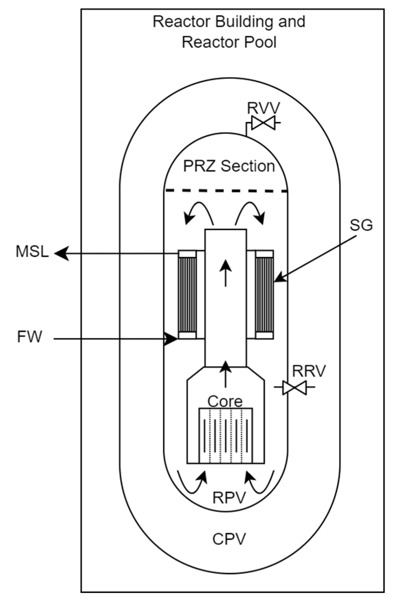
Figure 1. Basic scheme of the iPWR reactor.
Energies 17 03279 g001
Figure 2. MELCOR model of the iPWR. SNAP visualization.
Energies 17 03279 g002
Figure 3. RCS water level for the whole sequence on the left and zoom in on the right side.
Energies 17 03279 g003
Figure 4. PRZ pressure on the left and containment pressure on the right.
Energies 17 03279 g004
Figure 5. Containment pressure evolution from 0 to 40 h.
Energies 17 03279 g005
Figure 6. Reactor pool temperature.
Energies 17 03279 g006
Figure 7. Total in-vessel hydrogen generation.
Energies 17 03279 g007
Figure 8. Comparison of total oxidation heat on the left and oxidation power on the right.
Energies 17 03279 g008
Figure 9. Lower plenum vapor temperature on the left and riser vapor temperature on the right.
Energies 17 03279 g009
Figure 10. Steam mass flow rate through the riser.
Energies 17 03279 g010
Figure 11. Integrated mass flow of steam through downcomer on the left and through riser on the right.
Energies 17 03279 g011
Figure 12. Integrated mass flow of hydrogen through the downcomer.
Energies 17 03279 g012
Figure 13. Temperature distribution of fuel and cladding, and core degradation visualization at 10 h and 20 h of the transient state. Number below core visualization is COR-DAMAGE variable value at current time.
Energies 17 03279 g013
Figure 14. Temperature distribution of fuel and cladding, and core degradation visualization at 40 h and 72 h of the transient state. Number below core visualization is COR-DAMAGE variable value at current time.
Energies 17 03279 g014
Figure 15. Fraction of the core degradation (core collapse variable COR-DAMAGE).
Energies 17 03279 g015
Figure 16. Total cumulative energy transfer to HS package (units = J).
Energies 17 03279 g016
Figure 17. Total internal energy in COR package (units = J).
Energies 17 03279 g017
Figure 18. CPU time needed for COR on the left and CVH on the right.
Energies 17 03279 g018
Figure 19. The WCS integrated steam mass flow through the core comparison to the base case, F5.
Energies 17 03279 g019
Figure 20. The WCS fraction of core degradation (collapse variable COR-DAMAGE) comparison to the base case, F5.
Energies 17 03279 g020
Figure 21. The WCS H2 generation in comparison to the base case, F5.
Energies 17 03279 g021
Table 1. List of studied cases.
CaseCommentMELCOR Parameters Modifications/Field
F5Base Case—Reference case-
F5aReduced Thermal Conductivity (THC) of core barrel HS materials, RPV, and containment wall materials. Same as default stainless steel but changed table with THCIntroduced new material with properties like SS but with THC table
F5bDecay heat increased to 120%, including steady state and transientDCH_INPUT change in power
F5cDecay heat increased to 120% from the beginning of the transientDCH_INPUT with TF_INPUT table for decay heat
F5dHeat transfer directly from the COR CVHs to downcomer CVH in contrary to the base case where heat is transferred from COR to bypass and then to downcomerHS_RB, HS_RBR—Right Boundary Surface Data
HS_LB, HS_LBR—Left Boundary Surface Data
F5eModification of the HSs responsible for heat transfer from the external core to the bypass CVHAtmosphere heat transfer scaling factor ‘xhtfcr’ for external (core to bypass) side from 1.0 to 1.5
atmosphere heat transfer scaling factor ‘xhtfcl’ and ‘xhtfclr’ for internal (bypass to core) side from 1.0 to 1.5
radiative heat transfer scaling factor ‘xhtfclr’ for internal (bypass to core) side from 1.0 to 1.5
F5fModification of the HSs responsible for heat transfer from external core to the bypass CVHAtmosphere heat transfer scaling factor ‘xhtfcr’ for external (core to bypass) side from 1.0 to 0.7
Atmosphere heat transfer scaling factor ‘xhtfcl’ and ‘xhtfclr’ for internal (bypass to core) side from 1.0 to 0.7
Radiative heat transfer scaling factor ‘xhtfclr’ for internal (bypas to core) side form 1.0 to 0.7
F5gDebris porosity (PORDP) reducedPORDP from 0.4 to 0.3
F5hDebris porosity increasedPORDP from 0.4 to 0.5
F5iCore Melt Breakthrough Candling Parameters (SC1141(2))SC1141(2) from 1.0 to 2.0
F5jMolten Material Holdup Parameters
Maximum ZrO2 temperature permitted to hold up molten materials in CLading (CL) (SC1131(2))
SC1131(2) from 2400.0 to 2550.0
F5kMolten Material Holdup Parameters
Maximum ZrO2 temperature permitted to hold up molten materials in CL
SC1131(2) from 2400.0 to 2100.0
Table 2. Definition of the additional cases.
CaseMolten Material Holdup Parameter (SC-1131-2)Decay HeatDebris Porosity (PORDP)
WCS12100120%0.3
WCS22100100%0.3
WCS32550100%0.3
WCS42550100%0.5
Disclaimer/Publisher’s Note: The statements, opinions and data contained in all publications are solely those of the individual author(s) and contributor(s) and not of MDPI and/or the editor(s). MDPI and/or the editor(s) disclaim responsibility for any injury to people or property resulting from any ideas, methods, instructions or products referred to in the content.