Article

Numerical Simulation of the Transport and Sealing Law of Temporary Plugging Particles in Complex Fractures of Carbonate-Type Thermal Storage

1
School of Resources and Geosciences, China University of Mining and Technology, Xuzhou 221116, China
2
Department of Chemical and Petroleum Engineering, United Arab Emirates University, Al Ain 15551, United Arab Emirates
*
Authors to whom correspondence should be addressed.
Energies 2024, 17(13), 3283; https://doi.org/10.3390/en17133283
Submission received: 15 May 2024 / Revised: 16 June 2024 / Accepted: 27 June 2024 / Published: 4 July 2024
(This article belongs to the Special Issue Development and Utilization in Geothermal Energy)

Abstract

:
Geothermal energy plays a crucial role in the large-scale deep decarbonisation process and the transition of energy structure in our country. Due to the complex reservoir environment of geothermal energy, characterised by low porosity and permeability, conventional fracturing methods struggle to create a complex network of fractures. Temporary plugging and diverting fracturing technology (TPDF) is a key technology to improve the efficiency of geothermal reservoir extraction. However, there is still a lack of knowledge about the migration and sealing law of temporary plugging agents in complex fractures. Therefore, in this study, two multiphase flow models of temporary plugging particle transport at the fracture slit and inside the complex fracture were established by using a Computational Fluid Dynamics (CFD)-Discrete Element Method (DEM) algorithm. The influence of fracturing fluid concentration, temperature, the concentration of temporary plugging particles, and particle size combinations on migration blocking in fractures was investigated. The simulation results indicate the following: High-viscosity fracturing fluid may cause plugging particles to adhere to each other to form clusters of plugging particles, reducing dispersion during transport and slowing down the velocity of the plugging particles. A particle concentration that is too high does not have a better temporary plugging effect. The use of different combinations of particle sizes is significantly better than using a single particle size, which is a key factor for the success of fracture plugging. The research findings are of great theoretical and practical significance for scaled-up, vibration-controlled fracturing technology in geothermal reservoirs.

1. Introduction

Nowadays, the world energy crisis and environmental problems are getting more and more serious, and hot dry rock (HDR) has become a new type of clean energy that countries around the world are focusing on researching and developing due to its extreme cleanliness, stability of operation, and wide spatial distribution [1,2,3]. Nevertheless, due to the low porosity and low permeability of HDR, the direct extraction of thermal energy is not an easy task, and it is usually necessary to form an enhanced geothermal system (EGS) through hydraulic fracturing techniques [4,5,6]. However, hot dry rock is generally deeply buried and has higher geostress anisotropy and stratum inhomogeneity. Relying on conventional fracturing methods can generally only form a relatively single fracture, and it is difficult to form a complex fracture network. In the process of extraction, there is a phenomenon whereby fracturing fluid preferentially flows into the larger fracture and the high permeability layer section with less resistance, the smaller fracture section or low permeability layer in the stratum cannot be improved, and the injection of water for heat extraction is prone to rapid thermal breakthrough, leading to the low efficiency of heat extraction. To address these problems, the use of TPDF has been proposed in recent years to improve these situations [7,8].
TPDF technology seals the first-pressure fracture by pumping a degradable temporary plugging agent, changes the direction of fluid flow, and opens a new fracture in the unmodified or under-modified layer section, which dramatically improves the overall modification effect. In this process, providing temporary plugging particles to the proper area of the fracture is critical for fracture sealing [9,10,11,12]. In the past few years, many large-scale experiments on TPDF have been reported in the literature [13,14,15]. Yang [13] used natural rock samples to conduct multi-branching seam temporary plugging and fracturing experiments to study the effects of horizontal principal stress difference, closure stress, displacement, natural fractures, and other factors on the branching seam expansion pattern. Li et al. [14] conducted experiments to study the mechanism and sealing efficiency of the fibre and particle temporary plugging technology. Based on a consideration of fracture morphology, he investigated the optimal ratio of a temporary plugging agent for different fracture widths and analysed the temporary plugging mechanism by combining it with CT scanning technology. Zhang et al. [15] conducted large-size true triaxial temporary plugging fracturing simulation experiments to investigate the temporary plugging mechanism and fracture extension behaviour and explored the influence of the temporary plugging agent dosage. Li et al. [16] conducted indoor multi-cluster temporary plugging fracturing experiments in horizontal shale wells; investigated in detail the effects of fracture spacing, the number of fractures, ground stress, and the type of injected fluids on the initiation of multi-cluster fractures; and quantitatively investigated the expansion pattern of multi-cluster fractures during the TPDF process. Li et al. [17] proposed a new method of multi-stage and multi-cluster temporary plugging experiments in horizontal wells that considered fracture temporary plugging and segmented temporary plugging and investigated the effects of the particle size combinations of the plugging agent, its concentration, and the number of clusters at a certain stage on the geometry of fractures. Chen et al. [18] developed a new thermo-responsive temporary plugging agent by conducting indoor tests that were successfully applied in the field, and the production and injection data in the field proved that the effect of production increase was remarkable. In addition, many other scholars have verified the advantages of temporary plugging fracturing in the field [19,20,21]. Nevertheless, accurately depicting the migration process of particles within the fracture during experiments remains challenging due to the inability to directly observe this process. Hence, there is a pressing need for numerical simulation studies to elucidate the transport dynamics of temporary plugging particles within hot storage fractures.
Shahri et al. [22] initially discussed the inflow mechanism into an existing flow path using numerical simulation methods. In recent years, several scholars have employed the coupling of CFD-DEM to model particle transport in fractures [23,24,25]. The CFD-DEM coupling methods are mainly Eulerian–Eulerian and Eulerian–Lagrangian models. The Eulerian–Eulerian method treats the particle phase as a pseudo-fluid state, occupying the fluid space together with the original fluid, which is regarded as a continuous medium. Gong et al. [26] used this method to establish a two-phase flow model for the transport of particles in a complex fracture network, considering the fracture surface roughness, and found that the fracture surface roughness can significantly slow down the transport of particles. Han et al. [27] used the Eulerian–Eulerian particle model to simulate the transport of particles in fractures, investigated the particle transport process under different fracture geometries, and explored the effects of key parameters such as fracturing fluid viscosity, particle concentration, and injection rate on the transport process. The Eulerian–Lagrangian model, on the other hand, treats the solid particles as discrete phases and calculates the equations of motion of the particles during the simulation to obtain their trajectories, which can more accurately simulate the migration process of the particles. Wu et al. [28] used this method to establish particle transport efficiency under controlled flow conditions. Lan et al. [29] established a two-phase flow coupling model, considering the adhesive contact force of the coated particles; investigated the cementation characteristics of the coated particles in the conveying process; and divided the transport process of the coated particles into four phases in the cracks by the dynamic change of the generating pillars of the coated particles, which revealed the mechanism of the conveyance of the coated particles. Sui et al. [30] systematically explored the transport and deposition of transient plugging particles of varying sizes and size ratios in vertical wellbores, horizontal wellbores, and fracture sites. They also optimised operational parameters for temporary plugging and fracturing in practical scenarios. Wang et al. [31] investigated the migration and deposition process of a temporary plugging agent in HDR based on the CFD-DEM method and investigated the influencing factors of temperature, friction between particles, etc. Zheng et al. [32] assessed the actual fracture sealing capability of HDR using computed tomography (CT) scans and a physical model of real fractures, examining the impact of variables like wall temperature, fracture roughness, injection angle, and position on temporary plugging agent on transport in rough fractures. While the aforementioned studies focused on granite, research on the migration of temporary plugging particles in the thermal storage of carbonate rocks remains limited.
Following comprehensive information from the literature, this study adopted a two-way coupled CFD-DEM computational method to simulate the transport and sealing process of temporary plugging particles in complex fractures in carbonatite-type thermal reservoirs. Through this coupling algorithm, relevant information such as the velocity and number of temporary plugging particles in the fracture during their migration in the fracture could be accurately captured. In addition, the influence of fracturing fluid concentration, temperature, the concentration of temporary plugging particles, and particle size combinations on the transport process of a temporary plugging agent in fractures was also analysed. The findings of this research are of great theoretical and practical significance for scaled-up, vibration-controlled fracturing technology in geothermal reservoirs.

2. Mathematical Model

2.1. Basic Assumption

Because CFD-DEM involves a high number of calculations, the model’s parameters needed to be simplified in the numerical simulation to save time and money without sacrificing generality.
(1) It was assumed that the fluid in the fracture was an incompressible Newtonian fluid and the inhomogeneity of the matrix was not considered.
(2) It was assumed that the temporary blocking agent particles were spherical. The basic properties of the particles, such as particle size and density, remained unchanged during the simulation.
(3) Fluid motion satisfied Darcy’s law.
(4) Heat transmission satisfied Fourier’s law of thermal conductivity and local thermal equilibrium.

2.2. Governing Equation of Fluid

Fluid flow within the fracture followed the flow dynamics, continuity equation, and Navier–Stokes equation used to control the incompressible fluid flow fraction of the unit cell to calculate the continuous phase process [33]. While fluid flow in a porous matrix is described by Darcy’s equation, its storage effect occurs during the flow in the matrix due to the compressibility of the fluid and the pores, and the controlling equations of the fluid in the matrix are as follows:
t ( ρ 1 ϕ ) = ρ 1 S p ml t
S = ϕ K f + α B ϕ K s
ρ 1 [ K μ ( p ml + ρ 1 g H ) ] + ρ 1 S p ml t = ρ 1 α B ε wl t
In this formula, K (m2) is the permeability in the rock matrix, ρ 1 (N) is the pressure, p ml (kg/m3) is the water density, g (m/s2) is the gravitational acceleration, ϕ is the porosity, and ε wl t is the rate of change of the volumetric strain in the matrix.

2.3. Governing Equation of Particle

The flow of temporary plugging particles in the fracturing fluid belonged to a solid–liquid two-phase flow, which received exogenous force from the external flow field on the particles and endogenous force from the collision of the particles with each other in the process of transport. This study made use of Newton’s second law to calculate the particles. The fracturing fluid flowed into the fracture and also seeped into the matrix, which made the velocity gradient along the fracture direction much larger than that perpendicular to the fracture direction, so the effect of the Saffman force on the particles could be neglected.
m p d u p d t = F i + F g + F d + F p g + F s + F b + F v m
I p d ω p d t = T p
In this formula, F i (N) is the collision force between the particles, F g (N) is the mass force on the particles, m p (kg) is the mass of the particles, u p (m/s) is the velocity of the particle motion, F d (N) is the fluid trailing force on the particles, F p g (N) is the pressure gradient force, F v m (N) is the virtual mass force, F b (N) is the Bassett’s force, T p (N m) is the collision moment of the particles, I p (kg m2) is the moment of inertia of the particles, and ω p (rad/s) is the angular velocity of particle motion.
The fluid resistance to the particles was as follows:
F d = 1 8 C d π ρ f D p 2 u f u p ( u f u p )
In this formula, C d is the coefficient of drag force, D p (m) is the particle diameter, and u f (Pa·s) is the apparent viscosity of the fluid. In this study, the temporary plugging particles were regarded as regular spherical particles. Then, its trailing force coefficient could be obtained from the particle Reynolds number.
R e p = ρ 1 d p | u 1 u p | μ
C d = { 24 R e p ( 1 + 0.15 R e p 0.687 ) , R e p 1000 0.44 , R e p > 1000 }
The equation for the pressure gradient force was as follows:
F p g = π d 3 p 6   p fl l

2.4. Governing Equation of Heat Transfer

For a fluid flowing in a fracture, there are two modes of heat transfer: heat conduction and heat convection. In this study, we mainly considered the heat conduction mode, which satisfied Fourier’s law of thermal conductivity, since the bedrock skeleton and the fluid existed simultaneously. However, the thermophysical parameters of the two are inconsistent, so it is generally necessary to establish the energy conservation equations for bedrock and fluid separately [34]:
( ϕ ) ( ρ C p ) s T t = ( 1 ϕ ) ( λ s T ) + ( 1 ϕ ) Q s
ϕ ( ρ C p ) l T t + ( ρ C p ) l ( V l T ) = ϕ ( λ 1 T ) + ϕ Q l
In this formula, ( ρ C p ) s is the heat capacity of the rock skeleton, J/(m3‧K); λ s is the heat conduction tensor of the rock skeleton, W/(m‧K); Q s is the heat source strength of the rock mass, W/m3; ϕ is the rock porosity, dimensionless; ( ρ C p ) 1 is the heat capacity of the fluid, J/(m3‧K); λ l is the heat conduction tensor of the fluid, W/(m‧K); Q l is the heat source strength of the fluid, W/m3; and v l is the Darcy velocity of the fluid, m/s.
For the single-phase flow problem, after superposing Formulas (10) and (11) and considering the deformation energy, Formula (12), when local thermal equilibrium was satisfied, the bedrock temperature field control equation was obtained as follows:
( ρ C p ) m T t + ( T 0 + T ) K α T ε ν t + ( ρ C p ) l ( V l T ) = ( λ m T ) + Q T
In this formula, T 0 is the temperature without stress, K; ( ρ C p ) m is the average heat capacity of the porous medium, J/(m3‧K); λ m is the average heat transfer coefficient of the porous medium, W/(m‧K); and Q t is the heat source of the porous medium, W/m3.

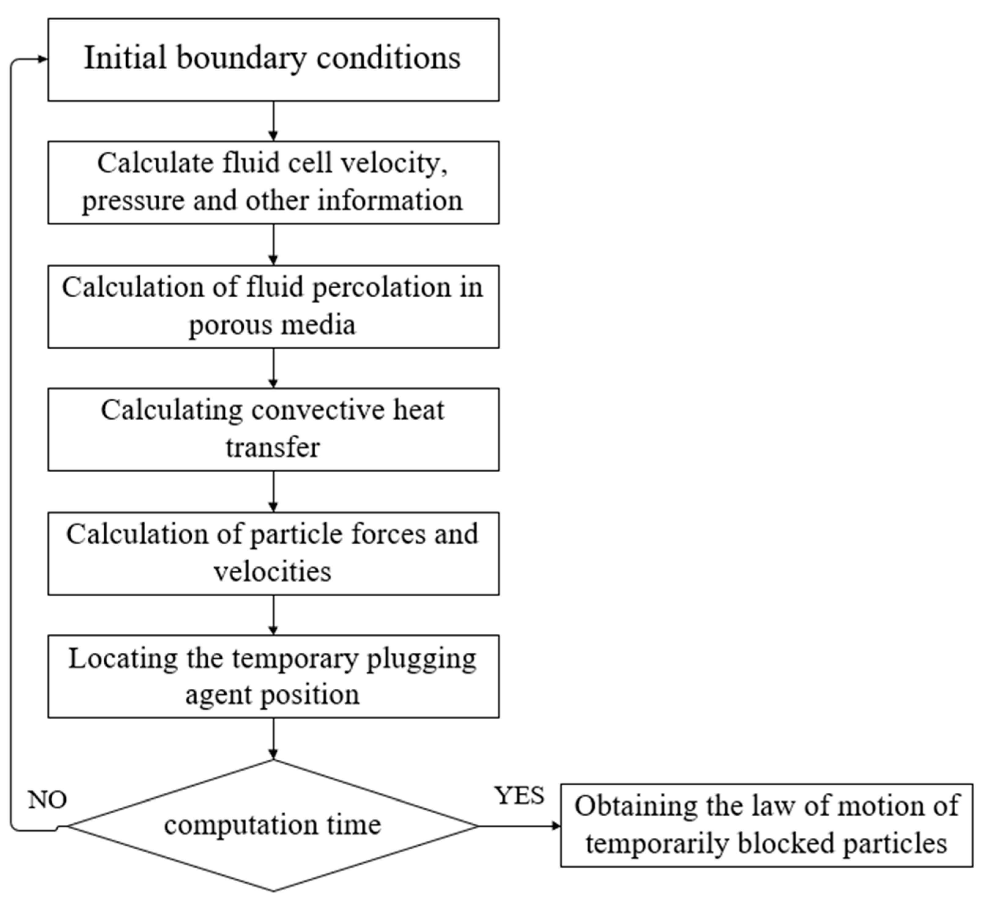
2.5. CFD-DEM Coupling Calculation

According to the model flowchart (Figure 1), we divided the simulation process into two main parts: (1) fluid flow within the fracture and the effect of temperature on the fluid and (2) the two-way coupling effect between the fluid and the temporary plugging particles. In the first part, we applied the PARDISO algorithm to perform fully coupled calculations of the fluid and heat transfer variables, taking into account the fluid flow in a porous medium. In the second part, we used the fluid velocity, pressure, and computational step size data obtained from the first part of the calculations to perform iterative calculations with the GMRES solver in order to obtain information about the particle granule sub-release and its trajectory in the fracture.

3. Construction of Numerical Model

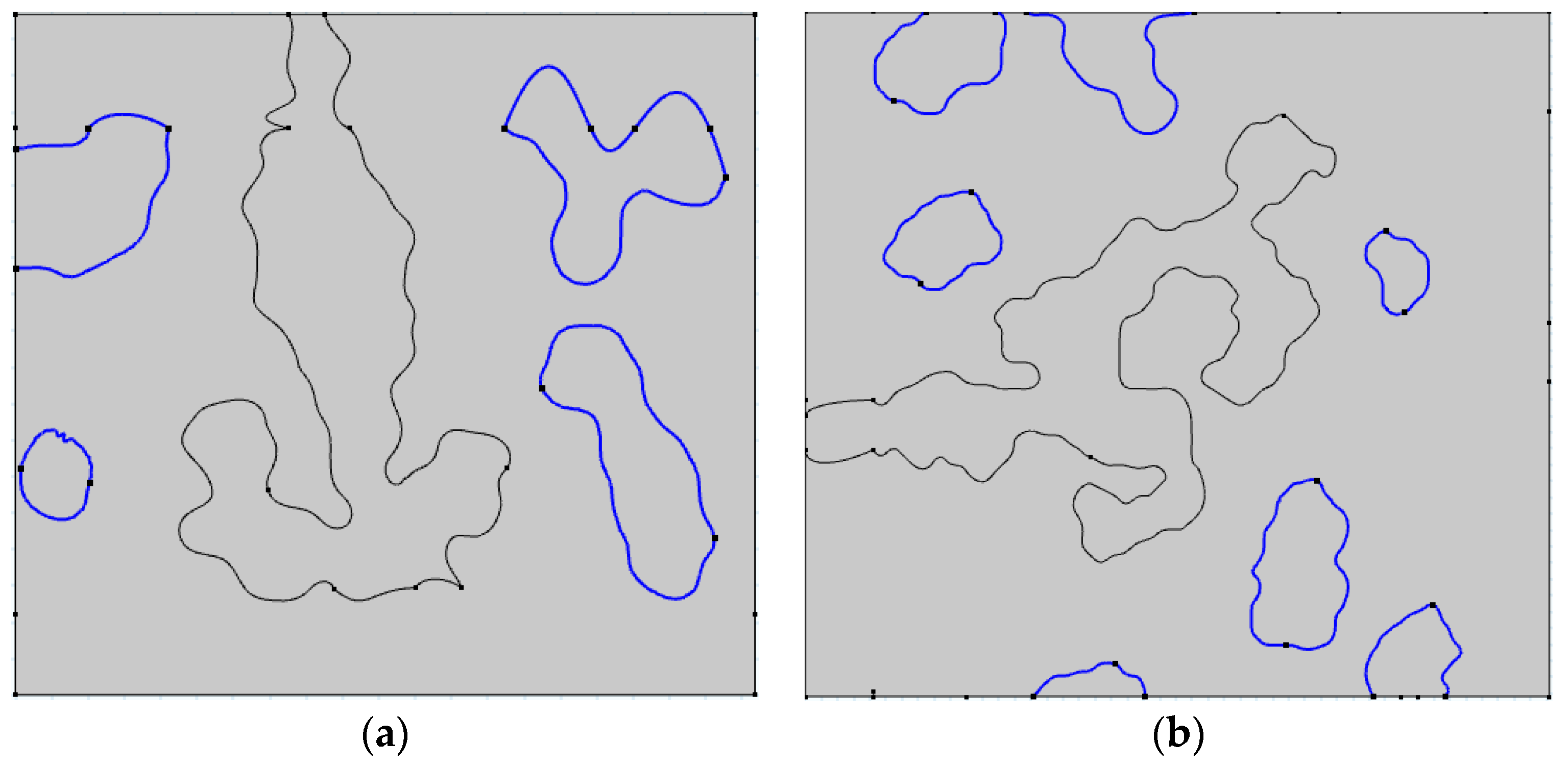
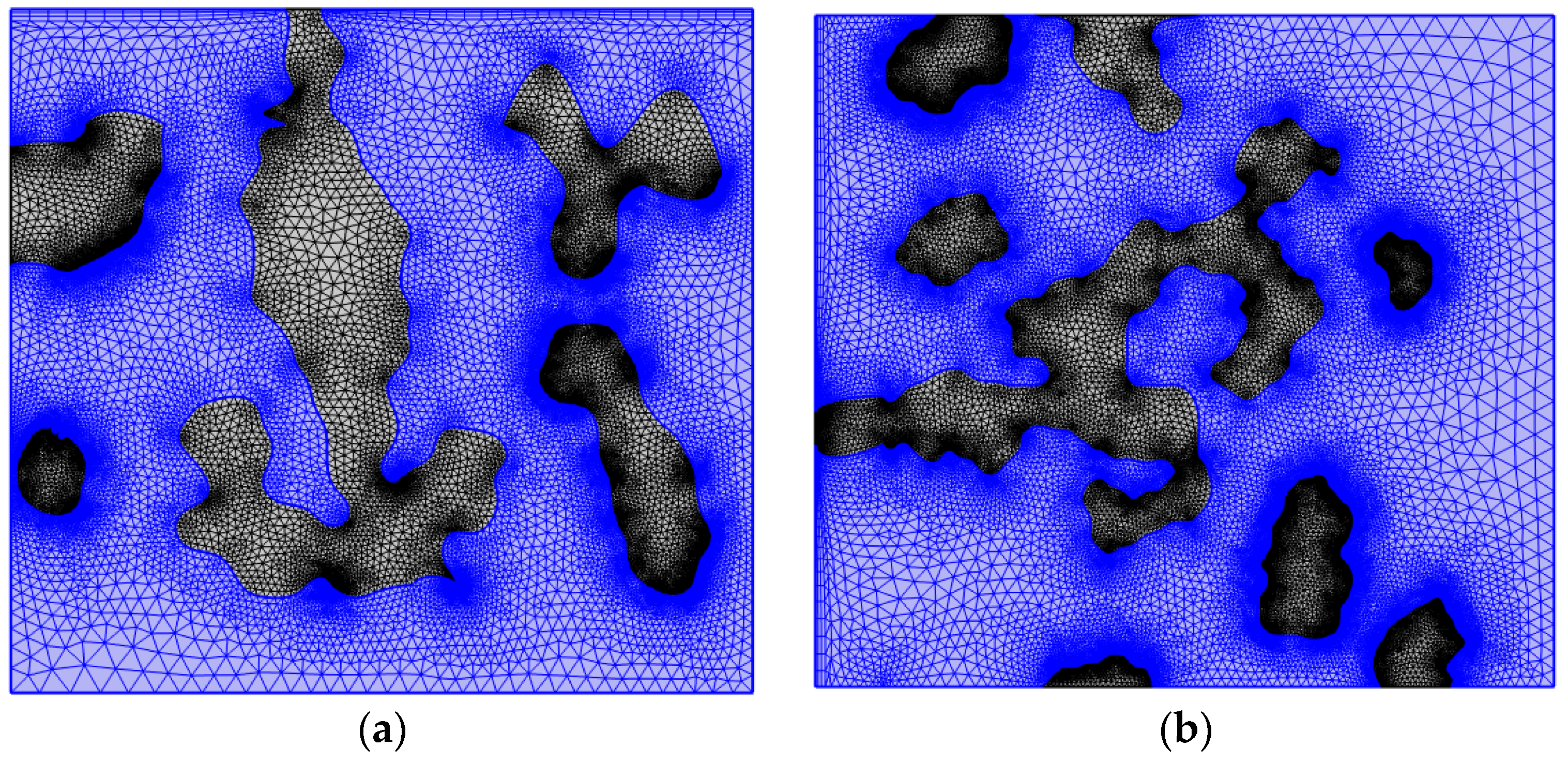
3.1. Construction of Numerical Model

For the construction of complex fractures in thermal reservoirs, scholars have constructed simple models of a single long fracture, tortuous fracture, or rectangular or cylindrical body for simulation, and most of them are of granite-type thermal reservoirs; there are fewer models of carbonate-type thermal reservoirs with fractures. However, the fracture situation of carbonate reservoirs is complex and diverse, not only with artificial fractures but also with magnanimous microfractures, holes, natural fractures, and other weak structural surfaces. In order to realistically restore the transport of temporary plugging particles in the internal rock layer of carbonate thermal storage, we adopted the Quartet Structure Generation Set (QSGS) method to simulate the random phase distribution characteristics of the porous medium and construct a structural model of the porous medium with complex fractures.
The QSGS method is able to generate porous media with a real microstructure, based on which, two fracture models of 10 cm × 10 cm in size were built in this study, as shown in Figure 2. The blue line area in the figure indicates the constructed natural fractures such as tiny fractures and holes and the grey area indicates the porous medium area inside the rock. According to the structural characteristics of the simulated thermal storage, a free triangular mesh was used for mesh generation, with a total of 26,649 unit counts for the fracture slit plugging model and 45,031 unit counts for the complex fracture temporary plugging model (Figure 3).

3.2. Initial and Boundary Conditions

The carbonate reservoir in the North Jiangsu Basin was selected as the research object, the field samples were collected, and physical and mechanical properties were tested. A numerical model was established from these data, and the specific parameters are listed in Table 1. The upper, lower, and right boundaries of the simulation area were set as “open boundaries” and given a certain pressure so the fluid could flow out of the wall. The particles were randomly injected from the inlet and continued to be injected over time.

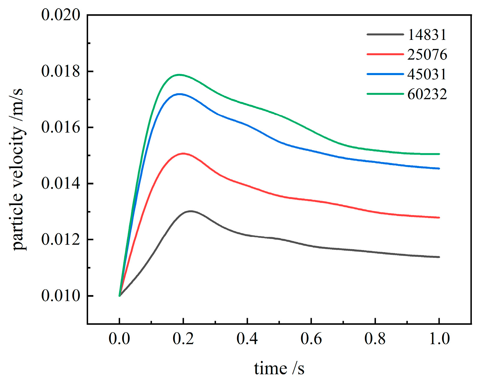
3.3. Grid Independence Verification

When performing numerical simulations, the number of meshes divided affects the simulation results. When the number of grids is small, there is a large error, which is very different from the actual project. Excessive refinement is very demanding on the performance of the computer, and when the refinement is to a certain extent, the improvement of the solution accuracy is no longer significant. Therefore, based on the project requirements, a reasonable choice of meshing strategy needed to be made. To predict particle transport during the temporary filling of complicated fractures, four discrete computational region models with varying grid nodes (14,831, 25,076, 45,031, and 60,232) were created. These independent modules were briefly inserted under identical settings. Figure 4 depicts the results of particle velocity comparisons using four discrete models. The comparison results show that the error was within the acceptable range of 5% for calculations using 45,031 grids and 60,232 grids. However, for those using 25,076 grids, the results were quite different. Therefore, to increase the computational speed of the model while ensuring computational accuracy, 45,031 grids were used for future computations.

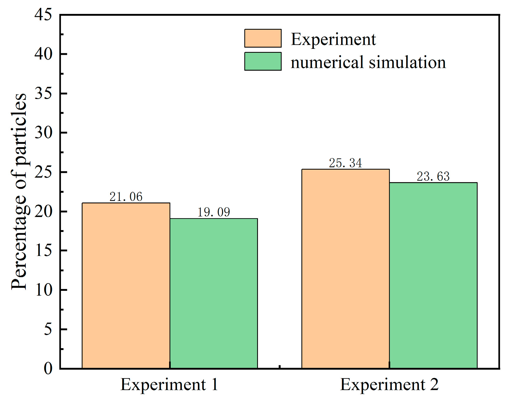
3.4. Model Validation

In order to verify the accuracy of the mathematical model proposed in this paper in the temporary plugging and fracturing process, it was necessary to first ensure that the reliability of the model was effectively demonstrated, so the numerical simulation results were compared with the existing experimental data in Li [35]. In the literature on the distribution characteristics of particles, three intervals were set up, and the effect of different engineering parameters on particle transport was investigated; this paper selected one of the intervals for validation, and the results are shown in Figure 5. The error of numerical simulation was within the acceptable range, so it can be considered that the model and numerical simulation method established in this study were in line with the experimental law and could meet the subsequent research requirements for the transport law of temporarily blocked particles under different parameters.

4. Results and Discussion

Based on the above numerical model, we studied the temporary blockage of particle transport in two scenarios, namely, the location of a crack opening in the early stage of hydraulic fracturing and the formation of complex fractures inside a rock after hydraulic fracturing. We aimed to understand the transport processes of different temporary blockage methods in order to determine the optimal transport conditions. For this purpose, we analysed the sensitivity of the operating and performance parameters of the temporary plugging agent.

4.1. Particle Migration and Plugging Simulation

Once the particles entered the fracture alongside the fracturing fluid, their transport mechanism became intricate and varied as a result of the combined effects of the fluid’s horizontal carrying force, vertical buoyancy, the trailing force of the particles, gravity, and the elevated temperature of the rock. At first, the fracturing fluid flowed inside the fracture, but, at the same time, it leached into the matrix, and the amount of leaching gradually decreased from the inlet to the depth of the fracture. The flow of the fracturing fluid through the fracture is shown in Figure 6, where the white line is the flow line of the fluid. Since the matrix was surrounded by a constant pressure boundary, the pressure gradient on the side of the fracture near the boundary was larger, which made the fracturing fluid filtration loss more obvious.
The trajectory of temporary plugging particles is shown in Figure 7 and Figure 8. In the pre-simulation period, the fracturing fluid carried the particles in the stratum, and when it reached the fracture area, it preferentially flowed into the larger or longer fractures to be precipitated and seal the fractures. In this simulation, the effectiveness of the sealing was evaluated by counting the number of particles that reached the cracks that needed to be temporarily sealed.

4.2. Simulation of Temporary Plugging of Fracture Slit

4.2.1. Effects of Different Injected Displacements

The injection displacement of fracturing directly affected the delivery rate of temporary plugging particles and the effect of fracture plugging, and the influence of the injection displacement was investigated by analysing the trajectory and velocity of the particles in this simulation process. Due to the filtration loss of the fracturing fluid, the flow rate of the fracturing fluid in the fracture showed a decreasing trend in general, and the decreasing rate of the fracturing fluid in the fracture increased with the increase in flow rate. As shown in Figure 9, there was a significant velocity threshold for the fracturing fluid velocity to stabilise the fluid decline rate.
Figure 10 shows the trajectory of the particles under different injection discharges at the same time. It was found that when the injection discharge was low, the particles did not reach the fractures due to the small fluid velocity, and the temporary plugging effect was not achieved, but, when the injection discharge reached a certain value, the temporary plugging particles reached the fractures due to the larger velocity, and the rebound force at the wall of the fracture not only made the particles migrate to the large fractures but also migrated to the small fractures, resulting in both sides being blocked, and the plugging effect was not achieved. Migration led to both sides of the plugging not achieving a proper plugging effect.

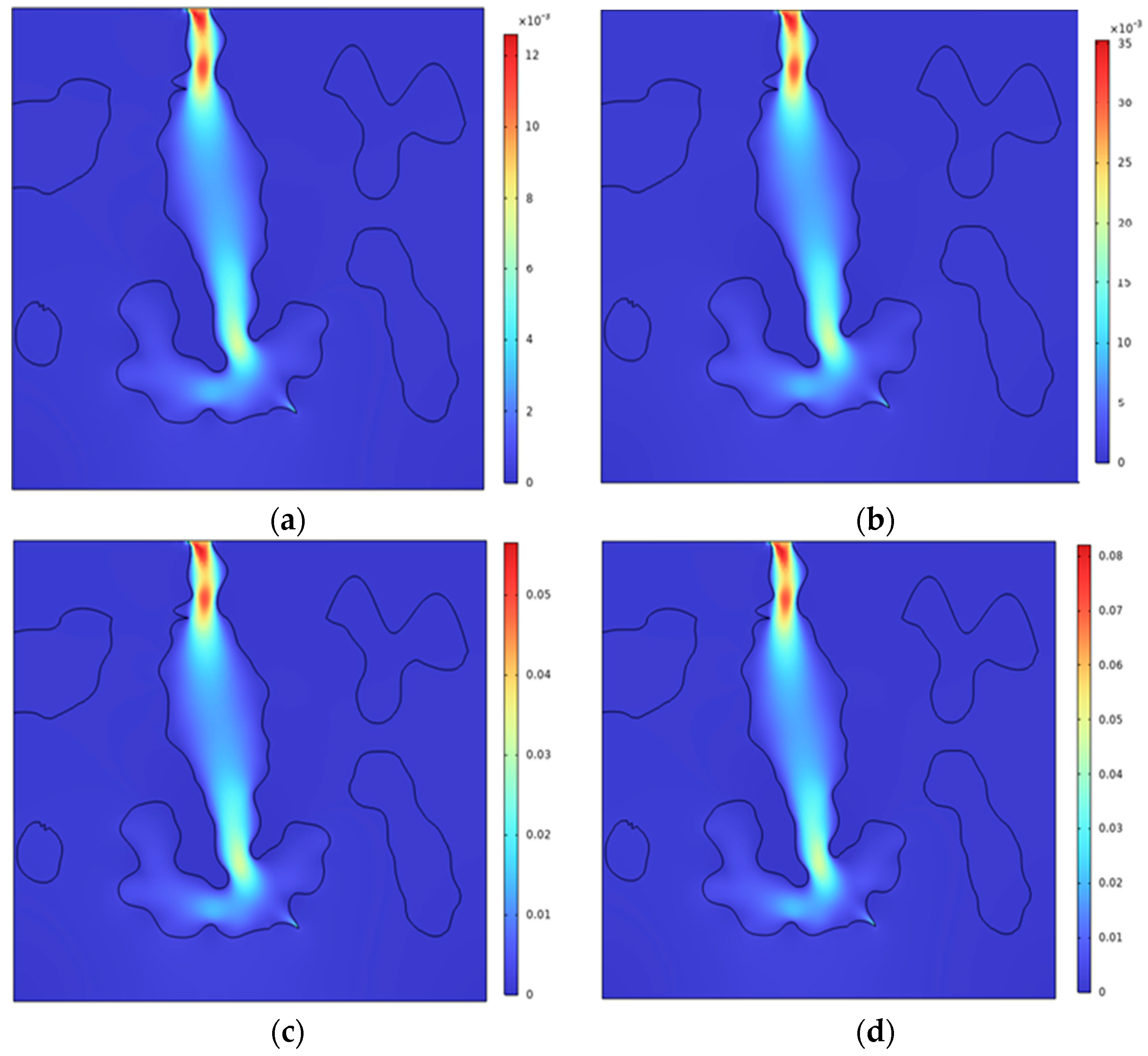
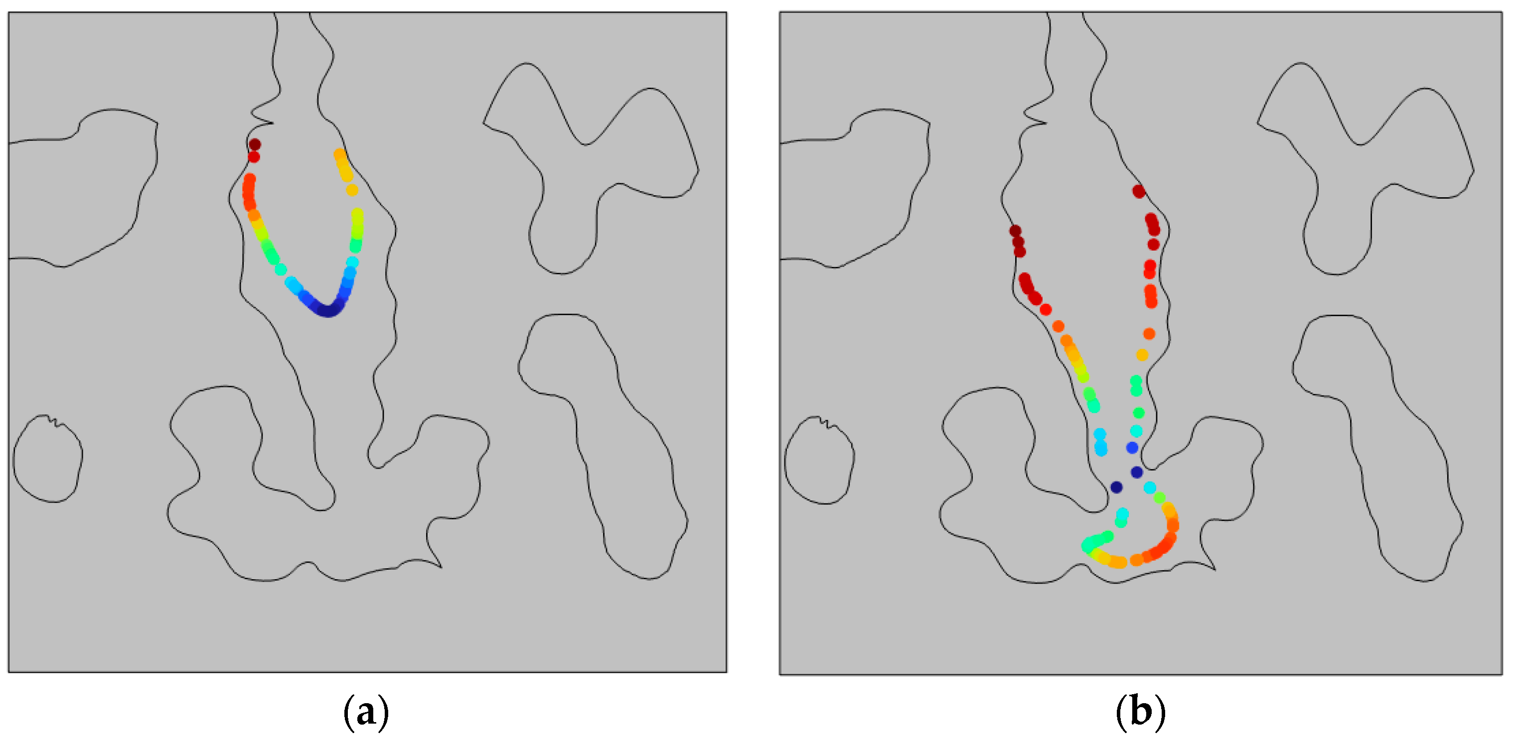
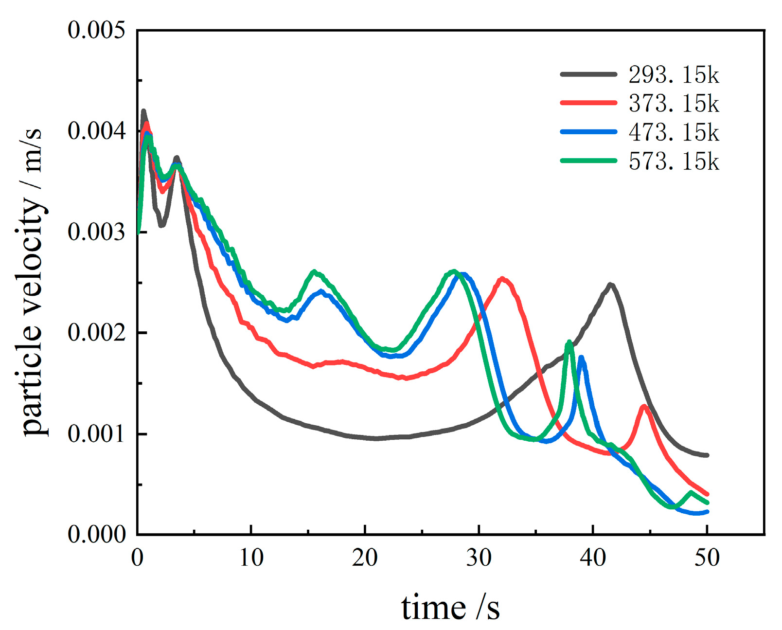
4.2.2. Effect of Different Temperatures

This section investigates the effect of temperature on the migration process of the temporary plugging particles in the carbonate thermal storage fractures, in which heat exchange could occur between the high-temperature formation and the porous medium, fracturing fluid, and temporary plugging particles during their migration process. Temperatures were assumed to be 293.15 K, 373.15 K, 473.15 K, and 573.15 K. Variations in the velocity of movement within individual particles were analysed.
Figure 11 shows the velocity profiles of temporarily plugged particles at different temperatures. The initial velocity of the particles was consistent with the liquid velocity, and the collision rebound and inter-particle collision in the early stage of flowing through the narrow fracture made the particle velocity appear as a wave peak, and there was another wave peak when it reached the fracture and collided with the bottom wall of the fracture. It was found that with the increase in the rock temperature, the velocity of the temporary plugging particles in the fracture increased, and the time for the particles to reach the fracture accelerated. This could have been because the increase in temperature gradually reduced the viscosity of the fracturing fluid so that the velocity of the fluid and the particles increased, and, in addition, the temperature also reduced the energy of the collision of the particles so that the velocity of the particles increased.

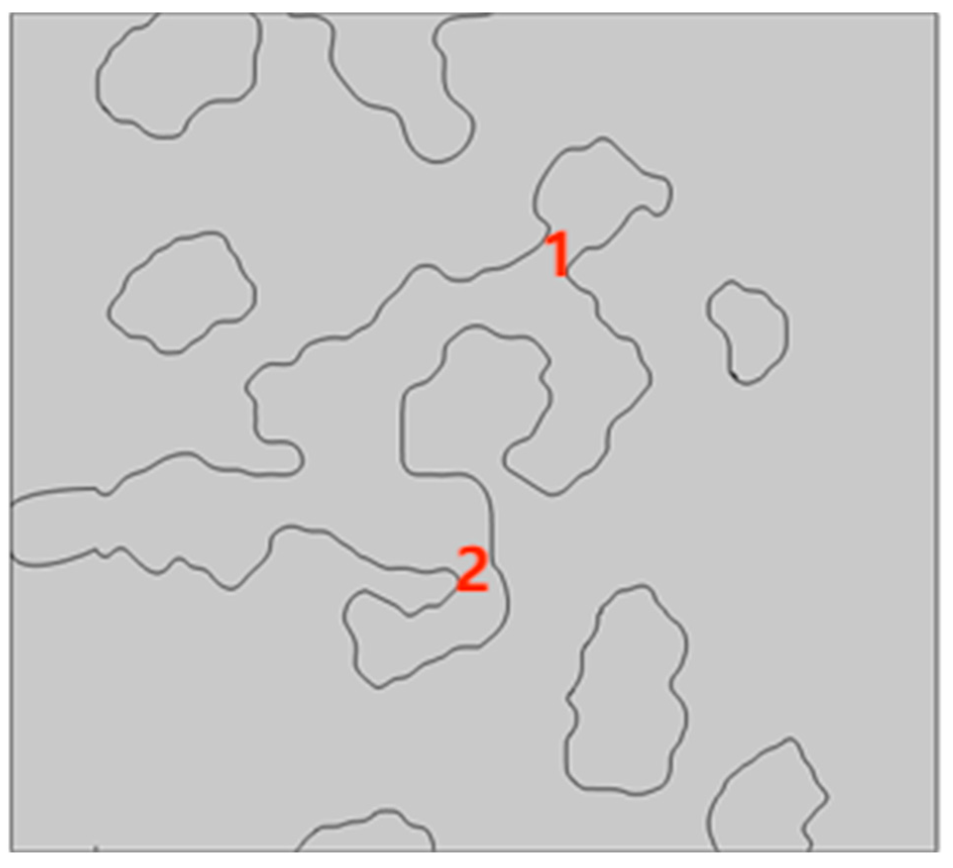
4.3. Simulation of the Temporary Plugging of Complex Fractures

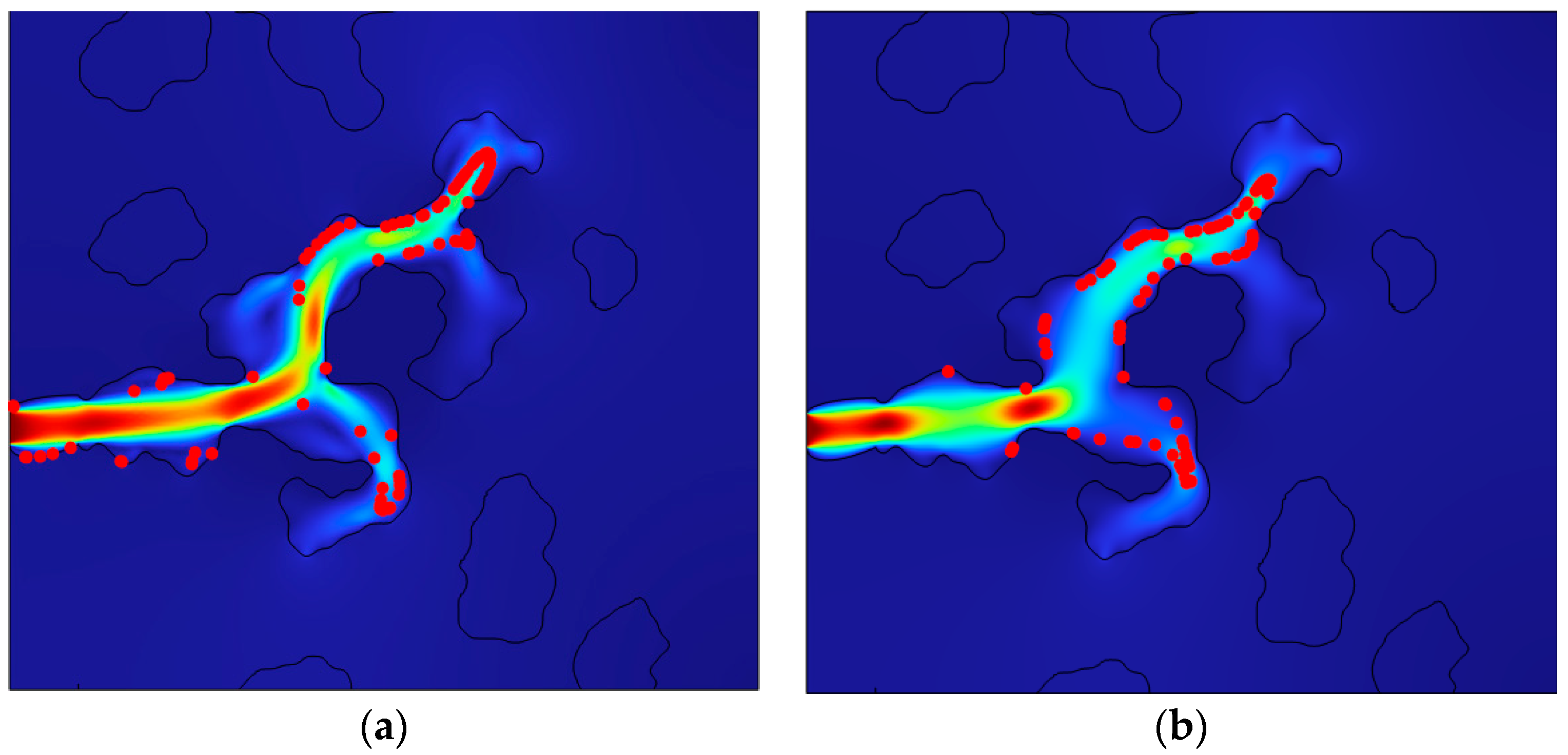
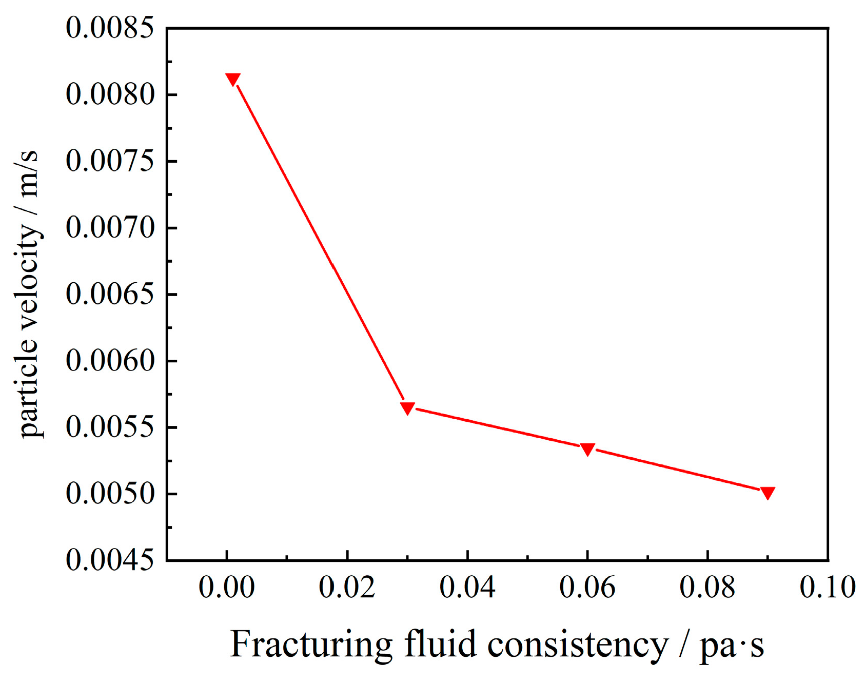
4.3.1. Effect of Different Fracturing Fluid Viscosities

In order to maintain a certain amount of plugging particles in the fracture and reduce dispersion during transport, a high-viscosity polymer fracturing fluid is usually used for fracturing. In this study, the transport of plug particles in the fracture was investigated with different viscosity fracturing fluids. In actual channel fracturing operations, the fracturing fluid viscosity is usually kept constant and pulse injection is used. In this study, only the effect of a single factor was investigated and continuous injection was used.
Figure 12 shows the trajectories of temporary plugging particles with different fracturing fluid viscosities at the same time. From the figure, we can see that when the viscosity of the fracturing fluid was low, the particles settled in the front part of the fracture, and the high-viscosity fracturing fluid caused the temporary plugging particles to bond with each other to form temporary plugging particle clusters, reducing dispersion during the transport process. With the increase in viscosity, the velocity of the particles decreased, and the time for the particles to reach the fracture increased(Figure 13).

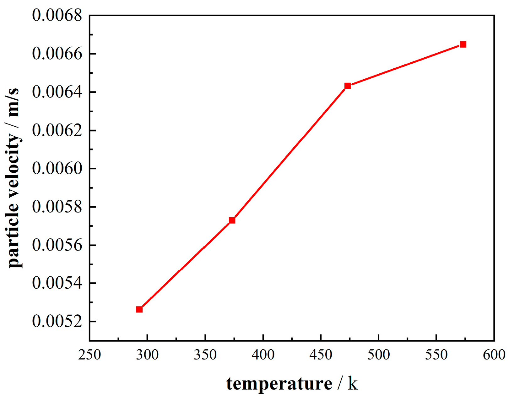
4.3.2. Effect of Different Temperatures

The aim of this section is to investigate the effect of temperature on the transport of temporarily plugged particles in complex cracks with temperature parameters ranging from 293.15 K to 573.15 K. Unlike the study of individual particle velocities at the fracture slit, here, we are concerned with the effect of temperature on the average particle velocity. Figure 14 shows that the particle velocity tended to increase as the temperature increased, but the slope of the increase in particle velocity decreased from about 50% to 22% when the temperature reached 200 °C.

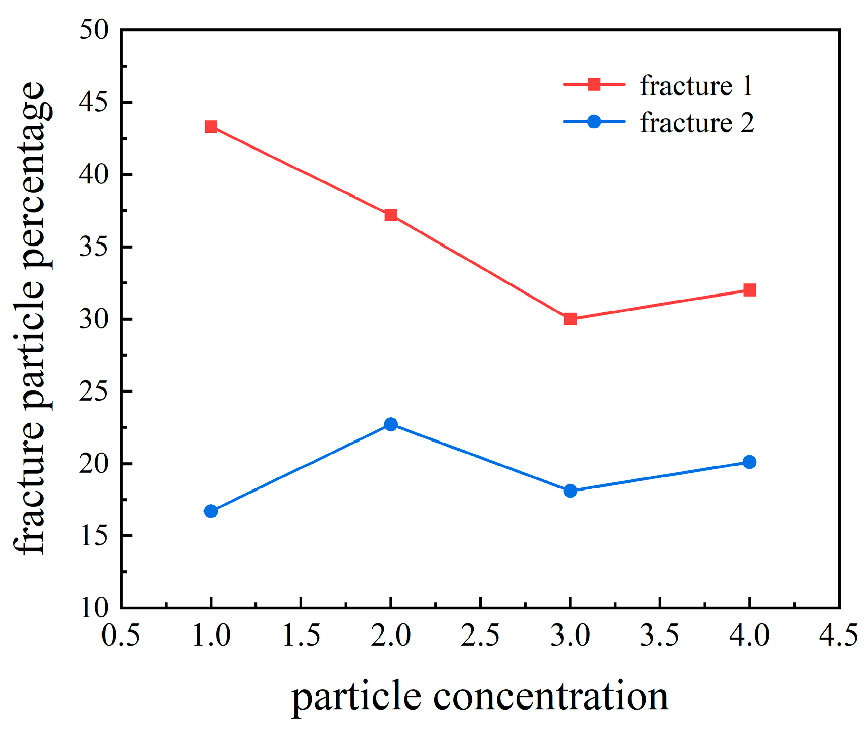
4.3.3. Effect of the Concentration of Temporary Plugging Particles

We investigated the effect of the concentration of particles on particle transport and sealing. We counted the number of particles arriving at the fractures to characterise the influence of temporary plugging, as shown in Figure 15. The upper fracture of the model was recorded as fracture 1 and the lower fracture was recorded as fracture 2. From Figure 16, we can see that as the concentration of the temporary plugging particles increased, the number of particles arriving at fracture 1 increased, and fracture 1 was temporarily plugged, but, at the same time, the number of particles arriving at fracture 2 also increased, plugging fracture 2, resulting in the entire crack being plugged and not having the desired temporary plugging effect.
Figure 17 shows that the particles arriving at the two fractures were in proportion with the total number of particles, although the number of particles arriving at fracture 1 increased with the increase in particle concentration. But, the proportion of particles decreased while the proportion of the particles at fracture 2 was on an increasing trend in general. The rate of decrease of the proportion of the particles at fracture 1 was much larger than the rate of increase of the particles at fracture 2. If the concentration of the temporary plugging agent was too high, it complicated the fracturing operation, resulting in material waste and a poor temporary plugging effect. As a result, the concentration of plugging particles should be determined using the actual working conditions encountered during the construction process.

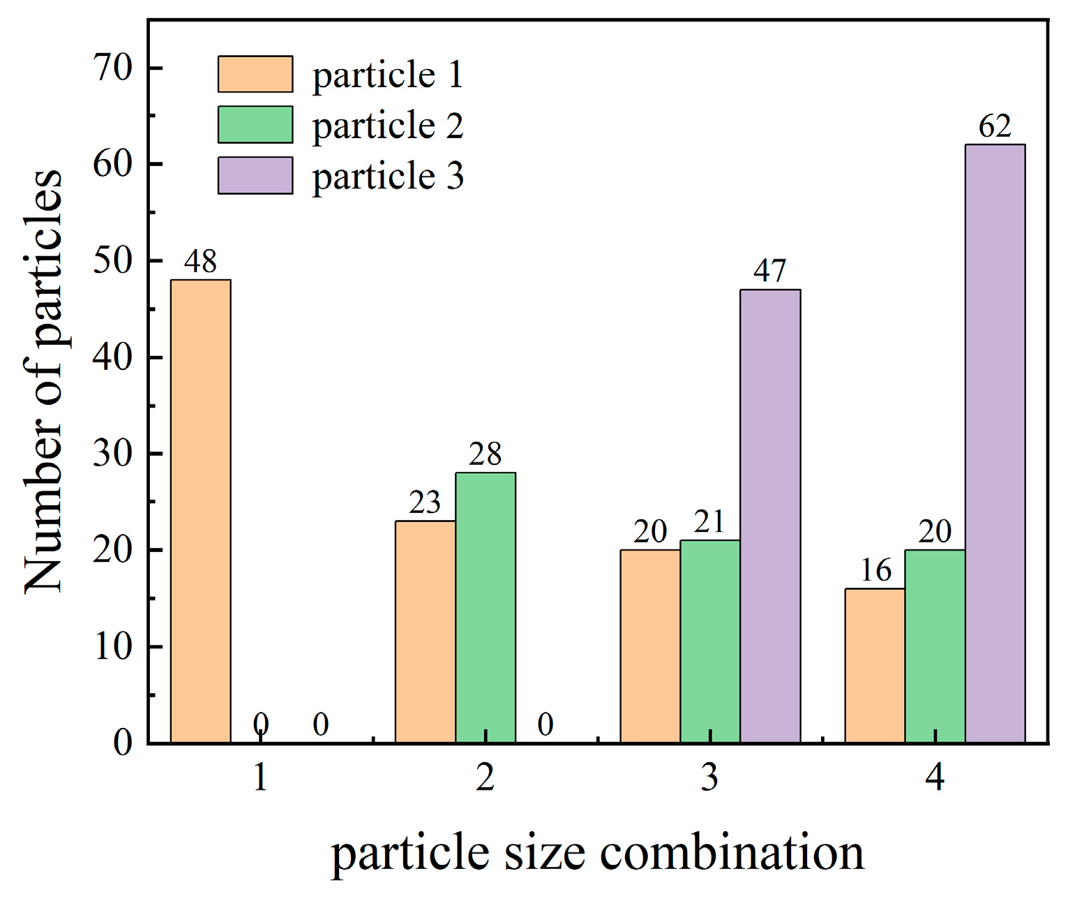
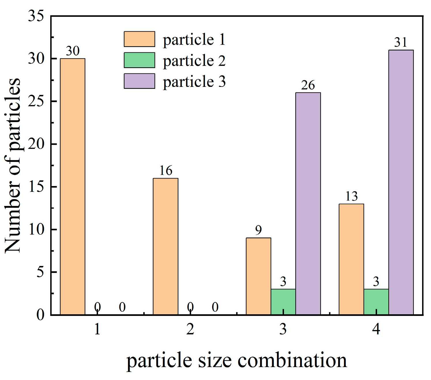
4.3.4. Effect of Different Particle Size Combinations

One of the key stages in plugging fracturing technology is the achievement of stable plugging, particularly when particles can be transported consistently to the fracture site. In this study, the transport and sealing process of plugging particles with different particle sizes (one size, two sizes, and all three sizes at the same time) was measured by simulation (Table 2).
Figure 18, Figure 19 and Figure 20 show the trajectory of particles with different particle size combinations and the number of particles reaching fractures with different particle size combinations, respectively. As can be seen from the figure, with the same concentration, the overall number of particles with multiple particle size combinations reaching fracture 1 increased, but the number of large-size particles decreased, and most of the increase was in the number of small-size particles, but the proportion of different particles was more reasonable. The number of large-size particles reaching fracture 2 decreased, which resulted in a better temporary plugging effect. In addition, we compared the particle size ratio of the three sizes, and, although the number of small particles increased, there was no significant increase in the plugging effect.

5. Conclusions

  • Transient plugging particle transport in thermal storage fractures can be simulated using CFD-DEM methods
This study used a two-way coupled CFD-DEM calculation to build a multiphase flow model for the transport process of temporary plugging particles in carbonate thermal storage. The model’s grid independence and viability were confirmed. This study examined the effects of various parameters, including formation temperature, fracturing fluid viscosity, the concentration of temporary plugging particles, and particle size combinations, on the transportation and sealing of particles at the fracture opening location and within the complex fracture.
  • High-viscosity fracking fluids can cause the dispersion of temporary plugging particles during transport
The injection displacement and viscosity of the fracturing fluid played an important role in determining the transport efficiency of the temporary plugging particles. High-viscosity slurries may cause the plugging particles to bond with each other to form clusters of plugging particles that reduce dispersion during transport, causing the velocity of the plugging particles to decrease. When the injection displacement is too high, it may cause both sides of the fracture to be plugged, failing to achieve the effect of temporary plugging.
  • Different combinations of particle sizes give better results for temporary plugging particles
Particle size combination is the key factor determining the success of plugging. A high concentration of particles does not result in a better plugging effect. The use of different combinations of particle sizes is significantly better than temporary plugging with a single particle.
  • High temperatures increase particle velocity
Higher temperatures cause the plugging particles to move faster because higher temperatures increase the fracturing fluid flow rate, which speeds up the movement of the plugging particles and allows them to reach the fracture faster for plugging.

Author Contributions

Conceptualization, G.F.; methodology, G.F.; software, A.T.; validation, A.T.; formal analysis, J.T.; investigation, J.T.; resources, D.W.; data curation, A.T.; writing—original draft preparation, A.T.; writing—review and editing, A.T.; visualization, A.T.; supervision, D.W.; project administration, G.F.; funding acquisition, G.F. All authors have read and agreed to the published version of the manuscript.

Funding

This research was funded by the Jiangsu Province Carbon Peak Carbon Neutral Technology Innovation Project in China (BE2022034).

Data Availability Statement

The original contributions presented in the study are included in the article, further inquiries can be directed to the corresponding authors.

Conflicts of Interest

The authors declare no conflict of interest.

References

  1. Li, G.; Wu, X.; Song, X.; Zhou, S.; Li, M.; Zhu, H.; Kong, Y.; Huang, Z. Status and Challenges of Dry hot Rock Geothermal Resource Extraction Technology. Pet. Sci. Bull. 2022, 7, 343–364. [Google Scholar]
  2. Wang, J.; Hu, S.; Pang, Z.; He, L.; Zhao, P.; Zhu, C.; Rao, S.; Tang, X.; Kong, Y.; Luo, L.; et al. Assessment of Geothermal Resource Potential of Dry Hot Rocks in Mainland China. Sci. Technol. Her. (Newsp.) 2012, 30, 25–31. [Google Scholar]
  3. Xu, T.; Wang, Y.; Feng, G. Research Progress and Development Prospects of Deep Supercritical Geothermal Resources. Gas Ind. 2021, 41, 155–167. [Google Scholar] [CrossRef]
  4. Yang, Y.; Fu, G.; Zhao, J.; Gu, L. Heat Production Capacity Simulation and Parameter Sensitivity Analysis in the Process of Thermal Reservoir Development. Energies 2023, 16, 7258. [Google Scholar] [CrossRef]
  5. Guo, T.; Gong, F.; Wang, X.; Lin, Q.; Qu, Z.; Zhang, W. Performance of enhanced geothermal system (EGS) in fractured geothermal reservoirs with CO2 as working fluid. Appl. Therm. Eng. 2019, 152, 215–230. [Google Scholar] [CrossRef]
  6. Song, G.; Song, X.; Xu, F.; Li, G.; Shi, Y.; Ji, J. Contributions of Thermo-Poroelastic and Chemical Effects to the Production of Enhanced Geothermal System Based on Thermo-Hydro-Mechanical-Chemical Modeling. J. Clean. Prod. 2022, 377, 134471. [Google Scholar] [CrossRef]
  7. Li, M.; Zhou, F.; Sun, Z.; Dong, E.; Zhuang, X.; Yuan, L.; Wang, B. Experimental Study on Plugging Performance and Diverted Fracture Geometry during Different Temporary Plugging and Diverting Fracturing in Jimusar Shale. J. Pet. Sci. Eng. 2022, 215, 110580. [Google Scholar] [CrossRef]
  8. Wang, D.B.; Zhou, F.J.; Li, Y.P.; Yu, B.; Martyushev, D.; Liu, X.F.; Wang, M.; He, C.M.; Han, D.X.; Sun, D.L. Numerical Simulation of Fracture Propagation in Russia Carbonate Reservoirs during Refracturing. Pet. Sci. Engl. Ed. 2022, 19, 2781–2795. [Google Scholar] [CrossRef]
  9. Trumble, M.; Sinkey, M.; Meehleib, J. Got Diversion? Real Time Analysis to Identify Success or Failure. In Proceedings of the SPE Hydraulic Fracturing Technology Conference and Exhibition, The Woodlands, TX, USA, 5–7 February 2019. [Google Scholar] [CrossRef]
  10. Wang, B.; Zhou, F.; Liang, T.; Wang, D.; Gao, L.; Hu, J. Evaluations of Fracture Injection Pressure and Fracture Mouth Width during Separate-Layer Fracturing with Temporary Plugging. Math. Probl. Eng. 2018, 2018, 3489656. [Google Scholar] [CrossRef]
  11. Zhou, F.; Liu, Y.; Yang, X.; Zhang, F.; Xiong, C.; Liu, X. Case Study: YM204 Obtained High Petroleum Production by Acid Fracture Treatment Combining Fluid Diversion and Fracture Reorientation. In Proceedings of the 8th European Formation Damage Conference, Scheveningen, The Netherlands, 27–29 May 2009; Society of Petroleum Engineers: Kuala Lumpur, Malaysia, 2019. [Google Scholar] [CrossRef]
  12. Allison, D.; Curry, S.; Todd, B. Restimulation of Wells Using Biodegradable Particulates as Temporary Diverting Agents. In Proceedings of the Canadian Unconventional Resources Conference, Calgary, AB, Canada, 15–17 November 2011; OnePetro: Richardson, TX, USA, 2011. [Google Scholar] [CrossRef]
  13. Yang, B. Study on the Formation Mechanism of Hydraulic Fracturing with Multi-Branch Seams. Master’s Thesis, Northeast Petroleum University, Da Qing, China, 2017. [Google Scholar]
  14. Li, B.; Zhou, F.; Yuan, L.; Li, H.; Cheng, J.; Tan, Y.; Zhang, Y.; Xian, B.; Fan, W. Experimental Investigation on the Fracture Diverting Mechanism and Plugging Efficiency Using 3D Printing Fractures. In Proceedings of the 53rd U.S. Rock Mechanics/Geomechanics Symposium, New York, NY, USA, 23–26 June 2019; OnePetro: Richardson, TX, USA, 2019. [Google Scholar]
  15. Zhang, R.; Hou, B.; Tan, P.; Muhadasi, Y.; Fu, W.; Dong, X.; Chen, M. Hydraulic Fracture Propagation Behavior and Diversion Characteristic in Shale Formation by Temporary Plugging Fracturing. J. Pet. Sci. Eng. 2020, 190, 107063. [Google Scholar] [CrossRef]
  16. Li, M.-H.; Zhou, F.-J.; Liu, J.-J.; Yuan, L.-S.; Huang, G.-P.; Wang, B. Quantitative Investigation of Multi-Fracture Morphology during TPDF through True Tri-Axial Fracturing Experiments and CT Scanning. Pet. Sci. 2022, 19, 1700–1717. [Google Scholar] [CrossRef]
  17. Li, Y.; Zhang, Q.; Zou, Y. Experimental Investigation of the Growth Law of Multi-Fracture during Temporary Plugging Fracturing within a Stage of Multi-Cluster in a Horizontal Well. Processes 2022, 10, 637. [Google Scholar] [CrossRef]
  18. Chen, X.; Zhao, L.; Liu, P.; Du, J.; Wang, Q.; An, Q.; Chang, B.; Luo, Z.; Zhang, N. Experimental Study and Field Verification of Fracturing Technique Using a Thermo-Responsive Diverting Agent. J. Nat. Gas Sci. Eng. 2021, 92, 103993. [Google Scholar] [CrossRef]
  19. McCartney, E.S.; Kennedy, R.L. A Family of Unique Diverting Technologies Increases Unconventional Production and Recovery in Multiple Applications—Initial Fracturing, Refracturing, and Acidizing. In Proceedings of the SPE Hydraulic Fracturing Technology Conference, The Woodlands, TX, USA, 9–11 February 2016; OnePetro: Richardson, TX, USA, 2016. [Google Scholar] [CrossRef]
  20. Arnold, D.; Fragachan, F. Eco-Friendly Degradable Mechanical Diverting Agents for Combining Multiple-Staged Vertical Wells: Case History from Wasatch Formation. In Proceedings of the Abu Dhabi International Petroleum Exhibition and Conference, Abu Dhabi, United Arab Emirates, 10–13 November 2014; OnePetro: Richardson, TX, USA, 2014. [Google Scholar] [CrossRef]
  21. Vidma, K.; Abivin, P.; Dunaeva, A.; Panga, M.; Nikolaev, M.; Usoltsev, D.; Mayo, J.T. Far-Field Diversion Technology to Prevent Fracture Hits in Tightly Spaced Horizontal Wells. In Proceedings of the SPE Annual Technical Conference and Exhibition, Dallas, TX, USA, 24–26 September 2018; OnePetro: Richardson, TX, USA, 2018. [Google Scholar] [CrossRef]
  22. Shahri, M.P.; Huang, J.; Smith, C.S.; Fragachán, F.E. An Engineered Approach to Design Biodegradables Solid Particulate Diverters: Jamming and Plugging. In Proceedings of the SPE Annual Technical Conference and Exhibition, San Antonio, TX, USA, 9–11 October 2017; OnePetro: Richardson, TX, USA, 2017. [Google Scholar] [CrossRef]
  23. Hu, X.; Wu, K.; Song, X.; Yu, W.; Tang, J.; Li, G.; Shen, Z. A New Model for Simulating Particle Transport in a Low-Viscosity Fluid for Fluid-Driven Fracturing. AIChE J. 2018, 64, 3542–3552. [Google Scholar] [CrossRef]
  24. Zhao, J.; Zhao, X.; Zhao, J.; Cao, L.; Hu, Y.; Liu, X. Coupled Model for Simulating Proppant Distribution in Extending Fracture. Eng. Fract. Mech. 2021, 253, 107865. [Google Scholar] [CrossRef]
  25. Yuan, L.; Zhou, F.; Li, M.; Wang, B.; Bai, J. Experimental and Numerical Investigation on Particle Diverters Transport during Hydraulic Fracturing. J. Nat. Gas Sci. Eng. 2021, 96, 104290. [Google Scholar] [CrossRef]
  26. Gong, Y.; Mehana, M.; El-Monier, I.; Viswanathan, H. Proppant placement in complex fracture geometries: A computational fluid dynamics study. J. Nat. Gas Sci. Eng. 2020, 79, 103295. [Google Scholar] [CrossRef]
  27. Han, K.; Feng, Y.T.; Owen, D.R.J. Coupled lattice Boltzmann and discrete element modelling of fluid–particle interaction problems. Comput. Struct. 2007, 85, 1080–1088. [Google Scholar] [CrossRef]
  28. Wu, C.-H.; Yi, S.; Sharma, M.M. Proppant Distribution Among Multiple Perforation Clusters in a Horizontal Wellbore. In Proceedings of the SPE Hydraulic Fracturing Technology Conference and Exhibition, The Woodlands, TX, USA, 24–26 January 2017; OnePetro: Richardson, TX, USA, 2017. [Google Scholar] [CrossRef]
  29. Ren, L.; Lin, C.; Zhao, J.; Lin, R.; Wu, J.; Wu, J.; Hu, Z. Numerical Simulation of Coated Proppant Transport and Placement in Hydraulic Fractures Based on CFD-DEM. In Petroleum Science and Technology; Taylor and Francis: Abingdon, UK, 2023; pp. 1–21. [Google Scholar] [CrossRef]
  30. Sui, W.; Tian, Y.; Zheng, Y.; Dong, K. Modeling Temporary Plugging Agent Transport in the Wellbore and Fracture with a Coupled Computational Fluid Dynamics–Discrete Element Method Approach. Energy Fuels 2021, 35, 1422–1432. [Google Scholar] [CrossRef]
  31. Wang, D.; Qin, H.; Zheng, C.; Sun, D.; Yu, B. Transport Mechanism of Temporary Plugging Agent in Complex Fractures of Hot Dry Rock: A Numerical Study. Geothermics 2023, 111, 102714. [Google Scholar] [CrossRef]
  32. Zheng, C.; Wang, D.; Wang, Q.; Sun, S.; Sun, D.; Yu, B. The Migration Mechanism of Temporary Plugging Agents in Rough Fractures of Hot Dry Rock: A Numerical Study. Phys. Fluids 2024, 36, 023323. [Google Scholar] [CrossRef]
  33. Anderson, T.B.; Jackson, R. Fluid Mechanical Description of Fluidized Beds. Equ. Motion. Ind. Eng. Chem. Fund. 1967, 6, 527–539. [Google Scholar] [CrossRef]
  34. Guo, T.; Tang, S.; Liu, S.; Liu, X.; Zhang, W.; Qu, G. Numerical Simulation of Hydraulic Fracturing of Hot Dry Rock under Thermal Stress. Eng. Fract. Mech. 2020, 240, 107350. [Google Scholar] [CrossRef]
  35. Li, Z. Mechanisms of Proppant Transport and Pressure Embedding in Fractured Coal Seams. Ph.D. Thesis, China University of Mining and Technology, Xuzhou, China, 2024. [Google Scholar]
Figure 1. Flowchart of CFD-DEM model.
Energies 17 03283 g001
Figure 2. Geometric modelling of complex fractures: (a) fracture slit plugging model; (b) complex fracture temporary plugging model.
Energies 17 03283 g002
Figure 3. Mesh generation diagram of the model: (a) fracture slit plugging model; (b) complex fracture temporary plugging model.
Energies 17 03283 g003
Figure 4. Comparison of particle velocity simulation results with different mesh numbers.
Energies 17 03283 g004
Figure 5. Comparison of test and simulation results.
Energies 17 03283 g005
Figure 6. Fracturing fluid flowed into the matrix: (a) fracture slit; (b) complex fracture.
Energies 17 03283 g006
Figure 7. Particle trajectories for temporary plugging of fracture slit: (a) early stage; (b) late stage.
Energies 17 03283 g007
Figure 8. Particle trajectories for temporary plugging of complex fracture: (a) early stage; (b) late stage.
Energies 17 03283 g008
Figure 9. Fluid velocity at different displacements: (a) injection displacement at 10 mL/min; (b) injection displacement at 30 mL/min; (c) injection displacement at 50 mL/min; (d) injection displacement at 70 mL/min.
Energies 17 03283 g009
Figure 10. Particle trajectories at different injection displacements: (a) injection displacement at 10 mL/min; (b) injection displacement at 30 mL/min; (c) injection displacement at 50 mL/min; (d) injection displacement at 70 mL/min.
Energies 17 03283 g010aEnergies 17 03283 g010b
Figure 11. Effect of different temperatures (293.15 K, 373.15 K, 473.15 K, 573.15 K) on the velocity of temporarily blocked particles.
Energies 17 03283 g011
Figure 12. Particle trajectories at different fracturing fluid viscosities: (a) fracturing fluid viscosity of 0.001 pa·s; (b) fracturing fluid viscosity of 0.03 pa·s; (c) fracturing fluid viscosity of 0.06 pa·s; (d) fracturing fluid viscosity of 0.09 pa·s.
Energies 17 03283 g012aEnergies 17 03283 g012b
Figure 13. Particle velocity for different fracturing fluid viscosities (0.001 pa·s, 0.03 pa·s, 0.06 pa·s, 0.09 pa·s).
Energies 17 03283 g013
Figure 14. Effect of different temperatures (293.15 K, 373.15, 473.15, 573.15) on particle velocity in complex cracks.
Energies 17 03283 g014
Figure 15. Marking diagram for temporary plugging of fractures.
Energies 17 03283 g015
Figure 16. Number of particles reaching the crack at different concentrations of plugging particles (1%, 2%, 3%, 4%).
Energies 17 03283 g016
Figure 17. Plot of the number of particles reaching the cracks as a percentage of the total number of particles for different particle concentrations (1%, 2%, 3%, 4%).
Energies 17 03283 g017
Figure 18. Particle trajectories without size combinations: (a) Number 1; (b) Number 2; (c) Number 3; (d) Number 4.
Energies 17 03283 g018
Figure 19. Number of particles reaching fracture 1 with different particle size combinations.
Energies 17 03283 g019
Figure 20. Number of particles reaching fracture 2 with different particle size combinations.
Energies 17 03283 g020
Table 1. Parameters of modelled fluids, particles, and porous media.
ParametersUnitsValues
Fracturing fluid densitykg/m31200
Fracturing fluid viscosityPa s0.03
Initial fluid temperaturek293.15
Initial fluid displacementmL/min15
Density of plugged particleskg/m32200
Plugging particle sizecm0.05
Matrix porosity-0.05
Matrix penetration ratem25 × 10−18
Matrix densitykg/m32800
Matrix thermal conductivityW/(m k)2
Matrix heat capacityJ/(kg k)920
Table 2. Parameters of different particle size combinations.
NumberParticle Size CombinationParticle DiameterParticle Number Ratio
1Single particle size0.051
2Two particle sizes0.05, 0.031:4
3Three particle sizes0.05, 0.03, 0.011:1:3
4Three particle sizes0.05, 0.03, 0.011:1:4
Disclaimer/Publisher’s Note: The statements, opinions and data contained in all publications are solely those of the individual author(s) and contributor(s) and not of MDPI and/or the editor(s). MDPI and/or the editor(s) disclaim responsibility for any injury to people or property resulting from any ideas, methods, instructions or products referred to in the content.

