Article

Unified Paradigm of Start-Up Strategy for Pumped Storage Hydropower Stations: Variable Universe Fuzzy PID Controller and Integrated Operation Optimization

1
Changjiang River Scientific Research Institute, Changjiang Water Resources Commission, Wuhan 430010, China
2
Key Laboratory of River Regulation and Flood Control in the Middle and Lower Reaches of the Yangtze River of Ministry of Water Resources, Wuhan 430010, China
3
School of Civil and Hydraulic Engineering, Hua Zhong University of Science and Technology, Wuhan 430074, China
4
Power China Huadong Engineering Corporation Limited, Hangzhou 311122, China
*
Author to whom correspondence should be addressed.
Energies 2024, 17(13), 3293; https://doi.org/10.3390/en17133293
Submission received: 25 April 2024 / Revised: 20 June 2024 / Accepted: 24 June 2024 / Published: 4 July 2024

Abstract

:
A pumped storage unit is a crucial guarantee in the pursuit of increased clean energy, especially in the progressively severe circumstances of low energy utilization and poor coordination of the integration of volatile renewable energy. However, due to their bidirectional operation design, pumped turbines possess an S-characteristic attribution, wherein the unsteady phenomena of unit vibration, pressure pulsation, and cavitation erosion happen during the start-up process and greatly impact the stable connection to the power grid. Therefore, a systematic study concentrating on an optimal unified paradigm of a start-up strategy for a pumped storage plant is conducted. Model construction, effective analysis, controller design, and collaborative optimization are sequentially expounded. Firstly, a refined start-up nonlinear model of a pumped storage plant with complex boundary conditions is constructed, wherein the delay time of frequency measurement, saturation, and dead zone features are comprehensively taken account. Furthermore, a variable universe fuzzy PID controller and its operation laws are proposed and specifically designed for the speed governing system of the pumped storage plant; the control quality and anti-disturbance performance are verified by a no-load frequency disturbance experiment. On this basis, taking speed overshoot for stationarity and speed rising time for rapidity, a novel open–close loop collaborative fuzzy control strategy is proposed with rotational speed feedback and a variable universe fuzzy PID control. The experiment results show that the proposed unified paradigm has better control performance in various performance indexes, and more balanced control quality and dynamic performance under various complex start-up conditions, which has great application value for ensuring the unit’s timely response to the power grid regulation task and improving the operating stability of the power system.

1. Introduction

Due to the scarcity and exhaustibility of fossil energy, consensus has been reached that renewable energy expansion could be an efficient and practicable path to achieving sustainable development [1,2]. More critically, it helps to maintain energy independence [3], mitigate climate change [4], and reduce environmental impacts associated with fossil fuel consumption [5,6]. In this regard, China has made commitments concerning the strategic target of “carbon emission peak and carbon neutrality” [7]. The momentum toward the construction of variable renewable energy sources is increasing, which is reflected in the continually growing share of wind and solar power [8]. At the same time, the emerging imbalance between production and consumption brings security concerns along with energy structure adjustment. These volatile energy sources are subject to weather conditions and pose potential threats to the stability of power grid systems [9,10]. Hence, the balancing act involving variable renewable energy sources has become a crucial topic in the energy industry all over the world.
Energy storage technology acts to alleviate the contradiction between renewable supply and electricity demand across various timescales, further achieving the purpose of modulating and stabilizing the power system [11,12]. Among them, pumped storage units (PSUs) are probably the most economical and mature tool for energy storage [13], having shouldered regulation duties like load-leveling [14], frequency modulation [15], and emergency response in power systems [16]. Given their flexible condition conversion and cost-competitive potential, it is reasonable to expect great breakthroughs for pumped storage plants in grid scheduling and security [17].
In a bid to adjust the power system more efficiently, pumped storage plants undergo numerous transient processes, especially the start-up process [18], which requires the units to rapidly switch from stationary conditions to steady states while maintaining working parameters within the control range [19]. The control quality of PSUs could not be neglected, and a stable start-up process is therefore particularly important. In addition, the hydraulic interference brought by the complex water transmission system layout makes the high-quality control of the start-up transient process more complicated [20]. In this paper, a unified paradigm for a start-up operation strategy for pumped storage plants is proposed, the variable universe fuzzy PID controller is designed to adaptively change control parameters in order to be suitable for multiple start-up conditions, and the open-loop control regarding the guide vane and close-loop control concerning the controller are organically combined to induce collaborative optimization. Prior to this, the influence of operating parameters related to start-up operation is first explored.
The primary focus in designing a start-up strategy is model construction. A refined model can accurately capture the characteristics of the transient process and provide a solid foundation for subsequent research [21,22]. Fruitful research has been conducted and is summarized as follows. Zhang et al. [23] constructed a linearized reduced order dynamic model of pumped storage hydropower plants, considering the elastic water effects. Hu et al. [24] performed one-dimensional rigid column simulation to investigate hydraulic oscillations. Zhang et al. [25] innovatively presented a transient model reflecting the coupling effects. However, for the start-up processes, with features such as complex nonlinearity and time variance, performance cannot be accurately depicted by these simplified models. Apart from that, the core component of energy conversion, i.e., PSU, has a significant influence on the calculation precision of the transient process as well. Although Zuo et al. [26] and Xu et al. [27] explored the dynamic equations of the pumped turbine and achieved practical suggestions, the S-shaped characteristic caused by the reversible design raises difficulties for transient analysis. In such a situation, the start-up transient process model of the pumped storage plant is established considering the hydraulic interaction of multi-units sharing common conduits. Moreover, the backpropagation neural-network-fused Suter transformation is employed to grasp the potential associations of complete characteristic curves.
The second step in the unified paradigm for a start-up process is to establish effective control policies. For a typical start-up strategy, two stages constitute the control process [28]. The former, named open-loop, directly operates the guide vane opening according to the reference trajectory and the latter, called close-loop, attaches the controller and feedback signal to obtain a steady rotational speed. Hou et al. [29] placed emphasis on the previous stage and verified that two-phase polyline direct control achieves better solutions in terms of start-up stability. Li et al. [30] paid attention to the close-loop stage and adopted a fractional order PID controller; the results show that significant improvement in the performance of water hammer pressure had been acquired. Nevertheless, few researchers comprehensively consider the two processes as a whole, and the design of the controller is not sufficient to cover multiple start-up processes. One prominent problem is poor working conditions and adaptability. Specifically speaking, Xu et al. [31] studied single-unit start-up conditions under a low head area, and Lei et al. [32] investigated the optimal strategy for successive start-up conditions from symmetrical and asymmetrical structural viewpoints. The existing optimization procedure for optimal control strategy was carried out independently for a specific condition, which leads to a unique set of optimal parameters in different conditions. There is an evolutionary relationship between the two mentioned operating conditions, such that another unit sharing same hydraulic system might start and the single-unit start-up conditions can be evolved to successive start-up processes, under which circumstance the unreasonable control parameters will cause drastic speed fluctuation and affect grid connection.
Motivated by the above discussions, this paper concentrates on the unified paradigm of optimal start-up strategy. Three advantages make the research attractive compared with the prior works. (1) A refined nonlinear model of a pumped storage plant is applied to multiple start-up processes involving hydraulic interference. (2) The effects of the operational parameters on the start-up process are quantitatively illustrated for the first time, and the harshest working combination is specified for the follow-up study. (3) A variable universe fuzzy PID controller propitious to a speed governing system is proposed for the purpose of improving condition adaptability with the premise of control precision, and the novel optimization scheme is designed comprehensively, taking into account open–close stages and multiple start-up conditions. With high engineering application values, the unified paradigm can reduce investment and safety risks caused by the mismatching of controller parameters and working conditions.
The organization structure for the rest of this paper is as follows. In Section 2, a refined start-up model of pumped storage plants involving hydraulic interference and multiple nonlinear components is established. Section 3 quantitatively illustrates the effects of the operation parameters on the start-up process, and the harshest working conditions are identified. Section 4 depicts the variable universe fuzzy PID controller, and the optimization procedure is delineated. In Section 5, the unified paradigm is synthetically evaluated by applying it to a real case. The whole paper is summarized in Section 6 and further research orientations are suggested. The research flowchart of this paper is presented in Figure 1.

2. Refined Start-Up Model of Pumped Storage Plants

The pumped storage plant is an intricate nonlinear system with a high degree of hydraulic–mechanical–magnetic–electric coupling [33,34]. Apart from that, newly built plants are characterised by the arrangement of multiple units sharing diversion conduits and long tailrace tunnels; the complexity further increases due to the fact of parallel connection. Herein, without loss of generality, a refined start-up model containing two units in the form of circular permutation is established by decomposition into decoupled dynamic modules, and the corresponding frame diagram is shown in Figure 2.

2.1. Model of Pipeline System

As can be seen from Figure 2, reservoirs and surge chambers situated both upstream and downstream constitute pressure regulating and water supply facilities; the joint and bifurcation pipes serving as connections are divided into segments by adjusting the wave velocity and length for simplicity without losing accuracy. To describe the dynamic process of pipeline system, the momentum equation  L 1  and continuity equation  L 2  are adopted as below [35]:
L 1 = Q t + g A H L + f 2 D A Q Q = 0
L 2 = c 2 Q L + g A H t = 0
where  Q A , and  H  are the unit flow (m3/s), equivalent area (m2), and hydrodynamic pressure (m) of the penstock, respectively.  g  is the gravitational acceleration (m/s2),  L  and  D  are the length (m) and diameter (m) of the pipe,  f  is the Darcy–Weisbach resistance coefficient (p.u.),  c  is the celerity of water hammer wave (m/s2).
Furthermore, by using the method of characteristics curves, the partial differential terms associated with the flow velocity and the pressure are reduced to ordinary differential ones, compatible with two characteristic lines under the precondition of fixed time step.  C +  and  C  are the characteristic equations along positive and negative directions, respectively [36].
C + : d H d t + a g A d Q d t + a f 2 g D A 2 Q Q = 0       | |       d x d t = a
C : d H d t a g A d Q d t a f 2 g D A 2 Q Q = 0       | |       d x d t = a
Therefore, the flow and water pressure can be obtained by calculating the counterparts of adjacent nodes at the previous time intervals.
Q t + Δ t P = 1 2 ( Q t A + Q t B ) + c g A ( H t A H t B ) Δ t f 2 D A ( Q t A Q t A + Q t B Q t B ) H t + Δ t P = 1 2 ( Q t A Q t B ) + c g A ( H t A + H t B ) Δ t f 2 D A ( Q t A Q t A Q t B Q t B )

2.2. Model of Pumped Storage Unit

The complexity of modeling pumped storage turbines lies in the inexistence of any accurate analytic expression describing the dynamic characteristics. Due to the complexity of the flow inside the reversible pump turbine and the change in working conditions caused by its versatility, the characteristic curve takes on the shape of “S”. This S-characteristic curve reflects the efficiency and power characteristics of the pump turbine under different flow rates. So far, the flow and torque characteristic curves are commonly adopted to represent the unit operating characteristics [37]. However, the characteristic curves obtained by the manufacturers are only discrete points with sparse and uneven distribution, especially the disparate operating conditions in S-shaped area, which may give rise to potential errors in the predicted value during the interpolation process.
In this paper, the improved Suter transformation (IST) [38] is introduced in the first place to change spatial coordinates and positions under the premise of preserving full features. The transformed characteristic curves as shown in Figure 3 can be obtained by Equations (6)–(8). After that, the backpropagation neural network (BP) is instantly embraced, grasping the interior relationship of curves and realizing the encryption procedure.
W H = f W H ( x , y ) = h × ( y + C y ) 2 n 2 + q 2 + C h × h
W M = f W M ( x , y ) = ( m + k 1 h ) × ( y + C y ) 2 n 2 + q 2 + C h × h
x = arctan q + k 2 h / n , n > 0 x = π + arctan q + k 2 h / n , n < 0
where  x , y , h , n , q , m  indicate the relative values (p.u.) of water flow angle, guide vane opening, water head, rotational speed, water flow, and unit torque, respectively.  C y , C h , k 1 , k 2  are transformation coefficients. From an intensive preliminary test phase, the parameter configurations of IST, i.e.,  k 1 , k 2 , C y , C h  are assigned to  [ 10 ,   0.9 ,   0.2 ,   0.5 ] , respectively. As for the network structure,  ( x , y )  and  ( W H , W M )  constitute the input and output layers, respectively. Regarding the two hidden layers, each contains 30 neurons as constructed. Other specific configurations, i.e., the maximum number of iterations, are set to 300, the learning rate is 0.05, and the training objective error is  1 × 10 6 .
Compared with the original characteristic curves, the BP-IST achieves three virtues: (1) eliminating the crossing and aggregation phenomenon for interpolation conveniences; (2) enriching gate opening lines for improving accuracy; (3) correcting bad points for computation correction.

2.3. Model of Generator

Without the involvement of load situation and synchronization, the electric dynamics can be ignored in comparison to hydrodynamics regarding the magnitude of time constants [39]. The first-order synchronous generator model describing the unit speed variation is selected and the corresponding equation can be expressed as follows:
J π 30 d n d t = M t
where  J  is the moment of inertia (ton/m2), the unit flow (m3/s), equivalent area (m2), and hydrodynamic pressure (m) of the penstock.  n  is the relative value of rotational speed (p.u.) and  M t  is the shaft mechanical moment (p.u.).

2.4. Model of Governor System

The governor system consists of two components as seen in Figure 4, i.e., controller and servomechanism. The controller outputs the processed signals to the servomechanism through the domain transformation part, the fuzzy inference, and the PID control part. The latter contains the dead zone, pilot servomotor, and main servomotor, which adjusts the speed of the motor by applying the control signal to the motor and continuously adjusts the speed and position of the motor by comparing the feedback signals of the motor, so as to realize accurate control.
Despite significant strides in the development of advanced control schemes over recent decades, the classical PID controller and its variants are still preferred choices because of structural simplicity and reliability. When it comes down to working condition adaptiveness, PID is not ideal because it is necessary to modify the controller parameters according to the working conditions.
In this paper, the variable universe fuzzy Proportional-Integral-Derivative (VFPID) controller is innovatively designed to eliminate the speed deviation between the unit speed and the set point during the start-up process. This adopts fuzzy theory and a variable domain concept to adaptively adjust the controller parameters and fuzzy domains regardless of working conditions. More details are illustrated in Section 4. The servomechanism is the actuator of the governor, which converts and amplifies the electrical signal to drive the servomotor that operates the guide vane. To be more realistic, nonlinear factors such as dead zone, rate limiting, and saturation in the pilot servomotor, distributing valve, and main servomotor are taken into account.

3. Effects of the Operational Parameters on Typical Start-Up Processes

In order to specify the unified paradigm suitable for various start-up conditions, the effects of operational parameters should be primarily investigated. Accordingly, several simulations with deviations of injection point, start-up interval time, and working head are conducted sequentially and quantitatively illustrated based on the aforementioned fine-grained model under three typical start-up processes, i.e., single-unit start-up, two-unit simultaneous start-up, and two-unit successive start-up after a short interval. The uniform operation scheme is deployed as follows: the guide vane opens at the fastest speed after receiving start-up instruction, then remains unchanged once it achieves  y c , and the PID controller comes into service when the rotational speed reaches 90%. The parameters of the controller are set to  y c = 0.236 ,   K p = 1.5 ,   K I = 8 ,   K D = 0.1 . The PSU-2 unit successive start-up is set at an interval of 5 s behind PSU-1, and, as for default water levels, 725 m and 181 m are allotted to the upstream and downstream reservoirs, respectively.

3.1. Effects of the Injection Point

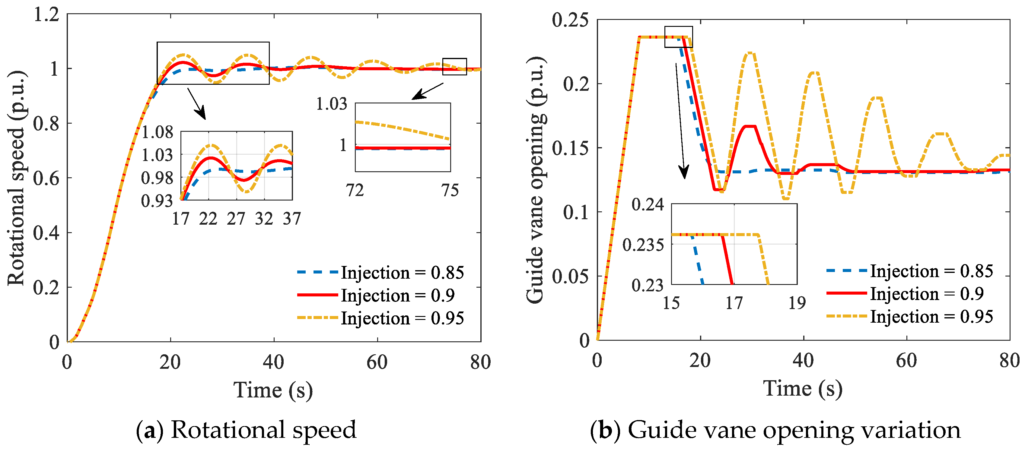
The two-stage scenario (open–close loop) is commonly adopted for the start-up process of pumped storage plants, and the PID pitching-in moment separates these two parts, which are usually associated with the rated rotational speed of the unit [40]. To explore the impact of the injection point on the transient process, three pitching-in moments correlate with injection points 0.85, 0.9, and 0.95 of rated rotational speed, and are executed under three typical start-up processes. The indices of overshoot and entry time of the controller are listed in Table 1. For brevity, only the transient processes of rotational speed and variation of the guide vane opening regarding the two-unit simultaneous start-up conditions are presented in Figure 5.
The simulation results in Figure 5 and Table 1 show that the injection point has a noticeable effect on the transient process of the start-up conditions. More specifically, increasing the injection point gives rise to longer operation time during open loop stage, and the PID entry time is therefore lagged. When the inflection point is increased from 0.85 to 0.95, the entry time is delayed from 15.09 s to 17.49 s. Meanwhile, the rotational speed overshoot has inevitably increased by 4.94%, solely altering the inflection point. Furthermore, another phenomenon worth noting is that, when injection point equals 0.95, the units fail to reach a stable state in the limited simulation time although the opening of guide vane is kept in adjustment. In addition, the reciprocating opening and closing of guide vane will inevitably bring water hammer pressure fluctuations, which greatly affect the rapid grid connecting and threatening the safe and stable operation of power plants. From Figure 5a, there exists a static error in all three injection point simulations. Though the static error is caused by improper PID parameter setting, the inflection point also affects the static error to a certain extent.

3.2. Effects of the Start-Up Interval Time

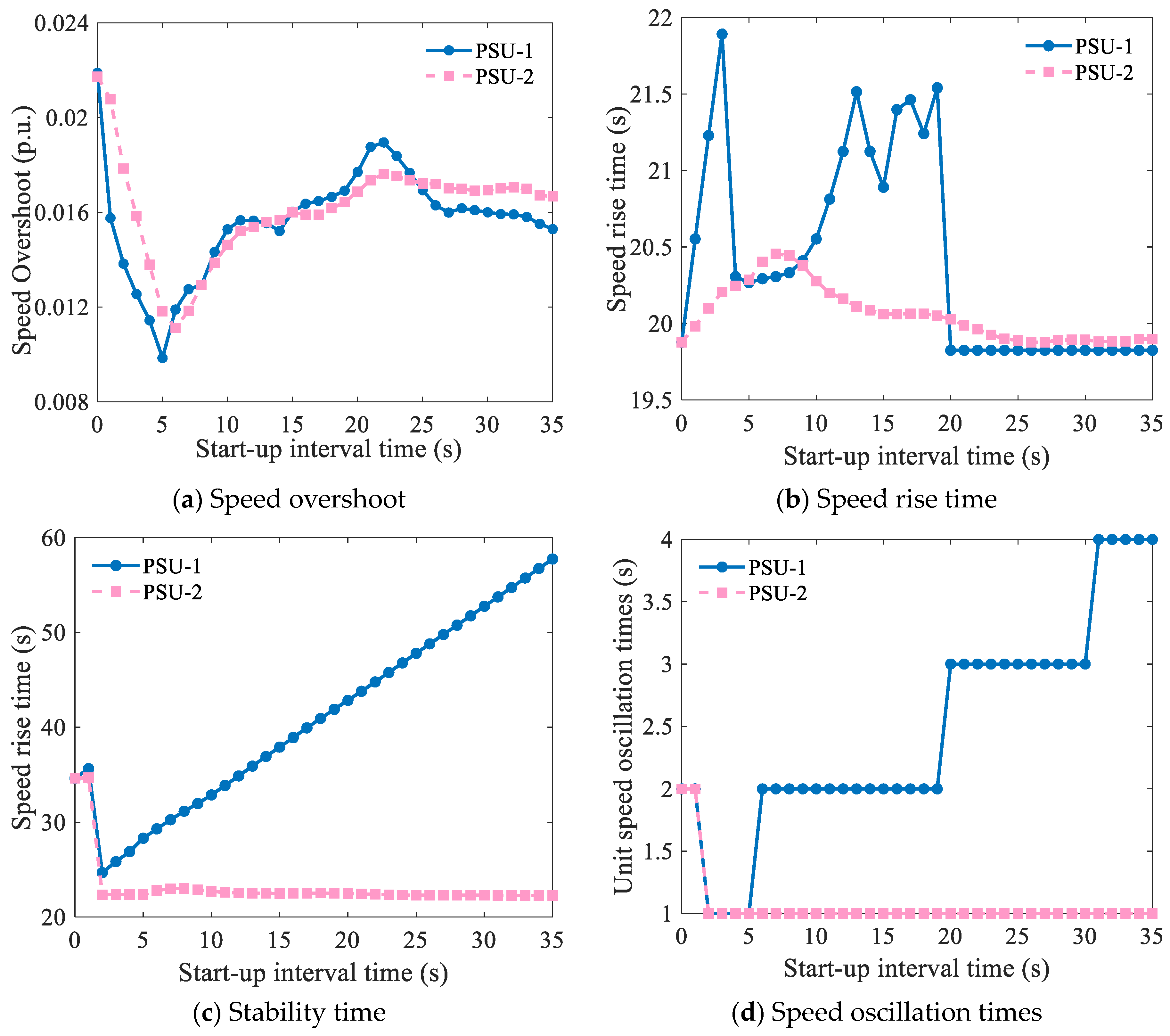
For the arrangement of annular pipeline structure, there exists prominent hydraulic interference between shared units. This means that when one unit suddenly changes working conditions, the transient process performance of the other will be notably affected. Meanwhile, the load fluctuation of the power grid is unanticipated, which makes it possible for the correlative units to be activated simultaneously or successively at intervals. In order to investigate the influence of start-up interval time  Δ t  on the transient process performance, emulations under different  Δ t  are conducted, and the corresponding transient performance of the prior and rear units, i.e., speed overshoot, speed rise time, stability time, and speed oscillation times, is extracted in Figure 6. During the analysis, only start-up interval time is varied within [0, 35]; other parameters are maintained at their default settings.
It can be concluded that the start-up performances are significantly altered by varying start-up interval time, and the first-started unit PSU-1 is more sensitive to the start-up interval time. In particular, the speed overshoot reaches its maximum for both units when the start-up interval time is 0 and decreases to the comparatively optimal value at  Δ t = 5 s . Then, the indicator gradually increases until it achieves relative maximal value at  Δ t = 22 s . Regarding speed rise time, stability time, and speed oscillation times, the effect of start-up interval time exerts influence mainly on the prior unit. The speed rise time has no obvious pattern and the value changes significantly before the start-up interval time exceeds 20 s. The second index of the PSU-1 increases linearly together with start-up interval time; the speed oscillation times also grow with the increase of interval time. Affected by the hydraulic interference from the rear, the prior unit fails to achieve a stable state until the other unit is stabilized as well. However, for the rear started unit, these three measures were little changed, with a maximum fluctuation range of 0.6 s and 3.5 s, respectively. Though start-up interval time may have beneficial effects on transient process performance under certain circumstances, since more attention is paid to the worst scenario, the worst start-up interval time is defined as  Δ t = 22 s .

3.3. Effects of the Water Head

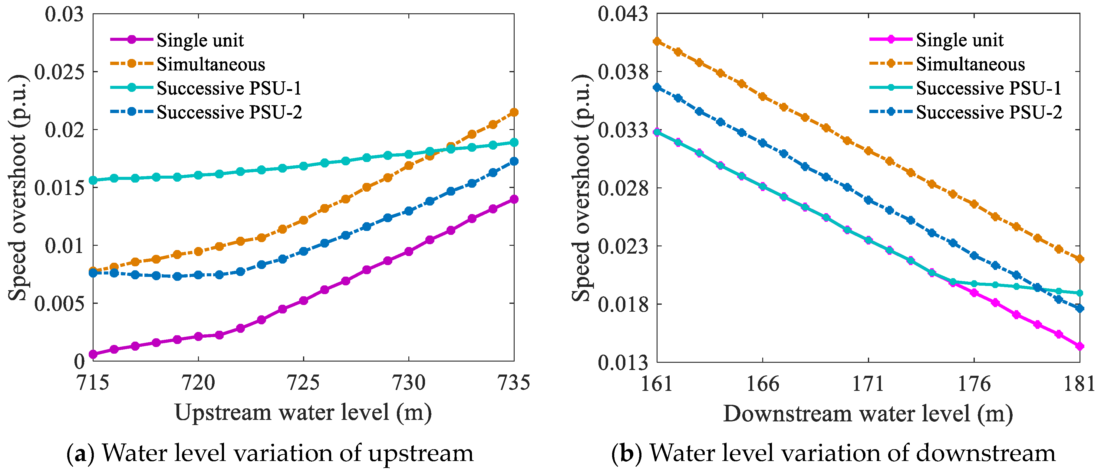
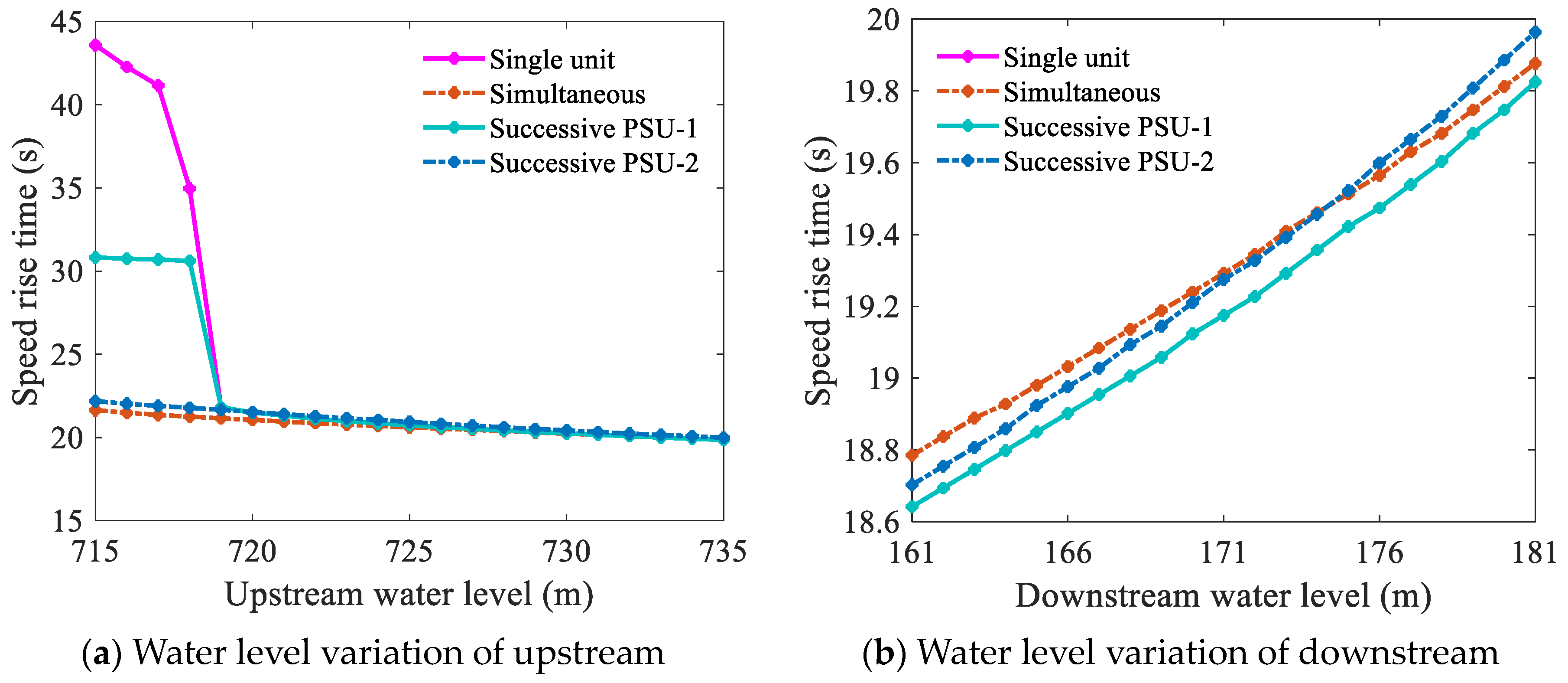
The water head can be roughly determined by the difference between the upstream and downstream water levels. To demonstrate the impact of the water head on start-up processes and find out the worst working head, different water levels regarding upstream and downstream are selected under three typical start-up conditions. The intervals of upper and lower water levels selected are different combinations of water levels used in daily operation. For successive start-up processes, the worst start-up interval times are selected. Similarly, other parameters of the PSHS are constant, and two independent simulations are conducted. The water level ranges of reservoirs are set as [715, 735] and [161, 181] for upstream and downstream, respectively. The corresponding speed overshoot and speed rise time under water level variations of upstream and downstream are extracted in Figure 7 and Figure 8.
It is evident from Figure 7 that both upper and lower reservoir water levels demonstrate an approximately linear relationship with speed overshoot regardless of the start-up conditions, while opposite effects exist when increasing the water level. Specifically, increasing the upper level leads to a deterioration in overshoot, resulting in the improvement for the lower. In terms of gross head variation, the growth will deploy more potential energy acting on the runner and bring about harmful impact in the form of higher overshoot. Therefore, the worst working head combination can be determined with maximum upper level and minimum lower level, which will be adopted for the subsequent control optimization.
As can be seen from Figure 8, the upstream and downstream water levels also have a distinct impact on the unit’s rise time. The increase of the upper reservoir water level shortens the rise time, while the increase of the lower makes the rise time longer. To sum up, the higher upstream water level, the lower the downstream water level; that is, the higher the total working head, the shorter the speed rise time of the unit, which is conducive to the rapid start of the unit. However, at the same time, the speed overshoot increases. There is a contradictory relationship between overshoot and rise time. It is natural to think of converting the selection of optimal start-up strategy into multi-objective optimization problems.

4. Control Strategy and Coordinated Optimization

4.1. Variable Universe Fuzzy PID Controller

In industrial servo systems, the traditional PID controller has been widely used because of its simple structure and stable performance [41]. However, the control effect is barely satisfactory considering that the complexity of PID control parameter adjustment is greatly increased when the mathematical model is uncertain, and it is unwise to design a specific set of PID parameters for each start-up condition [42]. On the contrary, a fuzzy PID controller introduces fuzzy logic inference, in which control parameters are dynamically modulated by the fuzzy relation between increments and errors [43,44]. Meanwhile, the control accuracy cannot meet the control requirements, despite its strong robustness. Apart from that, since the scope of the fuzzy PID controller is commonly invariant, its accuracy is easily affected by the fuzzy domain. As the controlled process evolves, the error and error rate will gradually approach the vicinity of zero, which will inevitably lead to a reduction in control precision if the system continues to use the initial domain for fuzzy reasoning.
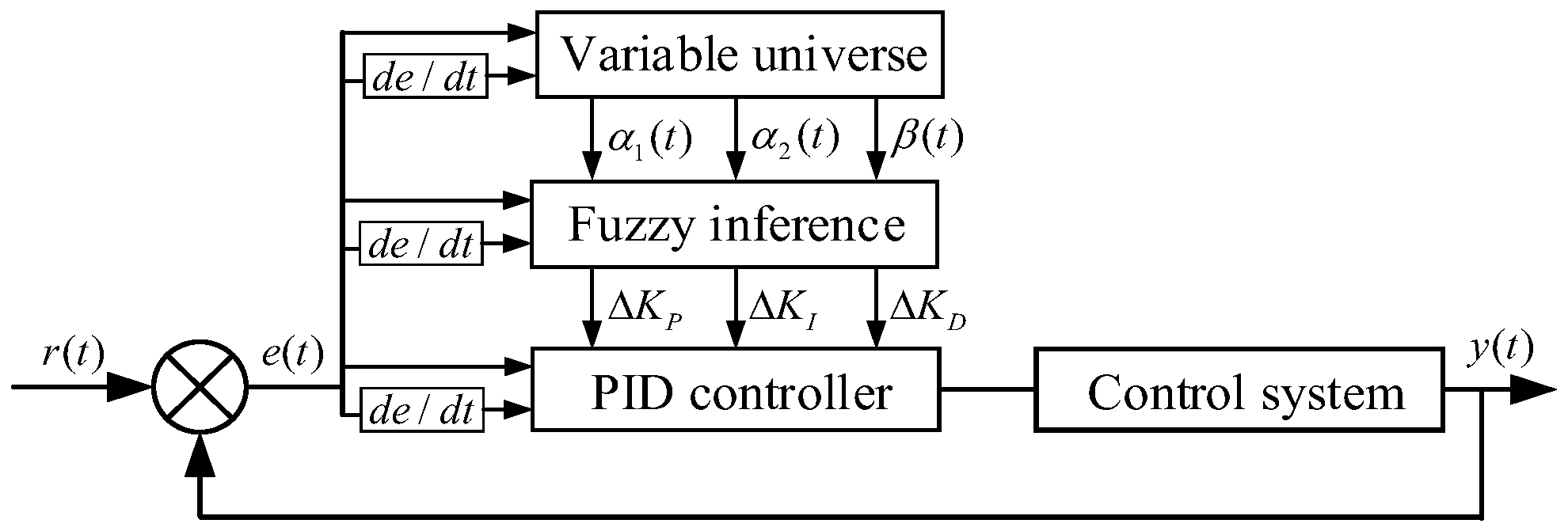
Aiming at the target of a unified paradigm of start-up processes characterized by high nonlinearity, strong coupling, and large time delay, a control strategy based on the variable universe fuzzy PID controller is designed, which combines the concept of variable universe with fuzzy PID to form a control system structure. The principle of variable universe and the controller block diagram are presented in Figure 9 and Figure 10, respectively. The designed controller consists of three sequential parts: the variable universe part is a fuzzy adjuster with error  e  and error rate  e c  for inputs and the stretch factors  α 1 , α 2 , β  for outputs, which focus on adjusting the fuzzy domain by adaptively changing stretch factors. Further, attention is paid to modification of PID parameters, and the parameter increments of the controller are calculated in the fuzzy inference part based on the fuzzy rules. On top of that, the modified PID controller adjusts the unit opening to achieve a smooth and fast start-up.
The key to a variable universe fuzzy controller is to determine the reasonable mechanisms of stretch factor and parameter increments, so that the final control effect can meet the requirements with maximum satisfaction. The fuzzy stretch factor laws are proposed to describe the change rule of fuzzy domains, as shown in Table 2 and Figure 11, which split into seven states for input and four fuzzy sets for output on account of expert experience in practice. To be more specific, seven states {NB, NM, NS, ZE, PS, PM, PB} equally divide the area of input, and the meaning of N, P, B, M, S, and ZE are Negative, Positive, Big, Medium, Small, and Zero, respectively. Regarding the four output fuzzy sets, {L, B, M, S} corresponding to peak points of [1, 0.75, 0.5, 0.25] are defined, respectively.
Accordingly, under the premise that the form of rule does not change, the universe expands as the error becomes small and vice versa. Assuming that the initial domains of input and output variables are  [ E , E ]  and  [ U , U ] , the domains in the real control process should be as follows:
E = [ α ( e , e c ) × E , α ( e , e c ) × E ] U = [ β ( e , e c ) × U , β ( e , e c ) × U ]
where  α  and  β  are stretch factors for input and output and  E  and  U  are the initial domain of input and output.  E  and  U  are the corresponding domains after change.
After determining the variable universe, the fuzzy PID is introduced. The same as the variable universe part, error  e  and the error rate  e c  are the inputs of the fuzzy inference engine. Based on the setting principle that the variation of PID control parameters is beneficial to system stability and control performance, the fuzzy control rules are established in accordance with the operational situation of the PSHS, which is presented in Table 3 and Figure 12. In the controlling process, the revised PID parameters can be dynamically obtained online according to the fuzzy inference rules. The triangle functions are taken as the membership function, the Mamdani law is adopted for fuzzy inference, and the area center of gravity method for defuzzification.
The variable universe fuzzy PID controller possesses good anti-interference ability, which can adjust the system parameters in real time according to the feedback information, consequently improving the system response speed and robustness. The joint effects of the variable universe and fuzzy theory help realize the adaptive operation conditions through magnifying or reducing the domain properly.

4.2. Coordinated Optimization of Start-Up Strategy

In consideration of regulation performance, the unit speed and hydraulic pressure are two main concerns, while the change in water pressure is relatively moderate in terms of the start-up process. Plenty of work has been dedicated to unit speed optimization concerning both quickness and stability. However, most of the literature focuses on certain optimization stages of the start-up strategy and tries to achieve satisfactory results for a particular condition, like successive or simultaneous start-up processes. In practice, however, there always exists an evolutionary relationship between different conditions, which is subjected to unpredictable load changes or disturbance. Here, we coordinate two start-up stages and specify the unified paradigm applicable to multiple start-up conditions.

4.2.1. Optimization Objectives and Decision Variables

In the case of stationarity of rotational speed, the overshoot of rotational speed indicates that robust stability is specified as an objective but might lead to a tedious and sluggish control process by merely considering a single goal. The speed rise time, describing the duration from the start-up until the rated speed moment, is particularly suited for the rapidity objective. It has to be mentioned that, for successive start-up conditions, the regulation performance of the prior start-up unit is obviously distinct from the rear one, and the control qualities of both ought to be considered as included in optimization.
min F 1 = Δ n Sing + Δ n Simu + Δ n 1 Succ + Δ n 2 Succ min F 2 = t s Sing + t s Simu + t s 1 Succ + t s 2 Succ
where  F 1 , F 2  are objective functions that need to be optimized,  Δ n  and  t  are variation of rotational speed and speed rise time, and superscript Sing, Simu, and Succ are three working conditions, i.e., single unit start-up, simultaneous start-up, and successive start-up condition.
The first objective function tries to reduce the fluctuation degree of rotational speed and the second tries to ensure good tracking ability to a desired set-point. A terrible regulation performance is characterized by the presence of higher values and vice versa; both must be minimized for effective and smooth grid connection.  D V  indicates decision variables, the operational parameters of open-loop, i.e., maximum starting opening are shown as  y c , and the initial parameters of close-loop controller, i.e., initial proportional  K P , integral  K I , and derivative gains  K D , are selected as decision variables. In addition, based on the results in Section 3, the injection point  θ  is likewise adopted as decision variable. The maximum working head and worst successive start-up interval time are taken as the worst start-up conditions.
D V = [ y c , K P , K I , K D , θ ]

4.2.2. Optimization Constraints

To ensure that the start-up strategy can be applied to actual situations, constraints including the boundary of decision variable and requirements of regulation guarantee calculation must be set prior to the multi-objective optimization, which are listed in Table 4.

4.2.3. Optimization Procedure

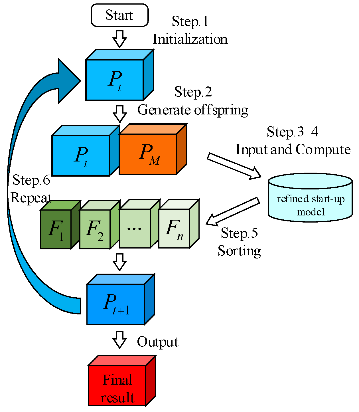
Handling objectives on the quickness and control quality of the start-up process is equally important and challenging, especially since the control objectives of the two are likely to contradict with each other. The elite non-dominated sorting genetic algorithm (NSGA-II) [45], due to its effective parallel search properties and efficient non-dominance ranking mechanism, is widely used in engineering practice, and is also adopted in this paper to solve the unified paradigm problem. The optimization flow chart is shown in Figure 13.
Step 1: set the basic parameters of algorithm and initialize population.
Step 2: conduct tournament selection, crossover recombination, and polynomial variation on parent population to generate offspring population.
Step 3: input operation strategy parameters into refined start-up model, calculate the transient process under single-unit start-up condition, simultaneous start-up condition, and successive start-up condition, respectively.
Step 4: compute the optimization objectives by extracting the overshoot of rotational speed and the speed rise time under each start-up condition.
Step 5: execute non-dominated sorting on the individual, and then the offspring population is combined with the parent to undergo an elitism selection.
Step 6: repeat Step 2–5 until the stop criterion is reached. Then, the population in the elite archive collection is output as final result.

5. Numerical Experiments and Analysis

To verify the effectiveness of the proposed operational unified paradigm, the mathematical models of PSU with integrated start-up strategy and coordinated optimization are simulated in MATLAB. According to the results in Section 3.2 and Section 3.3, the worst start-up interval time and worst working water head are assigned to the start-up conditions. The operating parameters of pumped storage plants are shown in Table 5, and basic parameters of the algorithm using the most common combination is listed in Table 6.

5.1. Comparative Analysis of Control Strategy Performance

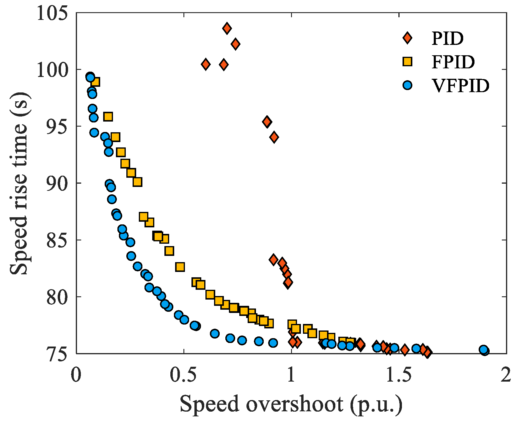
In order to verify the superiority of the proposed strategy, the variable universe fuzzy PID, together with traditional PID and fuzzy PID controllers, is employed and put into an optimization procedure. For a fair comparison, the decision variables and boundaries for three controllers are allotted to the same circumstances, and Pareto fronts optimized by NSGA-II are shown in Figure 14. Table 7 shows the individuals under three operational strategies.
It is apparent that the candidate schemes of the variable universe fuzzy PID controller dominate their counterparts, the other two controllers, which reveals that the variable universe fuzzy PID controller has better regulation performance for start-up operation of pumped storage plants, especially in regard to overshoot and speed rise time. Through the introduction of fuzzy theory, the relatively inferior results acquired by fuzzy PID possess good adaptability in working conditions compared with the PID controller. The potential limitation of fuzzy PID lies in the invariant universe, which will result in a mismatch between the control range and control process within the control corridor when both error and error rate are small. On this basis, via the integration of variable universe and fuzzy inference, the proposed strategy has desirable advantages for the improvement of the dynamic quality and further improves condition adaptability. Apart from that, a broader distribution with promising tradeoffs between objectives can be achieved, as presented in Figure 14, providing more alternative choices for maintenance personnel according to requirements for security. It is important to point out that the control accuracy is effectively improved in the late control period, although these contents are not reflected in the numerical value of the optimization objectives. All these results help to realize the smooth and rapid installation of pumped storage plants into power grid, regardless of start-up conditions.
As clearly seen in Table 7, individuals solved by NSGA-II are ranked from small to large according to the speed overshoot target. With the increase of the speed overshoot, the rise time gradually decreases, which further verifies that rapidity and stability are a pair of contradictory objectives during the start-up transient process. The candidate schemes of VFPID controller are obviously superior to the other two controllers. The minimum speed overshoot obtained by the PID controller is 0.6016, and while it can be reduced to 0.088 and 0.0642 under the FPID and VFPID controllers, the performance gets improved by an order of magnitude. On the basis of individual sets, the optimal operation schemes under three control strategies are specified by the ideal point nearest to the method. The transient processes of the successive start-up conditions are depicted in Figure 15.
In the successive start-up conditions, two units controlled by PID have a large overshoot in the transient process, of 17.04% and 18.54%, respectively. FPID improves this dilemma, and the overshoot is reduced by 9.38% and 10.03%, respectively. Among the three control strategies, the optimal speed overshoot is obtained by VFPID, which is only 4.72% and 4.92%. Under the condition of PID and FPID playing roles, the start-up processes of the unit experienced several fluctuations, and the PID controller speed fluctuation attenuation was slow, which made the unit unable to be connected to the grid as scheduled. At the simulation stage of 25~40 s, the second unit starts to open its guide vane after the worst successive start-up interval. Although PSU-1 is affected by the hydraulic interference, the VFPID quickly absorbed this part of impact, making the transient process of PSU-1 smoothly restore to the rated speed, while PID and FPID controllers caused the unit to stick in a fluctuating state. The above phenomenon can be attributed to the control parameter invariance and fuzzy domain invariance defects of the PID controller and FPID controller, resulting in a mismatch between control range and control process. By introducing variable domain ideology and fuzzy control logic, the proposed VFPID controller has better regulating performance and operating condition adaptability for the start-up process of pumped storage plants, especially in regard to restraining speed overshoot and hydraulic interference. This offers more ideal advantages for improving control quality and maintaining the security of power systems.

5.2. Effectiveness Analysis of Collaborative Operation and Collaborative Optimization

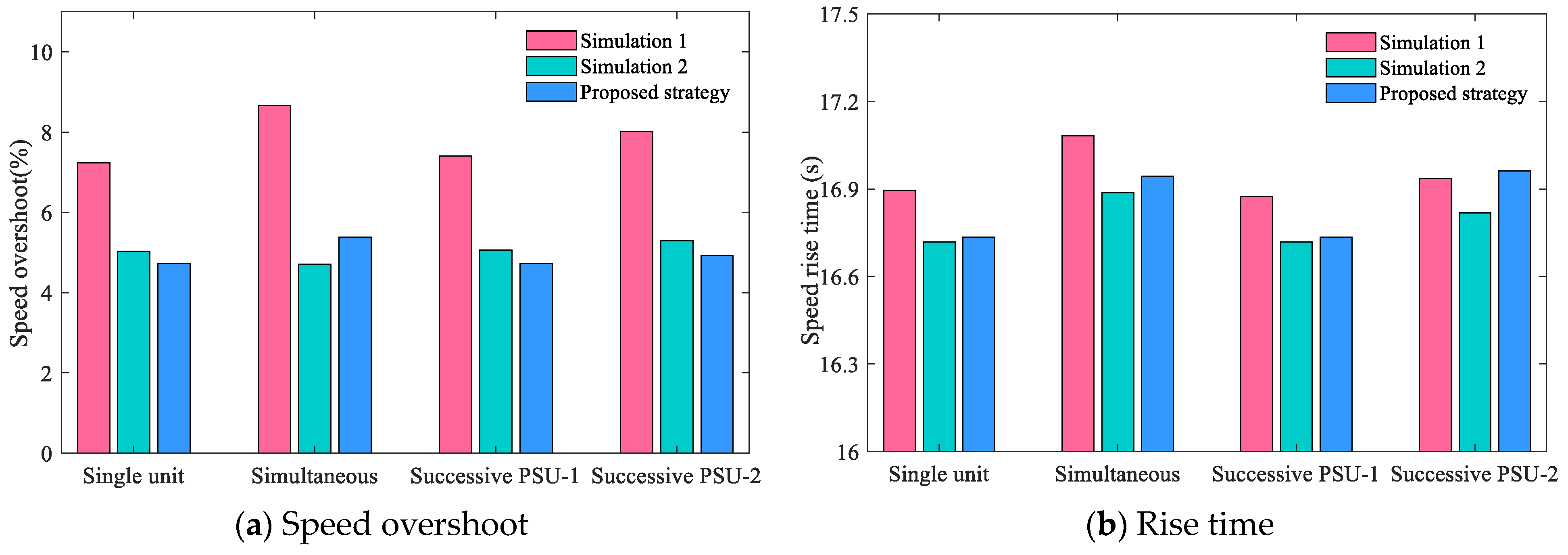
This section further studies the effectiveness of open–close loop collaborative operation and multi-condition collaborative optimization. Two groups of comparison tests are set as follows. Simulation 1 keeps fixed open-loop parameters, and only close-loop parameters of VFPID are optimized under three typical start-up conditions to verify the advantage of collaborative operation. In the open-loop part, the injection points are  θ = 0.9  and  y c = 0.275 . In Simulation 2, open–close loop parameters are optimized only in simultaneous start-up conditions, so as to verify the necessity of collaborative optimization under multiple operating conditions. After optimization by NSGA-2 and selection by choosing the ideal point nearest the method, the optimal control parameters and indicators are shown in Table 8 and Figure 16.
As can be seen from Figure 16, in Simulation 1, which only considers close-loop optimization, three typical start-up conditions are included in the objective function and the VFPID controller is adopted in the close-loop, but the speed overshoot and rise time obtained are worse than the collaborative optimization open–close loop control strategy. To be more specific, the speed overshoot and rise time are 8.66% and 17.08 s, respectively, which is higher than the other two experiments in open–close loop optimization. It can be noted that the open–close loop collaborative optimization has five adjustable parameters, while Simulation 1 only has three close-loop adjustable parameters for optimization. The increase in the dimension concerning decision variables obviously improves the search scope of the optimal control law. In addition, the maximum opening of open-loop part  y c  and the controller injection point  θ  have a significant influence on the start-up transient process. Unreasonable opening and injection point will also deteriorate the dynamic quality. The open-loop and close-loop collaborative optimization not only improves the rapidity in the open-loop part, but it also takes the two parts into consideration cooperatively, which achieves a balance between rapidity and stationarity, thus obtaining excellent control indexes.
Simulation 2 acquire the best indices under simultaneous start-up conditions of the three experiments: the speed overshoot is 4.71%, lower than that in Simulation 1 (8.66%) and the proposed strategy (5.38%). In terms of the rotational speed rising time, it is also less than that of the multi-condition collaborative optimization strategy. While in single-unit start-up and successive start-up conditions, the speed overshoot of Simulation 2 is higher than that of the proposed strategy. Taking multi-conditions and open–close loop stages into account when specifying optimal start-up strategy can avoid the occurrence of special situations such as the optimal transient process in a single working condition does not meet the requirements adjustment qualityin other working conditions. Moreover, it also avoids the adverse effects on the unit or even the power station caused by the mismatch between the control parameters and the working conditions.

5.3. Robustness Analysis of the Unified Paradigm

The preceding analysis is conducted under the premise of worst working condition combinations, which verified the robustness of the proposed unified paradigm regarding working conditions. In a more realistic situation, for the existence of mechanical wear-and-tear and conduction delay, the fact that the operational process might not be performed strictly according to the given trajectory greatly necessitates robustness analysis of the policy parameters. In addition, the unit may be disturbed by frequency interference; whether the controller can respond quickly and suppress the speed fluctuation also calls for further investigation.
Here, six different simulations on operational parameter variation are conducted separately. For simplicity, the dynamic quality of the proposed unified paradigm is taken as benchmark N0. N1, N2 are set under the most unfavorable working water head but different successive start-up interval times; the working water head of N3 and N4 changes under the worst successive startup interval; N5 and N6 indicate that control parameters and interval time change under medium and low head conditions, respectively. Table 9 lists the above working conditions and control parameters. “-” indicates that the working conditions do not change with respect to N0.
The comparison conditions above fully verify the robustness performance of the proposed control strategy on the dynamic quality of the start-up transient processes from the aspects of working head change, interval time change, and controller parameter change. Regarding the results shown in Table 10, “/” means no change happens relative to the working condition N0, “↑” and “↓” mean the quality of index increases or decreases, respectively, namely deterioration or improvement.
As can be seen from Table 10, the optimized startup control strategy takes the speed overshoot and speed rise time in the startup transition process in a balanced manner and achieves satisfactory dynamic quality under various changing conditions. To be specific, the control strategy is optimized under the worst successive interval time and working water head of N0 working conditions. The speed overshoots of PSU-1 and PSU-2 in N1 and N2 working conditions, only changing the interval time, are better than that of N0. Compared with N2 to N0, the overshoot of PSU-1 is improved by 1.16%, which only makes the speed rising time lag by 0.376 s. For PSU-2, the unit overshoot is reduced by 0.05% at the expense of the 0.049 s rising time, and the dynamic quality of start-up condition is almost unchanged. N3 is the downstream highest water level condition. Compared with N0, the rotational speed overshoot decreases by 1.43% and 0.93%, respectively, in the single-unit start-up and PSU-2 under successive start-up conditions. Although the overshoot of PSU-1 in successive start-up conditions gets worse, it only increases by 0.52% at the maximum, and the variation range of rise time is within 1 s. The same conclusion can be reached by comparing N4 and N0 in the upstream lowest water head condition, that is, the proposed control strategy can also exert excellent control performance in the low water head conditions. Under the condition that interval time, upstream and downstream water level, and control parameters are changed in N5 and N6 operating conditions, the unit’s rise time lags by 1.365 s at most, and the overshoot deteriorates by 0.2%. The reason it works out so well lies in the fuzzy strategy contained in the proposed startup strategy, and the adaptability of the control strategy is greatly improved through the integration of fuzzy control. At the same time, a variable universe is introduced to further improve the control precision of the controller. In particular, the unit speed overshoot is generally improved under other design conditions, only at the cost of a slight lag in the speed rise time. On the one hand, it is beneficial to optimize the control strategy based on the most unfavorable head and the worst successive startup interval time. On the other hand, it also verifies that the proposed open–close loop collaborative fuzzy startup control strategy has extremely high operating condition adaptability and control robustness.

6. Conclusions

With the growing penetration of variable renewable energy resources, it is harder to maintain the balance between grid load and power generation, which is a very important albeit challenging task in cracking the quick start and grid connection of pumped storage units. This research proposed a more comprehensive and coordinated start-up strategy to deal with this puzzle. Firstly, regarding the merits of representing precisely the hydraulic interference and dynamic behaviors, the refined start-up model of pumped storage plants is constructed by cascading pipeline, pumped storage turbine, generator, and governor systems. The effects of the operational parameters on typical start-up processes are enunciated explicitly, and the worst combinations of start-up parameters are located for the following study. The unified paradigm of start-up conditions is thereupon proposed, incorporating a variable universe fuzzy PID controller and collaborative optimization. The merit of the unified paradigm is in collaborative optimization of control strategy and an operation scheme for multiple working conditions. To verify the effectiveness of the proposed unified paradigm, comparisons are made among PID, fuzzy PID, and variable universe fuzzy PID controllers; the advantages of collaborative optimization involving open–close stages and multi-condition states are further verified by comparative analysis. The following conclusions can be drawn: (1) the proposed variable universe fuzzy PID controller has better control performance in the form of faster response, small overshoot, and better tracking performance. (2) The superiority of the unified paradigm is more obvious due to the comprehensive consideration of multiple start-up conditions. (3) By reducing the influence of the object on the control effect, error-free control is realized.
Furthermore, in this study, there are still more deficiencies that await further study. For more complex structural arrangements like super-long diversion tunnels or sloping ceiling tailrace tunnels, the transient process regarding start-up conditions might be more complicated. Moreover, the pressure pulsation during start-up process can also be selected as optimization target, providing a comprehensive reference for decision-makers.

Author Contributions

Conceptualization, B.L. and M.L.; Methodology, B.L.; Software, B.L.; Validation, B.L., M.L. and J.L.; Formal analysis, B.L.; investigation, B.L.; data curation, M.L. and J.L.; Writing—original draft preparation, B.L.; writing—review and editing, Y.Y. and J.L.; Visualization, B.L. and M.L.; supervision, J.L.; Project administration, Y.Y.; Funding acquisition, Y.Y. All authors have read and agreed to the published version of the manuscript.

Funding

This research was funded by National Key Research and Development Program of China [Grant No. 2023YFC3209501] and the Fundamental Research Funds for Central Public Welfare ResearchInstitutes (Grant No. CKSF2023313/HL, Grant No. CKSF2023293/HL).

Data Availability Statement

Original material presented in the research is included in the article.

Conflicts of Interest

Author Mengyao Li is employed by Power China Huadong Engineering Corporation Limited. The authors declare that they have no known competing financial interests or personal relationships that could have appeared to influence the work reported in this paper.

Nomenclature

Q Unit flow, (m3/s) E Initial domain of input, p.u.
t Time, (s) U Initial domain of output, p.u.
g Gravitational acceleration, (m/s2) Δ n Sing Overshoot of rotational speed under
A Equivalent pipe area, (m2)single-unit start-up condition, p.u.
H Hydrodynamic pressure, (m) Δ n Simu Overshoot of rotational speed under
L Length of pipe, (m)simultaneous start-up condition, p.u.
f Darcy–Weisbach resistance coefficient, p.u. Δ n 1 S u c c Overshoot of rotational speed of prior
D Diameter of pipe line, (m)unit under successive start-up condition, p.u.
c Celerity of water hammer wave, (m/s2) Δ n 2 Succ Overshoot of rotational speed of rear unit
x Relative value of water flow angle, p.u.under successive start-up condition, p.u.
y Relative value of guide vane opening, p.u. t r Sing Speed rise time under single-unit
h Relative value of water head, p.u.start-up condition, (s)
n Relative value of rotational speed, p.u. t r Simu Speed rise time under simultaneous
q Relative value of water flow, p.u.start-up condition, (s)
m Relative value of unit torque, p.u. t r 1 Succ Speed rise time of prior unit under
C y , C h , k 1 , k 2 Coefficients of transformation, p.u.successive start-up condition, (s)
α 1 Stretch factor for error, p.u. t r 2 Succ Speed rise time of rear unit under
α 2 Stretch factor for error rate, p.u.successive start-up condition, (s)
β Stretch factor for output, p.u. y a Ascending turning point, p.u.
J Moment of inertia, (ton/m2) n d Rotational speed of descent moment, p.u.
M t Shaft mechanical moment, p.u. y d Descending turning point, p.u.
y c Guide vane rising fixed point, p.u. K P 0 Initial proportional gain, p.u.
Δ K P Incremental of proportion, p.u. K I 0 Initial integral gain, p.u.
Δ K I Incremental of integral, p.u. K D 0 Initial derivative gain, p.u.
Δ K D Incremental of derivative, p.u. θ Injection point, p.u.
Δ t Start-up interval time, s

References

  1. Hermans, M.; Bruninx, K.; Delarue, E. Impact of generator start-up lead times on short-term scheduling with high shares of renewables. Appl. Energy 2020, 268, 114935. [Google Scholar] [CrossRef]
  2. Bhattacharya, M.; Paramati, S.R.; Ozturk, I.; Bhattacharya, S. The effect of renewable energy consumption on economic growth: Evidence from top 38 countries. Appl. Energy Barking Then Oxf. 2016, 162, 733–741. [Google Scholar] [CrossRef]
  3. Yan, R.; Lu, Z.; Wang, J.; Chen, H.; Wang, J.; Yang, Y.; Huang, D. Stochastic multi-scenario optimization for a hybrid combined cooling, heating and power system considering multi-criteria. Energy Convers. Manag. 2021, 233, 113911. [Google Scholar] [CrossRef]
  4. Solaun, K.; Cerda, E. Impacts of climate change on wind energy power—Four wind farms in Spain. Renew. Energy 2020, 145, 1306–1316. [Google Scholar] [CrossRef]
  5. Nguyen, H.T.; Felder, F.A. Generation expansion planning with renewable energy credit markets: A bilevel programming approach—ScienceDirect. Appl. Energy 2020, 276, 115472. [Google Scholar] [CrossRef]
  6. Dai, K.; Bergot, A.; Liang, C.; Xiang, W.; Huang, Z. Environmental issues associated with wind energy—A review. Renew. Energy 2015, 75, 911–921. [Google Scholar] [CrossRef]
  7. Wan, B.; Tian, L.; Fu, M.; Zhang, G. Green development growth momentum under carbon neutrality scenario. J. Clean. Prod. 2021, 316, 128327. [Google Scholar] [CrossRef]
  8. Chen, J.J.; Zhao, Y.L.; Peng, K.; Wu, P.Z. Optimal trade-off planning for wind-solar power day-ahead scheduling under uncertainties. Energy 2017, 141 Pt 2, 1969–1981. [Google Scholar] [CrossRef]
  9. Ren, G.R.; Wan, J.; Liu, J.; Yu, D.; Soder, L. Analysis of wind power intermittency based on historical wind power data. Energy 2018, 150, 482–492. [Google Scholar] [CrossRef]
  10. Faridnia, N.; Habibi, D.; Lachowicz, S.; Kavousifard, A. Optimal scheduling in a microgrid with a tidal generation. Energy 2019, 171, 435–443. [Google Scholar] [CrossRef]
  11. Kousksou, T.; Bruel, P.; Jamil, A.; Rhafiki, T.E.; Zeraouli, Y. Energy storage: Applications and challenges. Sol. Energy Mater. Sol. Cells 2014, 120, 59–80. [Google Scholar] [CrossRef]
  12. Hou, H.; Xu, T.; Wu, X.; Wang, H.; Tang, A.; Chen, Y. Optimal capacity configuration of the wind-photovoltaic-storage hybrid power system based on gravity energy storage system. Appl. Energy 2020, 271, 115052. [Google Scholar] [CrossRef]
  13. Ning, L.; Chow, J.H.; Desrochers, A.A. Pumped-storage hydro-turbine bidding strategies in a competitive electricity market. IEEE Trans. Power Syst. 2004, 19, 834–841. [Google Scholar]
  14. Zhang, Y.; Zheng, X.; Li, J.; Du, X. Experimental study on the vibrational performance and its physical origins of a prototype reversible pump turbine in the pumped hydro energy storage power station. Renew. Energy 2018, 130, 667–676. [Google Scholar] [CrossRef]
  15. Liu, D.; Li, C.; Malik, O.P. Operational characteristics and parameter sensitivity analysis of hydropower unit damping under ultra-low frequency oscillations. Int. J. Electr. Power Energy Syst. 2022, 136, 107689. [Google Scholar] [CrossRef]
  16. Chazarra, M.; Pérez-Díaz, J.I.; García-González, J. Deriving Optimal End of Day Storage for Pumped-Storage Power Plants in the Joint Energy and Reserve Day-Ahead Scheduling. Energies 2017, 10, 813. [Google Scholar] [CrossRef]
  17. Li, H.; Zheng, H.; Zhou, B.; Li, G.; Yang, B.; Hu, B.; Ma, M. Two-Part Tariff of Pumped Storage Power Plants for Wind Power Accommodation. Sustainability 2022, 14, 5603. [Google Scholar] [CrossRef]
  18. Xu, Y.H.; Zhao, K.J.; Qian, Z.D.; Zhou, J.; Wu, X. Design of three-stage start-up optimal strategy based on fuzzy fractional-order proportion integration differentiation controller of pumped storage unit under low water head. J. Energy Storage 2022, 50, 104315. [Google Scholar] [CrossRef]
  19. Wang, Z.; Li, C.; Lai, X.; Zhang, N.; Xu, Y.; Hou, J. An Integrated Start-Up Method for Pumped Storage Units Based on a Novel Artificial Sheep Algorithm. Energies 2018, 11, 151. [Google Scholar] [CrossRef]
  20. Chen, D.; Zhang, M.; Zhang, C.; Yang, M.; Mao, C.; Shen, C. Research on hydraulic–electric interference and optimisation of multi-turbine hydropower system based on the dual control mode. IET Renew. Power Gener. 2019, 13, 1096–1104. [Google Scholar]
  21. Zheng, Y.; Chen, Q.; Yan, D.; Zhang, H. Equivalent circuit modelling of large hydropower plants with complex tailrace system for ultra-low frequency oscillation analysis. Appl. Math. Model. 2021, 103, 176–194. [Google Scholar] [CrossRef]
  22. Liu, B.; Zhou, J.; Xu, Y.; Lai, X.; Shi, Y.; Li, M. An optimization decision-making framework for the optimal operation strategy of pumped storage hydropower system under extreme conditions. Renew. Energy 2021, 182, 254–273. [Google Scholar] [CrossRef]
  23. Zhang, H.; Chen, D.; Xu, B.; Patelli, E.; Tolo, S. Dynamic analysis of a pumped-storage hydropower plant with random power load. Mech. Syst. Signal Process. 2018, 100, 524–533. [Google Scholar] [CrossRef]
  24. Hu, J.; Yang, J.; Zeng, W.; Yang, J. Hydraulic interaction of two parallel pump-turbines in constant-speed oscillation: Measurement, simulation, and sensitivity analysis. Renew. Energy 2021, 176, 269–279. [Google Scholar] [CrossRef]
  25. Zhang, H.; Guo, P.; Sun, L. Transient analysis of a multi-unit pumped storage system during load rejection process. Renew. Energy 2020, 152, 34–43. [Google Scholar] [CrossRef]
  26. Zuo, Z.; Fan, H.; Liu, S.; Wu, L. S-shaped characteristics on the performance curves of pump-turbines in turbine mode—A review. Renew. Sustain. Energy Rev. 2016, 60, 836–851. [Google Scholar] [CrossRef]
  27. Xu, B.; Chen, D.; Venkateshkumar, M.; Xiao, Y.; Yue, Y.; Xing, Y.; Li, P. Modeling a pumped storage hydropower integrated to a hybrid power system with solar-wind power and its stability analysis. Appl. Energy 2019, 248, 446–462. [Google Scholar] [CrossRef]
  28. Badur, J.; Bryk, M. Accelerated start-up of the steam turbine by means of controlled cooling steam injection. Energy 2019, 173, 1242–1255. [Google Scholar] [CrossRef]
  29. Hou, J.; Li, C.; Tian, Z.; Xu, Y.; Lai, X.; Zhang, N.; Zheng, T.; Wu, W. Multi-Objective Optimization of Start-up Strategy for Pumped Storage Units. Energies 2018, 11, 1141. [Google Scholar] [CrossRef]
  30. Li, Y.; Hou, J.; Gu, J.; Li, C.; Xu, Y. Dynamic Characteristics and Successive Start-Up Control Strategy Optimization of Pumped Storage Units under Low-Head Extreme Conditions. Energies 2022, 15, 5428. [Google Scholar] [CrossRef]
  31. Xu, Y.; Zheng, Y.; Du, Y.; Yang, W.; Peng, X.; Li, C. Adaptive condition predictive-fuzzy PID optimal control of start-up process for pumped storage unit at low head area. Energy Convers. Manag. 2018, 177, 592–604. [Google Scholar] [CrossRef]
  32. Lei, L.; Li, F.; Kheav, K.; Jiang, W.; Luo, X.; Patelli, E.; Xu, B.; Chen, D. A start-up optimization strategy of a hydroelectric generating system: From a symmetrical structure to asymmetric structure on diversion pipes. Renew. Energy 2021, 180, 1148–1165. [Google Scholar] [CrossRef]
  33. Guo, W.; Xu, X. Sliding mode control of regulating system of pumped storage power station considering nonlinear pump-turbine characteristics. J. Energy Storage 2022, 52, 105071. [Google Scholar] [CrossRef]
  34. Zhao, Z.; Yang, J.; Chung, C.Y.; Yang, W.; He, X.; Chen, M. Performance enhancement of pumped storage units for system frequency support based on a novel small signal model. Energy 2021, 234, 121207. [Google Scholar] [CrossRef]
  35. Lai, X.; Li, C.; Zhou, J.; Zhang, Y.; Li, Y. A multi-objective optimization strategy for the optimal control scheme of pumped hydropower systems under successive load rejections. Appl. Energy 2020, 261, 114474. [Google Scholar] [CrossRef]
  36. Li, D.; Wang, H.; Qin, Y.; Wei, X.; Qin, D. Numerical simulation of hysteresis characteristic in the hump region of a pump-turbine model. Renew. Energy 2017, 115, 433–447. [Google Scholar] [CrossRef]
  37. Huang, W.; Yang, K.; Guo, X.; Ma, J.; Wang, J.; Li, J. Prediction Method for the Complete Characteristic Curves of a Francis Pump-Turbine. Water 2018, 10, 205. [Google Scholar] [CrossRef]
  38. Rezghi, A.; Riasi, A. Sensitivity analysis of transient flow of two parallel pump-turbines operating at runaway. Renew. Energy 2016, 86, 611–622. [Google Scholar] [CrossRef]
  39. Zheng, Y.; Chen, Q.; Yan, D.; Liu, W. A two-stage numerical simulation framework for pumped-storage energy system. Energy Convers. Manag. 2020, 210, 112676. [Google Scholar] [CrossRef]
  40. Nazari, M.E.; Ardehali, M.M.; Jafari, S. Pumped-storage unit commitment with considerations for energy demand, economics, and environmental constraints. Energy 2010, 35, 4092–4101. [Google Scholar] [CrossRef]
  41. Xu, Y.; Zhou, J.; Xue, X.; Fu, W.; Zhu, W.; Li, C. An adaptively fast fuzzy fractional order PID control for pumped storage hydro unit using improved gravitational search algorithm. Energy Convers. Manag. 2016, 111, 67–78. [Google Scholar] [CrossRef]
  42. Li, H.; Miao, Z.; Wang, J. Variable universe stable fuzzy control for nonlinear systems. Sci. China 2002, 32, 211–223. [Google Scholar]
  43. Abdulkhader, H.K.; Jacob, J.; Mathew, A.T. Robust type-2 fuzzy fractional order PID controller for dynamic stability enhancement of power system having RES based microgrid penetration. Int. J. Electr. Power Energy Syst. 2019, 110, 357–371. [Google Scholar] [CrossRef]
  44. Zeng, W.; Li, H. Relationship between similarity measure and entropy of interval valued fuzzy sets. Fuzzy Sets Syst. 2006, 157, 1477–1484. [Google Scholar] [CrossRef]
  45. Deb, K.; Pratap, A.; Agarwal, S.; Meyarivan, T. A fast and elitist multi-objective genetic algorithm: NSGA-II. IEEE Trans. Evol. Comput. 2002, 6, 182–197. [Google Scholar] [CrossRef]

Figure 1. The research flowchart of this paper.
Energies 17 03293 g001
Figure 2. The typical layout of a pumped storage plant with parallel connection.
Energies 17 03293 g002
Figure 3. The characteristic curves after ISP and BP-ISP.
Energies 17 03293 g003
Figure 4. Block diagram of governor system.
Energies 17 03293 g004
Figure 5. Simulation results of different injection times under simultaneous start-up processes.
Energies 17 03293 g005
Figure 6. Effects of start-up interval time on the transient process performance.
Energies 17 03293 g006
Figure 7. The influence of working water head on speed overshoot under three typical start-up conditions.
Energies 17 03293 g007
Figure 8. The influence of working water head on speed rise time under three typical start-up conditions.
Energies 17 03293 g008
Figure 9. Compression and expansion of universe.
Energies 17 03293 g009
Figure 10. The block diagram of variable universe fuzzy PID controller.
Energies 17 03293 g010
Figure 11. The fuzzy inference rule diagrams of stretch factors.
Energies 17 03293 g011
Figure 12. The fuzzy inference rule diagrams of incremental controller parameters.
Energies 17 03293 g012
Figure 13. The optimization flow chart of NSGA-II.
Energies 17 03293 g013
Figure 14. Pareto fronts of three controllers optimized by NSGA-II.
Energies 17 03293 g014
Figure 15. Speed overshoot of three control strategies under successive start-up conditions.
Energies 17 03293 g015
Figure 16. Performance indicators of transient process under three simulations.
Energies 17 03293 g016
Table 1. Start-up performance indicators regarding variation of injection point.
Injection
Point
Single Unit
Start-Up
Simultaneous
Start-Up
Successive Start-Up
PSU-1PSU-2
Over-Shoot (%)Entry
Time (s)
Over-Shoot (%)Entry
Time (s)
Over-Shoot (%)Entry
Time (s)
Over-Shoot (%)Entry
Time (s)
85% rated014.89015.090.5115.22015.48
90% rated1.4416.012.1916.240.9816.341.1816.26
95% rated3.9817.244.9417.493.6417.603.3117.11
Table 2. Fuzzy rules of stretch factors regarding α1, α2, β.
e e c
N B N M N S Z E P S P M P B
N B L / L / L L / L / L B / B / L B / B / B B / B / B L / L / B L / L / L
N M L / L / B B / L / L B / B / B M / M / B B / B / M B / L / B L / L / B
N S B / B / M M / M / B M / M / M S / S / M M / M / S M / M / M B / B / M
Z E M / B / S M / M / M S / S / M S / S / S S / S / S M / M / S M / B / M
P S B / B / M M / M / B S / S / M S / S / S M / M / S M / M / M B / B / M
P M L / L / B B / L / L B / B / B M / M / B B / B / M B / L / B L / L / B
P B L / L / L L / L / L B / B / L B / B / B B / B / B L / L / B L / L / L
Table 3. Fuzzy control rules of  Δ K P ,   Δ K I ,  and  Δ K D .
e e c
N B N M N S Z E P S P M P B
N B P B / N B / P S P B / N B / N S P M / N M / N B P M / N M / N B P S / N S / N M P S / Z E / N M Z E / Z E / P S
N M P B / N B / P S P B / N B / N S P M / N M / N B P M / N S / N M P S / N S / N M P S / Z E / N S Z E / N S / Z E
N S P M / N M / Z E P M / N M / N S P M / N S / N M P S / N S / N M Z E / Z E / N S Z E / P S / N S N M / P S / Z E
Z E P M / N M / Z E P S / N M / N S P S / N S / N S Z E / N S / N S N S / P S / N S N S / P M / N S N M / P M / Z E
P S P S / N M / Z E P S / N S / Z E Z E / Z E / Z E N S / Z E / Z E N S / P M / Z E N S / P M / Z E N M / P B / Z E
P M Z E / Z E / P B Z E / Z E / N S N S / P S / P S N M / P S / P S N M / P M / P S N M / P B / P S N B / P B / P B
P B Z E / Z E / P B N S / Z E / P M N S / P S / P M N M / P S / P M N M / P M / P S N M / P B / P S N B / P B / P B
Table 4. Constraints of control strategy optimization.
ParametersLower LimitUpper LimitParametersLower LimitUpper Limit
Volute water pressure (mH2O)/850Draft tube water pressure (mH2O)0/
Surge in diversion chamber (mH2O)692749Surge in tailwater chamber (mH2O)137194
Proportional gain  K P  010Integral gain  K I  010
Differential gain  K D  010Rotational speed oscillation times/2
Table 5. Operating parameters of pumped storage plants.
ParametersValuesParametersValues
Rated   speed   n r  (r/min)500 Rated   water   flow   Q r  (m3/s)62.09
Upper   reservoir   level   H u  (m)735 Lower   reservoir   level   H u  (m)161
Worst start-up interval time Δ t  (s)22Moment of inertia  J  (ton/m2)3800
Maximum   opening   speed   of   GV   v o  (p.u.)1/27 Maximum   closing   speed   of   GV   v c  (p.u.)1/45
Table 6. Basic parameters of optimization algorithm.
ParametersValuesParametersValues
Number of chromosomes  N 40Maximum number of generations200
Crossover probability0.9Mutation probability0.1
Table 7. Optimization results of three start-up operational strategies.
IndividualsPID ControllerFPID ControllerVFPID Controller
OvershootRise TimeOvershootRise TimeOvershootRise Time
10.6016100.4470.088098.9030.064299.381
20.6853100.4210.087998.9000.065299.277
30.7004103.6060.147795.8450.071898.081
40.7402102.2280.181794.0510.074697.821
50.885795.3900.207592.7120.075196.547
60.888595.3770.227391.7240.080695.754
70.916783.2610.227391.7240.083194.441
80.919594.0380.254690.9050.147593.518
90.919594.0380.283690.0990.150792.738
100.956982.9490.312687.0440.153989.930
110.957382.9620.339686.5500.165388.578
120.967482.4940.375885.3930.184987.343
130.979781.9870.380485.3020.190187.122
140.979781.9870.409385.0940.220285.380
150.983181.1940.432184.0410.255183.586
160.985381.2850.482582.6240.284882.676
171.005976.0330.558181.2850.320182.013
181.006576.9040.577581.0510.339080.817
191.027375.9940.577581.0510.374880.492
201.146275.9550.622380.1930.394480.063
211.153875.9290.662879.6470.411879.361
221.155775.9290.692079.3090.428079.114
231.274475.9160.731779.0360.475778.399
241.275175.9030.735479.0230.501977.983
251.275175.9030.779878.7890.549377.476
261.316575.8640.780078.7500.556777.424
271.318975.8380.812378.5550.643676.761
281.319275.7730.819078.1260.715376.358
291.321375.8380.851277.9830.770376.163
301.321975.6950.871477.8660.848676.085
311.321975.6950.895877.6580.914875.942
321.395575.6561.003677.5801.160975.942
331.426875.6301.020377.1901.186975.851
341.442975.4351.076077.1771.235675.721
351.459275.4091.096976.7871.271375.669
361.527175.3311.149076.6181.398975.526
371.610975.3701.181876.4101.478575.500
381.629575.1361.241276.0721.580375.448
391.629675.1361.273575.9941.893275.357
401.633975.1231.277975.9551.898775.227
Table 8. Operational parameters of the working conditions.
DescriptionOperational Parameters of Control Strategy
y c K P K I K D θ
Simulation 1Open-loop optimization under multiple conditions0.2751.739.927.620.90
Simulation 2Open–close loop optimization under simultaneous start-up0.2526.874.631.370.89
Proposed strategyOpen–close loop optimization under multiple conditions0.2683.967.051.570.85
Table 9. Operational parameters of the working conditions.
ConditionsStart-Up Interval (s)Water LevelControl Strategy Parameters
Upper (m)Lower (m) y c K P K I K D θ
N0227351610.2673.967.051.570.85
N15-------
N212-------
N3-735180-----
N4-716161-----
N587221650.2604.167.151.670.88
N6187281630.2763.756.951.450.82
Table 10. Operational parameters of the working conditions.
ConditionsSingle UnitSimultaneous Start-UpSuccessive Start-Up
PSU-1PSU-2
OvershootRise TimeOvershootRise TimeOvershootRise TimeOvershootRise Time
N04.7316.8745.3817.0434.7316.8744.9216.961
N1////0.16 ↓0.403 ↑0.01 ↑0.16 ↓
N2////1.16 ↓0.376 ↑0.05 ↓0.049 ↑
N31.43 ↓0.715 ↑0.15 ↑0.702 ↑0.52 ↑0.715 ↑0.93 ↓0.689 ↑
N41.38 ↓0.728 ↑0.15 ↑0.728 ↑0.56 ↑0.272 ↓0.34 ↓0.715 ↑
N51.17 ↓0.780 ↑0.20 ↑0.793 ↑1.47 ↓1.365 ↑1.89 ↓0.87 ↑
N60.64 ↓0.195 ↑0.02 ↑0.182 ↑0.74 ↓0.195 ↑0.87 ↓0.23 ↑
Disclaimer/Publisher’s Note: The statements, opinions and data contained in all publications are solely those of the individual author(s) and contributor(s) and not of MDPI and/or the editor(s). MDPI and/or the editor(s) disclaim responsibility for any injury to people or property resulting from any ideas, methods, instructions or products referred to in the content.