Abstract
The backflow of high-temperature products in an engine’s combustion chamber is a key issue which can significantly reduce combustion efficiency. This is particularly problematic for hypergolic propellants, as the high-temperature products may still contain fuel or an oxidizer. If either the fuel or the oxidizer backflows into the manifold of the other, it can easily lead to micro-explosions, thereby creating a threat. To address this problem, this paper proposes a new design of an anti-backflow injector, aimed at effectively preventing the backflow of combustion products to the propellant manifold. A steady-state, non-reactive Computational Fluid Dynamics (CFD) model is employed to evaluate the steady internal flow characteristics of the proposed anti-backflow injector. Additionally, a complementary transient, multiphase fluid dynamics simulation is carried out to assess the response characteristics of the anti-backflow injector. Our analysis focuses on the response characteristics of the concave valve core. The study also explores the impact of different expansion port angles on the injection effect, finding that the vortex diameter at the injector outlet is positively related to the expansion port angle. It is also shown that the injection angle becomes more stable as the expansion angle increases. When the expansion port angles are 10° and 20°, the injection angles show similar trends. In terms of anti-backflow effect, taking the injection stiffness of 150% and a time range of 300 µs as examples, the response time of the anti-backflow models with expansion ports of 10°, 15°, and 20° is increased by 67 µs, 99 µs, and 213 µs, respectively, compared to the base models with the same expansion angles. Meanwhile, when the injection stiffness is 50%, the response time of the anti-backflow models with expansion ports of 10°, 15°, and 20° is increased by 207 µs, 210 µs, and 207 µs, respectively. When the injection stiffness is 20%, the response recovery speed of the anti-backflow models with expansion ports of 10° and 15° is increased by 41 µs and 96 µs, respectively. However, the performance of the anti-backflow model with a 20° expansion port is 216 µs of the base model. The optimized design of the anti-backflow injector has potential applications in solving the propellant backflow problem and contributes to the advancement of combustors.
1. Introduction
The aerospace engine was a key technology for space exploration and had significant impacts on technological progress, national security, and economic development. In the 1950s, Arthur Nicholls at the University of Michigan firstly proposed the theory of the detonation engine. As an advanced power device based on the principle of detonation combustion, it utilized high-temperature, high-pressure gas generated by pulse/continuous rotating detonation waves to produce thrust. Detonation engines could be divided into pulse detonation engines (PDEs), rotary detonation engines (RDEs), and oblique detonation engines (ODEs) depending on the implementation method [1]. Specifically, RDEs mainly consisted of an injector and an annular combustion chamber. The propellant was injected from the closed end of the combustion chamber, generating one or more rotating detonation waves at the head of the combustion chamber. The combustion products were expelled at high speed from the other end, thereby generating thrusts [2]. Current research on rotary detonation focused on gaseous fuels and gas–liquid biphasic fuels, with progress mainly made in aspects such as injection mixing, ignition initiation, the propagation modes of detonation waves in the combustion chamber, and the instability of detonation waves. However, the rotation detonation of gaseous fuels could lead to instability of the rotating detonation wave due to issues such as pressure backflow, while the pre-ignition phenomenon in the mixing layer of gas–liquid biphasic fuels and the deflagration during the detonation process could lead to problems such as the uneven mixing of gas–liquid biphasic fuels, an unstable combustion speed, and reduced thermal efficiency. However, research on hypergolic propellant RDEs was not comprehensively reported. Combustion based on hypergolic propellants is an ideal propulsion method for large satellites and rapid maneuvering, as it allowed for the separate storage of oxidizers and fuels. Common oxidizers included nitrate chemicals like dinitrogen tetroxide (NTO) and nitric acid; typical fuels were hydrazine-based, like monomethyl hydrazine (MMH) and unsymmetrical dimethylhydrazine (UDMH). These propellants could be stored for a long time on the ground and in space and had self-igniting properties, so they were widely used in aerospace propulsion systems.
Currently, Purdue University, the University of California Los Angeles (UCLA), and the Xi’an Aerospace Propulsion Institute are conducting experimental research in the field of autoignition propellant rotating detonation engines. W.S. Anderson et al. [3] developed and successfully tested a prototype autoignition rotating detonation engine using a combination of hydrogen peroxide (approximately 95% concentration) and triglyme. Stephen W. Kubicki et al. [4] used a mixture of hydrogen peroxide and triglyme as the propellant, successfully completing five ignition experiments on a 3.7-inch diameter, 3.6-inch-long liquid–liquid autoignition RDE. Yan Yu et al. [5] conducted combustion experiments in an annular combustion chamber with an inner diameter of 30 mm and an outer diameter of 60 mm, using monomethylhydrazine as the fuel and nitrogen tetroxide as the oxidizer. They found that autoignition propellants could organize rotating detonation combustion, with an average propagation speed of 1384 m/s. Anderson et al. [3] discovered that, after multiple high-temperature combustions, the outer cavity wall of the autoignition propellant RDE showed significant roughness and pitting damages, and each injector’s components were damaged. This was mainly due to the backflow of the autoignition propellant, which led to autoignition at the injector nozzle. Douglas et al. [6], by investigating the effect of the intake on the filling area and performance of the RDE, found that the back pressure generated by the detonation wave was higher than the filling pressure, leading to propellant backflow. These studies not only demonstrated the feasibility of using autoignition fuels and oxidizers as propellants for RDEs but also revealed a key issue: the high-pressure area behind the detonation wave may have allowed high-temperature gases to enter the injector manifold, causing propellant backflow in the manifold and difficulty in achieving injection balance [7]. This ultimately led to issues of combustion instability and engine damage.
K. Goto et al. [8] pointed out that the high pressure generated after detonation could cause backflow, potentially leading to partial blockage in the injector area and thereby affecting the effective injection area of the engine. Ionio Q. Andrus et al. [9] noted that an increase in detonation pressure might have caused some backflow into the injector column, not only affecting the efficiency of the fuel and oxidizer injections into the combustion chamber, but also potentially causing explosions due to backflow, thus destroying the engine. H. F. Celebi et al. [10], by using water as the working fluid and ethylene–oxygen to generate detonation waves, conducted 846 experiments to study the refill time and backflow distance of nine different injector geometries. Their research showed that stronger detonation led to a longer propagation distance of gas backflow. Conversely, due to the increased flow speed, the refill time for injectors became shorter, and higher feed pressure values were required for shorter injectors to mitigate backflow. Soma Nakagami et al. [11] used a disc-shaped rotating detonation combustion chamber and a combustion chamber with a flat glass wall to observe the phenomenon of detonation waves. They found that, in each cycle, the following phenomenon occurred: after the passage of the detonation wave, the gas pressure increased, halting the injection of the fuel and oxidizer. Subsequently, the oxidizer refilled before the fuel and filled the combustion chamber; after this, the fuel was also reinjected, and a well-mixed region was reformed between the fresh ethylene and fresh oxygen areas. Vijay Anand et al. [12] concluded from their experiments that the inconsistency in the recovery times of the fuel and oxidizer might be the fundamental reason for instability in RDE. This research was important for understanding and improving the performance of RDEs, providing new perspectives and possible solutions to the backflow problem.
To address the issue of propellant backflow caused by the high-pressure area following a detonation wave, integrating a check valve into the injector was shown to be an efficient design strategy. Jin-yuan Qian et al. [13] conducted a CFD study on the flow of AL2O3–water nanofluid through micro-scale T45-R type Tesla valves. They analyzed forward and backward flows, examining the effects of nanofluid flow velocity, temperature, and nanoparticle volume fraction on fluid separation and pressure drop characteristics at the bifurcation section. Xingkui Yang et al. [14,15,16] utilized kerosene and 28.5% oxygen-enriched air (at room temperature) as propellants to study the application of Tesla valves at the inlet of Rotating Detonation Combustion Chambers (RDC) and compared it with traditional injectors. Their results indicated that the Tesla RDC could effectively transit from the Longitudinal Pulse Detonation (LPD) mode to the Rotating Detonation (RD) mode, significantly expanding the operational range of RDC (by 300% and 94.7% at exit area ratios of 0.5 and 0.65, respectively). Furthermore, the study emphasized the critical role of bypass channels in expanding the operational range. Based on this, they designed an optimized Tesla Valve Inlet structure (TVI-II), primarily by enlarging the bypass route, and found that the operational ranges of TVI-I-RDE and TVI-II-RDE expanded by 183.3% and 700%, respectively. The TVI-II-RDE showed a superior performance in suppressing pressure feedback and reducing the backflow of combustion products. Through premixed combustion experiments, it was shown that RDEs equipped with Tesla valve inlets achieved an approximately 48.3% increase in thrust (with a maximum specific thrust of about 743 N·s·kg−1) and a 36.8% reduction in fuel consumption rate (with a minimum fuel consumption rate of about 0.24 kg·(N·h)−1). Alex R. Keller et al. [17] studied the effectiveness of Tesla valves under dual liquid propellants through numerical simulations and cold flow experiments. They found that Tesla valves could reduce forward pressure loss while maintaining high resistance to backflow, which was crucial for improving propellant injection efficiency and reducing the backflow issue.
Current research shows that the anti-backflow design of injectors is crucial for enhancing the combustion efficiency of engines and reducing surface damage to injectors. Especially in hypergolic propellant rotary detonation engines, this design is particularly critical, as a high-pressure backflow can cause oxidizers or fuels to enter the opposite injection port under high pressure, leading to an explosion of the mixture. To address this challenge, this paper proposes an anti-backflow injector design that can be used in hypergolic propellant rotary detonation engines. This design can effectively prevent high-temperature products from entering the injection pipeline, thereby significantly improving the safety and performance of the engine.
The layout of this paper is as follows. Section 2 provides a comprehensive description of the geometric model, mathematical model, and configurations of steady-state and transient simulations in numerical simulations. Section 3 mainly focuses on the analysis and comparison of forward flow and backflow prevention performance parameters. Section 4 provides an overall summary of the performance of the backflow prevention injector.
2. Numerical Simulation
2.1. Geometric Model
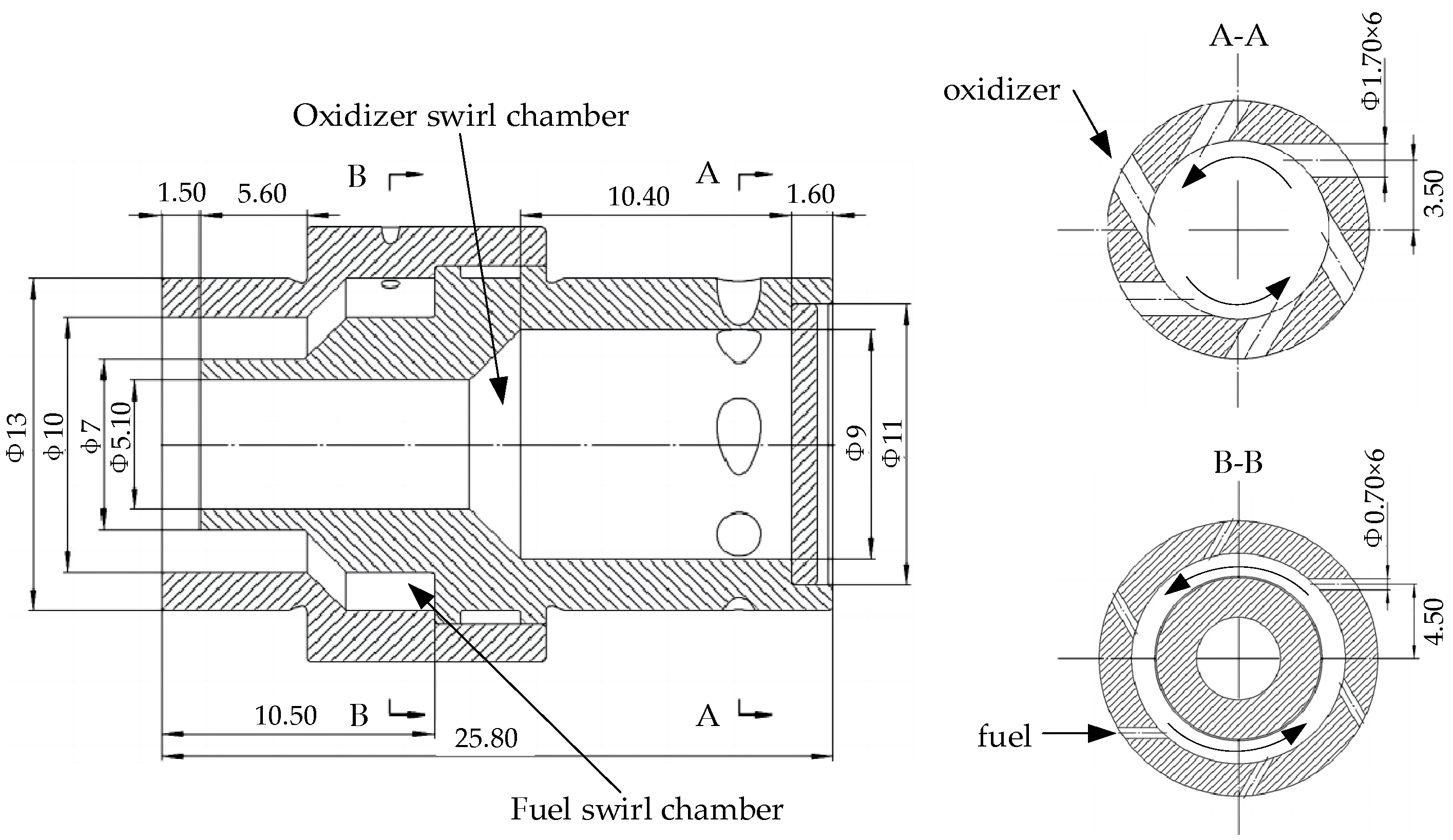
The Russian space program developed a liquid rocket coaxial swirl injector, which was notably implemented for the first time in the RD-0110 liquid oxygen (LOx)/kerosene engine (developed at KB Khimavtomatiki design bureau, a.k.a KBKhA in the city of Voronezh) of the Soyuz spacecraft’s third stage [18], as shown in Figure 1. In this design, the fuel and oxidizer primarily enter through 12 tangential holes into the fuel swirl chamber and the oxidizer swirl chamber, respectively. Notably, the oxidizer swirl chamber features a converging design, while the fuel swirl chamber has an open design. In this layout, the oxidizer swirl chamber slightly narrows, adopting an external mixing approach. Currently, there is a wealth of research on the coaxial swirl injector of the RD-0110 engine [19,20,21,22,23,24]. This paper is primarily based on the dimensions of the oxidizer swirl chamber in the RD-0110 coaxial swirl injector. To achieve the anti-backflow function, an expansion opening is set at the nozzle based on the principle of a one-way valve, allowing the liquid propellant to be injected through the gap between the valve core and the expansion opening. Considering the working characteristics of the rotating detonation engine, a novel concave valve core is designed to effectively prevent high-temperature products from backflowing into the injection pipeline over a short distance. The concave valve core combines the sealing advantages of a ball valve with the lower flow resistance of a cone valve.
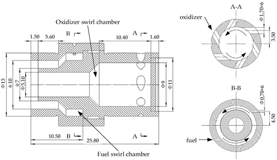
Figure 1.
Coaxial swirl injector of RD–0110.
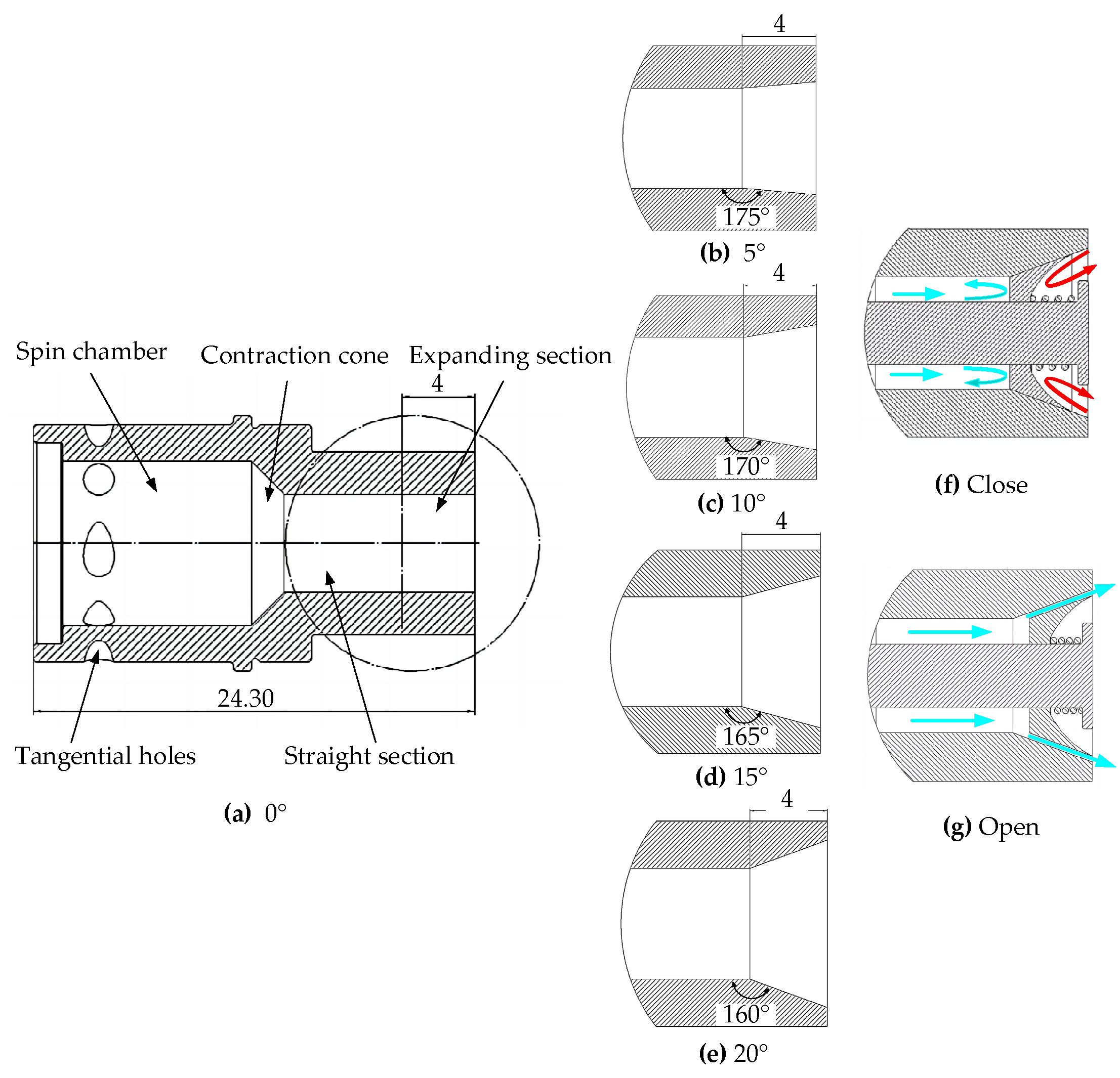
This study focuses on a detailed analysis of four different structures of centrifugal injectors. Firstly, as a baseline model, the oxidizer injection model from the RD-0110 engine’s coaxial injector is utilized. Secondly, to further optimize the design, an expansion mouth model is introduced to improve the baseline model. An expansion mouth is added 4 mm from the injector outlet, exploring different expansion angles—5°, 10°, 15°, and 20°—to assess their impact on injection performance. Lastly, we propose an anti-recirculation model, which is a further innovation based on the expansion mouth model. This model includes key components such as a central guide rail, concave valve core, limiting screw, and springs. It is designed to enhance the efficiency of the injector while preventing the backflow of high-temperature products. This comprehensive approach aims to address the challenges in injector design and performance, particularly in the high-pressure, high-temperature environments typical of rocket engine operations.
The internal structure of the baseline model is specified as follows: the swirl chamber has a length of 10.4 mm and a diameter of 9 mm. It contains six tangential holes, each with a cross-sectional diameter of 1.7 mm, located 2 mm from the top cover; the contraction section angle is set at 45°; the equal diameter section has a length of 20.75 mm and a diameter of 5.4 mm, as shown in Figure 2a. The main feature of the expansion mouth model is the addition of an expansion mouth at the outlet part of the equal diameter section. The research by Liu et al. [25] showed that each 2° increase in the expansion angle of the injection port caused a change in liquid film thickness that was greater than the change caused by a 1 mm increase in nozzle diameter. Therefore, in this paper, the expansion mouth was designed with angles of 5°, 10°, 15°, and 20°, while other dimensions remained the same as in the baseline model, as drawn in Figure 2b–e. The core design of the anti-recirculation model is the addition of a central guide rail at the top of the swirl chamber in the expansion mouth model. The central guide rail is equipped with a limiting screw at the outlet of the injector, mainly to prevent the concave valve core from falling off. A spring is placed between the limiting screw and the concave valve core, primarily aiming to maintain the parallelism of the concave valve core during the sliding process. The concave valve core is located below the spring, and its working principle is as follows: when the pressure inside the swirl chamber is greater than the external pressure, the concave valve core moves towards the outlet; on the contrary, when the external pressure is greater than the pressure in the swirl chamber, the concave valve core moves towards the interior of the swirl chamber, thus achieving the effect of preventing backflow, as shown in Figure 2f,g.
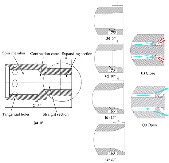
Figure 2.
(a) Baseline injector model with an expansion port angle of 0°; (b) expansion port angle of 5°; (c) expansion port angle of 10°; (d) expansion port angle of 15°; (e) expansion port angle of 20°; (f) anti–backflow injector close model (blue arrows indicate propellants, while red arrows indicate high–temperature products); (g) anti-backflow injector open model.
2.2. Mathematical Model
In what follows, we use the Navier–Stokes equation (NS equation) as the core basis. In order to simplify the analysis process, we adopt the ideal fluid assumption proposed by Abramovich [26]. Most liquids’ density changes very little within the common range of pressure variations, so they can be approximately considered as incompressible. While all real liquids have some viscosity, in many cases, the viscous forces are negligible compared to inertial and pressure forces. Therefore, ideal liquids are regarded as incompressible and inviscid media. On this basis, the dynamic viscosity μ of the fluid is set to zero. This simplification allows the Navier–Stokes equation to be transformed into the more compact Euler equation. Next, we further consider the one-dimensional model of fluid motion and assume that the flow along streamlines is stable. In this case, Bernoulli’s equation (see Equation (1)) is introduced to describe the dynamic behavior of the fluid.
where represents the fluid velocity field, denotes the pressure field, is the density, is the acceleration due to gravity, and is the height of the fluid relative to a reference point.
Based on the continuity equation, the relationship for the inlet velocity can be derived (see Equation (2)).
where represents the inlet velocity, denotes the number of inlets, indicates the cross-sectional area of the inlet, and stands for the mass flow rate.
Reddy Ku et al. [27] conducted a study on the geometric differences between conical swirl injectors and swirl injectors with tangential inlets, indicating that the main differences are the helix angle ‘’, located in a vertical plane parallel to the xz plane, and the swirl angle ‘’, as shown in Figure 3. From this, the tangential velocity at the inlet can be obtained:

Figure 3.
(a) Conical swirl injector; (b) tangential swirl injector [28].
Assuming that the angular momentum and axial velocity are constant at the outlet cross-section, the tangential and axial velocities at the outlet can be expressed as follows:
where represents the tangential velocity at the outlet, denotes the tangential velocity at the inlet, is the perpendicular distance from the circle center to the tangential empty shaft line at the inlet cross-section, and refers to the radius of the air core at the outlet cross-section. When the liquid propellant enters the swirl chamber through the tangential port at a certain speed, it will rotate along the chamber wall under the action of centrifugal force, eventually forming a rotating conical liquid film at the nozzle outlet. Therefore, an air core, hereafter referred to as ‘gas eddy’, is formed in the center of the swirl chamber.
Herein, denotes the axial velocity at the outlet and represents the radius of the outlet.
According to Equation (6), the relationship between the pressure drop and the tangential and axial velocities at the outlet can be deduced:
The relationship between mass flow rate and total pressure drop is expressed through the discharge coefficient:
According to Equation (7), by grouping it into terms of the thin-film flow area coefficient and applying the principle of maximum mass flow rate , we can obtain the geometric parameter ‘Ac’ for the conical pressure swirl atomizer, as shown in Equation (8) [29]. However, when the inlet passages are tangentially distributed along the swirl chamber, the geometric parameter ‘Ac’ can be simplified to ‘A’ , as illustrated in Equation (9):
Kessaev K et al. [30] represented the discharge coefficient and the spray half-angle using the mold flow coefficient ‘φ’, as shown in Equations (10) and (11):
However, in actual flow, due to the viscosity of the liquid, it is necessary to consider the loss of angular momentum ‘K’ and hydraulic losses ‘’. After modifying the Bernoulli equation and equivalent discharge coefficient to account for these parameters, it can be represented by Equations (12) and (13) [31]. Here, the hydraulic loss ‘’ represents losses caused by the geometric shape of the inlet passage, which is a function of the inclination angle ‘’ . [32] denotes losses due to fluid friction on the channel walls, related to the friction factor ‘’ .
Finally, by applying Abramovich’s jet theory to actual flow (maximum flow), the equivalent constructive geometric parameter by Kliachko can be derived [33] (Equation (14)), from which the equivalent film flow coefficient ‘’ is obtained. Consequently, the equivalent discharge coefficient (Equation (15)) and the equivalent spray half-angle (Equation (16)) can be determined [31,34].
2.3. Steady-State CFD Simulation
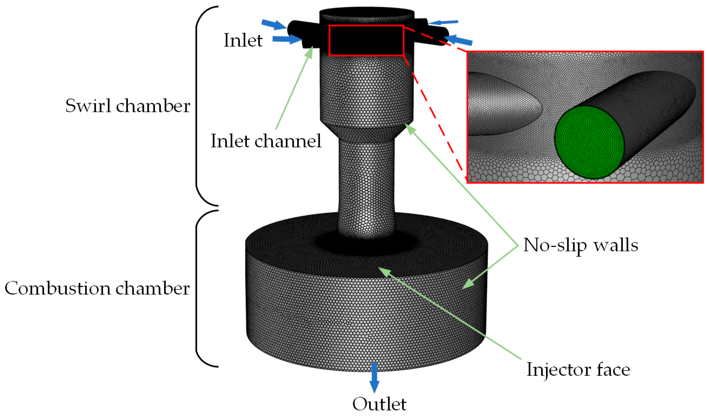
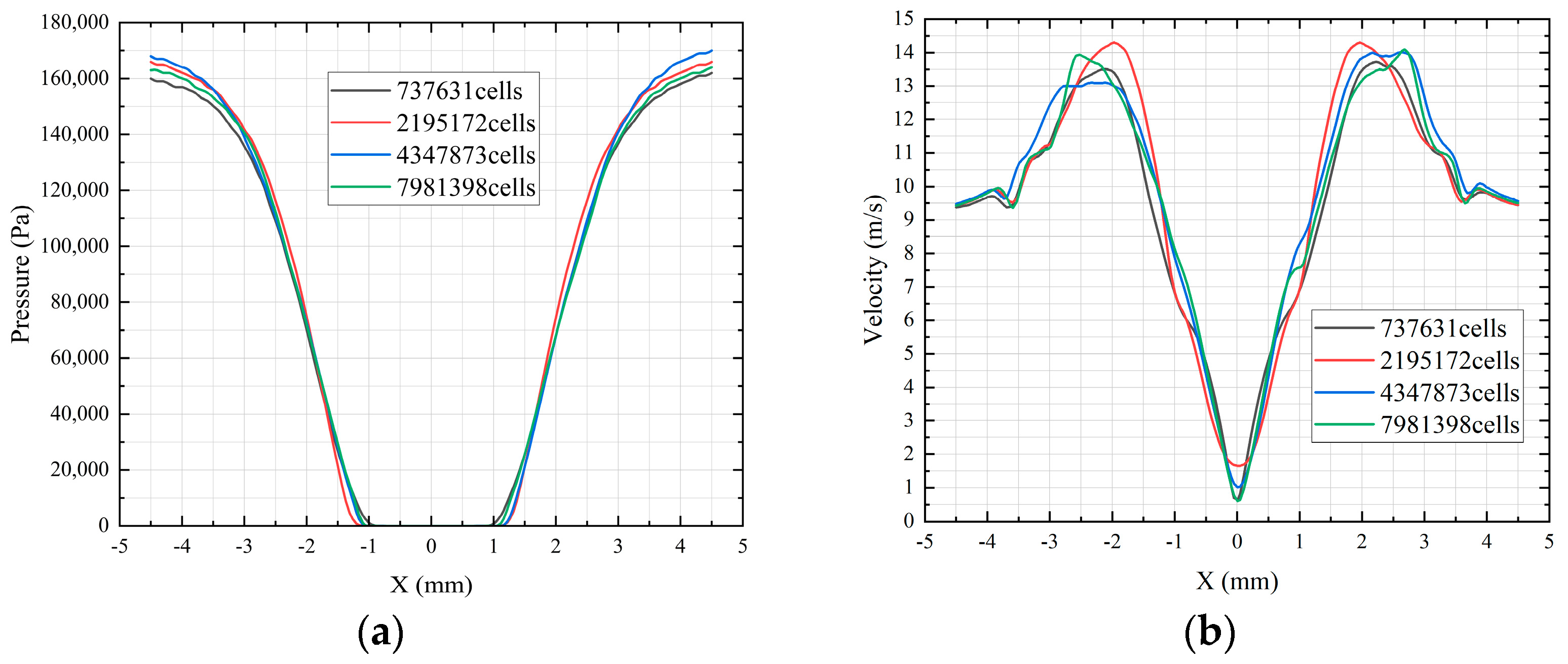
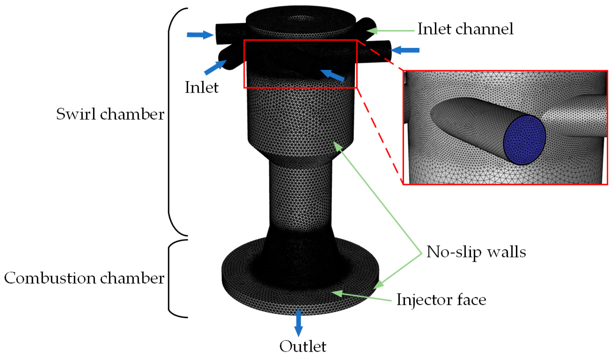
This paper’s numerical simulation is divided into two components, with the first part focusing on steady-state simulation. This aims to study the forward-flow characteristics of injectors without anti-backflow devices. The simulation work was carried out using the Volume of Fluid (VOF) multiphase flow model integrated in Fluent (2020R2) software. Since only the flow state in the anti-backflow injector needs to be considered, without considering combustion, in this model, air was set as the first phase and water as the second phase, satisfying the condition that the sum of the volume fraction of air and the volume fraction of water equals 1.The grid was primarily generated using Fluent meshing (2020R2) software, which combines the shared-node connection of hexahedral and polyhedral meshes, also supporting the division of boundary layer grids. Thus, layered Poly grids can be used near wall surfaces, pure Poly grids can be used in transitional areas, and hexahedral grids can be used in core areas, as shown in Figure 4. This grid structure not only improves grid quality but also effectively reduces the total number of grids and the computation time. In this study, unstructured meshing techniques were used to create an initial mesh of 7.3 × 10⁵, 2.19 × 10⁶, 4.34 × 10⁶ and 7.98 × 10⁶ cells for grid independence verification. As shown in Figure 5, the analysis of pressure and velocity distribution at the inlet cross-section revealed that consistent results were obtained in terms of in pressure and velocity distributions when the grid count reached 2.19 × 10⁶, 4.34 × 10⁶, and 7.98 × 10⁶ cells. Considering computational efficiency, we ultimately selected 4.34 × 10⁶ grid cells for subsequent simulation work. This approach ensures the accuracy of results while minimizing the demand on computational resources.
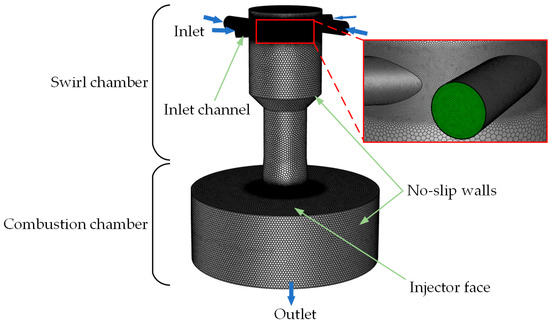
Figure 4.
Steady-state simulation mesh.
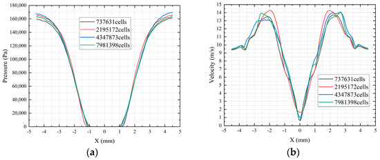
Figure 5.
Grid independence verification: (a) pressure distribution at the inlet cross-section; (b) velocity distribution at the inlet cross-section.
For grid independence, it is necessary to consider the non-dimensional wall distance (Equation (17)). Based on this parameter, one can determine an approximately suitable region for resolving turbulent phenomena [31].
where represents the density of the liquid, is the friction velocity, is the height from the wall to the center point of the first layer of the grid, and denotes the viscosity.
In this paper, the considered inlet velocity ranged from 7.5 m/s to 13 m/s, with the hydraulic diameter , which is the cross-sectional diameter of the tangential port. The Reynolds number can be calculated using Equation (18):
Inserting the values of the Reynolds number into Equation (19) leads to an estimation of the wall friction coefficient :
The wall friction coefficient can be inserted into Equation (20) to calculate the wall shear stress :
Finally, inserting the wall shear stress into Equation (21) yields the friction velocity :
To ensure the accuracy of the computational results, Fluent requires that must be greater than 15; if is less than 15, Fluent cannot guarantee the accuracy of the solution. Therefore, setting to 30 allows for the derivation of the center height of the first layer of the grid through Equation (1) ( = 0.045 mm). However, when is less than 11, the standard wall function cannot be used. Hence, this paper chose the ‘extended wall function’. The extended wall function is an extension of the standard wall function, as shown in Equation (22). Specifically, when is less than 11.25, the value of is calculated using 11.25; if is greater than or equal to 11.25, the original value is used in calculations. Subsequently, the RNG model is employed to achieve convergence of this criterion.
In this formula, .
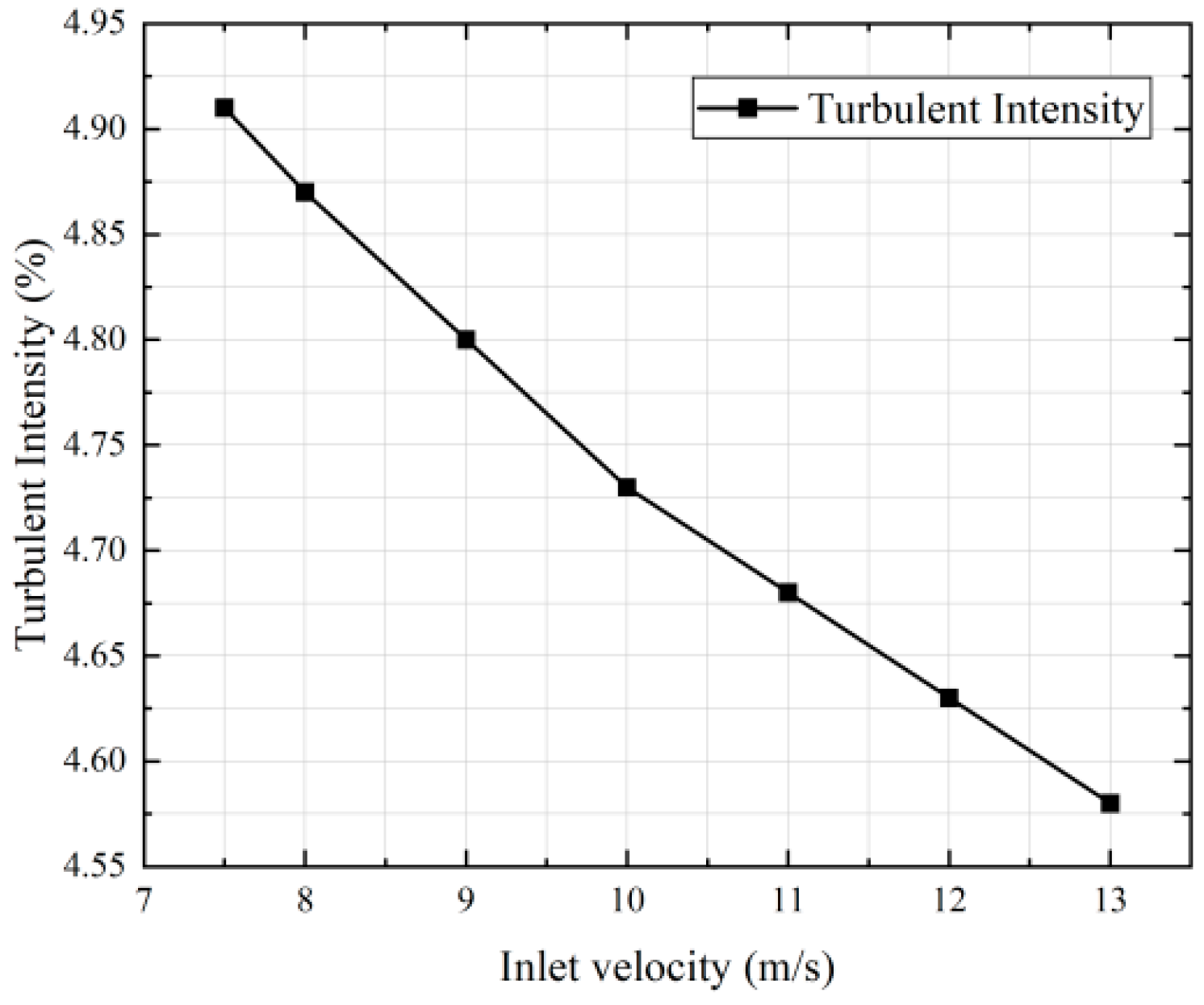
In the setup of the model, we defined the inlet condition as a velocity inlet, using turbulence intensity (I) and hydraulic diameter (Dh) as the primary parameters. The calculation of turbulence intensity follows Equation (23), with its trend illustrated in Figure 6. Additionally, the phase fraction of water at the inlet was set to 1, indicating that the flow that entered the swirl chamber is entirely composed of water. A virtual numerical outlet was set 9 mm from the physical outlet. This outlet is defined as a pressure outlet, with no liquid backflow occurring. Such a setup allows us to accurately simulate the flow behavior inside the injector while maintaining physical realism, providing crucial data support for the design and optimization of the injector.
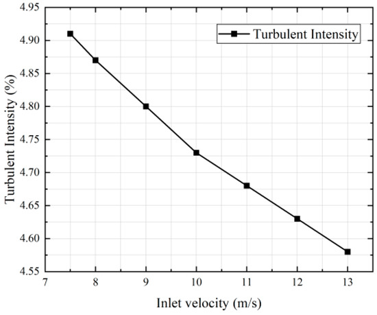
Figure 6.
Variation in turbulence intensity.
2.4. Transient CFD Simulation
In the second part of the numerical simulation, we used a transient model to simulate the backflow transient flow behavior of the injector under the influence of the high pressure generated by the combustion chamber. Due to the movement of the valve core involved in the backflow process, in order to make the simulation process more flexible, accurate, and stable, we used Fluent meshing software to automatically generate unstructured tetrahedral meshes. After a brief mesh study, we selected 1.35 × 10⁶ grid cells for the subsequent transient simulation. The mesh is shown in Figure 7. The core purpose of this part of the simulation is to assess the backflow phenomenon of the liquid propellant, as well as the dynamic interaction with the concave valve, when the anti-backflow injector faces pulse pressure changes in the combustion chamber. Prior to the transient simulation, a steady-state simulation of single-phase flow was first conducted, representing the normal forward flow state. In this phase, the pressure inlet condition was set to 300 Pa, while the pressure outlet condition was defined as 0 Pa, a no-slip boundary condition was applied to the injector walls, which were also assumed to have no surface roughness. An SST-k-ω turbulence model was applied and liquid water was used as the working fluid. Through the steady-state simulation, the pressure of the combustion chamber was obtained. Subsequently, in the transient simulation, three different stiffness values for the injector were considered: 150%, 50%, and 20%. The definition of injector stiffness IS is as follows [17]:
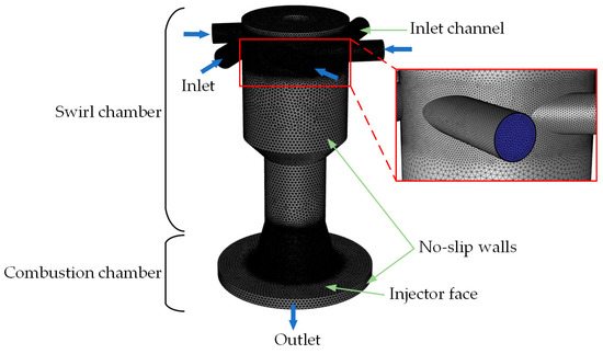
Figure 7.
Transient simulation mesh.
In this formula, represents the pressure difference during the steady-state simulation, is the inlet pressure, and is the combustion chamber pressure in the chamber during the steady-state simulation.
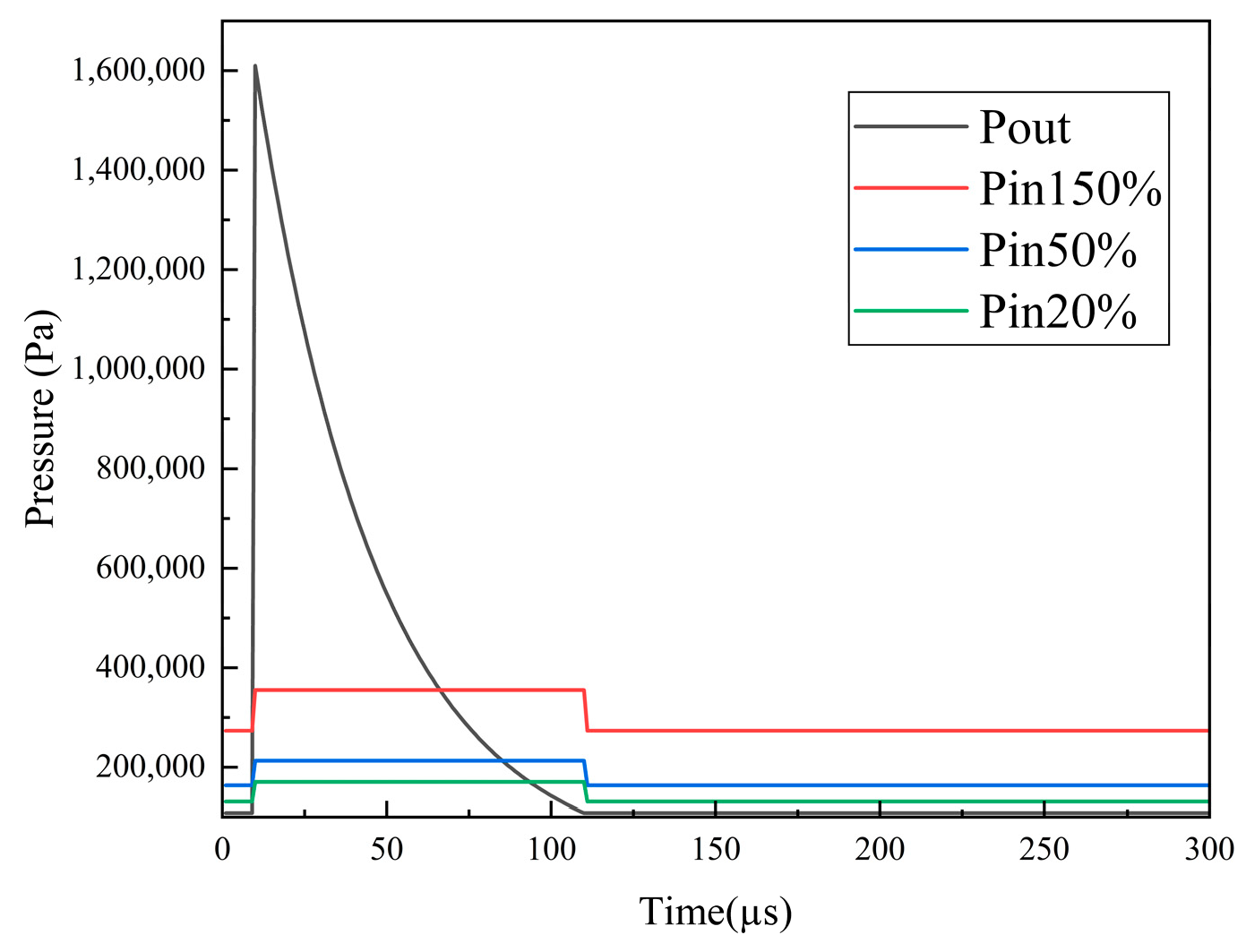
The transient simulation of the anti-backflow injector was conducted using ANSYS (2020R2) Fluent, selecting a pressure-based solver and employing the multiphase flow VOF model for the transient simulation. Liquid water and air were used to represent the propellant and combustion gases, respectively. The inlet pressure values were set by changing the stiffness values, while the nominal chamber pressure and the pulse peak remained constant. The movement of the concave valve was implemented by dynamically re-meshing the grid in the moving mesh technology using a six degrees of freedom (six-DOF) model. The results of the steady-state simulation were used as the initial conditions for the transient simulation to represent the forward-flow state at the start of the simulation, reflecting the actual conditions before the occurrence of high-pressure pulses. Additionally, to simulate the spin chamber pressure response caused by a sudden increase in combustion chamber pressure, a basic step function was employed. Specifically, when high pressure occurred in the combustion chamber, the inlet pressure would increase by 30% [18]. Alex R. Keller et al. [17] summarized the study on manifold pressure variations at Purdue University and assumed an exponential decay function to simulate the high-pressure variations in the combustion chamber. In the model, a time-varying outlet boundary condition was set to simulate this pressure change, which was specifically adjusted to 10 µs [18,35,36], and the pressure returned to its initial value at 110 µs. This was to replicate the pressure environment when a detonation wave passed through the injection outlet, as shown in Figure 8.
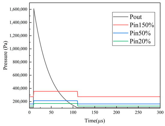
Figure 8.
Relative Pressure versus time graph for the transient boundary conditions at the outlet and Inlet.
The performance of the anti-backflow injector was evaluated by assessing the flow recovery time scale, as given in Equation (25).
In this formula, represents the refill time, represents the time when the mass flow rate begins to rise, and represents the time when the mass flow rate starts to decrease.
3. Results and Analysis
3.1. Forward Flow Parameter Analysis
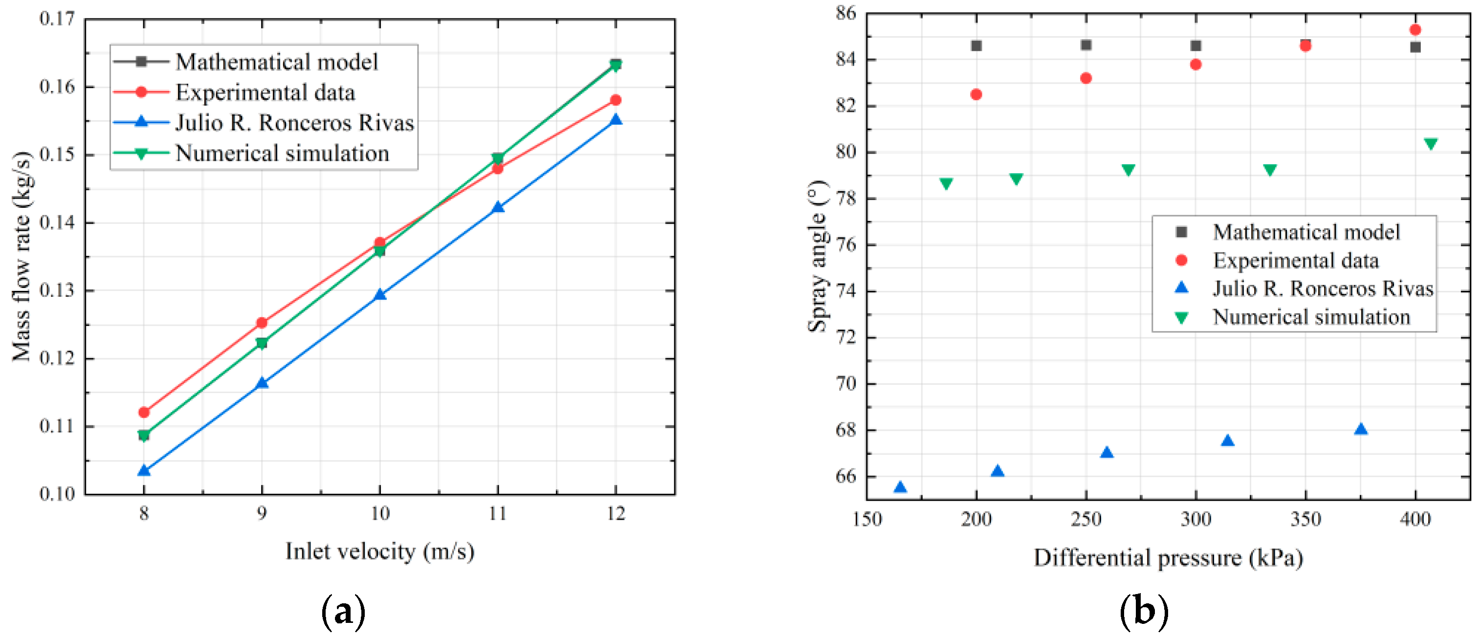
To ensure that the anti-backflow device does not negatively impact the forward flow of the injector, this study conducts forward flow simulations on injectors without anti-backflow devices and with different expansion ports. Given our focus on the final results rather than the entire flow process, a pressure-based steady-state method was chosen for the simulation. Before proceeding with the steady-state simulation, we first reexamined the simulation results of Julio R. Ronceros Rivas and others [28] for the RD-0110 coaxial swirl injector. During this process, we focused on the relationship between inlet velocity and mass flow rate (Equation (2)), as well as the spray angle (Equation (16)). Further, we compared and analyzed these mathematical results with the experimental observations. This process not only verifies the accuracy of our simulation model but also provides an important basis for understanding the flow characteristics of the injector. The results of this comparative analysis, as shown in Figure 9, guided us in correctly setting simulation parameters for the subsequent research.
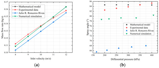
Figure 9.
Comparison of replicated data from the literature: (a) variation in inlet mass flow rate; (b) spray angle [28].
The numerical simulation results in this study show a high degree of consistency with the predictions of the mathematical model, and they align within an acceptable error margin with experimental data. This consistency validates the accuracy and reliability of our simulation methodology. As evidenced in Figure 9b, the numerical simulation results are closer to the experimental data [37] and the mathematical model compared to the numerical simulations by Julio R. Ronceros Rivas et al. [28], with the primary source of error being the significantly shorter measurement distance used in our study compared to the experimental measurements. Based on these findings, we can conclude that the results produced by our numerical simulations are highly credible. This provides strong support for our use of numerical simulations to model the forward flow in injectors without anti-backflow devices.
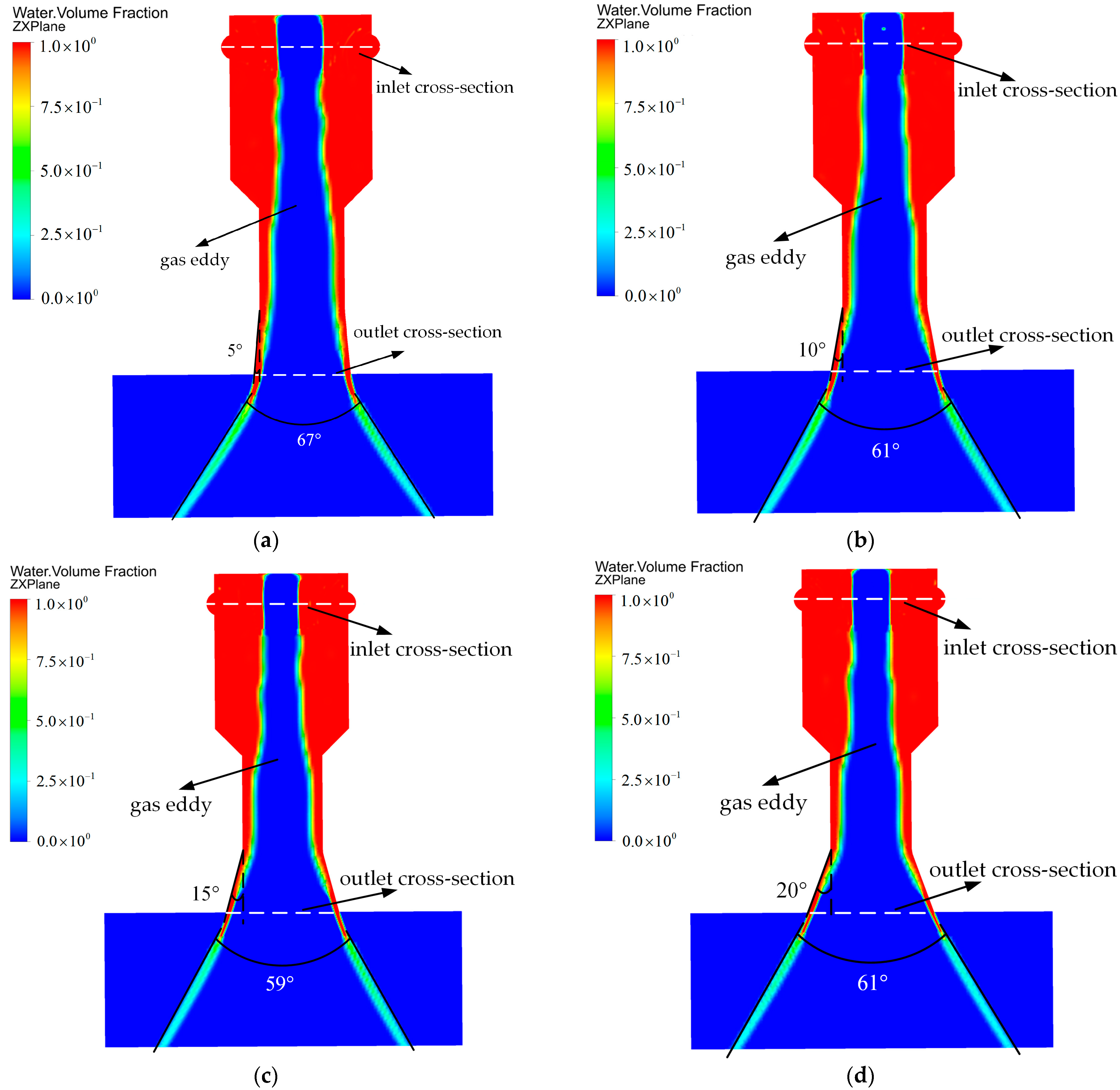
Figure 10 displays the distribution of water volume in the ZX plane at different expansion port angles when the inlet velocity is 10 m/s. It can be observed that, influenced by the centrifugal force of the liquid, a gas eddy is formed in the center of the swirl chamber. Concurrently, a conical spray angle is formed as the liquid exits the injector.
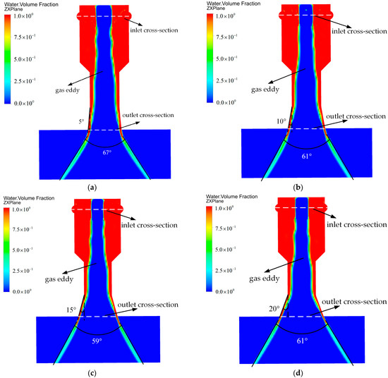
Figure 10.
Distribution of water volume fraction in the ZX plane at an inlet velocity of 10 m/s: (a) water volume fraction distribution with an expansion port angle of 5°; (b) water volume fraction distribution with an expansion port angle of 10°; (c) water volume fraction distribution with an expansion port angle of 15°; (d) water volume fraction distribution with an expansion port angle of 20°.
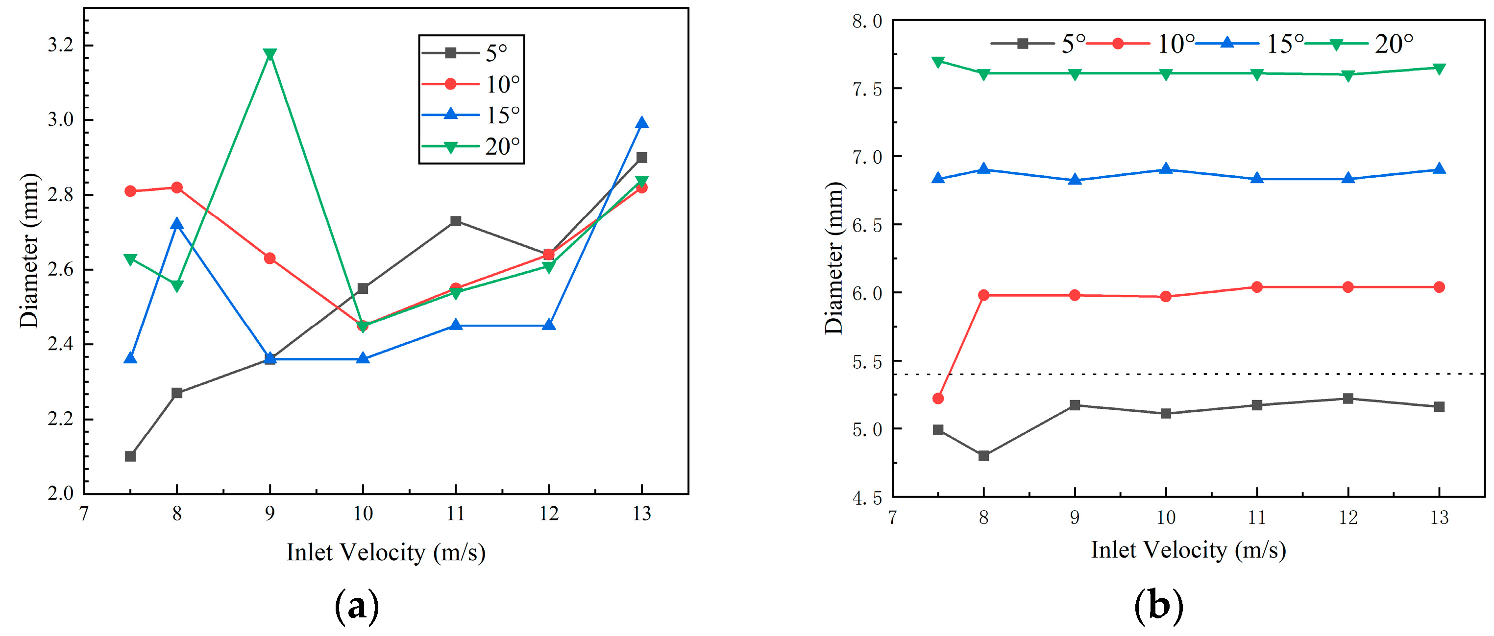
Figure 11 shows the distribution of the gas eddy diameter at the inlet and outlet cross-sections under different inlet velocities. Analyzing the distribution of the gas eddy diameter at the inlet cross-section in Figure 11a, it is found that with the increase in inlet velocity, the diameter of the gas eddy at the inlet also tends to increase, especially when the inlet velocity exceeds 10 m/s, at which point this phenomenon becomes particularly pronounced. However, when the inlet velocity is between 7.5 m/s and 9 m/s, the diameter distribution of the gas eddy at the inlet cross-section does not show a clear pattern, mainly due to the instability of the pressure throughout the injector. An unstable pressure can cause certain deformations in the gas eddy, leading to deviations in the measured values. As the inlet velocity increases, the pressure in the injector becomes more stable, thus making the trend of increasing gas eddy diameter with increasing velocity more apparent. From the distribution of the gas eddy diameter at the outlet cross-section in Figure 11b, it is seen that the diameter of the gas eddy at the outlet does not show a significant correlation with the change in inlet velocity, and the diameter at the outlet appears consistent. However, there is a positive correlation between the gas eddy diameter at the outlet and the angle of the expansion port, meaning that the diameter of the gas eddy at the outlet also gradually increases as the angle of the expansion port increases. These findings are significant for optimizing the design of the injector, particularly in terms of optimizing the design of the central guide rail and the anti-backflow block.
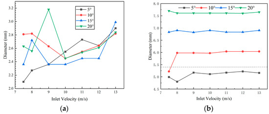
Figure 11.
Distribution of gas eddy diameter: (a) gas eddy distribution at the inlet cross−section; (b) gas eddy distribution at the outlet cross-section (the dashed line represents the minimum diameter of the swirl chamber).
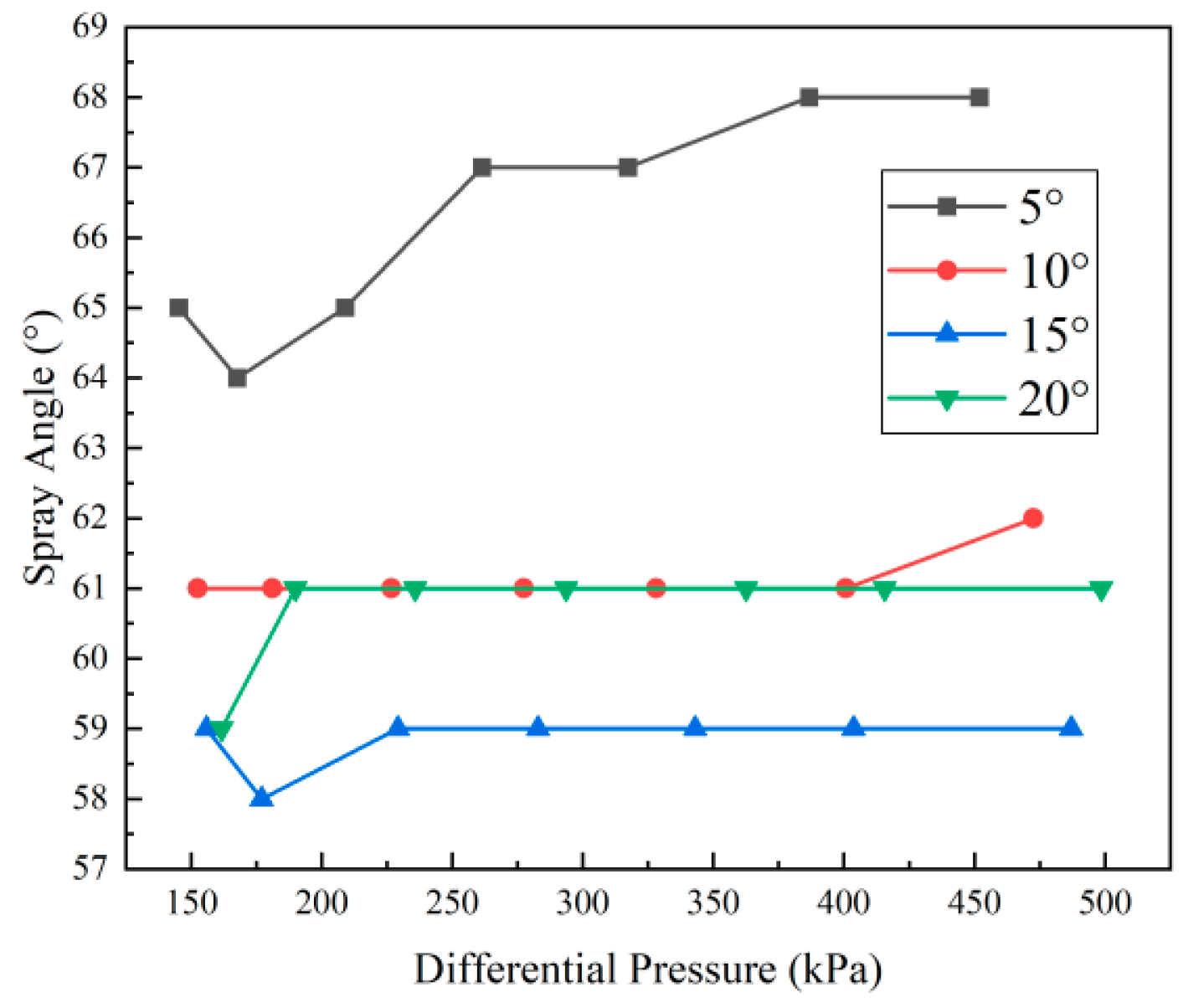
Figure 12 shows the distribution of the spray angle of the conical liquid film under different pressure differential conditions. It can be observed from the figure that as the expansion port angle increases, the extent to which the spray angle is influenced by the pressure differential gradually decreases. Specifically, when the spray angle is set to 5°, the spray angle shows an upward trend with the increase in the pressure differential. However, when the expansion port angles are set to 10°, 15°, and 20°, respectively, the sensitivity of the spray angle to the pressure differential significantly decreases. Notably, when the spray angles are set to 10° and 20°, the spray angles almost remain consistent, with both at 61°. Meanwhile, with a 15° setting, the spray angle slightly decreases to 59°.
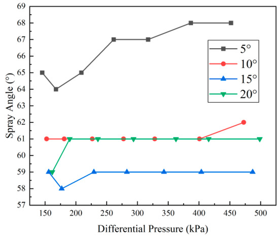
Figure 12.
Distribution of spray angle under different pressure differentials.
In this study, we first used steady-state simulation to simulate injectors without anti-backflow devices, aiming to analyze the forward-flow characteristics of injectors under different expansion angles while laying the groundwork for the subsequent design of anti-backflow devices. To ensure that the concave valve does not affect the forward-flow performance of the injector, the diameter of the anti-backflow guide rail should be set to be less than or equal to the average inlet gas eddy diameter. When designing the anti-backflow baffle, it is necessary to ensure that the maximum diameter of the baffle does not exceed the minimum diameter of the outlet gas eddy under different expansion port angles. As observed in Figure 11a, the diameter of the gas eddy at the inlet section mainly ranges between 2.2 and 3 mm. Based on this observation, we designed the diameter of the anti-backflow guide rail to be 2.5 mm. The results from Figure 11b show that when the spray angle is set to 5°, the diameter of the gas eddy at the outlet is less than the minimum diameter of the swirl chamber at 5.4 mm, indicating that adding an anti-backflow device in this setting would not achieve the desired backflow prevention. Therefore, 5° expansion angle setting is not suitable for the design of anti-backflow injectors. However, when the expansion angles are set to 10°, 15°, and 20°, the diameter of the gas eddy at the outlet is greater than the minimum diameter of the swirl chamber, indicating that these expansion angles are suitable for the design of anti-backflow injectors. Specifically, with an expansion angle of 10°, the average gas eddy diameter at different velocities is 5.89 mm, so we set the maximum diameter of the concave valve to 5.89 mm. Similarly, with an expansion angle of 15°, the maximum diameter of the concave valve is 6.6 mm, and at an expansion angle of 20°, the maximum diameter of the concave valve is set to 7.6 mm. Such a design ensures that the anti-backflow device effectively prevents backflow without interfering with the normal operation of the injector.
3.2. Anti-Backflow Parameter Analysis
In the process of transient simulation, we specifically monitored the mass flow rate at the outlet of the injector to evaluate the response time of the concave valve core in the anti-backflow injector for blocking the entry of high-temperature products into the manifold. These parameters are crucial for assessing the performance of the anti-backflow injector. Specifically, the time it takes for the mass flow rate at the outlet to drop from a stable value to zero represents the response time of the concave valve core. This reflects the length of time it takes for the concave valve core to start acting and completely block the entry of high-temperature products into the swirl chamber. For the anti-backflow injector, the ideal situation is that its response time is as short as possible. A short response time can effectively reduce the risk of high-temperature products entering the swirl chamber, thereby improving the safety and efficiency of the injector.
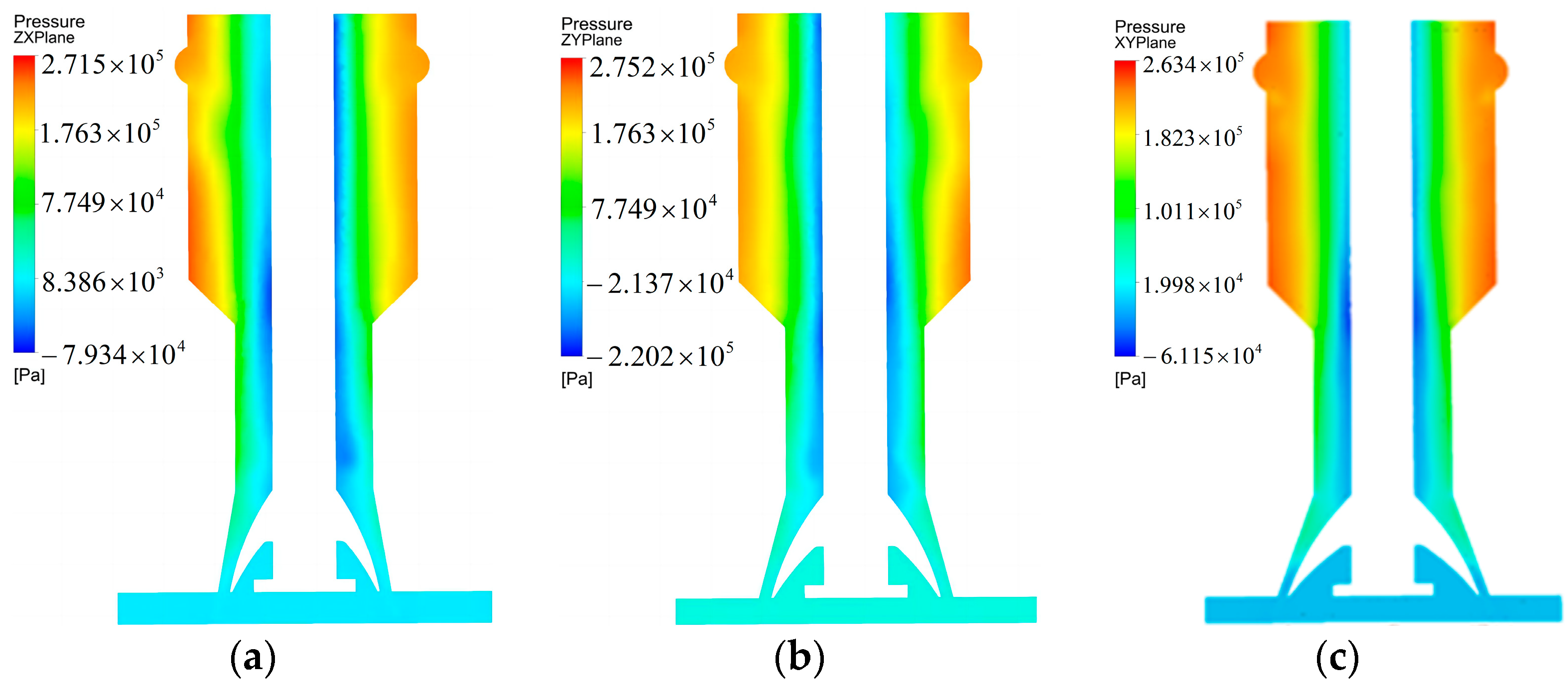
Figure 13 presents the results of the single-phase steady-state simulation. Through these steady-state simulation results, the chamber pressure for different expansion ports can be determined, thereby establishing the pressure inlet conditions for the transient simulation using Equation (24).
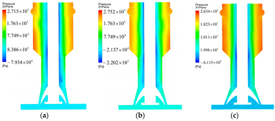
Figure 13.
Pressure distribution in single-phase steady-state simulation: (a) pressure distribution at an expansion angle of 10 degrees; (b) pressure distribution at an expansion angle of 15 degrees; (c) pressure distribution at an expansion angle of 20 degrees.
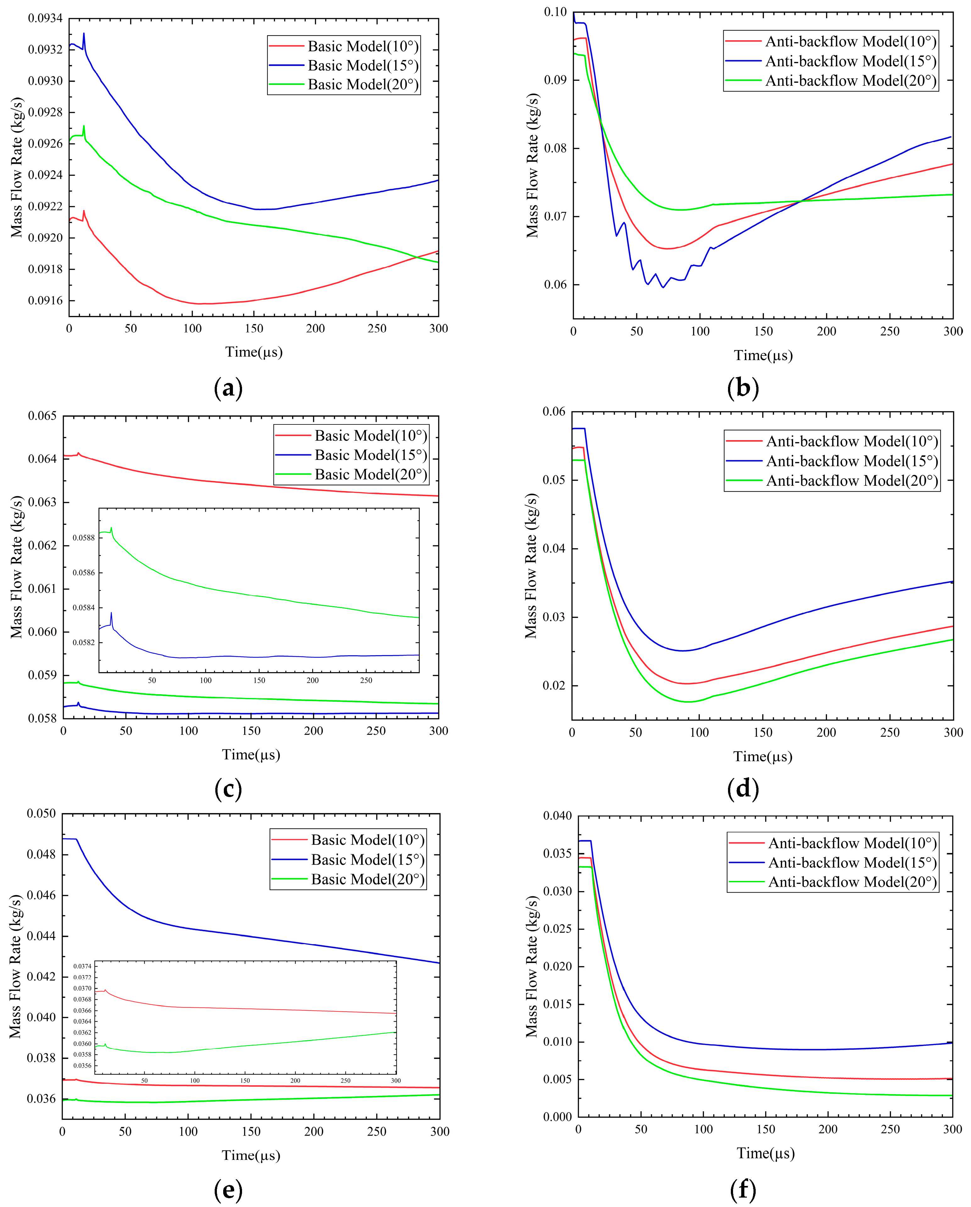
Figure 14 illustrates the mass flow rate over time for basic models (without anti-backflow devices) and anti-backflow models (equipped with anti-backflow devices) under varying injection stiffness values. From Figure 14a, it can be observed that under a high injection stiffness (150%) with outlet expansion angles of 10° and 15°, the mass flow rate at the outlet begins to decrease with the sudden increase in external pressure. As the external pressure diminishes, the mass flow rate starts to rise after 144 µs and 169 µs, marking the onset of the recovery injection. However, for the 20° expansion angle, no rise in mass flow rate is observed. This might be attributed to the increased outlet diameter due to the larger expansion angle, which, under rising external pressure, amplifies the pressure changes in the swirl chamber, thereby prolonging the recovery injection time, finally resulting in no recovery of mass flow rate within 300 µs. A sudden change in mass flow rate at 10–15 µs, mainly due to a sharp increase in external pressure at that moment, causes some of the already ejected propellant to re-enter the swirl chamber, leading to a sudden increase in mass flow rate at the outlet. This phenomenon indicates that basic models without anti-backflow devices (with expansion angles of 10°, 15°, and 20°) all suffer from the issue of ejected propellant flowing back into the swirl chamber. Figure 14b shows anti-backflow models with expansion angles of 10°, 15°, and 20° under high injection stiffness. It can be seen that the mass flow rates of these three anti-backflow models all recover within 100 µs, indicating that their recovery injection times are completed within this timeframe, demonstrating the significant performance advantage of the anti-backflow injectors. The mass flow rate recovery speed varies among different expansion angle anti-backflow models, with the 15° expansion model recovering the fastest, followed by the 10° model, and the 20° expansion model being the slowest. Compared to the basic models, the anti-backflow models at 10 µs do not exhibit a sudden change in mass flow rate but gradually decrease from the initial mass flow rate with a sudden increase in outlet pressure. This indicates that, with the anti-backflow device installed, there is no occurrence of ejected propellant flowing back into the swirl chamber, effectively reducing the risk of hypergolic propellant-induced explosions due to oxidizer/fuel entering the opposing swirl chamber. Using an injection stiffness of 150% and a timeframe of 300 µs as an example, the anti-backflow models with 10°, 15°, and 20° expansion angles show respective increases in recovery injection time of 67 µs, 99 µs, and 213 µs compared to the basic models with the same expansion angles.
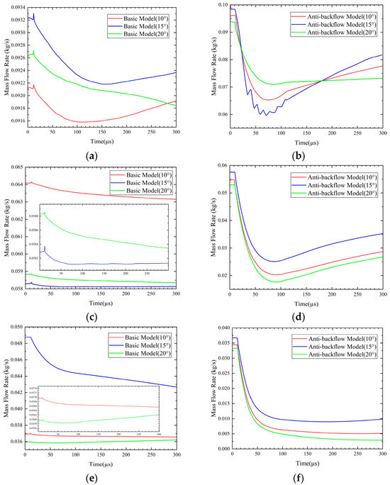
Figure 14.
Recovery time comparison chart: (a) distribution of recovery times for basic models at an injection stiffness (IS) of 150%; (b) distribution of recovery times for anti-backflow models at an IS of 150%; (c) distribution of recovery times for basic models at an IS of 50%; (d) distribution of recovery times for anti-backflow models at an IS of 50%; (e) distribution of recovery times for basic models at an IS of 20%; (f) distribution of recovery times for anti-backflow models at an IS of 20%.The enlarged parts show trends in mass flow.
Figure 14c presents the variation in mass flow rate over time for basic models with different expansion angles at an injection stiffness of 50%. The analysis indicates that for the basic models with expansion angles of 10° and 20°, the mass flow rate continuously declines, suggesting that these models do not achieve recovery injection within the 300 µs observation window. The basic model with a 15° expansion angle shows slight fluctuations in mass flow rate after 92 µs. However, considering the overall range of mass flow rate changes, it can be concluded that recovery injection was not achieved within 300 µs. Concurrently, all models experience a surge in mass flow rate at 10 µs, reaffirming the issue of the ejected propellant flowing back into the swirl chamber in basic models without anti-backflow treatment. On the other hand, Figure 14d shows the performance of anti-backflow models with different expansion angles. These models demonstrate a significant anti-backflow effect, achieving recovery injection at around 90 µs and exhibiting no instances of the propellant flowing back into the swirl chamber throughout the observation period. Compared to the basic models, the anti-backflow models exhibit a marked performance improvement under 50% injection stiffness. Within a 300 µs timeframe, the anti-backflow models with 10°, 15°, and 20° expansion angles show respective improvements in recovery injection time of 207µs, 210 µs, and 207 µs compared to the basic models with the same expansion angles. These results highlight the crucial value of anti-backflow devices in enhancing injector performance and reducing the risk of propellant backflow.
Figure 14e reveals the changes in mass flow rate for basic models with different expansion angles at an injection stiffness of 20%. The results show that the basic models with expansion angles of 10° and 15° do not exhibit any increase in mass flow rate during the 300 µs observation period. However, for the basic model with 20° expansion angle, the mass flow rate begins to rise at 84 µs. Notably, all these basic models record a slight surge in mass flow rate between 10 and 15 µs, indicating a recurrence of the situation where a portion of the ejected propellant flows back into the swirl chamber. From Figure 14f, it can be observed that, under a reduced injection pressure, the anti-backflow models with different expansion angles do not show a significant recovery response. Specifically, the anti-backflow models with expansion angles of 10° and 15° begin a slow rise in mass flow rate at 259 µs and 204 µs, respectively, while the 20° expansion angle anti-backflow injector does not exhibit any increase in mass flow rate throughout the 300 µs observation period. Under an injection stiffness of 20%, compared to the basic models, the anti-backflow models with 10° and 15° expansion angles show improvements in response recovery injection time of 41 µs and 96 µs, respectively, within the 300 µs timeframe. However, the performance of the anti-backflow model with a 20° expansion angle is 216 µs slower than the basic model, indicating significant performance differences among anti-backflow models with various expansion angles under low injection stiffness conditions.
From Table 1, we can analyze the re-injection times of basic and anti-backflow models under different injection stiffness conditions and draw the following conclusions: under high injection stiffness conditions, the anti-backflow model with a 15° expansion angle demonstrates the fastest re-injection speed, starting at 70 µs, followed by the 10° expansion angle model at 77 µs, and the 20° expansion angle model beginning at 87 µs. Compared to the basic model, the 20° expansion angle anti-backflow model achieves the greatest improvement in re-injection time, being 213 µs faster, followed by the 15° model with a speed increase of 99 µs, and with the 10° model also showing a faster speed, being 67 µs quicker than the basic model. These data indicate that under high injection stiffness, anti-backflow models significantly outperform basic models in terms of re-injection time. At an injection stiffness of 50%, the re-injection times for anti-backflow models with 10°, 15°, and 20° expansion angles are close, at 93 µs, 90 µs, and 93 µs, respectively. Meanwhile, the basic models with 10°,15°and 20° expansion angles do not achieve re-injection within 300 µs, which could impact the stable propagation of detonation waves. In terms of optimization ratio, the 10° and 20° anti-backflow models are 207 µs faster within 300 µs compared to the basic models, while the 15° model shows a 210 µs increase in speed. However, under a low injection stiffness of 20%, the situation is different. The 20° expansion angle basic model achieves re-injection at 84 µs, while the anti-backflow model does not re-inject within 300 µs. This may be because the concave valve core is affected by the sudden increase in high pressure at the outlet, causing the concave valve core to move towards the swirl chamber, while a decrease in injection pressure prolongs the time required for the concave valve core to return to its initial state. Therefore, within 300 µs, the anti-backflow model fails to re-inject. Meanwhile, the 10° and 15° expansion angle anti-backflow models re-inject at 259 µs and 204 µs, respectively. Although the change in mass flow rate is not very significant, compared to the basic models, they are faster by 41 µs and 96 µs, respectively.

Table 1.
The time for re-injection of the basic model and the backflow prevention model under three different injection stiffness conditions.
4. Conclusions
To confirm the stability of the rotary detonation engine during operation and prevent the high-pressure-induced backflow of high-temperature products into the spin chamber caused by detonation waves, this study implemented anti-backflow measures based on the principle of a one-way valve. The high-pressure zone at the detonation wavefront not only risks damaging the injector but also causes the injection timing between the oxidizer and propellant to become inconsistent, leading to uneven mixing and affecting the stable propagation of detonation waves. For hypergolic propellants, the backflow issue also carries additional safety risks. If the oxidizer or fuel flows back into the opposite manifold, it may trigger miniature explosions within the manifold, causing irreversible damage to the entire engine. Concerning these issues, this paper designed and installed an anti-backflow device based on traditional centrifugal injectors to address the aforementioned issues. Through computational fluid dynamics simulations, this study provides a detailed analysis of the recovery injection times of anti-backflow injectors with different expansion angles and compares them with basic models. This innovative design not only optimizes injector performance but also enhances the safety and efficiency of the overall engine system.
The study conducted forward-flow simulations of basic models with expansion angles of 5°, 10°, 15°, and 20° at various inlet velocities and performed an in-depth analysis of the gas eddy diameter at both the inlet and outlet cross-sections. The results indicate that the gas eddy diameter at the inlet cross-section gradually increases with the inlet velocity, but the range of variation is relatively stable, mainly distributed between 2.2 and 3 mm. Based on this discovery, the diameter of the central slide rail was designed to be 2.5 mm to accommodate this range of variation. As for the gas eddy diameter at the outlet cross-section, the study finds no significant correlation with the inlet velocity, and the diameter remains relatively stable. However, it increases along with the increase in the injection angle. Particularly, at an expansion angle of 5°, the gas eddy diameter at the outlet cross-section is smaller than the minimum diameter of the swirl chamber, indicating that adding an anti-backflow device while ensuring an efficient forward flow for the 5° expansion angle model is infeasible. Therefore, the final chosen anti-backflow expansion angles were 10°, 15°, and 20°. In the specific design, considering that the average gas eddy diameter at an expansion angle of 10° is 5.89 mm at different velocities, the maximum diameter of the concave valve was set to 5.89 mm. Similarly, for a 15° expansion angle, the maximum diameter of the concave valve was set to 6.6 mm; for a 20° expansion angle, it was set to 7.6 mm. This design aims to optimize the match between the gas eddy diameter and the anti-backflow device, ensuring an efficient flow performance while reducing the possibility of backflow.
The performance of anti-backflow injectors with three different expansion angles was thoroughly analyzed under various injection stiffness conditions by measuring the recovery injection time. The results indicate that in a high-injection-stiffness environment (150%), the anti-backflow models with 10°, 15°, and 20° expansion angles achieve significant speed increases in response time of 67 µs, 99 µs and 213 µs, respectively, compared to the basic models. When the injection stiffness is reduced to 50%, the corresponding speed increases are 207 µs, 210 µs and 207 µs, demonstrating the notable advantage of the anti-backflow models. However, when further reducing the injection stiffness to 20%, the anti-backflow injectors with 10° and 15° expansion angles show speed increases in response time of 41 µs and 96 µs, respectively, compared to the basic models. Notably, under the same conditions, the 20° expansion angle anti-backflow model exhibits a 216 µs slowdown compared to the basic model, suggesting that under certain conditions, anti-backflow models might face performance limitations. These findings are significant for a deeper understanding of the performance of anti-backflow injectors under different operational conditions and provide valuable data support for future design optimization.
The anti-backflow injector significantly outperforms the basic model in containing the backflow of high-temperature products. This study shows that introducing an anti-backflow design, without disturbing the forward flow, generally shortens the response time, thereby helping to reduce the impact of backflow. Numerical simulations further reveal that when the outlet pressure suddenly increases, the mass flow rate in the basic model suddenly increases. This phenomenon is due to the backflow of the already ejected propellant. In contrast, in models equipped with anti-backflow devices, the sudden increase in outlet pressure does not trigger a sudden increase in mass flow rate, indicating the effective prevention of propellant backflow. Therefore, it can be concluded that the anti-backflow injector performs better than the basic model in reducing the backflow of high-temperature products.
Under normal circumstances, anti-backflow injectors with expansion port angles of 10° and 15° exhibit excellent suppression effects on high-temperature products under both high and low injection stiffness conditions. When the injection stiffness is 150% and 50%, the anti-backflow injector with an expansion port angle of 20° also performs better than the basic model in reducing the backflow time of high-temperature products. However, when the injection stiffness drops to 20%, the response time of this model is 216 µs slower than that of the basic model, showing certain limitations. Through the present study, readers can better understand and optimize the design of anti-backflow injectors to meet higher engineering standards and application challenges.
Author Contributions
Conceptualization, Y.C. and J.Y.; methodology, J.Y. and G.L.; software, J.Y. and G.L.; validation, J.Y., Z.C., B.Y. and Y.C.; formal analysis, B.Y.; investigation, B.Y.; resources, Y.C.; data curation, J.Y.; writing—original draft preparation, J.Y.; writing—review and editing, Y.C., X.G. and B.Y.; visualization, G.L.; supervision, Y.C.; project administration, Y.C.; funding acquisition, Y.C. All authors have read and agreed to the published version of the manuscript.
Funding
The work described in this paper is funded by the National Natural Science Foundation of China (No. 52072408). The authors gratefully acknowledge the funding.
Data Availability Statement
The data are contained within the article.
Conflicts of Interest
The authors declare that the research was conducted in the absence of any commercial or financial relationships that could be construed as a potential conflict of interest.
References
- Lin, W. Investigation on Mechanism of Detonation Initiation by Hot Jets. Master’s Thesis, Graduate School of National University of Defense Technology, Changsha, China, 2010. [Google Scholar]
- Qin, Y. Research on the development of pulse detonation engines and rotary detonation engines. Aerodynamics 2018, 5, 7–11. (In Chinese) [Google Scholar]
- Anderson, W.S.; Heister, S.D.; Kan, B.; Hartsfield, C. Experimental study of a hypergolically ignited liquid bipropellant rotating detonation rocket engine. J. Propuls. Power 2020, 36, 851–861. [Google Scholar] [CrossRef]
- Kubicki, S.W.; Anderson, W.; Heister, S.D. Further experimental study of a hypergolically-ignited liquid-liquid rotating detonation rocket engine. In Proceedings of the AIAA Scitech 2020 Forum, Orlando, FL, USA, 6–10 January 2020; p. 0196. [Google Scholar]
- Yan, Y.; Wang, Z.; Yang, B.; Hu, H.; Hong, L. Experimental research on the detonation behavior in annular combustors utilizing liquid hypergolic propellants. Acta Astronaut. 2023, 211, 865–876. [Google Scholar] [CrossRef]
- Schwer, D.; Kailasanath, K. Effect of inlet on fill region and performance of rotating detonation engines. In Proceedings of the 47th AIAA/ASME/SAE/ASEE Joint Propulsion Conference & Exhibit, San Diego, CA, USA, 31 July–3 August 2011; p. 6044. [Google Scholar]
- Wagner, K.C.; Byrd, G.D. Evaluating the effectiveness of clinical medical librarian programs: A systematic review of the literature. J. Med. Libr. Assoc. 2004, 92, 14. [Google Scholar]
- Goto, K.; Yokoo, R.; Kawasaki, A.; Matsuoka, K.; Kasahara, J.; Matsuo, A.; Funaki, I.; Kawashima, H. Investigation into the effective injector area of a rotating detonation engine with impact of backflow. Shock Waves 2021, 31, 753–762. [Google Scholar] [CrossRef]
- Andrus, I.Q.; King, P.; Polanka, M.D.; Schauer, F.; Hoke, J.L. Design of a premixed fuel-oxidizer system to prevent flashback in a rotating detonation engine. In Proceedings of the 54th AIAA Aerospace Sciences Meeting, San Diego, CA, USA, 4–8 January 2016; p. 0127. [Google Scholar]
- Celebi, H.F.; Lim, D.; Dille, K.J.; Heister, S.D. Response of angled and tapered liquid injectors to passing detonation fronts at high operating pressures. Shock Waves 2021, 31, 717–726. [Google Scholar]
- Nakagami, S.; Matsuoka, K.; Kasahara, J.; Kumazawa, Y.; Fujii, J.; Matsuo, A.; Funaki, I. Experimental visualization of the structure of rotating detonation waves in a disk-shaped combustor. J. Propuls. Power 2017, 33, 80–88. [Google Scholar] [CrossRef]
- Anand, V.; George, A.S.; Driscoll, R.; Gutmark, E. Characterization of instabilities in a rotating detonation combustor. Int. J. Hydrogen Energy 2015, 40, 16649–16659. [Google Scholar] [CrossRef]
- Qian, J.-Y.; Chen, M.-R.; Liu, X.-L.; Jin, Z.-J. A numerical investigation of the flow of nanofluids through a micro Tesla valve. J. Zhejiang Univ. Sci. A 2019, 20, 50–60. [Google Scholar] [CrossRef]
- Yang, X.; Song, F.; Wu, Y.; Guo, S.; Xu, S.; Zhou, J.; Liu, H. Suppression of pressure feedback of the rotating detonation combustor by a Tesla inlet configuration. Appl. Therm. Eng. 2022, 216, 119123. [Google Scholar] [CrossRef]
- Yang, X.; Song, F.; Wu, Y.; Zhou, J.; Chen, X.; Kang, J.; Ma, Y. Experimental study on suppressing pressure feedback and combustion product backflow of the rotating detonation engine. Aerosp. Sci. Technol. 2023, 141, 108523. [Google Scholar] [CrossRef]
- Yang, X.; Wu, Y.; Song, F.; Zhou, J.; Liu, H.; Xu, S.; Chen, X. Experimental study on a premixed rotating detonation combustor using Tesla inlet configuration fueled by kerosene. Exp. Therm. Fluid Sci. 2023, 146, 110928. [Google Scholar] [CrossRef]
- Keller, A.R.; Otomize, J.; Nair, A.P.; Minesi, N.Q.; Spearrin, R.M. High-diodicity impinging injector design for rocket propulsion enabled by additive manufacturing. In Proceedings of the AIAA SCITECH 2022 Forum, San Diego, CA, USA, 3–7 January 2022; p. 1265. [Google Scholar]
- Morrow, D.; Nair, A.; Spearrin, R.M. Minimizing hydraulic losses in additively manufactured swirl coaxial injectors. In Proceedings of the AIAA Propulsion and Energy 2019 Forum, Indianapolis, IN, USA, 19–22 August 2019; p. 4310. [Google Scholar]
- Kim, S.-H.; Han, Y.-M.; Seo, S.; Moon, I.-Y.; Kim, J.-K.; Seol, W.-S. Effects of LOX post recess on the combustion characteristics for Bi-swirl coaxial injector. In Proceedings of the 41st AIAA/ASME/SAE/ASEE Joint Propulsion Conference & Exhibit, Tucson, AZ, USA, 10–13 July 2005; p. 4445. [Google Scholar]
- Ramezani, A.R.; Ghafourian, A. Sprays angle variation of liquid-liquid swirl coaxial injectors. In Proceedings of the 41st AIAA/ASME/SAE/ASEE Joint Propulsion Conference & Exhibit, Tucson, AZ, USA, 10–13 July 2005; p. 3747. [Google Scholar]
- Belal, H.; Makled, A.E.S.; Al-Sanabawy, M.A. Vaporization-controlled simplified model for liquid propellant rocket engine combustion chamber design. IOP Conf. Ser. Mater. Sci. Eng. 2019, 610, 012088. [Google Scholar] [CrossRef]
- Chang, Y.-H.; Zhang, L.; Wang, X.; Yeh, S.-T.; Mak, S.; Sung, C.-L.; Wu, C.F.J.; Yang, V. Kernel-smoothed proper orthogonal decomposition–based emulation for spatiotemporally evolving flow dynamics prediction. AIAA J. 2019, 57, 5269–5280. [Google Scholar] [CrossRef]
- Huo, H.; Wang, X.; Yang, V. Several Fundamental Issues in Large Eddy Simulation of Supercritical Mixing and Combustion. In Proceedings of the 52nd Aerospace Sciences Meeting, National Harbor, MA, USA, 13–17 January 2014; p. 1190. [Google Scholar]
- Yoon, W.; Ahn, K. Experimental and theoretical study on spray angles of bi-swirl coaxial injectors. J. Appl. Fluid Mech. 2018, 11, 1377–1386. [Google Scholar] [CrossRef]
- Liu, J.; Sun, M.; Li, Q.; Wang, Z. VOF method was used to analyze the influence of structural parameters of centrifugal nozzles on performance. Aerodynamics 2011, 26, 2826–2833. (In Chinese) [Google Scholar]
- Abramovich, G.N. Applied Gasdynamics; Izdatel Nauka: Moscow, Russia, 1976. [Google Scholar]
- Reddy, K.U.; Mishra, D.P. Studies on spray behavior of a pressure swirl atomizer in transition regime. J. Propuls. Power 2008, 24, 74–80. [Google Scholar] [CrossRef]
- Rivas, J.R.R.; Pimenta, A.P.; Salcedo, S.G.; Rivas, G.A.R.; Suazo, M.C.G. Study of internal flow of a bipropellant swirl injector of a rocket engine. J. Braz. Soc. Mech. Sci. Eng. 2018, 40, 289. [Google Scholar] [CrossRef]
- Rivas, J.R.R.; Pimenta, A.P.; Rivas, G.A.R. Development of a mathematical model and 3D numerical simulation of the internal flow in a conical swirl atomizer. At. Sprays 2014, 24, 97–114. [Google Scholar] [CrossRef]
- Kessaev, K.; Kupatenkov, V.D. Injectors design for liquid rocket engines. In Book of Fundamental Course in Engine Design; CTA/IAE/ASA-P: Sao José dos Campos, Brazil, 1997. [Google Scholar]
- Zapata, G.; Roncero, J.; Raymundo, C.; Ayala, E. Study of internal flow and three dimensional numerical simulation of a closed and open-end pressure-swirl atomizer of a rocket engine. SSRN, 2023; preprint. [Google Scholar] [CrossRef]
- Souza, J.R.P. Estudo de um Injetor Centrıfugo Bipropelente Utilizado em Motor Foguete a Propelente Lıquido. Master’s Thesis, Instituto Tecnológico de Aeronáutica, São José dos Campos, Brazil, 2001. [Google Scholar]
- Khavkin, Y.I. Theory and Practice of Swirl Atomizers; CRC Press: Boca Raton, FL, USA, 2003. [Google Scholar]
- Bazarov, V.; Yang, V.; Puri, P. Design and dynamics of jet and swirl injectors. Liq. Rocket. Thrust Chamb. Asp. Model. Anal. Des. 2004, 200, 19–103. [Google Scholar]
- Peace, J.T.; Joshi, D.D.; Lu, F.K. Experimental study of high-frequency fluidic valve injectors for detonation engine applications. In Proceedings of the 52nd Aerospace Sciences Meeting, National Harbor, MA, USA, 13–17 January 2014. [Google Scholar]
- Lim, D.; Heister, S.D. Transient response of a liquid injector to a transverse detonation wave at elevated initial pressure. In Proceedings of the 2018 AIAA Aerospace Sciences Meeting, Kissimmee, FL, USA, 8–12 January 2018; p. 0632. [Google Scholar]
- Rivas, J.R.R. Modelo Matemático e Simulação Numérica da Atomização de Líquidos em Injetores Centrífugos de uso Aeroespacial. Ph.D. Thesis, Instituto Tecnológico de Aeronáutica, São José dos Campos, Brazil, 2015. [Google Scholar]
Disclaimer/Publisher’s Note: The statements, opinions and data contained in all publications are solely those of the individual author(s) and contributor(s) and not of MDPI and/or the editor(s). MDPI and/or the editor(s) disclaim responsibility for any injury to people or property resulting from any ideas, methods, instructions or products referred to in the content. |
© 2024 by the authors. Licensee MDPI, Basel, Switzerland. This article is an open access article distributed under the terms and conditions of the Creative Commons Attribution (CC BY) license (https://creativecommons.org/licenses/by/4.0/).

