Article

Research on Gas Injection Limits and Development Methods of CH4/CO2 Synergistic Displacement in Offshore Fractured Condensate Gas Reservoirs

1
Tianjin Branch of CNOOC Ltd., Tianjin 300459, China
2
State Key Laboratory of Oil and Gas Reservoir Geology and Exploitation, Southwest Petroleum University, Chengdu 610500, China
*
Author to whom correspondence should be addressed.
Energies 2024, 17(13), 3326; https://doi.org/10.3390/en17133326 (registering DOI)
Submission received: 27 May 2024 / Revised: 21 June 2024 / Accepted: 1 July 2024 / Published: 7 July 2024
(This article belongs to the Special Issue Subsurface Energy and Environmental Protection)

Abstract

:
Gas injection for enhanced oil and gas reservoir recovery is a crucial method in offshore Carbon Capture, Utilization, and Storage (CCUS). The B6 buried hill condensate gas reservoir, characterized by high CO2 content, a deficit in natural energy, developed fractures and low-pressure differentials between formation and saturation pressures, requires supplementary formation energy to mitigate retrograde condensation near the wellbore area through gas injection. However, due to the connected fractures, the B6 gas reservoir exhibits strong horizontal and vertical heterogeneity, resulting in severe gas channeling and a futile cycle, which affects the gas injection efficiency at various levels of fracture development. Based on these findings, we conducted gas injection experiments and numerical simulations on fractured cores. A characterization method for oil and gas relative permeability considering dissolution was established. Additionally, the gas injection development boundary for this type of condensate gas reservoir was quantified according to the degree of fracture development, and the gas injection mode of the B6 reservoir was optimized. Research indicates that the presence of fractures leads to the formation of a dominant gas channel; the greater the permeability difference, the poorer the gas injection effect. The permeability gradation (fracture permeability divided by matrix permeability) in the gas injection area should be no higher than 15; gas injection in wells A1 and A2 is likely to achieve a better development effect under the existing well pattern. Moreover, early gas injection timing and pulse gas injection prove beneficial in enhancing the recovery rate of condensate oil. The study offers significant guidance for the development of similar gas reservoirs and for reservoirs with weakly connected fractures; advancing the timing of gas injection can mitigate the retrograde condensation phenomenon, whereas initiating gas injection after depletion may reduce the impact of gas channeling for reservoirs with strongly connected fractures.

1. Introduction

Condensate gas plays a crucial role in natural gas resources owing to its unique retrograde condensation phenomenon that possesses significant commercial development value [1,2]. Condensate gas precipitates condensate oil when below the dew point pressure, leading to accumulation in the near-wellbore area, which blocks oil and gas seepage channels and retains condensate oil in the formation [3,4,5]. Therefore, gas injection is considered the optimal method for developing condensate gas reservoirs in which nitrogen, methane, and carbon dioxide are commonly used injection media [6,7,8]. On one hand, the injected gas supplements the formation energy and prevents the precipitation of condensate oil. On the other hand, gas injection enhances seepage capacity in the near-wellbore area through reverse evaporation and displacement [9,10,11]. Currently, the serious issue of global warming has heightened interest in the geological storage capacity of CO2 among scholars [12,13,14]. Gas injection for condensate gas reservoirs can effectively improve the recovery of condensate oil and gas while realizing CO2 storage, which has a high CO2 content [15,16,17]. In terms of numerical simulation, studies indicate that CO2 injection facilitates the revaporization of condensate oil [18,19,20]. When the injection pressure reaches a specified level, 90% of the injected CO2 is retained within the reservoir, confirming the potential for CO2 sequestration in condensate gas reservoirs [21]. Compared to CO2 injection in the late stage of depletion, studies demonstrate that early-stage CO2 injection can achieve CO2 storage and significantly enhance condensate oil recovery [22].
Core experimental results indicate that gas injection effectively enhances formation pressure, mitigates retrograde condensation damage, and delays the breakthrough time of natural gas. Compared to other injection media, CO2 significantly improves the mobility ratio and provides a more stable displacement front [23,24,25]. The presence of natural fractures facilitates the interaction between injected gas and condensate oil; however, large scale fractures can lead to premature gas injection breakthroughs, thereby reducing recovery. Qu et al. [26] investigated the characteristics of gas channeling in fractured carbonate reservoirs through physical simulation and examined its impact on oil displacement efficiency and recovery rate. The findings suggest that once gas channeling occurs, the remaining oil cannot be effectively mobilized. In addition, Tran et al. [27] investigated the mechanism of gas injection huff and puff through visualization experiments that included system compressibility, oil swelling, and vaporization of oil components into the gas phase. A related study revealed that the permeability ratio between the matrix and fractures also influences the final recovery [28].
Current research on gas injection development in condensate gas reservoirs primarily focuses on the optimization of injection mediums, methods of injection, and evaluation of development effects. The main perspectives include the following: gas injection can effectively enhance recovery for condensate gas reservoirs or low-permeability reservoirs, with CO2 injection outperforming dry gas and nitrogen injection; periodic gas injection or water-alternating-gas injection can effectively expand the utilization area. However, for fractured reservoirs, gas injection development often results in gas channeling and ineffective cycling. Although some scholars have investigated the issue of gas channeling in fractured reservoirs, there is limited exploration of the boundaries for gas injection development in these reservoirs.
Based on this, the present study targets the B6 fractured condensate gas reservoir. Through conducting gas displacement experiments with long core samples that have artificial fractures, the study explored the reasonable range of permeability gradients for gas injection. Moreover, due to the high CO2 content in the formation fluids, a relative permeability characterization method that takes dissolution effects into account was proposed to more accurately simulate multiphase fluid flow. Finally, the optimization of gas injection well placements for the B6 condensate gas reservoir was performed. The primary purpose of this study lies in the quantitative delineation of reasonable gas injection boundaries for fractured reservoirs, providing valuable insights for the development of similar gas fields.

2. Experiment Study on Gas Injection of Fractured Cores

2.1. Fluid and Core Preparation

Representative formation fluid samples were prepared using oil and gas from the separator under set conditions including formation temperature, pressure and the original gas–oil ratio. Single flash evaporation, constant composition expansion and constant volume depletion tests were conducted to ensure that parameters like the flash vapor–oil ratio, dew point pressure, and retrograde condensate saturation matched those in the original PVT report. The detailed parameters are listed in Table 1.
Fractured cores that were designed to simulate various reservoir types were prepared to investigate the gas displacement dynamics in the B6 condensate gas reservoir. Composed predominantly of quartz, feldspar and clay, three types of bedrock cores with permeabilities of approximately 0.1 mD, 0.4 mD, and 1 mD were fabricated by varying the proportions of clay and quartz to manage permeability levels. Subsequently, fractures were introduced to create various permeability gradations (kf/km). The permeability parameters for each core utilized in the experiment are detailed in Table 2.

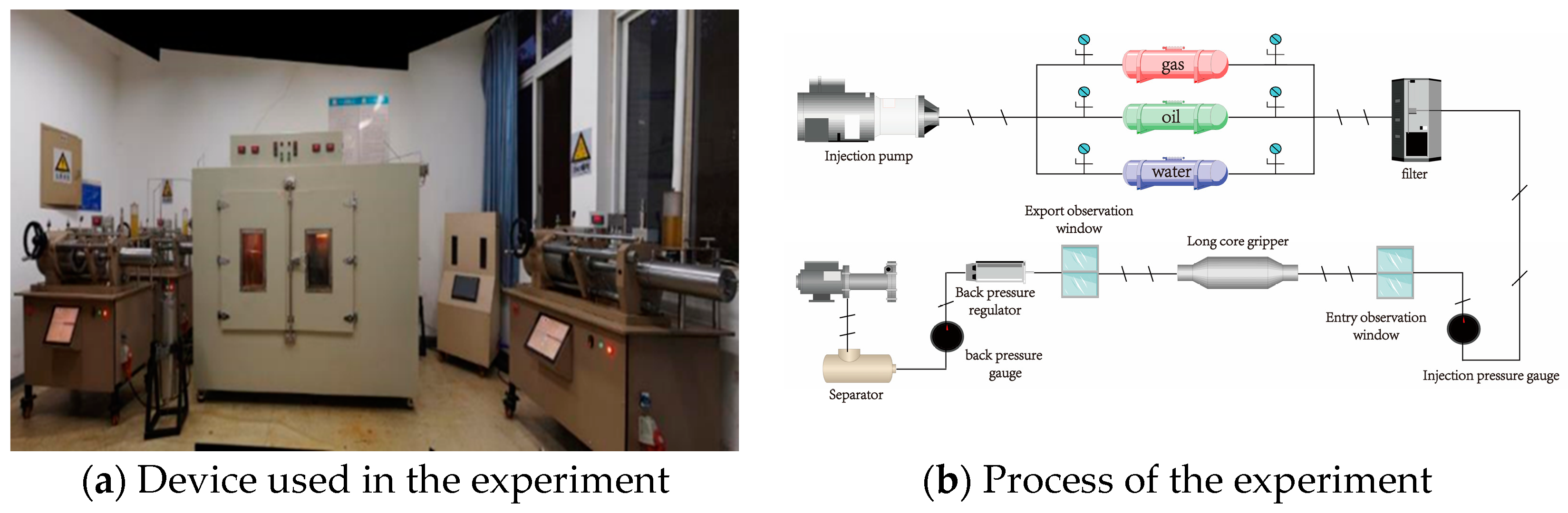
2.2. Experimental Setup and Process

The long core displacement experiment was conducted under set conditions of formation temperature and formation pressure and was divided into the following three stages: (1) the first depletion stage (to maximum retrograde condensate saturation, P s m ); (2) the synergistic gas drive stage; (3) the second depletion stage (to the abandoned pressure, P a ). The primary objective of this experiment was to assess the extent of reservoir heterogeneity and its impact on the effectiveness of gas injection. Additionally, for fractured reservoirs with high permeability, long core displacement experiments utilizing a gas flooding plus depletion development mode were conducted to further explore the impact of gas injection timing and method on enhancing condensate oil and gas recovery. The core displacement experimental apparatus and methodology are illustrated in Figure 1. The specific experimental procedures are as follows:
Experiment preparation. Initially, the core was saturated to the irreducible water saturation level of 34% ( S w c ). Each short core was aligned within the long core using the harmonic average method with filter paper inserted between each core to mitigate end effects. The long core was placed in the core holder and the initial pressure and temperature system ( P i , T i ) of the B6 gas reservoir were set up as specified in Table 1. Subsequently, the core was displaced at a slow speed using the prepared condensate gas sample, until the gas–oil ratio of the fluid at the core’s outlet matched that of the condensate gas.
First stage of depletion development. The pressure was gradually reduced from the formation pressure at a controlled rate, maintaining a constant pressure differential between the confining pressure and the internal pressure until it reached P s m . Throughout the stable period, system parameters such as gas volume, oil volume, inlet pressure, and outlet pressure were recorded at each test point. Subsequently, the experimental fluid was divided into gas and condensate oil samples using liquid nitrogen.
Synergistic gas drive stage. When the pressure decreased to P s m , injection gas was introduced continuously until no further increase in condensate recovery was observed. Throughout the experiment, outlet end parameters were recorded at intervals of 0.1 hydrocarbon pore volume (HCPV).
Second stage of depletion development. The pressure was gradually lowered at a controlled rate, maintaining a constant differential between the confining pressure and the internal pressure until it reached P a . At the end of each experimental set, the cores were cleaned with petroleum ether and ethanol, and subsequently dried with nitrogen in preparation for the next series of experiments.

3. Experiment Results

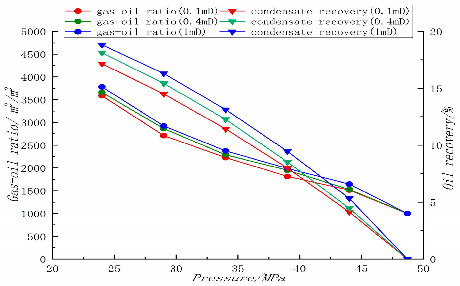
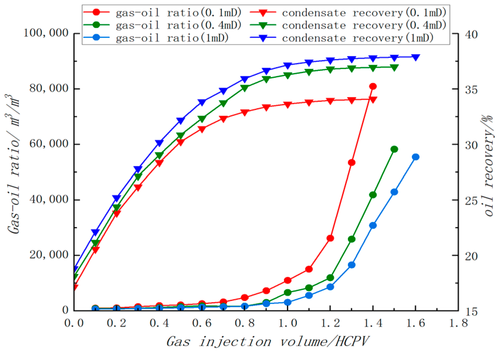
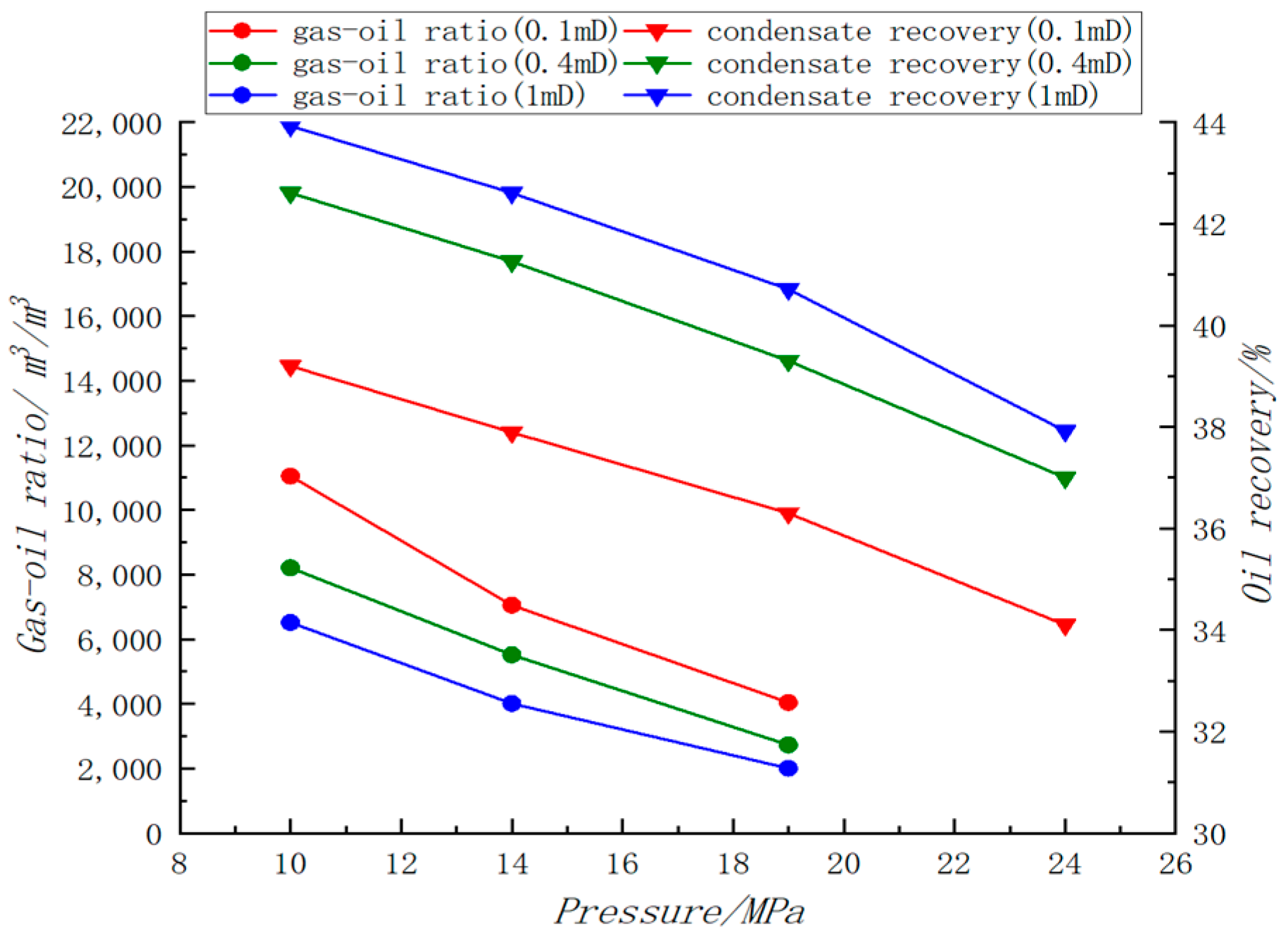
3.1. Effect of Matrix Permeability

A comprehensive comparison of three groups, each with different matrix permeability in gas injection experiments, and their respective gas–oil ratios and condensate oil recovery ratios, was carried out and is presented in Figure 2, Figure 3 and Figure 4. Figure 2 and Figure 4 illustrate changes in indicators under varying pressures during the first and second stages of depletion development. Meanwhile, Figure 3 displays the variations in the gas–oil ratio and condensate oil recovery during the gas injection period, recorded every 0.1 HPCV.
The experimental results indicate that total condensate oil recovery increases with matrix permeability, i.e., 39.20% at 0.1 mD, 42.61% at 0.4 mD, and 43.93% at 1 mD. This demonstrates a direct correlation between higher matrix permeability and increased oil recovery. In the initial stage of depletion development, as the result of retrograde condensation, the gas–oil ratio rises continuously with decreasing pressure. Condensate oil increasingly occupies the matrix pores and the gas–oil ratio rises more rapidly when the pressure falls below 30 MPa due to its poor mobility, and lower matrix permeability results in a lower gas–oil ratio. However, during gas injection development, lower matrix permeability leads to a higher production gas–oil ratio as is shown in Figure 3. The inflection point where the gas–oil ratio suddenly rises indicates the occurrence of gas channeling. Higher matrix permeability can delay the onset of gas channeling and improve the recovery rate during gas injection. For matrix porous medium flow, variations in permeability do not significantly affect development outcomes. However, in regions of the B6 buried hill condensate gas reservoir with varying fracture developments, the impact of main gas channeling on condensate oil recovery warrants further investigation.

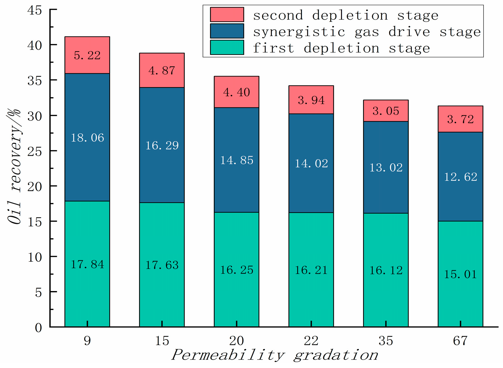
3.2. Effect of Permeability Gradation

Figure 5 displays a comparison of condensate oil recovery across three development stages under various permeability gradation conditions. It can be concluded that larger permeability differences result in lower overall recovery of condensate oil, and the presence of fractures tends to form dominant channels during the gas injection period. Significant amounts of condensate oil are retained in micropores and cannot be easily displaced by injection gas due to the weak supply capacity of the matrix, leading to decreased recovery rates. The study demonstrated that optimal permeability gradation for gas injection in fractured condensate gas reservoirs should be no higher than 15, with diminishing returns observed when exceeding 20. Consequently, gas injection development is more effective in areas with lower fracture development. In contrast, in areas with highly developed fractures, gas flooding is more prone to gas channeling, underscoring the urgency to optimize the development mode of the B6 gas reservoir.

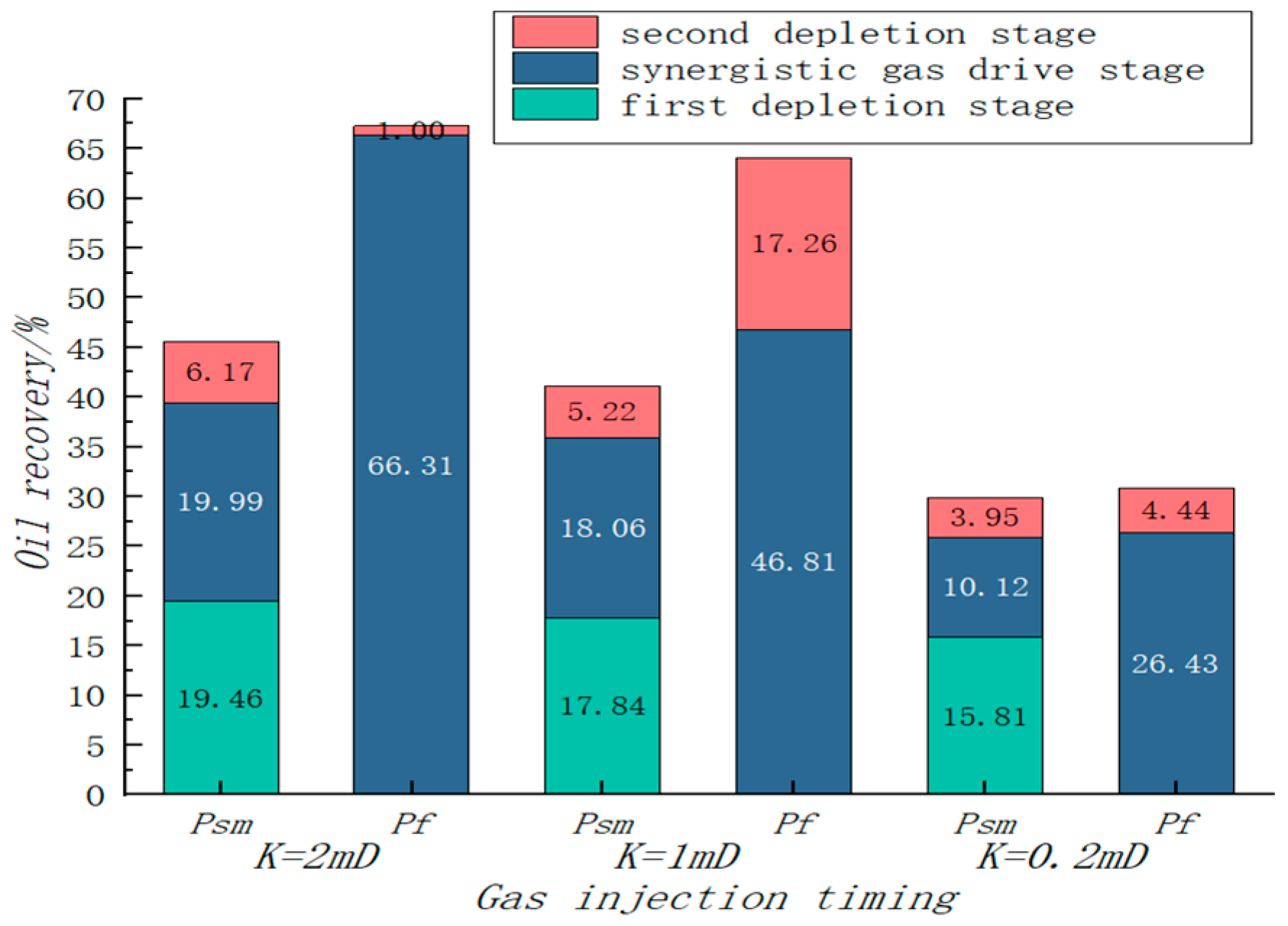
3.3. Effect of Gas Injection Timing

Figure 6 compares condensate oil recovery rates using two different gas injection timings—the original formation pressure and maximum retrograde condensate pressure—across various matrix permeabilities. The experimental results indicate that condensate oil recovery reaches 67.31% under original formation pressure conditions for a core with 1 mD matrix permeability, compared to only 45.62% under maximum retrograde condensate pressure conditions. Gas injection at the formation pressure more effectively improves condensate oil recovery compared to gas injection at the maximum retrograde condensate pressure. Analysis reveals that injecting gas above the dew point pressure prevents retrograde condensation, with all condensate oil components dissolved in the gas phase, facilitating large-scale production. At maximum retrograde condensation pressure, condensate oil is the most abundant, yet despite reverse evaporation effects, much remains unconverted to the gas phase and trapped within the reservoir. Oil displacement efficiency never reaches 100%, resulting in relatively low recovery rates. In cases of lower matrix permeability and significant permeability differences, the timing of gas injection minimally impacts recovery, necessitating optimization of the injection method.

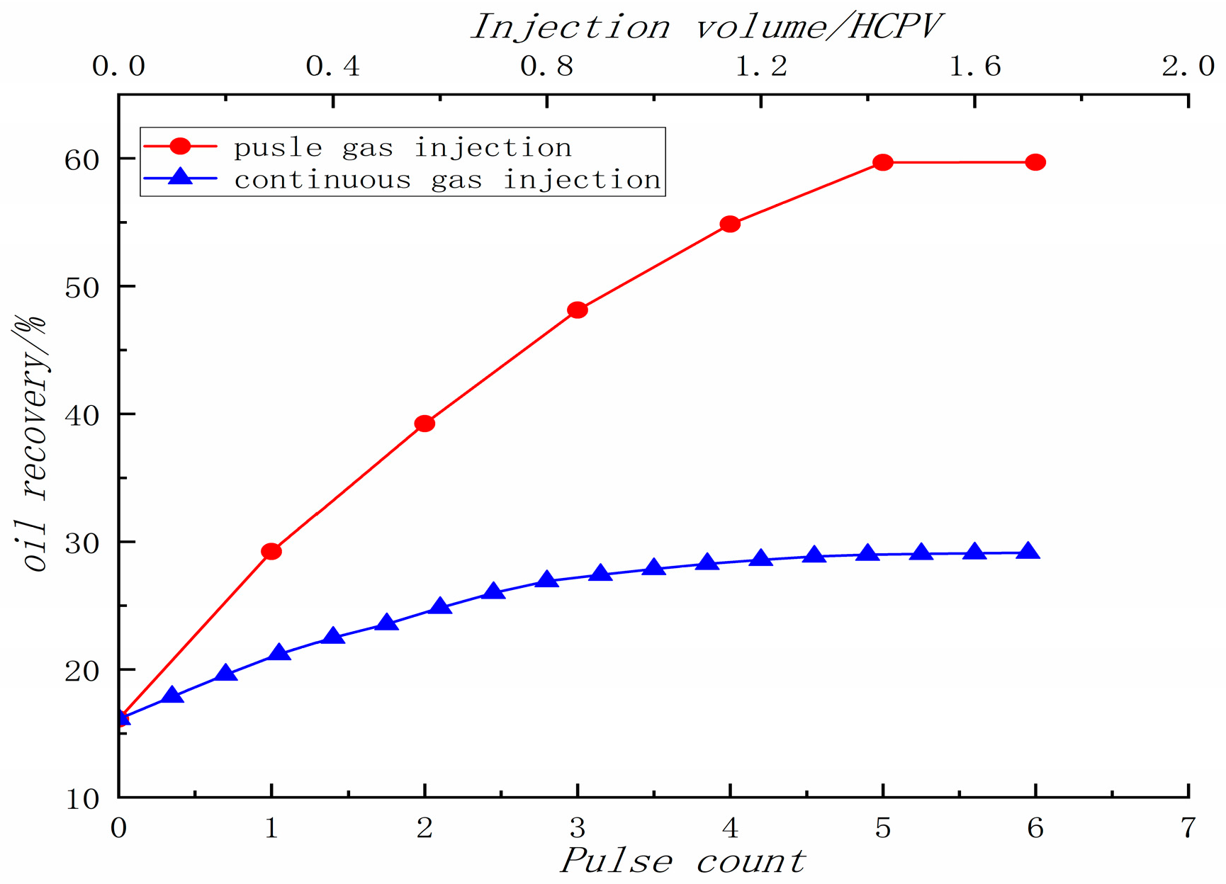
3.4. Effect of injection method

The experiment begins at a formation pressure of 48.7 MPa and continues until the pressure decreases to P s m (24 MPa). The outlet valve is then closed, and a specified amount of injection gas is introduced through the inlet until the formation pressure increases to the dew point pressure of 44.32 MPa. At this point, the inlet valve is closed to shut in the well. Once the core system’s pressure stabilizes, the outlet valve is reopened to reduce pressure from the dew point back to P s m . This cycle is repeated multiple times until there is no further increase in condensate oil recovery (an oil recovery difference of less than 0.05%). Subsequently, the core is depleted to the abandonment pressure of 10 MPa. The comparative results of two different gas injection methods (continuous gas injection and pulse gas injection) are presented in Figure 7.
Based on the experimental comparisons, it is evident that condensate oil recovery increases with the number of pulse gas injections in pulse injection mode. After the sixth pulse gas injection, condensate oil recovery reaches 59.70%, a 43.57% increase from the pre-injection level of 16.13%. In contrast, continuous gas injection yields only a 13.02% increase, clearly demonstrating the superior efficacy of pulse gas injection. The likely reason for this is that pulse gas injection raises the formation pressure, reducing gas–oil interfacial tension and bringing the gas–oil mixture closer to miscibility, thereby enhancing oil displacement efficiency. Additionally, the extended contact time between dry gas and condensate oil during well shut-in allows more condensate oil to revert to the gas phase, facilitating easier production. Furthermore, pulse gas injection is particularly effective in fractured reservoirs for minimizing gas channeling. Consequently, in zones of the B6 gas reservoir with significant permeability gradation, pulse gas injection is the recommended development method.

4. Field Application

4.1. Geological Characteristics of B6 Gas Reservoir

The B6 gas field features an anticline structure complicated by a series of small faults and is characterized by ultra-high condensate levels and a fracture-dominated geology. The gas reservoir is buried at depths ranging from 3870 to 4700 m, predominantly within the Neoarchean buried hill strata. The metamorphic buried hill reservoir is stratified from top to bottom into a weathering zone and an inner zone, influenced by the extent of fracturing and weathering. The weathering zone, which is the primary area for B6 gas reservoir development, is subdivided into the strongly weathered zone and the secondary weathering zone. Due to filling and compaction processes, the secondary weathering zone exhibits larger fracture widths and superior connectivity compared to the strongly weathered zone. Currently, nine wells in the B6 gas reservoir are undergoing depletion development, with gas injection modes optimized according to this well pattern. Experimental results indicate that optimal development outcomes are achieved when the permeability gradation is less than 15; accordingly, the field’s permeability range is defined using fracture and matrix permeability constraints, as illustrated in Figure 8.

4.2. Basic Parameters and Characterization of Oil–Gas Relative Permeability

The area around wells A1 and A2 exhibits low heterogeneity with a permeability gradation under 15, suggesting that gas injection development could theoretically yield superior outcomes. Based on these findings, a numerical simulation model of the B6 gas reservoir has been developed to optimize the gas injection network. In practice, associated gas reinjection is employed for gas injection development with a reinjection rate of 60%, tailored to the specific engineering conditions. Detailed reservoir and fluid physical parameters are presented in Table 3.
Currently, in the CH4/CO2/crude oil system, the conventional relative permeability treatment method assumes the two-phase fluid to be insoluble and incompressible, effectively ignoring the interactions between oil and gas. However, this overlooks the significant solubility of CO2 in crude oil. Zhao et al. [29] asserts that the viscosity of the crude oil sharply decreases, leading to a narrowing of the oil–gas two-phase region, a significant increase in oil-phase permeability and a slight reduction in residual oil saturation when considering the dissolution effects of CO2. Moreover, traditional experimental methods often use dead oil or simulated oil rather than actual crude oil samples, which fails to capture the real interactions between crude oil and CO2, leading to deviations in results. In this section, we introduce a relative permeability characterization method that accounts for dissolution, described as follows:
p g x = Q g μ g A K K r g 1 λ b g | P | + λ b g λ a g
Q g = A u f g
where p represents pressure, MPa; P represents pressure gradient between the ends of the core, MPa/m; x represents flow distance along the displacement direction, m; Q represents flow rate, m3/s; u represents flow velocity, m/s; A represents core cross-sectional area, m2; f represents fractional flow, dimensionless; K represents absolute permeability, mD; Kr represents relative permeability, dimensionless; μ represents viscosity, mPa·s;   λ a ,   λ b represents threshold pressure gradient and pseudo threshold pressure gradient, respectively; subscripts g, represent the gas phase.
The equation of CO2 isosaturation movement can be expressed as follows:
x = f g S g φ A 0 t Q ( t ) d t
For the end of the core outlet,
L = f g S g e φ A 0 t Q ( t ) d t
Dimensionless injection quantity can be expressed as follows:
V ¯ ( t ) = 0 t Q ( t ) d t φ A L = 1 f g S g e
where   S g represents gas saturation, which is dimensionless;   S g e represents gas saturation at the core outlet, which is dimensionless; φ represents porosity, which is also dimensionless.
The pressure difference between both ends of the core can be expressed as follows:
Δ p = 0 L p x d x
By substituting Equations (1)–(5) into the pressure difference equation, relative permeability of the oil phase can be expressed as Equation (7).
K r o ( S g e ) = f 0 S g e 1 λ b | P | + λ b λ a d 1 V ¯ ( t ) d 1 V ¯ ( t ) I
The oil and gas flow rate at the outlet of the core is proportional to the fractional flow parameters.
Q g Q o = 1 f o f o
The relative permeability of the oil phase can be calculated by inserting the flow rate equation into Equation (8).
K r g ( S g e ) = 1 f o f o K r o S g e μ g μ o × 1 λ b o | P | + λ b o λ a o 1 λ b g | P | + λ b g λ a g
In addition, the dissolution of CO2 can be reflected by the viscosity reduction effect through the Arrhenius equation.
μ m i x = μ o x 1 μ g x 2
Figure 9 presents the fitted oil production rate curve for well A4. It is evident that the predicted oil production rate of the traditional model, which did not account for CO2 dissolution in the oil phase, is lower than the actual production data. The prediction results of the new model demonstrate that CO2 increases the mobility of the oil phase, thus providing a better match with the actual field data.

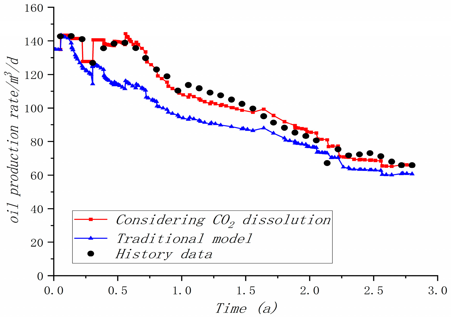
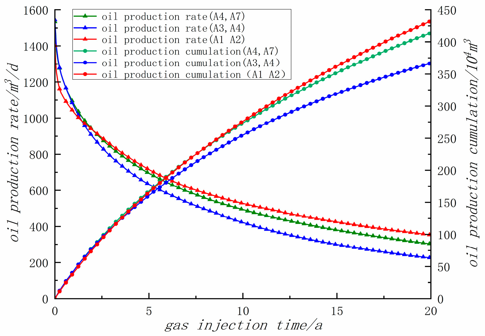
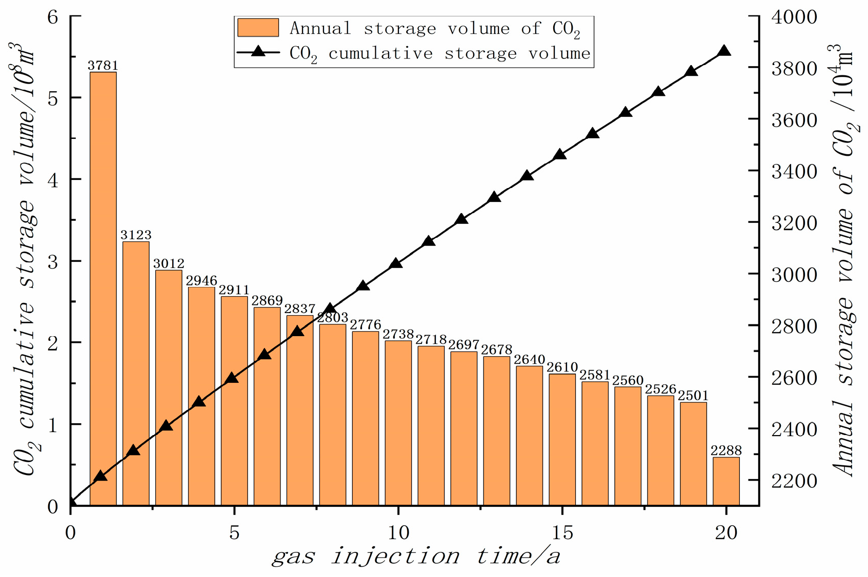
4.3. Prediction of Gas Injection Development Effect

The A1 and A2 wells are located in an area of low permeability gradation, resulting in minimal heterogeneity around the injectors and uniform gas propulsion. This configuration effectively supplies energy and prevents gas channeling. Numerical simulations indicate that oil production from A1 and A2 is initially lower than other wells due to limited fracture development. However, as gas channeling begins to impact other wells, these two maintain higher cumulative oil production, aligning with the experimental results shown in Figure 10. In contrast, the strong heterogeneity of the reservoir surrounding wells A3 and A4 facilitates rapid gas channeling, resulting in a final cumulative oil production of less than 66 thousand cubic meters over a two-year injection period, markedly lower than that achieved by A1 and A2.
Circulating gas injection not only enhances the recovery of condensate gas reservoirs but also effectively enables CO2 storage. During the gas injection development at the B6 gas reservoir, the stored volume of CO2 amounted to 5.56 million cubic meters, averaging 0.62 million cubic meters per well, as illustrated in Figure 11.
This study explores the gas injection development limits of the B6 fractured condensate gas reservoir using both physical simulation experiments and numerical simulation. However, there is a lack of field dynamic data for validation due to the short gas injection implementation time. Future efforts will concentrate on improving the characterization of heterogeneity in fractured reservoirs, continuously monitoring production dynamics during the gas injection development phase and evaluating the synergistic effects of CH4/CO2 synergistic displacement.

5. Conclusions

(1)
For the first time, an experimental study of gas injection with varying permeability gradations was conducted. The results indicate that fractures readily form dominant channels for gas channeling. The findings demonstrate that larger permeability gradations lead to lower recovery rates of condensate oil. Optimal development outcomes are achieved when permeability gradation is maintained below 15.
(2)
Higher matrix permeability correlates with increased recovery of condensate oil. Earlier gas injection significantly enhances these recovery rates. Additionally, smaller permeability gradations result in greater increases in condensate oil recovery. Pulse gas injection markedly improves oil recovery in buried hill reservoirs.
(3)
In the B6 condensate gas field, maintaining formation pressure via gas injection is recommended, particularly in the weathering zone with weak fracture connectivity. Wells A1 and A2 were recommended early gas injection to mitigate retrograde condensation through numerical simulation.

Author Contributions

Conceptualization, C.Y.; Methodology, C.Y. and J.W.; Formal analysis, H.W. and Y.J.; Visualization, H.W.; Validation, Y.J.; Writing—original draft, C.Y., Q.Z. and H.T.; Writing—review and editing, X.S. and P.G. All authors have read and agreed to the published version of the manuscript.

Funding

The authors would like to thank the National Science and Technology Major Project (2016ZX05058-001), CNOOC Co., Ltd. Major Project (CNOOC-KJ135 ZDXM36 TJ03TJ-GD2020-01 and KJGG-2022-12-CCUS-0202) and CNOOC Co., Ltd. Comprehensive Scientific Research Project (CNOOC-KJZH-2024-2205).

Data Availability Statement

The data presented in this study are available on request from the corresponding author. The data are not publicly available due to privacy and legal reasons.

Conflicts of Interest

Authors Chenxu Yang, Jintao Wu, Haojun Wu, Yong Jiang, Xinfei Song, Qixuan Zhang were employed by the company Tianjin Branch of CNOOC Ltd. The remaining authors declare that the research was conducted in the absence of any commercial or financial relationships that could be construed as a potential conflict of interest. The authors declare that this study received funding from CNOOC Co., Ltd. The funder was not involved in the study design, collection, analysis, interpretation of data, the writing of this article or the decision to submit it for publication.

References

  1. Guo, P.; Wang, J.; Liu, W.; Du, J.F.; Wang, Z.H. Dynamic Experiment Study on Depletion Development of Condensate Gas Reservoir with Fracture and Cave. Oil Drill. Prod. Technol. 2013, 35, 67–70. [Google Scholar]
  2. Guo, P.; Liu, H.; Wang, C.X.; Du, J.F.; Fan, B.C.; Jing, M.Q.; Wang, Z.H.; Deng, Z.L.; Zhan, S.Y. The Determination of Phase Behavior Properties of High-Temperature High-Pressure and Rich Condensate Gases. Fuel 2020, 280, 118568. [Google Scholar] [CrossRef]
  3. Najafi-Marghmaleki, A.; Tatar, A.; Barati-Harooni, A.; Arabloo, M.; Rafiee-Taghanaki, S.; Mohammadi, A.H. Reliable Modeling of Constant Volume Depletion (CVD) Behaviors in Gas Condensate Reservoirs. Fuel 2018, 231, 146–156. [Google Scholar] [CrossRef]
  4. Arabloo, M.; Heidari Sureshjani, M.; Gerami, S. A New Approach for Analysis of Production Data from Constant Production Rate Wells in Gas Condensate Reservoirs. J. Nat. Gas Sci. Eng. 2014, 21, 725–731. [Google Scholar] [CrossRef]
  5. Bennion, D.B.; Thomas, F.B.; Schulmeister, B. Retrograde Condensate Dropout Phenomena in Rich Gas Reservoirs—Impact on Recoverable Reserves, Permeability, Diagnosis, and Stimulation Techniques. J. Can. Pet. Technol. 2001, 40, 5–8. [Google Scholar] [CrossRef]
  6. Wu, Y.M.; Yao, K.; Liu, Y.; Li, X.Y.; Wu, M.M.; Cheng, R.H.; Wang, B. Experimental Study on Enhanced Condensate Recovery by Gas Injection in Yaha Condensate Gas Reservoir. Geofluids 2021, 2021, 7698970. [Google Scholar] [CrossRef]
  7. Sanger, P.; Hagoort, J. Recovery of Gas-Condensate by Nitrogen Injection Compared with Methane Injection. SPE J. 1988, 3, 26–33. [Google Scholar] [CrossRef]
  8. Guo, P.; Jing, S.S.; Peng, C.Z. Technology and Countermeasures for Gas Recovery Enhancement. Nat. Gas Ind. 2014, 34, 48–55. [Google Scholar]
  9. Tang, Y.; Long, K.J.; Wang, J.M.; Xu, H.C.; Wang, Y.; He, Y.W.; Shi, L.; Zhu, H.Y. Change of Phase State During Multi-Cycle Injection and Production Process of Condensate Gas Reservoir Based Underground Gas Storage. Pet. Explor. Dev. 2021, 48, 395–406. [Google Scholar] [CrossRef]
  10. Taheri, A.; Hoier, L.; Torsaeter, O. Miscible and Immiscible Gas Injection for Enhancing of Condensate Recovery in Fractured Gas Condensate Reservoirs. Presented at the EAGE Annual Conference & Exhibition Incorporating SPE Europec, London, UK, 10–13 June 2013. SPE-164934-MS. [Google Scholar]
  11. Jiang, T.W. Study on the Supercritical Phase Behavior of Yaha Condensate Gas Reservoir in the Tarim Basin. Petroleum 2021, 9, 390–394. [Google Scholar] [CrossRef]
  12. Liu, F.Y.; Ellett, K.; Xiao, Y.T.; Rupp, J.A. Assessing the Feasibility of CO2 Storage in the New Albany Shale (Devonian-Mississippian) with Potential Enhanced Gas Recovery Using Reservoir Simulation. International J. Greenh. Gas Control 2013, 17, 111–126. [Google Scholar] [CrossRef]
  13. Hannis, S.; Lu, J.; Chadwick, A.; Hovorka, S.; Kirk, K.; Romanak, K.; Pearce, J. CO2 Storage in Depleted or Depleting Oil and Gas Fields: What Can We Learn from Existing Projects? Energy Procedia 2017, 114, 5680–5690. [Google Scholar] [CrossRef]
  14. Underschultz, J.; Boreham, C.; Dance, T.; Stalker, L.; Freifeld, B.; Kirste, D.; Ennis-King, J. CO2 Storage in a Depleted Gas Field: An Overview of the CO2CRC Otway Project and Initial Results. Int. J. Greenh. Gas Control 2011, 5, 922–932. [Google Scholar] [CrossRef]
  15. Zangeneh, H.; Jamshidi, S.; Soltanieh, M. Coupled Optimization of Enhanced Gas Recovery and Carbon Dioxide Sequestration in Natural Gas Reservoirs: Case Study in a Real Gas Field in the South of Iran. Int. J. Greenh. Gas Control 2013, 17, 515–522. [Google Scholar] [CrossRef]
  16. Du, F.; Nojabaei, B. A Review of Gas Injection in Shale Reservoirs: Enhanced Oil/Gas Recovery Approaches and Greenhouse Gas Control. Energies 2019, 12, 2355. [Google Scholar] [CrossRef]
  17. Kumar, N.; Sampaio, M.A.; Ojha, K.; Hoteit, H.; Mandal, A. Fundamental Aspects, Mechanisms, and Emerging Possibilities of CO2 Miscible Flooding in Enhanced Oil Recovery: A Review. Fuel 2022, 330, 125633. [Google Scholar] [CrossRef]
  18. Shtepani, E. CO2 Sequestration in Depleted Gas/Condensate Reservoirs. Paper presented at the SPE Annual Technical Conference and Exhibition, San Antonio, TX, USA, 24–27 September 2006. [Google Scholar]
  19. Shen, C.H.; Hsieh, B.-Z.; Tseng, C.C. Case Study of CO2-IGR and Storage in a Nearly Depleted Gas-Condensate Reservoir in Taiwan. Energy Procedia 2014, 63, 7740–7749. [Google Scholar] [CrossRef]
  20. Scanziani, A.; Singh, K.; Menke, H.; Bijeljic, B.; Blunt, M.J. Dynamics of Enhanced Gas Trapping Applied to CO2 Storage in the Presence of Oil Using Synchrotron X-ray Micro Tomography. Appl. Energy 2020, 259, 114136. [Google Scholar] [CrossRef]
  21. Narinesingh, J.; Alexander, D. CO2 Enhanced Gas Recovery and Geologic Sequestration in Condensate Reservoir: A Simulation Study of the Effects of Injection Pressure on Condensate Recovery from Reservoir and CO2 Storage Efficiency. Energy Procedia 2014, 63, 3107–3115. [Google Scholar] [CrossRef]
  22. Yuan, C.; Zhang, Z.; Liu, K. Assessment of the Recovery and Front Contrast of CO2 EOR and Sequestration in a New Gas Condensate Reservoir by Compositional Simulation and Seismic Modeling. Fuel 2015, 142, 81–86. [Google Scholar] [CrossRef]
  23. Sayed, M.A.; Al-Muntasheri, G.A. Mitigation of the Effects of Condensate Banking: A Critical Review. SPE Prod. Oper. 2016, 31, 85–102. [Google Scholar] [CrossRef]
  24. Chen, C.; Balhoff, M.; Mohanty, K.K. Effect of Reservoir Heterogeneity on Primary Recovery and CO2 Huff ‘n’ Puff Recovery in Shale-Oil Reservoirs. SPE Reserv. Eval. Eng. 2014, 17, 404–413. [Google Scholar] [CrossRef]
  25. Al-Abri, A.; Sidiq, H.; Amin, R. Mobility Ratio, Relative Permeability and Sweep Efficiency of Supercritical CO2 and Methane Injection to Enhance Natural Gas and Condensate Recovery: Coreflooding Experimentation. J. Nat. Gas Sci. Eng. 2012, 9, 166–171. [Google Scholar] [CrossRef]
  26. Qu, M.; Hou, J.; Wen, Y.; Liang, T. Nitrogen gas channeling characteristics in fracture-vuggy carbonate reservoirs. J. Pet. Sci. Eng. 2020, 186, 106723. [Google Scholar] [CrossRef]
  27. Tran, S.; Yassin, M.R.; Eghbali, S.; Doranehgard, M.H.; Dehghanpour, H. Quantifying oil-recovery mechanisms during natural-gas huff ‘n’ puff experiments on ultratight core plugs. SPE J. 2021, 26, 498–514. [Google Scholar] [CrossRef]
  28. Chen, X.; Mohanty, K.K. Pore-Scale Mechanisms of Immiscible and Miscible Gas Injection in Fractured Carbonates. Fuel 2020, 275, 117909. [Google Scholar] [CrossRef]
  29. Zhao, S.X.; Wang, R.; Lv, C.Y.; Lun, Z.M.; Zhou, Y. Influences of the dissolution on the relative permeabilities for CO2 flooded low-permeability oil reservoirs. Pet. Geol. Oilfield Dev. Daqing 2016, 35, 126–129. (In Chinese) [Google Scholar]
Figure 1. Core displacement experimental device and process.
Energies 17 03326 g001
Figure 2. Comparison of gas–oil ratio and condensate oil recovery under different matrix permeability in the first depletion stage.
Energies 17 03326 g002
Figure 3. Comparison of gas–oil ratio and condensate oil recovery under different matrix permeability in the synergistic gas drive stage.
Energies 17 03326 g003
Figure 4. Comparison of gas–oil ratio and condensate oil recovery under different matrix permeability in the second depletion stage.
Energies 17 03326 g004
Figure 5. Comparison of condensate oil recovery with different levels of permeability gradation.
Energies 17 03326 g005
Figure 6. Comparison of condensate oil recovery with different gas injection timings.
Energies 17 03326 g006
Figure 7. Comparison of condensate oil recovery with different gas injection methods.
Energies 17 03326 g007
Figure 8. Distribution field of permeability gradation in B6 condensate gas reservoir.
Energies 17 03326 g008
Figure 9. History match and model comparison of oil production rate of well A4.
Energies 17 03326 g009
Figure 10. Numerical simulation results of gas injection in different well locations of B6 condensate gas reservoir.
Energies 17 03326 g010
Figure 11. CO2 storage index of gas injection development in B6 condensate gas reservoir.
Energies 17 03326 g011
Table 1. Main parameters of B6 gas reservoir.
ParametersValue
Formation temperature, °C172
Initial formation pressure, MPa48.7
Dew point pressure, MPa44.3
Maximum retrograde condensation pressure, MPa24
Condensate density, g/cm30.799
Gas–oil radio, m3/m31000
Table 2. Permeability parameters of long cores.
NoCore Length
(m)
Matrix Permeability
(mD)
Fracture Permeability
(mD)
Permeability Gradation
199.730.15-1
289.640.1610.1167
389.880.163.2620
499.680.41-1
599.700.4114.2735
689.950.416.215
794.661.47-1
889.751.0222.4122
989.791.019.59
Table 3. Reservoir and fluid parameters of numerical simulation model.
ParametersValue
Fracture density of strong weathering zone, /m6.78
Fracture density of secondary weathering zone, /m4.22
Average porosity of strong weathering zone, %4.9
Average porosity of strong weathering zone, %3.6
CO2 content, %10
Disclaimer/Publisher’s Note: The statements, opinions and data contained in all publications are solely those of the individual author(s) and contributor(s) and not of MDPI and/or the editor(s). MDPI and/or the editor(s) disclaim responsibility for any injury to people or property resulting from any ideas, methods, instructions or products referred to in the content.

