Abstract
This paper reviews alarm processing methods in electrical power systems, focusing on evolving strategies beyond traditional fault analysis to accommodate modern grid complexities. Historically, alarm processing has predominantly aimed at fault analysis, increasingly merging with technological advances in communication and computing. However, it still needs to fully meet the challenges posed by the dynamic characteristics of modern power systems. This review points out certain inadequacies in current practices, notably their limited adaptation to new grid conditions. The authors propose a novel generation of alarm processing methodologies designed for future grids, emphasizing managing rare events and enhancing operator decision-making through advanced anomaly detection and explainable artificial intelligence. This synthesis presents a prospective direction for future research and applications in alarm processing, advocating for methodologies better suited to supporting system operators amidst technological advancements.
1. Introduction
The power system is crucial for delivering electrical energy from generation facilities to customers in real time. The rapid growth in demand for electricity has led to the expansion of both generation and transmission/distribution facilities, making the power system more complex [1]. Moreover, due to the synchronized nature of the power system, a sudden change in some small local area can ripple through and impact the entire power system [2]. For example, a decrease in output from a generating facility or a disruption in a transmission line can lead to localized power outages and broader system stability issues due to fluctuations of the synchronous frequency. Without prompt and effective intervention, such problems can collapse system-wide, causing large-scale blackouts and significant social and economic losses [3,4].
In response to these challenges, system developers have introduced operational aids like advanced monitoring systems to enhance the effective management of grids. However, this has led to an increase in the information the system operators must handle. Combined with the growing complexity of modern power systems [5,6], it has significantly heightened the stress on operators. Specifically, the burden on operators to manage the vast amount of data directly results from an environment that supports diverse system data acquisition and large-scale data processing [7]. To address these issues, developing sophisticated alarm processing techniques has become essential. These techniques help operators maintain situational awareness during alarm floods, that is, large-scale alarm events.
The primary purpose of alarm processing is to support system operators. There have been many research studies on alarm processing in which, in the narrowest sense, alarm processing methods focus on supporting the operators by removing, cleaning, transforming, or visualizing the alarm data rather than deriving new insights from said data. However, more comprehensively, alarm processing involves inferring meaningful information from the data, such as finding the location and the cause of a fault or identifying malfunctions in system devices, information which is then delivered to the system operator. Thus, the outcomes of alarm processing can vary significantly depending on the designer’s preferences and objectives, the types of data utilized, and the methodologies applied.
Among the various methods to assist system operators, most alarm processing research predominantly focuses on fault analysis, wherein the fault causes and locations are determined based on the behavioral states of numerous protective devices and fault indicators in power systems. Fault analysis involves constructing an alarm scenario that anticipates the system’s response to a specific fault and then comparing the actual alarm occurrences against the scenario to extract meaningful information. Knowledge-based and data-based models have been employed to create scenarios. The effectiveness of these models is assessed based on their ability to identify the causes of failures accurately.
It is contended that the prevalent bias toward fault analysis in alarm processing research results from adherence to historical methodologies despite significant changes in system environments and technological advancements. Information once crucial for assisting operators in relatively simple system environments has become less relevant in today’s complex operational settings. For example, in modern power systems equipped with various automation technologies, information about situations that can be resolved automatically without operator intervention is no longer necessary. Given these changes, reassessing the operator’s role in future system environments is essential, as is making adjustments in the direction of alarm processing research.
This paper analyzes existing alarm processing methods, outlines their limitations, and proposes a new direction. As automation technology advances, the role of the system operator is expected to diminish, while systems’ complexity will likely increase. Consequently, current methodologies will become less effective for alarm processing. Additionally, this paper examines the type of information that should be provided by effective alarm processing in the evolving grid environment, with a particular focus on the potential advantages of AI-based methodologies.
The aim of this review paper is to address the following objectives:
- Overview of Methods: Present an overview of alarm processing methods that utilize monitoring information from power systems, based on an analysis of previously published related papers.
- Analysis of Limitations: Analyze related papers to identify the problems and limitations of existing alarm processing definitions, with particular attention to issues of the potential for objective bias.
- Future Research Directions: Outline the research directions in which existing alarm processing methodologies should be directed to adapt to future changes in the power system.
The articles referenced in this paper were selected using a structured research methodology. The purpose of this process was to ensure a comprehensive and rigorous review of the literature. A comprehensive search was conducted using specific criteria in major academic databases, including Scopus and Web of Science. In Scopus, articles were identified through a search of the database using the terms “power”, “system”, “alarm”, and “processing” within the titles and abstracts. The search was conducted to identify articles within categories related to energy and engineering. Similarly, the search on Web of Science included these terms with the additional filtering of articles under the engineering, electrical, and electronic categories. This process yielded 469 articles, which were subsequently subjected to a rigorous screening process based on the four established criteria below. This process was undertaken to ensure the review’s relevance and rigor.
- Only papers related to alarm systems applied to power grid systems were included.
- Literature about the communication aspects of alarm systems was excluded.
- Literature about the hardware design of alarm systems was excluded.
- Duplicates were removed from the collection.
This paper is organized as follows: Section 2 describes the characteristics of typical alarms in industry. Section 3 discusses alarm processing in power systems, including the system information commonly utilized in this process. Section 4 classifies and analyzes existing research in the field of alarm processing. Section 5 examines the evolution of alarm processing methods, noting the current focus on fault analysis, and suggests future directions for changing grid environments. Finally, Section 6 provides a summary of the findings and conclusions of this thesis.
2. Understanding Alarm Systems in Industrial Settings
2.1. Fundamentals of Alarms in Industry
In the industrial sector, an alarm is typically defined as a visual and audible means of alerting operators to malfunctions, process deviations, and abnormal conditions that require a response [8,9]. Essentially, the primary function of an alarm is to notify operators of discrepancies within the management system. Upon receiving this notification, operators are prompted to assess the system’s current status and take the necessary actions to correct the abnormal condition.
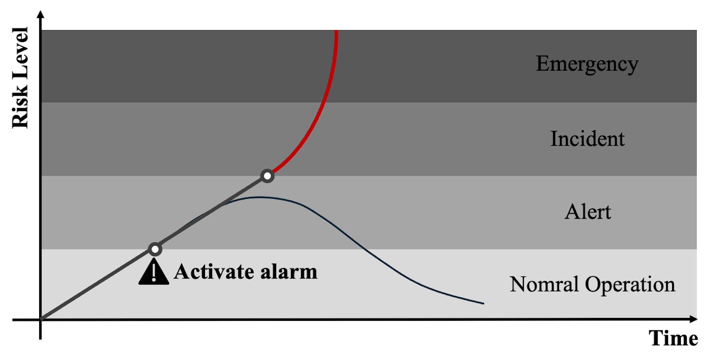
Figure 1 illustrates the critical role of alarms in managing system anomalies. If an alarm is activated correctly, then the system can quickly return to normal through operator intervention. Conversely, the chances of restoring normalcy are significantly reduced if the operator’s response is inadequate or if an alarm is triggered too late—when the system is on the verge of collapse. Thus, effectively configured alarms are essential, as they empower operators to address issues promptly and mitigate the risk of significant damage to property and lives.
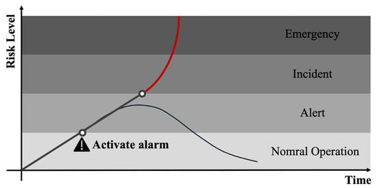
Figure 1.
Layers of protection based on [9].
The fundamental behavioral condition for triggering an alarm is when a measured value within the system deviates beyond a user-defined threshold. This condition is depicted in Equation (1), assuming the alarm state is represented as ‘1’ when the alarm triggers at a specific time t and ‘0’ otherwise. Moreover, the alarm is activated when the measured value exceeds the set point and reverts to ‘0’ when the value is below this threshold. This mechanism provides the operator with intuitive information by directly indicating the anomaly’s location.
2.2. Critical Role of Alarm Systems in Industrial Safety
For systems of modest size, the setpoint setting method generally suffices. Historically, systems were monitored using visual and audible alarms, commonly known as ‘light boxes’ [10]. However, as the size and complexity of management systems increase, so too does the number of measuring devices needed to assess system status, leading to a proportional rise in the number of alarms communicated to the operator. This increase can lead to an alarm flood situation if not properly managed [11,12,13]. Defined as a scenario in which an overwhelming number of alarms inundate the operator during system issues, this can significantly impair decision-making, potentially causing severe system accidents [14,15].
Historical records have documented significant incidents that underscore the importance of effective alarm systems [16,17,18]. One notable example is an incident in which a system exploded after receiving 275 alarms within 11 minutes. Another example is the BP Texas City incident, in which the absence of crucial alarms used to monitor system status led to inadequate operator response, culminating in a fire that caused loss of life. Such events highlight the critical role of alarm systems in operational safety, necessitating the precise identification of core information conveyed by alarms and meticulous recording of alarm changes [8,19]. Ultimately, the primary objective of alarm processing is to efficiently manage a substantial number of alarms and ensure they are communicated to the operator effectively [20,21,22].
2.3. Key Criteria for Efficient Alarm Processing
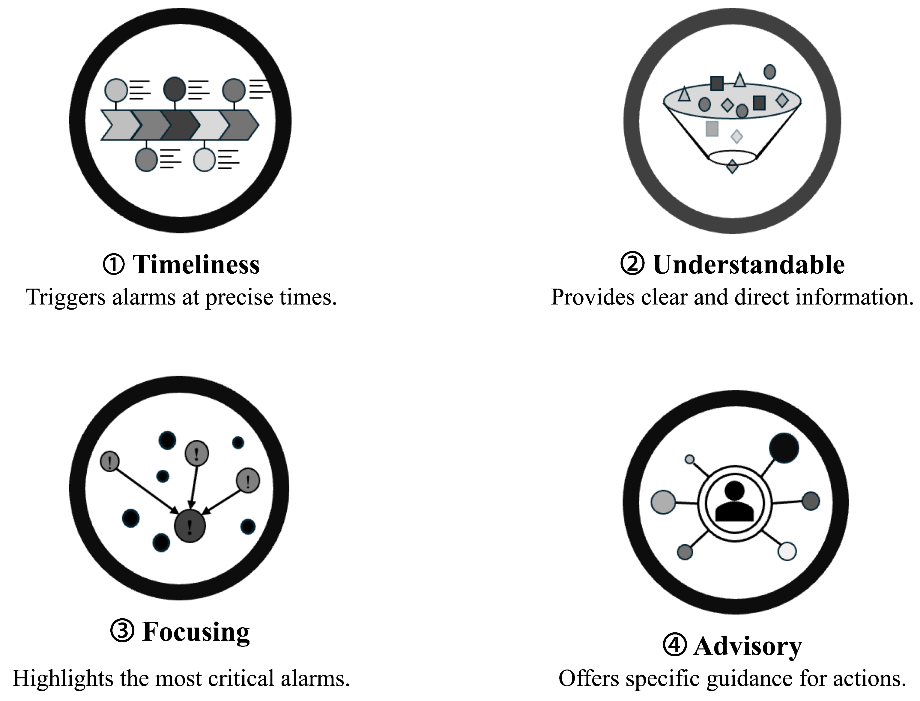
Then, what criteria should be satisfied by the appropriate alarm processing required to respond to such abnormal system situations? The literature has proposed that the role and characteristics of alarms be communicated from the alarm system to the operator as criteria for appropriate alarm processing [17,23,24]. The alarm processing functions proposed in the literature can be summarized by the four representations in Figure 2 below.
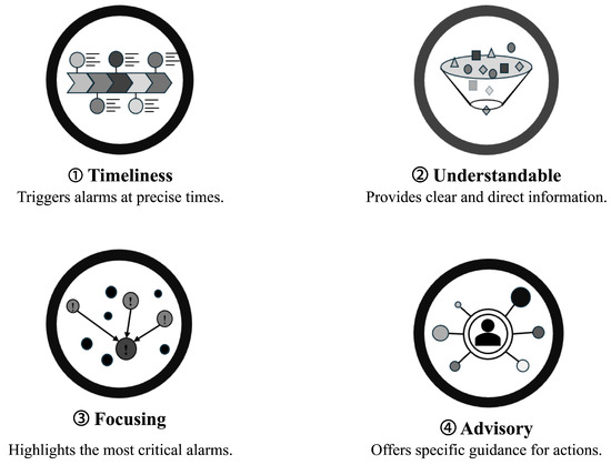
Figure 2.
Summary of key elements for effective alarm management.
Timeliness is defined as preventing system alarms from being raised prematurely or delayed from the time of a system state change. In some systems, a time log is recorded, and the alarms are raised. If this time log is faulty and the order of the alarms is changed, it can cause significant issues in recognizing system faults. Understandability is the ability of the operator to clearly understand a particular condition from a single piece of alarm information. An example of a violation of this is when specific alarms are toggling. This occurs when the same alarm is repeatedly communicated to the operator, causing multiple alarms to have the same meaning. Focusing provides indirect alarm summary information by prioritizing the alarms raised by the system. Its purpose is to draw the operator’s attention to alarms that are of high importance, for example, highlighting the location of a fault during a fault situation. An advisory alarm should be able to guide the operator’s behavior. For example, an alarm indicating that an oil leak has occurred in a plant can directly guide checking for an oil leak. However, an alarm indicating a temperature rise in a transformer caused by a leak would not directly support action because there could be multiple causes.
In summary of Section 2, an effectively designed alarm system enables low operating costs, high quality, and ultimately safe system operation. Therefore, there is a pressing need for research and development in alarm processing systems, focusing on communicating system status to system operators. In particular, research on alarm processing methods for power systems is of paramount importance, given the significant impact that power systems have on the entire industry and the necessity for high reliability and stability.
3. Background for the Alarm Processing of Power Systems
3.1. The Role of Alarm Processing as a Subsystem in Power System Management
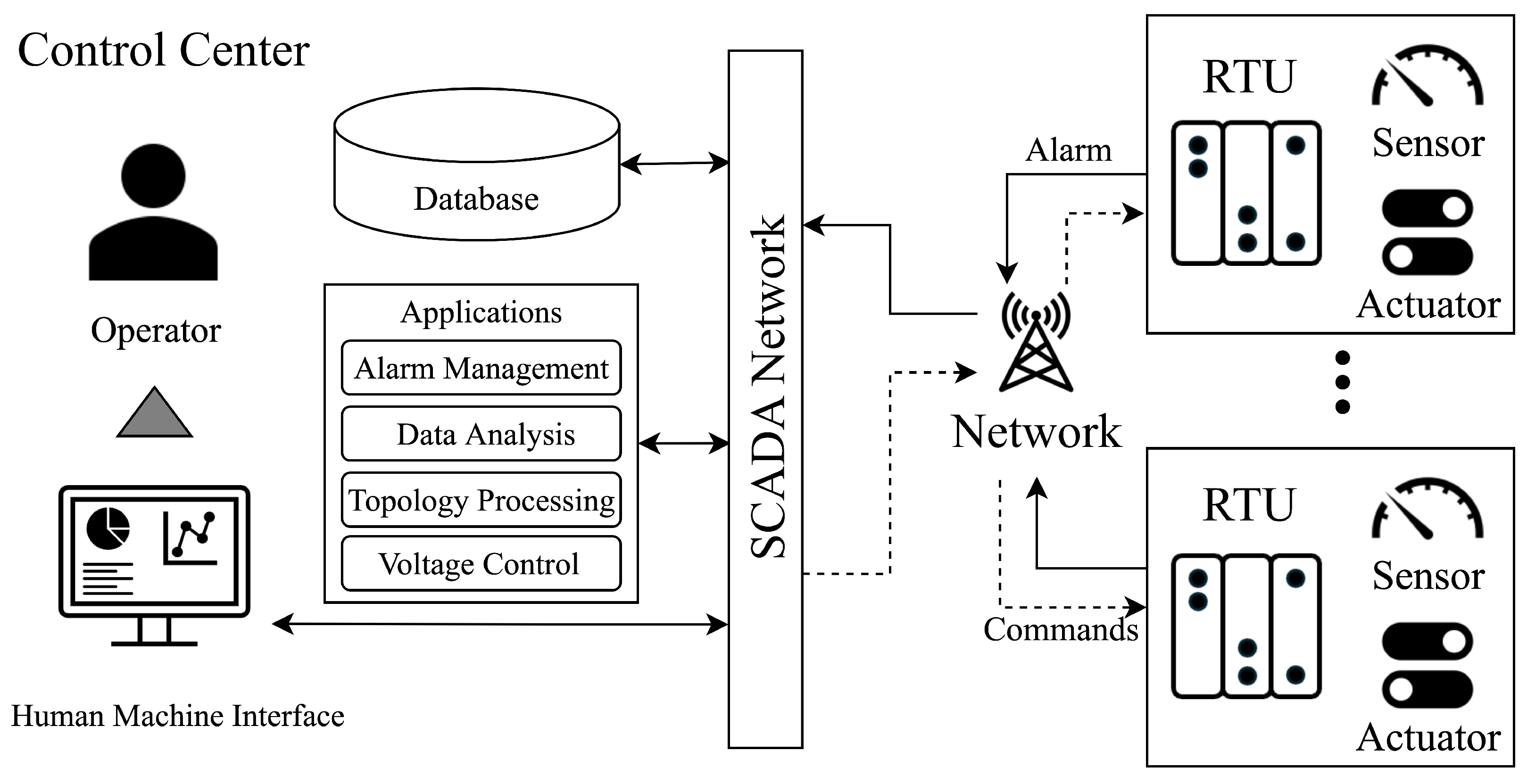
Figure 3 illustrates the configuration of devices in power system management, emphasizing the function of the alarm processing system. Remote terminal units (RTUs) are situated within the local network, where they gather analog measurements from sensors, operational signals from protection devices, and alarms generated by local processes. This information is conveyed to the supervisory control and data acquisition (SCADA) system, which is stored and managed in an internal database.
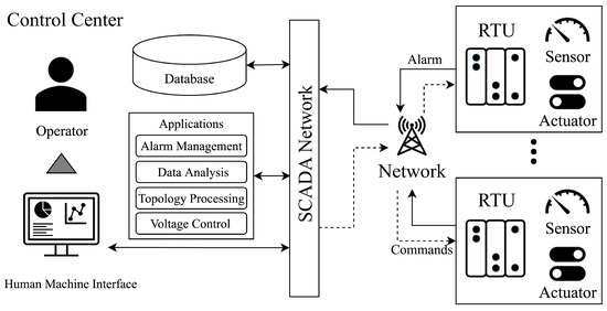
Figure 3.
SCADA and RTU architecture.
This information is of critical importance for the execution of system applications such as fault analysis, topology processing, and alarm management. The results generated by these applications are displayed to operators through the human–machine interface (HMI). Operators rely on these insights to make informed control decisions. These decisions encompass a range of actions, including fault response strategies, recovery operations, control of protective devices, and network topology management, as referenced in previous studies [25,26,27,28].
The operator’s commands, informed by the HMI data, are inputted back into the SCADA system. These commands are subsequently relayed to each RTU across the system, which executes the control actions [29,30,31]. This sequence demonstrates how modern power systems leverage synchronized wide-area communication to enable effective management through real-time interaction between substations and various control systems [32]. This structured interoperation ensures that alarms are triggered accurately and that necessary responses are initiated in a timely fashion, maintaining system stability and efficiency.
3.2. Uniquely Emphasized Information in Power System Alarm Processing
3.2.1. Protective Device Operation
A protective device is a device that reacts immediately to a power system fault and physically isolates the system. A fuse is a protective device to prevent damage caused by overcurrent. It is a breaker based on the principle of physical melting in response to the heat generated by overcurrent. Fuses can be designed for different threshold current levels and automatically break the line when a defined threshold current value is exceeded, thus interrupting the fault current’s propagation path at an early stage. Fuses are disposable because they cannot be reused once they operate and must be replaced with a new fuse after the line is blown. However, due to their low costs and simple operating principles, they are widely used in many systems as a fast and efficient means of initial fault response.
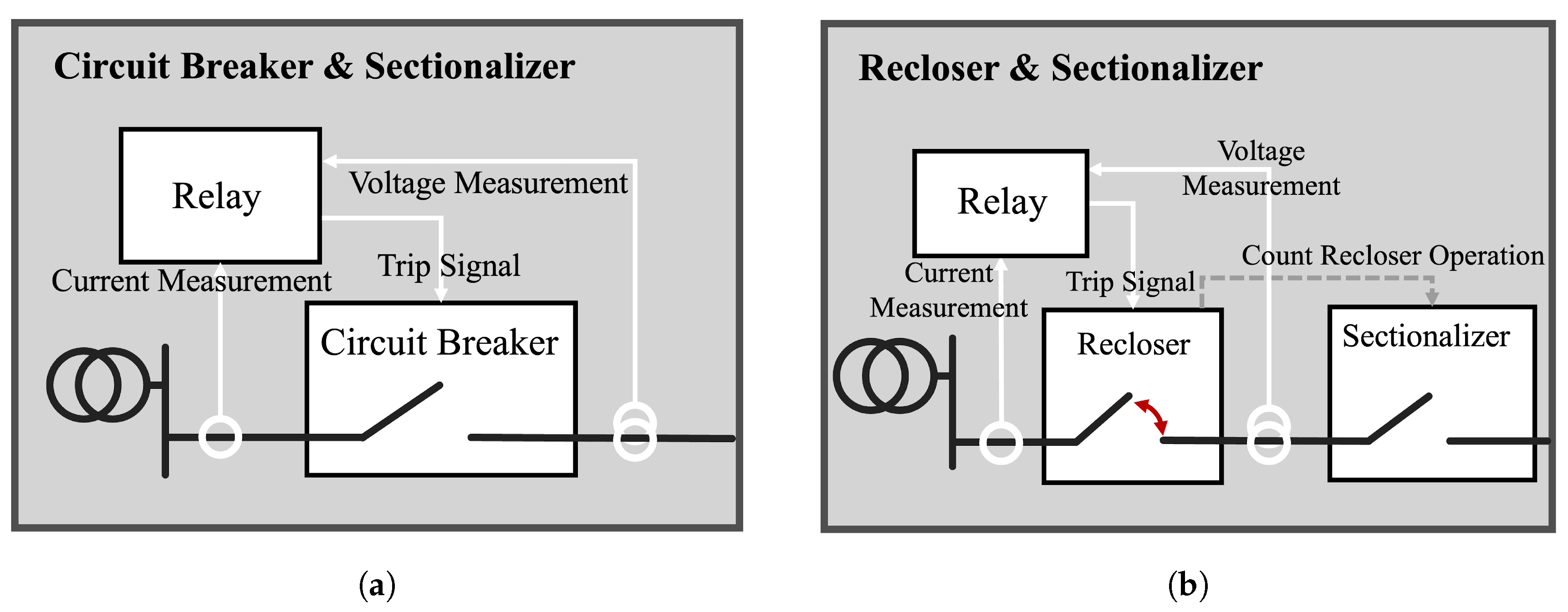
Relay and CB protect the system through the operational linkage shown in the grey box on the left of the protection system in Figure 4a. The relay detects abnormal conditions by measuring current and voltage and sends a trip signal to the CB, which detects the signal from the relay and directly disconnects the grid [33,34]. The protection method that combines relays and CBs has the advantage of reconnecting the grid after the fault situation is resolved, as it uses a switching mechanism rather than a physical characteristic like a fuse.
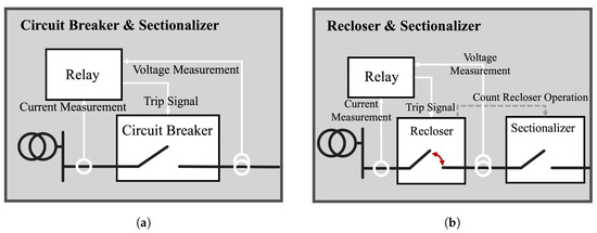
Figure 4.
Coordination and operation of electrical protective devices; (a) relay and circuit breaker operation; (b) recloser and sectionalizer operation.
The operational linkage of the recloser and sectionalizer is shown in Figure 4b. A recloser differs from a one-time grid isolator, such as a CB, in that it repeats a certain number of opening and closing operations. Reclosers are characterized by initially disconnecting the grid upon detecting a fault current and then reconnecting the grid after some time. This feature is designed to assume a temporary fault. Once the fault is resolved during the opening and closing operation, the recloser reconnects the grid without further opening and closing to restore the original operating state. On the other hand, if a fault is detected even after multiple opening and closing operations, the recloser will open the grid permanently to isolate the faulted section from the system and prevent the fault from spreading. The sectionalizer counts the number of open and close operations of the recloser and opens the line if it detects more than a set number of operations. Sectionalizers do not directly block faults, but their simple operation and low cost make them effective in conjunction with reclosers to minimize fault propagation [35].
Although protection device behavior information does not provide direct information about the fault, it is indirectly used to infer the fault location. To illustrate, consider a fault occurring at points 1, 2, and 3, as shown in Figure 5. In the event of a fault at point 1, a line break is typically accompanied by an overcurrent from the substation to the fault point. The system, designed to minimize grid damage through the cooperative protection of multiple devices, allows for the inference that a fault at point 1 has occurred when the CB disconnects the grid. Consequently, a fault at point 2 triggers the operation of the recloser, while a fault at point 3 triggers the operation of the sectionalizer. In this way, since the protector operates by detecting the failure of the measuring point, it is possible to identify the failure of the measuring point through the behavior information of the protector.

Figure 5.
Protective devices’ operation by fault location.
3.2.2. Fault Indicator
Fault indicators (FIs) are essential tools in power distribution systems and are designed to effectively and economically detect disruptions such as short circuits and ground faults [36,37,38]. These devices function by monitoring sudden increases in current flow that result from such faults, which alter the indicators’ internal magnetic fields. This change in magnetic flux is promptly detected by the FIs, triggering an alert mechanism that may display a mechanical flag or send an electronic signal to system operators. This rapid detection enables FIs to identify and accurately locate faults quickly, minimizing system downtime and enhancing overall reliability. While FIs are beneficial for their rapid detection capabilities and ease of integration, they provide only primary fault occurrence data and lack detailed diagnostics.
Given these limitations, alternative methods using FIs have been developed to improve fault location accuracy. One such method is illustrated in Figure 6, which demonstrates how FIs at multiple points within a network can infer the direction and location of a fault more precisely. Figure 6 depicts an FI at points A and B configured to detect downstream fault currents. In the event of a fault between points B and C, the FI at A and B will infer that the fault is in the downstream direction of point B. Conversely, if the fault occurs between points A and B, then the FI at B will not operate, indicating that the fault is in the upstream direction of point B.

Figure 6.
Operational mechanics of fault indicators in detecting faults.
More recently, bidirectional FIs have been used instead of traditional unidirectional FIs due to distributed power sources. This is illustrated by the grey circular dotted line in the figure. A fault between B and C will also generate a fault current from the power source to the fault point in a few situations. If the FI at point C cannot detect the downstream fault current, then the candidate fault location will be inferred to be between B and C or between C and the power source. However, if the FI at point C can detect the bidirectional fault current, then the fault location can be confirmed to be between B and C.
4. Current State of Power System Alarm Processing
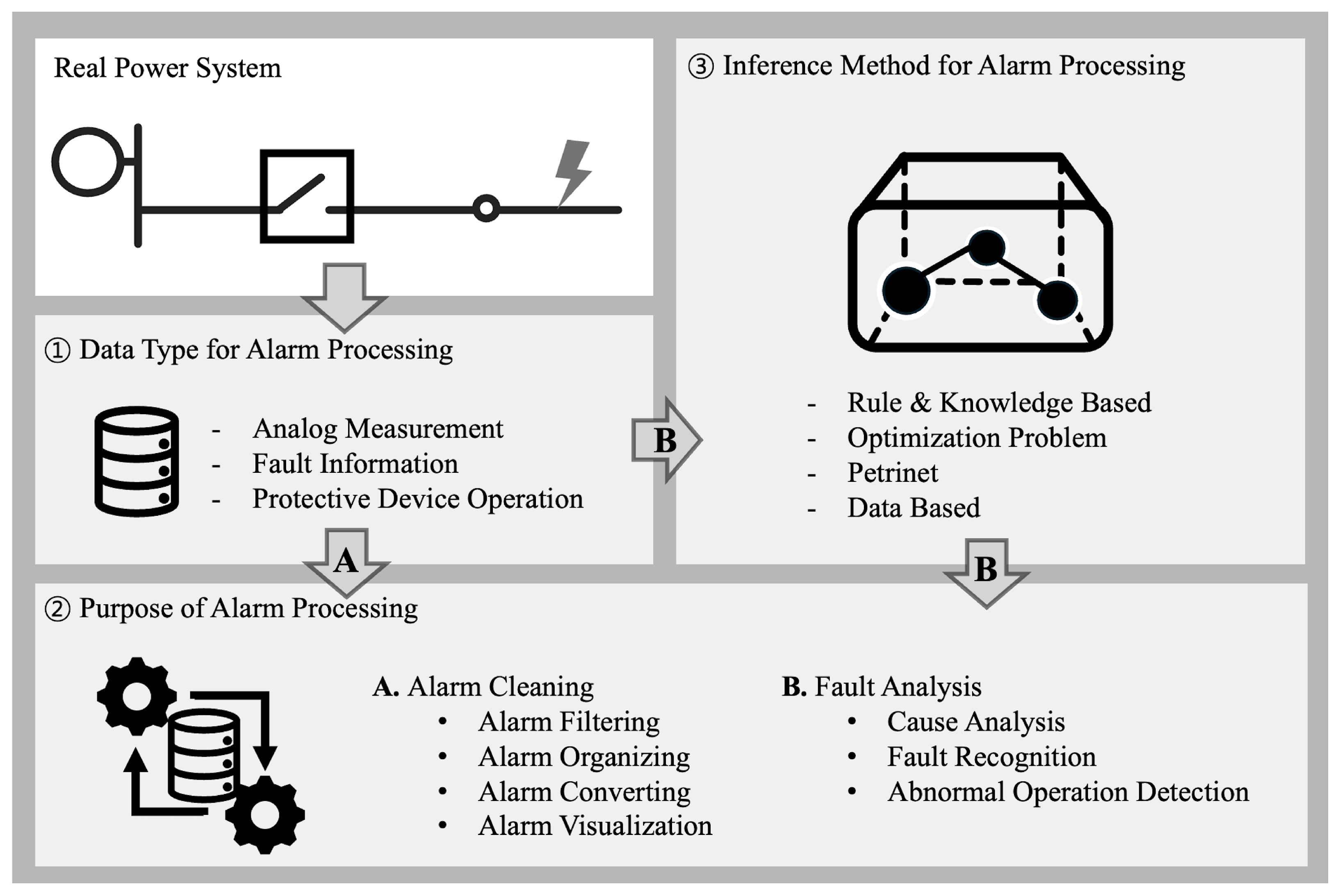
This chapter reviews the power system alarm processing studies published to date according to three main classification criteria, as shown in Figure 7. The first classification is the type of input data used in alarm processing. This classification includes magnitudes of analog measurements, such as voltage and current; fault events that directly indicate the presence of a fault, such as fault indicators; and operational events in which a protective device, such as a relay or breaker, has been tripped. The second classification pertains to the purpose of alarm processing and is intended to identify the kind of information provided to the operator. The third classification is alarm processing modeling, which discusses the methodology used to process alarms.
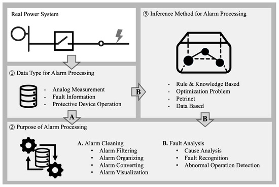
Figure 7.
Classification criteria for alarm processing studies.
4.1. Data Type for Alarm Processing
4.1.1. Analog Measurement
Analog measurements in a system include electrical information such as voltage, current, frequency, etc. These measurements can be utilized in various applications. For instance, voltage measurements at various points within a managed system can be used to assess the system’s overall state [39]. Additionally, three-phase voltage and current information can be employed to analyze system faults [40]. Furthermore, operational data from generators installed in the system can be used to model frequencies and transient frequency data for fault detection [41,42].
4.1.2. Fault Information
Fault information refers to any alarm event that directly indicates a fault. As described in Section 3.2.2, FI is effectively utilized for fault location estimation in distribution systems with radial topology because it detects fault currents in a set direction. However, recently, research has been conducted on fault location estimation using FI, which can detect bidirectional fault currents due to the distributed power sources installed in the distribution system [43,44]. In addition to FI, some studies have employed general fault information, which directly indicates the location of the fault on a specific line and substation, as exemplified by [45].
4.1.3. Protective Device Operation Information
In power systems, relays or circuit breakers are triggered by events such as short circuits and line breaks to protect electrical devices or minimize the impact of incidents. Multiple protective devices may act simultaneously in response to a single incident, and consideration of malfunctions or non-operation of these devices might leave operators with insufficient information for accurate situation assessment based solely on the operational alarms of protective devices. However, activating these protective devices provides direct clues that can be inferred about the incident, which is why most scholarly papers model the protective device operation scheme to construct all possible alarm scenarios for predictable incidents in advance. This approach primarily uses the operational information of protective devices for alarm processing [46,47]. System topology and protective coordination are commonly considered in modeling protective device operation schemes [48,49]. In this context, utilizing the time logs of the protective device operation data allows for verifying the sequence in which the devices were activated [50,51]. An alarm that occurs too late can thus be identified as unrelated to the incident.
4.2. Purpose of Alarm Processing
Alarm processing can be broadly categorized into two types. The first type, represented by arrow A in Figure 7, involves processing collected alarm data to extract, organize, and transform them into information necessary for system operators, a method known as alarm clearing. The second type, represented by arrow B, involves creating an inference model to gain insights into fault situations and perform cause analysis.
4.2.1. Alarm Cleaning
The primary objective of filtering is to reduce the volume of the large amounts of raw alarm data collected. The most straightforward filtering method is to provide the operator with the alarm information after removing specific alarms with a particular frequency [52]. In contrast to this static filtering approach, alarm filtering can also be performed based on simple predetermined rules [52]. For instance, if information indicates that a specific feeder is out of service, then all alarms can be removed [53]. Alternatively, a hierarchical alarm structure can be created in which less-critical child alarms are suppressed if a parent alarm is triggered [54]. In addition, scenario-based filtering using the inference model was also performed. It involved configuring a set of alarms likely to occur for all possible incidents in a given system in advance. Subsequently, alarms not existing in the alarm set were removed by comparing them with real-time alarms [55].
Alarm organization is a method of categorizing a large amount of collected data according to its purpose [56], which is the equivalent of structuring a large amount of raw alarm data from the grid by applying a method to classify it within the system according to the type of data collected. Another organizing method is to classify raw alarm data into sub-events [57]. For example, when system faults occur in succession, the SCADA stores all alarms caused by multiple faults without distinction. Even when the entire alarm data set is divided into time units by introducing a time window, multiple fault information can be included. Therefore, the alarm data are grouped based on specific device operation alarms, such as relay operation, to distinguish alarms corresponding to specific faults.
Alarm converting refers to the preprocessing steps that transform system-generated data into a format suitable for operator use. Typically, this involves handling alarm information presented in text form. Refs. [58,59] introduced a rule-based method for converting alarm messages in various formats into a standard format that can be utilized for processing. The text format collected from the system was converted into time, motion, device, measurement value, and other data types and utilized in specific algorithms. Ref. [45] utilized machine learning to convert critical variables required for alarm procedures from text information into vectors. The converted vectors were later used as input for machine learning and directly used for fault analysis.
The alarm visualization function is a tool that effectively displays alarm information along with the current acquired values. For instance, by displaying not only the measured voltage at a specific point during regular operation but also the average value of the voltage in the surrounding area and then highlighting the alarm information that is out of the limit value during an emergency, it is possible to provide the system status from a macro perspective as well as the grid status at a local location, thus assisting the system operator in making judgments [39]. Furthermore, methods for analyzing the system’s alarms and their causes and for monitoring the causal relationship in real-time have been presented [60,61], and methods for displaying power flow and voltage on a geographical map to assist system operators have been discussed [62,63].
4.2.2. Fault Analysis
Fault analysis is the process of determining the cause of a fault after fault recognition. The system supports system operation by providing this information to the operator. The primary objective of fault recognition is to provide a relatively simple form of fault information. The system information is used to determine whether a fault has occurred or not or to determine the type of fault [42,64,65]. Cause analysis, on the other hand, focuses on analyzing the specific cause of the failure. The general method of analyzing the cause of a fault is to group alarms that may occur in a specific fault in advance and to infer the cause by comparing the alarms that occurred with those that were pre-grouped [50,66]. As previously stated in Section 3.2, since the protection device operation information and FI alarms appear in response to a specific fault location, they can be used to determine the fault location by inferring the alarms that occurred in reverse. For this reason, most alarms employed for fault location determination comprise device behavior information and FI alarms [48,67,68].
Conversely, the operational status of the protective device employed as the foundation for fault analysis is of paramount importance. It is of the utmost significance to ascertain the malfunction of the protective device, as the malfunction can significantly compromise the quality of fault analysis. A malfunction of the protective device denotes that it has operated when it should not. In contrast, a failure of the protective device signifies that it has not operated when it should have. When a protective device fails, a backup protective device is triggered, and it is possible to identify the failed protective device from the protection cooperation information of the system. This is a result of the fault analysis process, and the grouped alarm information for the specific fault mentioned earlier can be used to determine which alarms have been silenced [43,67,69].
4.3. Inference Model for Alarm Processing
4.3.1. Knowledge-Based Modeling
Rule-based modeling configures alarm scenarios for grid faults as if…then conditions. For example, suppose a specific protective device behavior occurs. In that case, several conditional statements can be configured to diagnose the fault location or cause by stating that a fault has occurred at a certain point. This method has the advantage of being relatively straightforward to model, as it defines the relationship between alarms. Furthermore, it is relatively straightforward to modify when new rules arise or when rules need to be removed, which is an advantage in terms of maintainability [50,70]. Logic-based methods employ operations such as AND, OR, or other operations defined by the system designer to organize the relationship between multiple pieces of information in order to identify the cause or location of the fault [66,71,72]. The network method involves approaches that organize relationships between alarms based on the system developer’s predefined criteria. This method calculates the relationships among occurring alarms, particularly by using protective coordination [73,74,75], which essentially relies on topological knowledge of the system. Additionally, this approach includes considering the alarms’ temporal characteristics in order to enhance the relationship’s definition [51,76,77,78].
4.3.2. Optimization Method
Optimization is the method of finding the optimal solution to a problem with constraints. It solves the problem by finding the value that minimizes or maximizes the objective function without violating the constraints. Optimization for alarm processing typically uses an objective function with the form of Equation (2).
In the first term, represents the expected set of alarms due to failure cause x, while A denotes the alarms that occurred. The objective function is the difference between the alarms expected to occur in a particular failure and those that occur. Deriving a solution that minimizes this objective function means identifying a cause that produces alarms similar to the expected alarms. The second term, , is introduced to assess the solution’s reliability regarding the number of causes of failure and false alarms. Minimizing signifies the avoidance of deriving an indiscriminate failure cause x or over-assuming the malfunction situation of the system protection device. In other words, the first term can be minimized if the number of failure causes and protection device malfunctions is over-assumed. However, the reliability of the failure cause is reduced, so a term is added to prevent this. Modeling the is essential for deriving failure causes using optimization methods. Various methods have been developed to identify the expected alarms by modeling the expected alarm set for the behavior of the protector [43,49,79,80,81] or by setting the expected state of the FI signal according to the fault location [44].
Without constraints, optimization methods based on unconstrained objective functions, such as Equation (2), are predominantly employed in meta-heuristic-based approaches. Given that the failure cause has been defined as a binary solution, optimization methods may utilize genetic algorithms [46,79,82], brainstorm optimization [80], or tabu search [81] to identify a solution.
Conversely, in the case of a constrained optimization method that leaves only in the objective function of expression x and reflects the expected alarm, such as , as a constraint, the typical method used when setting the alarm behavior according to the behavior of the protective device is expressed as the two inequalities of Equations (3) and (4) [44,48,57,67,83].
In this context, s represents a false alarm, e denotes a specific event, a signifies a specific alarm, f represents a non-functional alarm, and Equation (3) symbolizes a constraint stipulating that if a specific alarm occurs, a specific event or false alarm must occur. When a particular alarm occurs, and a becomes 1, the inequality expresses that a particular event must occur or a false alarm must exist. Equation (4) illustrates the relationship between a failure event, a specific alarm, and a false alarm. This relationship holds regardless of whether the specific alarm in question occurs. A similar approach is taken in the example above, where e is set to 1 in order to express that if a particular event occurs, some alarm must occur, or at least one of the alarm behaviors must be equal to 1. The above formula establishes the relationship between alarms and failure causes, reflecting a specific system environment. It defines the value of the objective function in Equation (2) as the number of e, s, and f.
Thus far, the methods can be considered models that only consider a preset sequence of actions when a specific alarm occurs. However, this has limitations in multi-fault situations. When the same alarm occurs coincidentally for different failure scenarios, it becomes impossible to determine the exact failure scenario. To address this, alarm occurrence time can be introduced as an additional approach [84]. When considering the expected alarm set, it is possible to reflect temporal characteristics by adding a constraint expression that considers the alarm as not occurring if the expected occurrence time is exceeded [85] or by introducing a penalty term in the objective function to increase the penalty value if the alarm occurs beyond the expected alarm occurrence time [84].
Conversely, the optimization application utilizing FI information is represented by the following Equation (5):
The expected alarm of the specific FI is represented by the symbol F. The increasing introduction of distributed power sources in the distribution system has led to the requirement for bidirectional FIs, which differ from the traditional unidirectional downstream FIs. In a bidirectional FI, the bidirectional alarm is set to three values: 0, 1, and −1. These values represent no FI operation, fault current generation in the downstream direction, and fault generation in the upstream direction, respectively. indicates the degree to which a specific FI causes a fault in a specific direction, while indicates the degree to which it causes a fault in the opposite direction. Consequently, the calculation of and using system alarm information represents a pivotal approach to modeling the anticipated direction of FI [43,86]. In the event of a specific FI, a power source in the upstream direction and a fault will result in a heightened probability of the FI occurring in the downstream direction. In contrast, the presence of a power source in the downstream direction and the occurrence of a fault will result in a heightened probability of the FI occurring in the upstream direction.
4.3.3. Petrinet
Petrinet is an appropriate tool for modeling relationships between components that comprise asynchronous and concurrent systems. It has been employed to model power protection systems with multiple interacting components, such as protection relays and protection coordination [87,88,89]. Petrinet is comprised of two fundamental elements: places and transitions. Places represent the state of the system, while transitions represent events that result in changes to the system. The relationship between places and transitions is defined by an arc, which illustrates the transition of tokens (representing resources or activities) from places to transitions.
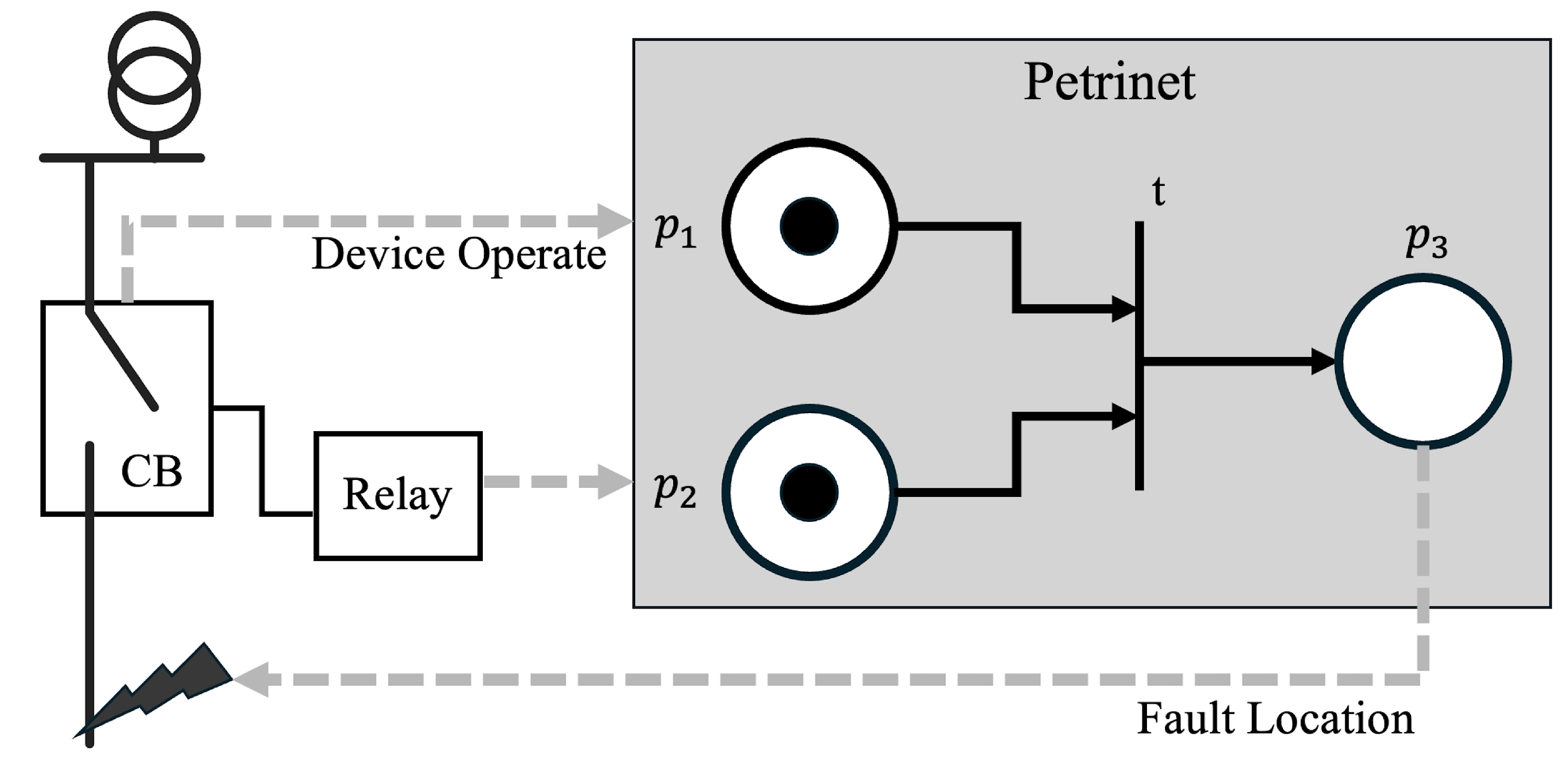
Figure 8 depicts a partial representation of a petrinet, which describes the simplest example of a petrinet that represents the failure of a particular line based on the behavior of a protective device. As a fundamental example, consider the case where a fault triggers a relay, which in turn triggers a CB. If a token exists at , which is a place corresponding to a specific relay, and a failure at a specific location causes a token to be created at , then at transition t, a token is created at because tokens exist at both input places. If this is set as a CB triggered by the relay, then the sequence of protector actions due to a fault can be modeled.
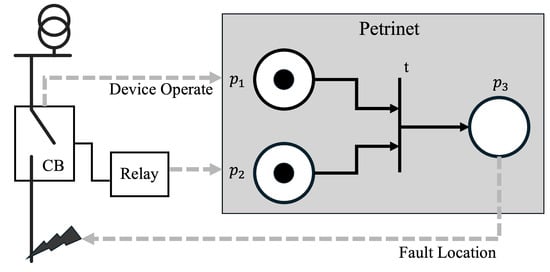
Figure 8.
Petrinet and its application in fault analysis.
One possible application of this petrinet to a fault location method is assigning a fault cause corresponding to the last place in this petrinet. In a situation analogous to the one above, the behavior of a particular relay is set to generate a token in , as illustrated in the accompanying figure. Then, a token in is generated when the CB behavior is confirmed. Since both and have a token at the input place, the transition condition is satisfied, and a token is created in . By setting this as the fault of a specific location, a petrinet model can be created to diagnose which fault has occurred based on the alarms that occur [90].
The preceding example illustrates the use of deterministic modeling, which may be suitable for representing ideal protector behavior. However, it is not a valid model for abnormal alarms resulting from misoperation. To address the uncertainty associated with power system alarms, a fuzzy petrinet is employed, wherein tokens are assigned values, and transitions are used to derive the probability of failure [89,91,92]. In other words, by incorporating a fuzzy logic approach, the greater the number of alarms that align with the specified scenario, the higher the token value corresponding to the underlying cause of the failure. This allows for the determination of the cause of the failure.
4.3.4. Data-Based Modeling
Data-driven models are employed to train a model that can fulfill a specific function through data or to identify problematic situations in a system through data analysis techniques. Trained models are primarily utilized to represent systems with pronounced nonlinearity [93,94,95]. Given that the model’s internal parameters can reflect nonlinear states, it is possible to create complex models with high flexibility. One common application of this approach to alarm processing is to train a model from a set of inputs and outputs that take as input the alarm pattern that occurs and output the cause or location of the fault [96]. Additionally, Ref. [41] employs the active utilization of analog information from the power system to create a model that can mimic the system dynamics and be used for fault analysis. Conversely, a data analysis technique that only utilizes models employs principal component analysis (PCA) to derive the information necessary for fault recognition [42].
Table 1 summarizes the categorization of all the papers referenced in the analysis, including the representative papers described thus far. Additionally, Table 2 comprehensively compares various alarm processing methods used in power systems. This comparison includes each method’s principles of operation, advantages, and limitations, offering a detailed overview of how these methods can be applied to enhance alarm management in complex power systems.

Table 1.
Comprehensive classification of alarm processing features.

Table 2.
Comparison of alarm processing methods in power systems.
5. Discussion
This chapter examines the limitations of traditional alarm processing and considers future developments. To this end, the first and second generations of alarm processing are defined as past and present methods, respectively. Their characteristics and the reasons for their transitions are described, along with an examination of the future power system environment and the limitations of second-generation alarm processing. Finally, the potential developments in third-generation alarm processing are outlined.
5.1. First-Generation Alarm Processing
The operating environment of earlier power systems was less complex than today, and raw data generated by system events were used to provide organized and timely information [32]. First-generation alarm processing simply aimed to process information without needing complex calculations, and the results could be presented directly to the operator. Most of the methods classified as alarm cleaning in Section 4 fall into this type of alarm processing, which supports operator judgment by filtering, organizing, and transforming.
5.2. Transition to Second-Generation Alarm Processing
This first-generation approach has reached a tipping point with the modernization of power systems. The main changes brought about by modernization include an increase in the size and complexity of the system and a higher volume of information processing. As demand increased, more lines, generators, and power equipment were installed [124], and the introduction of advanced metering, cloud computing, and other computing technologies began to generate vast amounts of data [125]. First-generation alarm processing began to show its limitations in assisting operators under such conditions, and the need for what is known as intelligent alarm processing (IAP) began to emerge [32]. In particular, the large amounts of data typically generated during system failures expanded the scope of alarm processing to include aspects of what is known as fault diagnosis.
As shown in Table 3, alarm processing and fault diagnosis have traditionally been distinguished as processes with different characteristics [126]. Alarm processing is undertaken to present a global situation using SCADA data, while fault diagnosis focuses on identifying the causes of faults using related information. However, the modernization of power systems has blurred the distinctions between the purposes and characteristics of these two processes. Ultimately, second-generation alarm processing has taken over the role of fault analysis by inferring the causes of faults. As evidence, the literature does not distinguish between the definitions of alarm processing and fault diagnosis, as confirmed in Table 4.

Table 3.
Different characteristics of alarm processing and fault diagnosis.

Table 4.
Descriptions of alarm processing and fault diagnosis in various papers.
In [103], alarm processing has been described as part of fault diagnosis in fault situations, identifying the location and cause of faults, and Ref. [127] has described fault diagnosis as one of the primary objectives of alarm processing, showing an apparent lack of distinction between the two functions. Ref. [72] has defined the functions of both processes as fault detection and protection device operation. In particular, Ref. [72] described alarm processing as a preprocessing step in fault diagnosis, positioning it as a dependent process. In contrast, Ref. [97] described it conversely as a process that presents results to the operator through the alarm processing system after fault diagnosis.
5.3. Second-Generation Alarm Processing
Second-generation alarm processing differs from first-generation in two points. The first point is that second-generation processing can internally infer information previously left to the operator in first-generation processing. Second-generation alarm processing has become more advanced by inferring new information about the cause of a fault from the data rather than simply processing it. The other is that second-generation alarm processing uses modeling of the power system situation to infer the causes of faults. This complex process of inferring fault causes models scenarios of power system behavior specific to particular faults, and fault analysis is performed through comparison with actual system alarms.
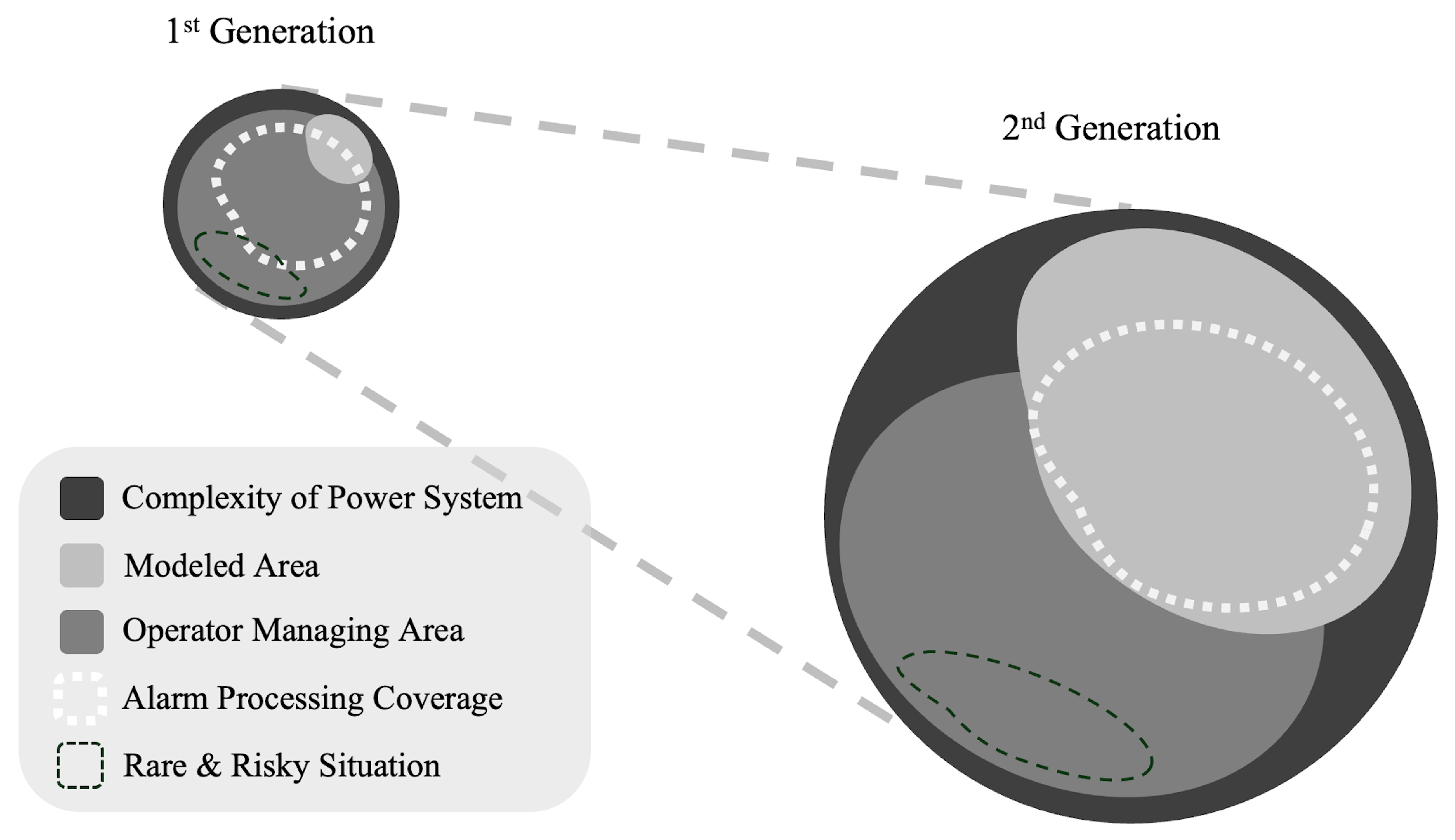
In summary, Figure 9 illustrates the roles of first-generation and second-generation alarm processing. First-generation alarm processing operated when system complexity was relatively low and the system was managed primarily based on operator judgment. In such an environment, although alarm processing did not require complex reasoning, it played an overall role in assisting the operator. However, with the transition to the second generation, alarm processing began to be used for fault diagnosis, making effective use of the areas that could be modeled within the power system domain.
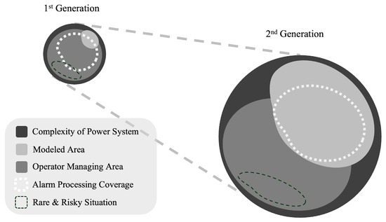
Figure 9.
Generational transition in alarm processing and expanding areas of focus.
5.4. Third-Generation Alarm Processing
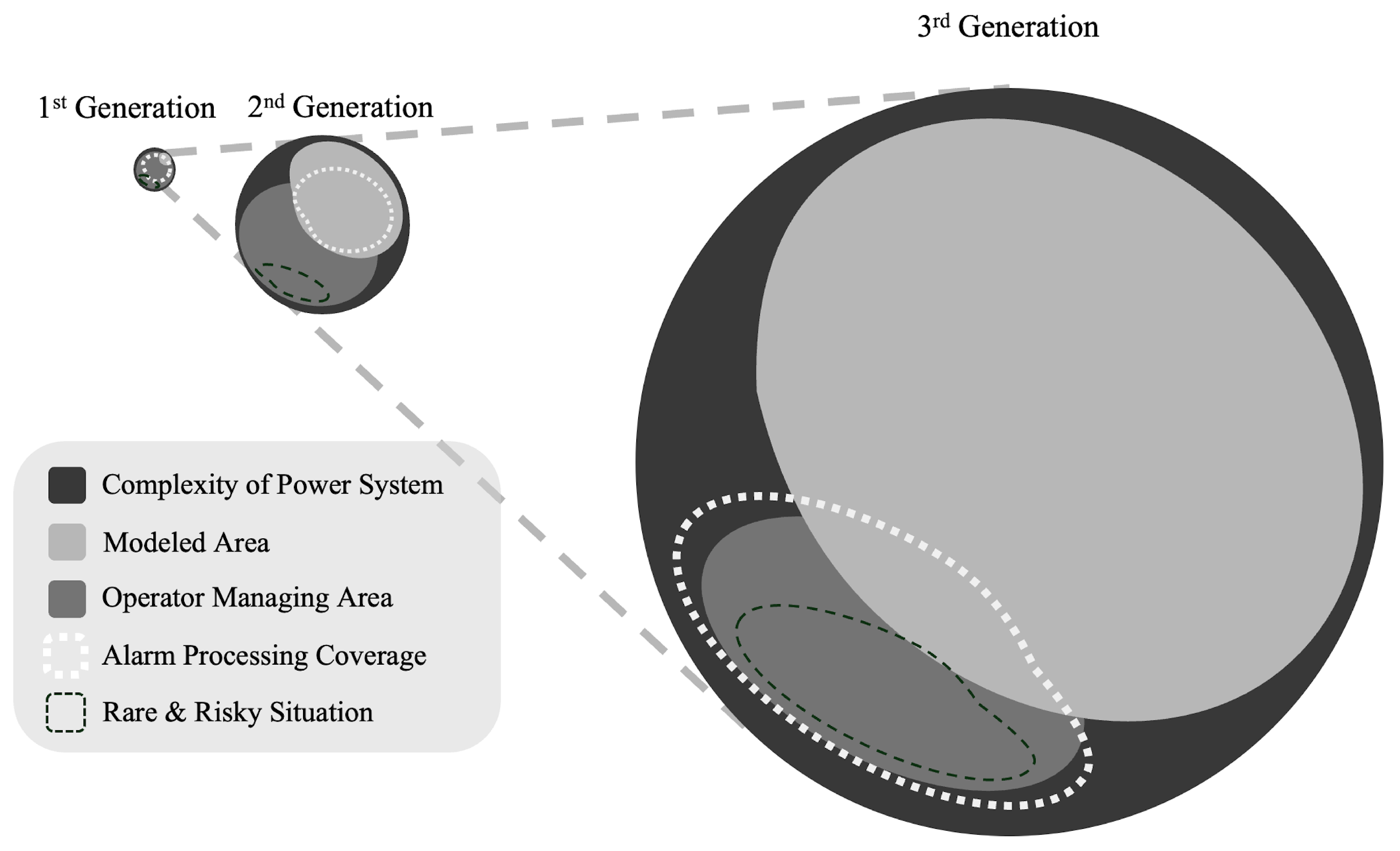
In the future operating environment of power systems, where third-generation alarm processing will be used, the modeling domain mentioned in the second generation one will be further extended. Future power systems are expected to solve various problems through automated systems [128,129], and achieving such automation requires exact, detailed system modeling. For example, models that address various power system problems will be implemented, ranging from fault cause inference models based on the operational characteristics of specific faults, similar to second-generation alarm processing, to models that control system operations such as switch management and fault recovery. As multi-system models take over the management of many system problems, the scenarios requiring operator judgment are inevitably reduced. For example, if faults can be located and recovered automatically, there will be no need for operator intervention in these processes.
However, while the situations requiring judgment are reduced, operator intervention in unmodeled situations, i.e., rare and poorly understood conditions, remains essential [130]. The impact of power supply problems due to natural conditions in renewable energy sources or operational failures due to automated model errors represents a fundamental risk that automated systems cannot resolve. Therefore, the operator’s role still remains critical in future power systems [131,132,133]. While effective in providing information from modeled situations, second-generation alarm processing is limited in providing valuable information for rare events. Therefore, the next goal of third-generation alarm processing should be to focus on assisting operators with rare events.
Figure 10 illustrates the tasks that third-generation alarm processing should address in the system environment. In the future, the system situation will increase significantly in terms of the number of conditions that can be modeled. In such cases, alarm processing should provide information about the modeled areas and meaningful information to the system operator about situations that have not yet been modeled. Therefore, while focusing on assisting the operator like in the first generation, alarm processing should cover areas related to more infrequent events. Here, focusing on unsupervised machine learning methods such as anomaly detection is crucial.
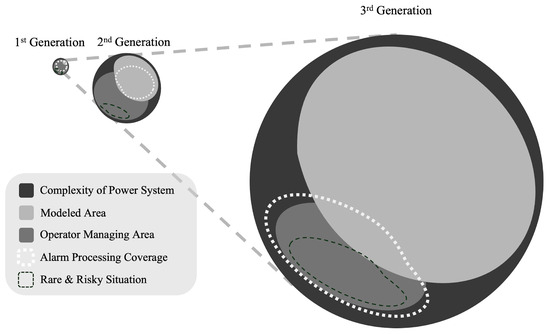
Figure 10.
Third-generation alarm processing and areas of focus.
5.4.1. Unsupervised Learning: Anomaly Detection
Although machine learning has been used in various cases in traditional alarm processing, this approach has its limitations due to the impossibility of modeling rare events [134,135,136]. The rare events that third-generation alarm processing seeks to address are inherently lacking in data, making it impossible to train a data-based model that reflects them.
When there are limitations in collecting data from fault conditions, an alternative is to use data from normal conditions. Anomaly detection in machine learning involves training a model on normal data and then detecting deviations when data that deviate from the typical situation are encountered. Training the model on data from the normal state of the power system and establishing a baseline for the normal state makes it possible to detect deviations when abnormal patterns occur in system failure situations. By continuously monitoring system performance in this way, the model can alert operators to anomalies before actual system failures occur, providing early warning of potential problems. Ultimately, the move away from supervised models that learn correct answers in traditional methods to unsupervised learning models capable of detecting abnormal situations is essential for future alarm processing methods.
When applying anomaly detection, two additional aspects need to be considered. First, the scalability of the model must be adequately addressed. Machine learning methods used in second-generation alarm processing typically set the output dimension to the number of fault causes and train the model based on system data corresponding to each fault cause. If new fault causes need to be included, new data corresponding to these faults must be acquired, and the model must be retrained. This leads to system application limitations when environmental conditions change, and the required output dimensions shift [137]. As the system frequently changes topology and integrates many distributed power sources, the output dimensions of the model must be capable of continuous adaptation. Therefore, models that can take full advantage of scalability, as used in other fields, should be used [138,139,140,141].
Second, machine learning models must be interpretable in order to justify judgments about anomalous situations. While the various parameters and structures of machine learning models are designed to solve non-linear problems effectively, the complexity of these structures can make the decision-making process more transparent. Typically, model effectiveness is verified by checking the appropriateness of the model outputs in test situations. However, this method has limitations, as it fails to ensure the reliability of the results [142,143]. An alarm processing result that cannot be trusted makes it difficult to justify its validity.
Therefore, the development of machine learning models for third-generation alarm processing should consider applying explainable AI (XAI) technologies to enable model interpretation. This allows operators to understand and trust the AI’s decision-making process, supporting more effective decision-making. Alarm processing systems developed with XAI technologies can present the reasoning behind each alarm, enabling operators to diagnose and respond to problems more accurately and quickly. Particularly in the complex fault situations that can occur in power systems, this will help assess the importance and priority of alarms, increase the efficiency of alarm processing, and improve the overall stability and reliability of the system.
5.4.2. Conceptual Framework of Third-Generation Alarm Processing
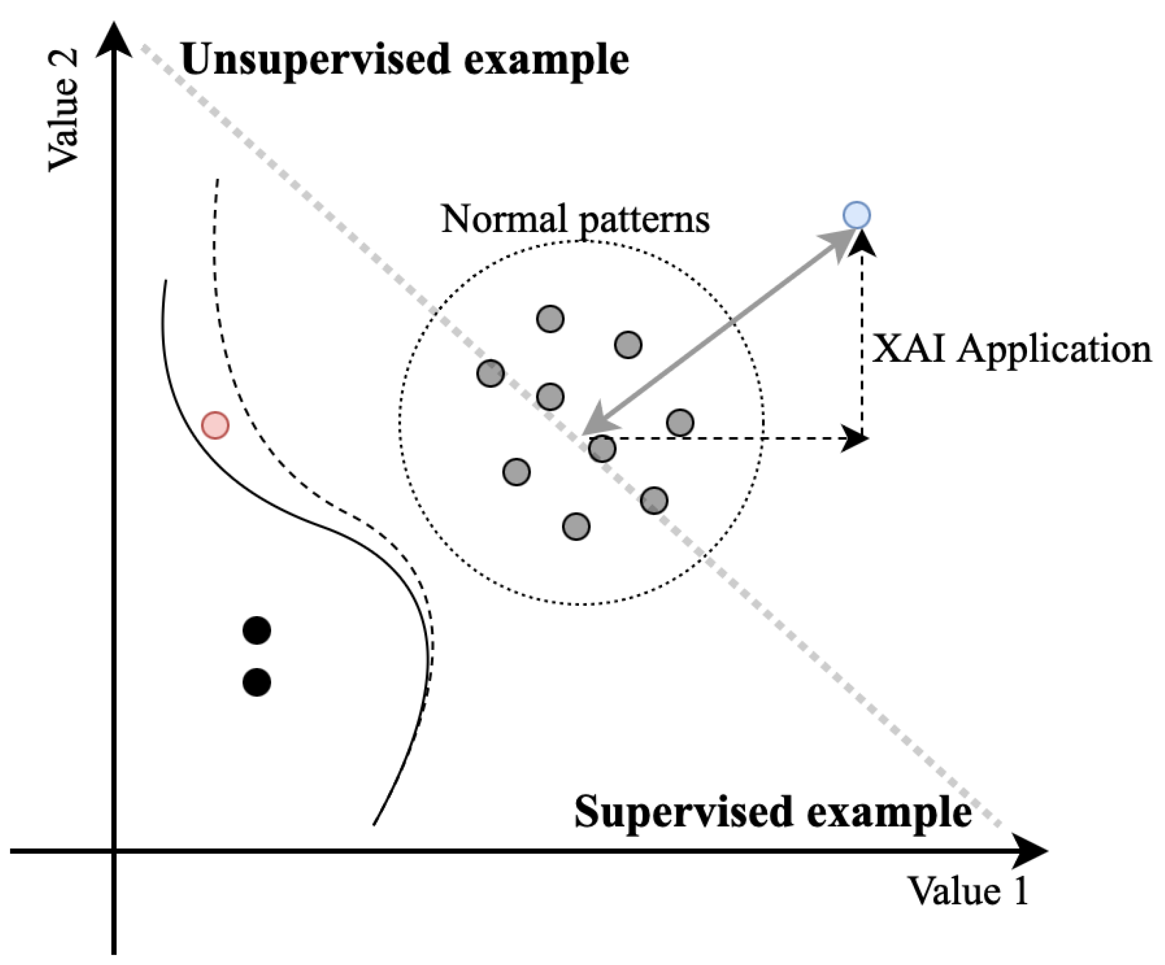
Figure 11 illustrates an example of the third-generation alarm processing method presented in this paper. It simplifies various measured values in the system into “value 1” and “value 2”, illustrating each corresponding data point in a scatter plot. Typically, the data collected within the system indicate normal conditions and thus comprise the majority of the data set. The data sets plotted in the bottom-left are associated with faults, where each value could potentially be labeled according to the fault location or cause. Conventional supervised modeling of this data set would form a solid black line to distinguish these conditions, and newly entered data depicted in red would be classified under the normal pattern.
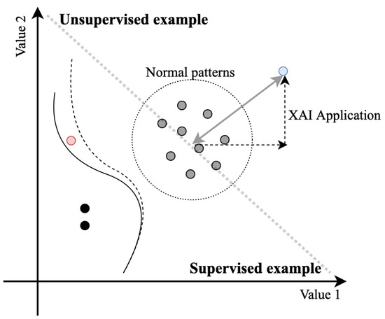
Figure 11.
Schematic representation of a third-generation alarm processing method.
However, this method is contingent upon the availability of sufficient fault data to ensure reliability. Without enough data, the data points marked in red may represent faults, which could give rise to significant operational issues. To address this, analyzing such data and their subsequent relabeling to indicate the specific faults allows for training a new model, which would then learn a new dotted boundary line. While this model-learning approach is suitable for the post-processing style of second-generation alarm processing, it carries the risk of misjudgment each time unlearned data occur.
In contrast, third-generation alarm processing exclusively compares newly occurring rare events with data representing normal conditions. To illustrate, consider a scenario in which data depicted in blue emerges. If the data deviate from the normal pattern, they would be recognized as such, and the degree of deviation would be provided to the operator. This redefines the challenge from merely deciding whether the data indicate a fault or normalcy to recognizing deviations from normalcy, thereby reducing the risk associated with judging unknown system states. By employing XAI technologies, this method of alarm processing not only identifies the input pattern as anomalous but also provides operators with insights into the why of this deviation from the normal state pattern and the extent to which specific values contribute to these discrepancies. This offers operators quantitative insights that assist them in making informed decisions.
6. Conclusions
This paper has reviewed alarm processing methods for handling fault alarms in electrical power systems. By analyzing existing research papers on alarm processing, the authors have evaluated the current state of research based on the types of data used, the objectives of alarm processing, and the methodologies employed. The authors also discussed the characteristics of past and modern alarm processing methods by defining three generations of alarm processing based on their objectives. Based on this discussion, the direction of third-generation alarm processing methods suitable for future power system environments has been addressed. While previous approaches have dealt with alarms based on understanding complex system situations, new alarm processing emphasizes providing operators with actionable information for rare events. The authors proposed using anomaly detection based on unsupervised learning to handle rare events. They emphasized the need to use scalable models and apply XAI methods to ensure both the scalability and reliability of the models.
Author Contributions
Conceptualization, J.-Y.O. and J.-M.S.; methodology, J.-Y.O. and J.-M.S.; formal analysis, J.-Y.O. and J.-M.S.; investigation, J.-Y.O. and J.-M.S.; writing—original draft preparation, J.-Y.O. and J.-M.S.; writing—review and editing, Y.T.Y.; visualization, J.-Y.O.; supervision, J.-M.S. All authors have read and agreed to the published version of the manuscript.
Funding
This research was supported by Regional Innovation Strategy (RIS) through the National Research Foundation of Korea (NRF) funded by the Ministry of Education (MOE) (2021RIS-004).
Conflicts of Interest
The authors declare no conflicts of interest.
References
- Kumari, N.; Sharma, A.; Tran, B.; Chilamkurti, N.; Alahakoon, D. A Comprehensive Review of Digital Twin Technology for Grid-Connected Microgrid Systems: State of the Art, Potential and Challenges Faced. Energies 2023, 16, 5525. [Google Scholar] [CrossRef]
- Li, Y.; Green, T.C.; Gu, Y. The intrinsic communication in power systems: A new perspective to understand synchronization stability. IEEE Trans. Circuits Syst. I Regul. Pap. 2023, 70, 4615–4626. [Google Scholar] [CrossRef]
- da Cruz, C.M.; Rocco, A.; Mario, M.C.; Garcia, D.; Lambert-Torres, G.; Abe, J.M.; Torres, C.R.; da Silva Filho, J.I. Application of paraconsistent artificial neural network in statistical process control acting on voltage level monitoring in electrical power systems. In Proceedings of the 2015 18th International Conference on Intelligent System Application to Power Systems (ISAP), Porto, Portugal, 11–16 September 2015; IEEE: Piscataway, NJ, USA, 2015; pp. 1–6. [Google Scholar] [CrossRef]
- Montgomery, D.C. Introduction to Statistical Quality Control; John Wiley & Sons: Hoboken, NJ, USA, 2007. [Google Scholar]
- Bale, C.S.; Varga, L.; Foxon, T.J. Energy and complexity: New ways forward. Appl. Energy 2015, 138, 150–159. [Google Scholar] [CrossRef]
- Ridha, E.; Nolting, L.; Praktiknjo, A. Complexity profiles: A large-scale review of energy system models in terms of complexity. Energy Strategy Rev. 2020, 30, 100515. [Google Scholar] [CrossRef]
- Zhang, Y.; Huang, T.; Bompard, E.F. Big data analytics in smart grids: A review. Energy Inf. 2018, 1, 8. [Google Scholar] [CrossRef]
- ANSI/ISA-18.2; Mangement of Alarm Systems for the Process Industries. International Society of Automation: Research Triangle Park, NC, USA, 2009.
- Stauffer, T.; Clarke, P. Using alarms as a layer of protection. Process Saf. Prog. 2016, 35, 76–83. [Google Scholar] [CrossRef]
- Hollifield, B.R.; Habibi, E. Alarm Management: A Comprehensive Guide; Isa: Research Triangle Park, NC, USA, 2010. [Google Scholar]
- Bergquist, T.; Ahnlund, J.; Larsson, J.E. Alarm reduction in industrial process control. In Proceedings of the EFTA 2003. 2003 IEEE Conference on Emerging Technologies and Factory Automation. Proceedings (Cat. No. 03TH8696), Lisbon, Portugal, 16–19 September 2003; IEEE: Piscataway, NJ, USA, 2003; Volume 2, pp. 58–65. [Google Scholar] [CrossRef]
- Stanton, N.A.; Baber, C. Alarm-initiated activities: An analysis of alarm handlingby operators using text-based alarm systems in supervisory control systems. Ergonomics 1995, 38, 2414–2431. [Google Scholar] [CrossRef]
- IEC. Management of Alarm Systems for the Process Industries; IEC: Geneva, Switzerland, 2014. [Google Scholar]
- Beebe, D.; Ferrer, S.; Logerot, D. The connection of peak alarm rates to plant incidents and what you can do to minimize. Process Saf. Prog. 2013, 32, 72–77. [Google Scholar] [CrossRef]
- Laberge, J.C.; Bullemer, P.; Tolsma, M.; Dal Vernon, C.R. Addressing alarm flood situations in the process industries through alarm summary display design and alarm response strategy. Int. J. Ind. Ergon. 2014, 44, 395–406. [Google Scholar] [CrossRef]
- Srinivasan, R.; Liu, J.; Lim, K.; Tan, K.; Ho, W. Intelligent alarm management in a petroleum refinery. Hydrocarb. Process. 2004, 83, 47–54. [Google Scholar]
- EEMUA. 191-Alarm Systems: A Guide to Design, Management and Procurement, 3rd ed.; EEMUA: London, UK, 2013. [Google Scholar]
- Nochur, A.; Vedam, H.; Koene, J. Alarm performance metrics. IFAC Proc. Vol. 2001, 34, 203–208. [Google Scholar] [CrossRef]
- Bransby, M.; Jenkinson, J. The Management of Alarm Systems; Citeseer, 1998. Available online: https://humanfactors101.com/wp-content/uploads/2016/05/the-management-of-alarm-systems.pdf (accessed on 29 June 2024).
- Azhar, S.B.; Rissanen, M.J. Evaluation of parallel coordinates for interactive alarm filtering. In Proceedings of the 2011 15th International Conference on Information Visualisation, London, UK, 13–15 July 2011; IEEE: Piscataway, NJ, USA, 2011; pp. 102–109. [Google Scholar] [CrossRef]
- Mattiasson, C. The alarm system from the operator’s perspective. In Proceedings of the 1999 International Conference on Human Interfaces in Control Rooms, Cockpits and Command Centres, Bath, UK, 21–23 June 1999; IET: London, UK, 1999; pp. 217–221. [Google Scholar] [CrossRef]
- Noyes, J. Alarm systems: A guide to design, management and procurement. Eng. Manag. J. 1999, 9, 226. [Google Scholar]
- Pariyani, A.; Seider, W.D.; Oktem, U.G.; Soroush, M. Incidents investigation and dynamic analysis of large alarm databases in chemical plants: A fluidized-catalytic-cracking unit case study. Ind. Eng. Chem. Res. 2010, 49, 8062–8079. [Google Scholar] [CrossRef]
- Jain, P.; Pasman, H.J.; Waldram, S.P.; Rogers, W.J.; Mannan, M.S. Did we learn about risk control since Seveso? Yes, we surely did, but is it enough? An historical brief and problem analysis. J. Loss Prev. Process Ind. 2017, 49, 5–17. [Google Scholar] [CrossRef]
- Enescu, F.M.; Bizon, N. SCADA applications for electric power system. In Reactive Power Control in AC Power Systems: Fundamentals and Current Issues; Springer: Cham, Switzerland, 2017; pp. 561–609. [Google Scholar] [CrossRef]
- Kato, D.; Horii, H.; Kawahara, T. Next-generation SCADA/EMS designed for large penetration of renewable energy. Hitachi Rev. 2014, 63, 151–155. [Google Scholar]
- Collier, S.E. Ten steps to a smarter grid. IEEE Ind. Appl. Mag. 2010, 16, 62–68. [Google Scholar] [CrossRef]
- IEEE Std 999-1992; IEEE Recommended Practice for Master/Remote Supervisory Control and Data Acquisition (SCADA) Communications. IEEE: Piscataway, NJ, USA, 1993. [CrossRef]
- Chikuni, E.; Dondo, M. Investigating the security of electrical power systems SCADA. In Proceedings of the AFRICON 2007, Windhoek, South Africa, 26–28 September 2007; IEEE: Piscataway, NJ, USA, 2007; pp. 1–7. [Google Scholar] [CrossRef]
- Dondo, M.C.; El-Hawary, M. An approach to implement electricity metering in real-time using artificial neural networks. IEEE Trans. Power Deliv. 2003, 18, 383–386. [Google Scholar] [CrossRef]
- Fowle, F.F.; Knowlton, A.E. Standard Handbook for Electrical Engineers; McGraw-Hill: New York, NY, USA, 1925; Volume 5. [Google Scholar]
- Bo, Z.-Q.; Lin, X.-N.; Wang, Q.-P.; Yi, Y.-H.; Zhou, F.-Q. Developments of power system protection and control. Prot. Control. Mod. Power Syst. 2016, 1, 7. [Google Scholar] [CrossRef]
- Zubic, S.; Gajic, Z.; Kralj, D. Line protection operate time: How fast shall it be? IEEE Access 2021, 9, 75608–75616. [Google Scholar] [CrossRef]
- Agwa, A.M.; El-Fergany, A.A. Protective Relaying Coordination in Power Systems Comprising Renewable Sources: Challenges and Future Insights. Sustainability 2023, 15, 7279. [Google Scholar] [CrossRef]
- Anderson, P.M.; Henville, C.F.; Rifaat, R.; Johnson, B.; Meliopoulos, S. Power System Protection; John Wiley & Sons: Hoboken, NJ, USA, 2022. [Google Scholar]
- Muench, F.J.; Wright, G.A. Fault indicators: Types, strengths & applications. IEEE Trans. Power Appar. Syst. 1984, 12, 3688–3693. [Google Scholar] [CrossRef]
- Harmand, Y. Fault Management in Electrical Distribution Systems. Final Report of the CIRED Working Group WG03 Fault Management FOREWORD. 1999. Available online: https://www.semanticscholar.org/paper/FAULT-MANAGEMENT-IN-ELECTRICAL-DISTRIBUTION-SYSTEMS-Harmand/db5fd01e897b0424ec77dfb188fa3552f2039b32 (accessed on 29 June 2024).
- Smallwood, C.; Lattner, M.; Gardner, T. Expansion of distribution automation with communicating faulted circuit indicators. In Proceedings of the 2011 Rural Electric Power Conference, Chattanooga, TN, USA, 10–13 April 2011; IEEE: Piscataway, NJ, USA, 2011; pp. B6-1–B6-6. [Google Scholar] [CrossRef]
- Avouris, N. Abstractions for operator support in energy management systems. Int. J. Electr. Power Energy Syst. 2001, 23, 333–341. [Google Scholar] [CrossRef]
- Hor, C.L.; Crossley, P.A.; Watson, S.J. Building knowledge for substation-based decision support using rough sets. IEEE Trans. Power Deliv. 2007, 22, 1372–1379. [Google Scholar] [CrossRef]
- Rigatos, G.; Siano, P.; Piccolo, A. Neural network-based approach for early detection of cascading events in electric power systems. IET Gener. Transm. Distrib. 2009, 3, 650–665. [Google Scholar] [CrossRef]
- Guo, Y.; Li, K.; Laverty, D.; Xue, Y. Synchrophasor-based islanding detection for distributed generation systems using systematic principal component analysis approaches. IEEE Trans. Power Deliv. 2015, 30, 2544–2552. [Google Scholar] [CrossRef]
- Shen, G.; Zhang, Y.; Qiu, H.; Wang, C.; Wen, F.; Salam, M.A.; Weng, L.; Yu, B.; Chen, J. Fault diagnosis with false and/or missing alarms in distribution systems with distributed generators. Energies 2018, 11, 2579. [Google Scholar] [CrossRef]
- Wang, C.; Pang, K.; Xu, Y.; Wen, F.; Palu, I.; Feng, C. A linear integer programming model for fault diagnosis in active distribution systems with bi-directional fault monitoring devices installed. IEEE Access 2020, 8, 106452–106463. [Google Scholar] [CrossRef]
- Zhang, M.; Shen, P.; Zhao, Y.; Liu, Y. Grid monitoring alarm event recognition method integrating expert rules and deep learning. In Proceedings of the 2019 4th International Conference on Mechanical, Control and Computer Engineering (ICMCCE), Hohhot, China, 25–27 October 2019; IEEE: Piscataway, NJ, USA, 2019; pp. 389–3894. [Google Scholar] [CrossRef]
- Wen, F.; Han, Z. Fault section estimation in power systems using a genetic algorithm. Electr. Power Syst. Res. 1995, 34, 165–172. [Google Scholar] [CrossRef]
- Lee, H.J.; Ahn, B.S.; Park, Y.M. A fault diagnosis expert system for distribution substations. IEEE Trans. Power Deliv. 2000, 15, 92–97. [Google Scholar] [CrossRef]
- Fritzen, P.C.; Zauk, J.M.; Cardoso, G., Jr.; de Lima Oliveira, A.; de Araújo, O.C.B. Hybrid system based on constructive heuristic and integer programming for the solution of problems of fault section estimation and alarm processing in power systems. Electr. Power Syst. Res. 2012, 90, 55–66. [Google Scholar] [CrossRef]
- Xu, B.; Yin, X.; Pang, S.; Yin, X. A Novel Analytic Method for Power System Alarm Processing Employing Topological Description. In Proceedings of the 2019 IEEE Power & Energy Society General Meeting (PESGM), Atlanta, GA, USA, 4–8 August 2019; IEEE: Piscataway, NJ, USA, 2019; pp. 1–5. [Google Scholar] [CrossRef]
- Edwards, C.J.; Davidson, E.M.; McArthur, S.D.; Watt, I.; Cumming, T. Flexible model-based alarm processing for protection performance assessment and incident identification. IEEE Trans. Power Syst. 2013, 28, 2584–2591. [Google Scholar] [CrossRef]
- Cui, Y.; Shi, J.; Wang, Z. Power system fault reasoning and diagnosis based on the improved temporal constraint network. IEEE Trans. Power Deliv. 2015, 31, 946–954. [Google Scholar] [CrossRef]
- Siemens AG. Smart Alarm Hiding in SIMATIC PCS 7. 2018. Available online: https://support.industry.siemens.com/cs/ww/en/view/55699984 (accessed on 26 June 2024).
- Shoop, A.H.; Silverman, S. A real-time alarm processor. Int. J. Electr. Power Energy Syst. 1992, 14, 108–113. [Google Scholar] [CrossRef]
- Schneider Electric. Smart Alarming Management. 2013. Available online: https://www.slideshare.net/slideshow/smart-alarming-2012-17230151/17230151 (accessed on 26 June 2024).
- Guo, W.; Wei, L.; Wen, F.; Liao, Z.; Liang, J.; Tseng, C.L. An on-line intelligent alarm analyzer for power systems based on temporal constraint network. In Proceedings of the 2009 International Conference on Sustainable Power Generation and Supply, Nanjing, China, 6–7 April 2009; IEEE: Piscataway, NJ, USA, 2009; pp. 1–7. [Google Scholar] [CrossRef]
- Siddiqi, U.R.; Lubkeman, D. An automated strategy for the processing and analysis of distribution automation data. IEEE Trans. Power Deliv. 1991, 6, 1216–1223. [Google Scholar] [CrossRef]
- de Lima Oliveira, A.; Cardoso, G.; Dhein, G.; de Araújo, O.C.B. Advanced Real-Time Alarm Processor for Fault Section Estimation in Power Systems. In Proceedings of the 2019 IEEE PES Innovative Smart Grid Technologies Conference-Latin America (ISGT Latin America), Gramado, Brazil, 15–18 September 2019; IEEE: Piscataway, NJ, USA, 2019; pp. 1–6. [Google Scholar] [CrossRef]
- Chan, T.; Liu, C.; Lucarella, D.; Gallanti, M.; Sobajic, D.; Hofmann, M. Intelligent alarm analysis: Generalization and enhancement. Eng. Intell. Syst. Electr. Eng. Commun. 2005, 13, 127. [Google Scholar]
- Zhang, X.; Wei, J.; Yue, S.; Zha, X. An analytical method for mapping alarm information to model of power grid fault diagnosis. IEEJ Trans. Electr. Electron. Eng. 2018, 13, 823–830. [Google Scholar] [CrossRef]
- Zhu, J.; Zhuang, E.; Ivanov, C.; Yao, Z. A data-driven approach to interactive visualization of power systems. IEEE Trans. Power Syst. 2011, 26, 2539–2546. [Google Scholar] [CrossRef]
- Dagnino, A.; Beuthel, C.; Skovholt, T.C.; Hollender, M.; Dix, M. Intelligent Alarm Management Directs Operators to Critical Events. 2020. Available online: https://new.abb.com/news/detail/62299/intelligent-alarm-management-directs-operators-to-critical-events (accessed on 29 June 2024).
- Klump, R.; Schooley, D.; Overbye, T. An advanced visualization platform for real-time power system operations. In Proceedings of the 14th Power Systems Computation Conference, Seville, Spain, 24–28 June 2002; Volume 2, p. 3. [Google Scholar]
- Li, B.; Liu, W.; Xing, J.; Zheng, W. The opengl-based visualization of power system flow and alarm. In Proceedings of the 2012 Asia-Pacific Power and Energy Engineering Conference, Kuala Lumpur, Malaysia, 7–8 April 2012; IEEE: Piscataway, NJ, USA, 2012; pp. 1–4. [Google Scholar] [CrossRef]
- Wang, B.; Geng, J.; Dong, X. High-impedance fault detection based on nonlinear voltage–current characteristic profile identification. IEEE Trans. Smart Grid 2016, 9, 3783–3791. [Google Scholar] [CrossRef]
- Pandey, S.; Srivastava, A.K.; Amidan, B.G. A real time event detection, classification and localization using synchrophasor data. IEEE Trans. Power Syst. 2020, 35, 4421–4431. [Google Scholar] [CrossRef]
- Sidhu, T.; Cruder, O.; Huff, G. An abductive inference technique for fault diagnosis in electrical power transmission networks. IEEE Trans. Power Deliv. 1997, 12, 515–522. [Google Scholar] [CrossRef]
- Oliveira, A.L.; de Araújo, O.C.; Cardoso, G., Jr.; de Morais, A.P.; Mariotto, L. A mixed integer programming model for optimal fault section estimation in power systems. Int. J. Electr. Power Energy Syst. 2016, 77, 372–384. [Google Scholar] [CrossRef]
- Miao, H.; Sforna, M.; Liu, C.C. A new logic-based alarm analyzer for on-line operational environment. IEEE Trans. Power Syst. 1996, 11, 1600–1606. [Google Scholar] [CrossRef]
- Hor, C.L.; Crossley, P.A. Unsupervised event extraction within substations using rough classification. IEEE Trans. Power Deliv. 2006, 21, 1809–1816. [Google Scholar] [CrossRef]
- Brunner, T.; Nejdl, W.; Schwarzjirg, H.; Sturm, M. On-line expert system for power system diagnosis and restoration. Intell. Syst. Eng. 1993, 2, 15–24. [Google Scholar] [CrossRef]
- Protopapas, C.; Psaltiras, K.P.; Machias, A. An expert system for substation fault diagnosis and alarm processing. IEEE Trans. Power Deliv. 1991, 6, 648–655. [Google Scholar] [CrossRef]
- McArthur, S.; Dysko, R.; McDonald, J.; Bell, S.; Mather, R.; Burt, S. The application of model based reasoning within a decision support system for protection engineers. IEEE Trans. Power Deliv. 1996, 11, 1748–1754. [Google Scholar] [CrossRef]
- Park, M.Y.; Lefley, M.; Ramsay, B.; Moyes, I. An abductive fuzzy knowledge based system for fault diagnosis in a power system. In Proceedings of the PowerCon 2000. 2000 International Conference on Power System Technology. Proceedings (Cat. No. 00EX409), Perth, WA, Australia, 4–7 December 2000; IEEE: Piscataway, NJ, USA, 2000; Volume 1, pp. 345–350. [Google Scholar] [CrossRef]
- Meza, E.; de Souza, J.S.; Schilling, M.T.; Do Coutto Filho, M. Exploring fuzzy relations for alarm processing and fault location in electrical power systems. In Proceedings of the 2001 IEEE Porto Power Tech Proceedings (Cat. No. 01EX502), Porto, Portugal, 10–13 September 2001; IEEE: Piscataway, NJ, USA, 2001; Volume 3, p. 6. [Google Scholar] [CrossRef]
- De Souza, J.S.; Meza, E.M.; Schilling, M.T.; Do Coutto Filho, M.B. Alarm processing in electrical power systems through a neuro-fuzzy approach. IEEE Trans. Power Deliv. 2004, 19, 537–544. [Google Scholar] [CrossRef]
- Guo, W.; Wen, F.; Liao, Z.; Wei, L.; Xin, J. An analytic model-based approach for power system alarm processing employing temporal constraint network. IEEE Trans. Power Deliv. 2009, 25, 2435–2447. [Google Scholar] [CrossRef]
- Xu, B.; Wang, C.; Wen, F.; Palu, I.; Pang, K. Fault diagnosis and identification of malfunctioning protection devices in a power system via time series similarity matching. Energy Convers. Econ. 2020, 1, 81–92. [Google Scholar] [CrossRef]
- Wang, T.; Wei, X.; Wang, J.; Huang, T.; Peng, H.; Song, X.; Cabrera, L.V.; Pérez-Jiménez, M.J. A weighted corrective fuzzy reasoning spiking neural P system for fault diagnosis in power systems with variable topologies. Eng. Appl. Artif. Intell. 2020, 92, 103680. [Google Scholar] [CrossRef]
- Leão, F.B.; Pereira, R.A.; Mantovani, J.R. Fault section estimation in electric power systems using an optimization immune algorithm. Electr. Power Syst. Res. 2010, 80, 1341–1352. [Google Scholar] [CrossRef]
- Xiong, G.; Shi, D.; Zhang, J.; Zhang, Y. A binary coded brain storm optimization for fault section diagnosis of power systems. Electr. Power Syst. Res. 2018, 163, 441–451. [Google Scholar] [CrossRef]
- Guo, W.; Wen, F.; Ledwich, G.; Liao, Z.; He, X.; Liang, J. An analytic model for fault diagnosis in power systems considering malfunctions of protective relays and circuit breakers. IEEE Trans. Power Deliv. 2010, 25, 1393–1401. [Google Scholar] [CrossRef]
- Wen, F.; Chang, C. A probabilistic approach to alarm processing in power systems using a refined genetic algorithm. In Proceedings of the International Conference on Intelligent System Application to Power Systems, Chicago, IL, USA, 19–23 August 1996; IEEE: Piscataway, NJ, USA, 1996; pp. 14–19. [Google Scholar] [CrossRef]
- Wang, C.; Pang, K.; Shahidehpour, M.; Wen, F. MILP-based fault diagnosis model in active power distribution networks. IEEE Trans. Smart Grid 2021, 12, 3847–3857. [Google Scholar] [CrossRef]
- Zhang, Y.; Chung, C.Y.; Wen, F.; Zhong, J. An analytic model for fault diagnosis in power systems utilizing redundancy and temporal information of alarm messages. IEEE Trans. Power Syst. 2016, 31, 4877–4886. [Google Scholar] [CrossRef]
- Guo, W.; Wen, F.; Ledwich, G.; Liao, Z.; He, X.; Huang, J. A new analytic approach for power system fault diagnosis employing the temporal information of alarm messages. Int. J. Electr. Power Energy Syst. 2012, 43, 1204–1212. [Google Scholar] [CrossRef]
- Zhao, Q.; Wang, Z.; Wang, Y. Fault location method for an active distribution network based on a hierarchical optimization model and fault confidence factors. Electronics 2023, 12, 1314. [Google Scholar] [CrossRef]
- Yang, C.L.; Yokoyama, A.; Sekine, Y. Fault section estimation of power system using colored and timed petri nets. Electr. Eng. Jpn. 1995, 115, 89–101. [Google Scholar] [CrossRef]
- Kiaei, I.; Lotfifard, S. A two-stage fault location identification method in multiarea power grids using heterogeneous types of data. IEEE Trans. Ind. Inf. 2018, 15, 4010–4020. [Google Scholar] [CrossRef]
- Yuan, C.; Liao, Y.; Kong, L.; Xiao, H. Fault diagnosis method of distribution network based on time sequence hierarchical fuzzy petri nets. Electr. Power Syst. Res. 2021, 191, 106870. [Google Scholar] [CrossRef]
- Lo, K.; Ng, H.; Trecat, J. Power systems fault diagnosis using Petri nets. IEE Proc.-Gener. Transm. Distrib. 1997, 144, 231–236. [Google Scholar] [CrossRef]
- Kiaei, I.; Lotfifard, S. Fault section identification in smart distribution systems using multi-source data based on fuzzy Petri nets. IEEE Trans. Smart Grid 2019, 11, 74–83. [Google Scholar] [CrossRef]
- Luo, X.; Kezunovic, M. Implementing fuzzy reasoning Petri-nets for fault section estimation. IEEE Trans. Power Deliv. 2008, 23, 676–685. [Google Scholar] [CrossRef]
- Raissi, M.; Perdikaris, P.; Karniadakis, G.E. Physics-informed neural networks: A deep learning framework for solving forward and inverse problems involving nonlinear partial differential equations. J. Comput. Phys. 2019, 378, 686–707. [Google Scholar] [CrossRef]
- Roy, S.; Rana, D. Machine learning in nonlinear dynamical systems. Resonance 2021, 26, 953–970. [Google Scholar] [CrossRef]
- Yao, S.; Liu, X.; Zhang, Y.; Cui, Z. Research on solving nonlinear problem of ball and beam system by introducing detail-reward function. Symmetry 2022, 14, 1883. [Google Scholar] [CrossRef]
- Negnevitsky, M.; Pavlovsky, V. Neural networks approach to online identification of multiple failures of protection systems. IEEE Trans. Power Deliv. 2005, 20, 588–594. [Google Scholar] [CrossRef]
- Minakawa, T.; Ichikawa, Y.; Kunugi, M.; Shimada, K.; Wada, N.; Utsunomiya, M. Development and implementation of a power system fault diagnosis expert system. IEEE Trans. Power Syst. 1995, 10, 932–940. [Google Scholar] [CrossRef]
- Jung, J.; Liu, C.C.; Hong, M.; Gallanti, M.; Tornielli, G. Multiple hypotheses and their credibility in on-line fault diagnosis. IEEE Trans. Power Deliv. 2001, 16, 225–230. [Google Scholar] [CrossRef]
- Ribeiro, J.C.; Cardoso, G., Jr.; Silva, V.B.; Oliveira, A.L.; Ricciotti, A.C.D.; Oliveira, P.T. Paraconsistent analysis network for uncertainties treatment in electric power system fault section estimation. Int. J. Electr. Power Energy Syst. 2022, 134, 107317. [Google Scholar] [CrossRef]
- Bauer, A.; Botea, A.; Grastien, A.; Haslum, P.; Rintanen, J. Alarm processing with model-based diagnosis of event discrete systems. In Proceedings of the AI for an Intelligent Planet, Barcelona, Spain, 18 July 2011; pp. 1–8. [Google Scholar] [CrossRef]
- Davidson, E.M.; McArthur, S.D.; McDonald, J.R. A toolset for applying model-based reasoning techniques to diagnostics for power systems protection. IEEE Trans. Power Syst. 2003, 18, 680–687. [Google Scholar] [CrossRef]
- Wang, W.; Bai, X.; Zhao, W.; Ding, J.; Fang, Z. A multilayer and distributed alarm processing and fault diagnosis system based on multiagent. In Proceedings of the 2005 IEEE/PES Transmission & Distribution Conference & Exposition: Asia and Pacific, Dalian, China, 15–18 August 2005; IEEE: Piscataway, NJ, USA, 2005; pp. 1–6. [Google Scholar] [CrossRef]
- Bijoch, R.; Harris, S.; Volkmann, T.; Bann, J.; Wollenberg, B. Development and implementation of the NSP intelligent alarm processor (for power systems). IEEE Trans. Power Syst. 1991, 6, 806–812. [Google Scholar] [CrossRef]
- Teo, C. A comprehensive fault diagnostic system using artificial intelligence for sub-transmission and urban distribution networks. IEEE Trans. Power Syst. 1997, 12, 1487–1493. [Google Scholar] [CrossRef]
- Chin, H.C. Fault section diagnosis of power system using fuzzy logic. IEEE Trans. Power Syst. 2003, 18, 245–250. [Google Scholar] [CrossRef]
- Chin, H.C.; Lin, C.P. On-line fault diagnosis of distribution substation using fuzzy reasoning. In Proceedings of the IEEE/PES Transmission and Distribution Conference and Exhibition, Yokahama, Japan, 6–10 October 2002; IEEE: Piscataway, NJ, USA, 2002; Volume 3, pp. 2086–2090. [Google Scholar] [CrossRef]
- Zhang, Y.; He, Z.; Guo, L. A power system fault diagnosis method based on mutual-Information Network. In Proceedings of the 2010 Asia-Pacific Power and Energy Engineering Conference, Chengdu, China, 28–31 March 2010; IEEE: Piscataway, NJ, USA, 2010; pp. 1–4. [Google Scholar] [CrossRef]
- General Electric. Intelligent Alarming (IA): Advanced Alarm Management Modular Application. 2018. Available online: https://www.ge.com/digital/sites/default/files/download_assets/digital-energy-intelligent-alarming-from-ge-digital.pdf (accessed on 26 June 2024).
- McDonald, J.R.; Burt, G.M.; Young, D.J. Alarm processing and fault diagnosis using knowledge based systems for transmission and distribution network control. IEEE Trans. Power Syst. 1992, 7, 1292–1298. [Google Scholar] [CrossRef]
- Lin, Z.; Wang, Y.; Xu, H.; Wei, F. A Novel Reduced-Order Analytical Fault Diagnosis Model for Power Grid. IEEE Access 2024, 12, 59521–59532. [Google Scholar] [CrossRef]
- Jiang, Y.; Srivastava, A.K. Data-driven event diagnosis in transmission systems with incomplete and conflicting alarms given sensor malfunctions. IEEE Trans. Power Deliv. 2019, 35, 214–225. [Google Scholar] [CrossRef]
- Biswas, T.; Davari, A.; Feliachi, A. Modeling and analysis of discrete event behaviors in power system using Petri nets. In Proceedings of the Thirty-Sixth Southeastern Symposium on System Theory, Atlanta, GA, USA, 14–16 March 2004; IEEE: Piscataway, NJ, USA, 2004; pp. 165–169. [Google Scholar] [CrossRef]
- Gao, Z.; Gao, N.; Wang, L.; Li, Z. Power system fault diagnosis based on power grid. In Proceedings of the 11th IET International Conference on Developments in Power Systems Protection (DPSP 2012), Birmingham, UK, 23–26 April 2012. [Google Scholar] [CrossRef]
- He, Z.; Yang, J.; Zeng, Q.; Zang, T. Fault section estimation for power systems based on adaptive fuzzy Petri nets. Int. J. Comput. Intell. Syst. 2014, 7, 605–614. [Google Scholar] [CrossRef]
- Thukaram, D.; Khincha, H.; Vijaynarasimha, H. Artificial neural network and support vector machine approach for locating faults in radial distribution systems. IEEE Trans. Power Deliv. 2005, 20, 710–721. [Google Scholar] [CrossRef]
- Salim, R.H.; de Oliveira, K.R.C.; Filomena, A.D.; Resener, M.; Bretas, A.S. Hybrid fault diagnosis scheme implementation for power distribution systems automation. IEEE Trans. Power Deliv. 2008, 23, 1846–1856. [Google Scholar] [CrossRef]
- Wang, X.; McArthur, S.D.; Strachan, S.M.; Kirkwood, J.D.; Paisley, B. A data analytic approach to automatic fault diagnosis and prognosis for distribution automation. IEEE Trans. Smart Grid 2017, 9, 6265–6273. [Google Scholar] [CrossRef]
- Cardoso, G.; Rolim, J.G.; Zurn, H. Application of neural-network modules to electric power system fault section estimation. IEEE Trans. Power Deliv. 2004, 19, 1034–1041. [Google Scholar] [CrossRef]
- Yongli, Z.; Limin, H.; Jinling, L. Bayesian networks-based approach for power systems fault diagnosis. IEEE Trans. Power Deliv. 2006, 21, 634–639. [Google Scholar] [CrossRef]
- Yang, H.-T.; Chang, W.-Y.; Huang, C.-L. On-line fault diagnosis of power substation using connectionist expert system. IEEE Trans. Power Syst. 1995, 10, 323–331. [Google Scholar] [CrossRef]
- Khosla, R.; Dillon, T. Learning knowledge and strategy of a neuro-expert system architecture in alarm processing. IEEE Trans. Power Syst. 1997, 12, 1610–1618. [Google Scholar] [CrossRef]
- Lin, W.-M.; Lin, C.-H.; Sun, Z.-C. Adaptive multiple fault detection and alarm processing for loop system with probabilistic network. IEEE Trans. Power Deliv. 2004, 19, 64–69. [Google Scholar] [CrossRef]
- Liang, Y.; Wang, Z.; Liu, Y. An automated on-line monitoring and fault diagnosis system for power transformers. In Proceedings of the 2006 IEEE PES Power Systems Conference and Exposition, Atlanta, GA, USA, 29 October–1 November 2006; IEEE: Piscataway, NJ, USA, 2006; pp. 1105–1112. [Google Scholar] [CrossRef]
- Mei, S.; Zhang, X.; Cao, M. Power Grid Complexity; Springer Science & Business Media: Berlin/Heidelberg, Germany, 2011. [Google Scholar]
- Ahsan, F.; Dana, N.H.; Sarker, S.K.; Li, L.; Muyeen, S.; Ali, M.F.; Tasneem, Z.; Hasan, M.M.; Abhi, S.H.; Islam, M.R.; et al. Data-driven next-generation smart grid towards sustainable energy evolution: Techniques and technology review. Prot. Control. Mod. Power Syst. 2023, 8, 1–42. [Google Scholar] [CrossRef]
- Kirschen, D.S.; Wollenberg, B.F. Intelligent alarm processing in power systems. Proc. IEEE 1992, 80, 663–672. [Google Scholar] [CrossRef]
- Ferreira, V.; Zanghi, R.; Fortes, M.; Sotelo, G.; Silva, R.d.B.M.; Souza, J.; Guimarães, C.; Gomes, S., Jr. A survey on intelligent system application to fault diagnosis in electric power system transmission lines. Electr. Power Syst. Res. 2016, 136, 135–153. [Google Scholar] [CrossRef]
- Endsley, M.R.; Bolté, B.; Jones, D.G. Designing for Situation Awareness: An Approach to User-Centered Design; CRC Press: Boca Raton, FL, USA, 2003. [Google Scholar] [CrossRef]
- Onnasch, L.; Hösterey, S. Stages of decision automation: Impact on operators’ role, awareness and monitoring. In Proceedings of the Human Factors and Ergonomics Society Annual Meeting, Seattle, WA, USA, 28 October–1 November 2019; SAGE Publications Sage CA: Los Angeles, CA, USA, 2019; Volume 63, pp. 282–286. [Google Scholar] [CrossRef]
- Goel, P.; Datta, A.; Mannan, M.S. Industrial alarm systems: Challenges and opportunities. J. Loss Prev. Process Ind. 2017, 50, 23–36. [Google Scholar] [CrossRef]
- Prostejovsky, A.M.; Brosinsky, C.; Heussen, K.; Westermann, D.; Kreusel, J.; Marinelli, M. The future role of human operators in highly automated electric power systems. Electr. Power Syst. Res. 2019, 175, 105883. [Google Scholar] [CrossRef]
- Shi, L.; Dai, Q.; Ni, Y. Cyber–physical interactions in power systems: A review of models, methods, and applications. Electr. Power Syst. Res. 2018, 163, 396–412. [Google Scholar] [CrossRef]
- Panteli, M.; Kirschen, D.S. Situation awareness in power systems: Theory, challenges and applications. Electr. Power Syst. Res. 2015, 122, 140–151. [Google Scholar] [CrossRef]
- King, G.; Zeng, L. Logistic Regression in Rare Events Data. Political Anal. 2001, 9, 137–163. [Google Scholar] [CrossRef]
- Weiss, G.M. Mining with rarity: A unifying framework. ACM Sigkdd Explor. Newsl. 2004, 6, 7–19. [Google Scholar] [CrossRef]
- Maalouf, M.; Siddiqi, M. Weighted logistic regression for large-scale imbalanced and rare events data. Knowl.-Based Syst. 2014, 59, 142–148. [Google Scholar] [CrossRef]
- Bi, T.; Ni, Y.; Shen, C.; Wu, F.F. An on-line distributed intelligent fault section estimation system for large-scale power networks. Electr. Power Syst. Res. 2002, 62, 173–182. [Google Scholar] [CrossRef]
- Soldati, P.; Ghadimi, E.; Demirel, B.; Wang, Y.; Gaigalas, R.; Sintorn, M. Design Principles for Generalization and Scalability of AI in Communication Systems. arXiv 2023, arXiv:2306.06251. [Google Scholar] [CrossRef]
- Sjödin, D.; Parida, V.; Palmié, M.; Wincent, J. How AI capabilities enable business model innovation: Scaling AI through co-evolutionary processes and feedback loops. J. Bus. Res. 2021, 134, 574–587. [Google Scholar] [CrossRef]
- Scaling AI for Success: Four Technical Enablers for Sustained Impact; McKinsey & Company: Chicago, IL, USA, 2021.
- Broader Application of AI in Industries: Emphasizing Scalability and Efficiency Across Operational Environments; Software Engineering Institute—Carnegie Mellon University: Pittsburgh, PA, USA, 2023.
- Benedick, P.L.; Robert, J.; Le Traon, Y. A systematic approach for evaluating artificial intelligence models in industrial settings. Sensors 2021, 21, 6195. [Google Scholar] [CrossRef]
- Reddy, S.; Rogers, W.; Makinen, V.P.; Coiera, E.; Brown, P.; Wenzel, M.; Weicken, E.; Ansari, S.; Mathur, P.; Casey, A.; et al. Evaluation framework to guide implementation of AI systems into healthcare settings. BMJ Health Care Inf. 2021, 28, e100444. [Google Scholar] [CrossRef] [PubMed]
Disclaimer/Publisher’s Note: The statements, opinions and data contained in all publications are solely those of the individual author(s) and contributor(s) and not of MDPI and/or the editor(s). MDPI and/or the editor(s) disclaim responsibility for any injury to people or property resulting from any ideas, methods, instructions or products referred to in the content. |
© 2024 by the authors. Licensee MDPI, Basel, Switzerland. This article is an open access article distributed under the terms and conditions of the Creative Commons Attribution (CC BY) license (https://creativecommons.org/licenses/by/4.0/).

