Article

Capacity Expansion Planning of Hydrogen-Enabled Industrial Energy Systems for Carbon Dioxide Peaking

1
Guoneng Xinjiang Ganquanbao Comprehensive Energy Co., Ltd., Urumqi 830019, China
2
School of Automation and Engineering, Xi’an Jiaotong University, Xi’an 710049, China
3
Guoneng Zhishen Control Technology Co., Ltd., Beijing 102200, China
*
Author to whom correspondence should be addressed.
These authors contributed equally to this work.
Energies 2024, 17(14), 3400; https://doi.org/10.3390/en17143400
Submission received: 2 April 2024 / Revised: 11 June 2024 / Accepted: 29 June 2024 / Published: 11 July 2024
(This article belongs to the Special Issue Clean Energy and Green Technologies)

Abstract

:
As the main contributor of carbon emissions, the low-carbon transition of the industrial sector is important for achieving the goal of carbon dioxide peaking. Hydrogen-enabled industrial energy systems (HIESs) are a promising way to achieve the low-carbon transition of industrial energy systems, since the hydrogen can be well coordinated with renewable energy sources and satisfy the high and continuous industrial energy demand. In this paper, the long-term capacity expansion planning problem of the HIES is formulated from the perspective of industrial parks, and the targets of carbon dioxide peaking and the gradual decommissioning of existing equipment are considered as constraints. The results show that the targets of carbon dioxide peaking before different years or with different emission reduction targets can be achieved through the developed method, while the economic performance is ensured to some extent. Meanwhile, the overall cost of the strategy based on purchasing emission allowance is three times more than the cost of the strategy obtained by the developed method, while the emissions of the two strategies are same. In addition, long-term carbon reduction policies and optimistic expectations for new energy technologies will help industrial parks build more new energy equipment for clean transformation.

1. Introduction

To alleviate environmental issues such as global warming, which are caused by carbon emissions, the national strategic goal of “carbon emission peaking and neutrality” has been proposed by the Chinese government. Since the industrial sector accounts for 40% of global carbon emissions [1], reducing industrial emissions is important for achieving the environmental targets. However, the low-carbon transition of the industrial sector is difficult since the high and continuous industrial energy demand, including high-grade heating energy, is difficult to satisfy by the uncertain and volatile renewable energy independently. Meanwhile, hydrogen can be converted to electrical and high-grade heating energy through solid oxide fuel cells (SOFCs) without emissions, and can be well coordinated with renewable energy sources for meeting the energy demand [2]. Thus, hydrogen integrated into industrial energy systems may make a great contribution to the low-carbon transition of industrial energy systems.
Recently, many efforts have been made in hydrogen-enabled low-carbon transition of industrial energy systems. Wang et al. [3] evaluated the thermal and emission performances of a large-scale industrial steam boiler fueled with hydrogen-enriched natural gas. Chang et al. [4] evaluated the carbon emissions impact of different hydrogen production paths on hydrogen metallurgy. Lin et al. [5] proposed an industrial-park-integrated energy system with hydrogen energy industry chain.
As indicated in the above publications, hydrogen can play an important role in the low-carbon transition of industrial energy systems. To our best knowledge, most existing studies focus on the industrial emissions reduction impact of hydrogen, without considering factors on long time scales such as production increases, capacity expansion, and equipment retirement. These factors may have an unknown impact on whether carbon dioxide peaking could be achieved. Meanwhile, since the prices of hydrogen and SOFCs are still high today, the long-term economic benefit of the hydrogen-enabled industrial energy system (HIES) is not optimistic to achieve carbon dioxide peaking. It means that the role of HIESs in the carbon dioxide peaking of industrial parks remains an open question in general.
To investigate the role of HIESs in the carbon dioxide peaking of industrial parks, we develop a capacity expansion planning problem of the HIES. In this problem, the energy supply of the industrial park depends on the coal-driven energy system (CES) initially. With the low-carbon transition of the energy structure, the capacity of the HIES expands year by year. Through the supply–demand coordination and the flexible scheduling of the multi-energy storage, the integrated energy efficiency and the utilization efficiency of the renewable energy can be improved. Thus, the carbon dioxide peaking can be achieved and the economic benefit can be ensured to some extent. This study provides a long-term low-carbon transition strategy by using the HIES replacing the conventional CES, and evaluates the long-term economics and environmental benefits obtained by the strategy. It overcomes the shortcomings of existing studies that only investigated the emission reduction potential from short-term low-carbon options, which are far from achieving the national carbon dioxide peaking target.
The rest of this paper is organized as follows. The capacity expansion problem is formulated in Section 2. In Section 3, the Pettitt test is introduced to constrain the carbon dioxide peaking trend. In Section 4, the performance of the developed method is demonstrated using numerical case studies, and we give a brief conclusion in Section 5.

2. Problem Formulation

This paper focuses on the long-term capacity expansion planning problem of the HIES for low-carbon transition of the energy structure to achieve the carbon dioxide peaking. As shown in Figure 1, the energy system of the industrial park includes one HIES, one CES, distributed power grid, and hydrogen market to jointly meet the electrical and heating energy demand. The HIES consists of one hydrogen storage tank (HS), one SOFC, one electrolyzer (EL), one back-pressure turbine (BPT), one heating energy storage (HES), one heat exchanger (HEX), and photovoltaic (PV) panels. The CES consists of one coal-fired generator (CG), one coal-fired boiler (CB), and one HEX. The CES is assumed to have been installed and operating for several years and will be retired in a few years. The planning horizon is discretized into totally K years, and each year is discretized into totally T stages. The objective function is to minimize the total cost over planing horizon, which includes annual capital expenditure u k e and operation cost o k , as shown in
min J = k = 1 K ( 1 ( 1 + i ) k ( e E u k e + o k ) ) , e { S O F C , B P T , E L , H E S , H S , P V , T F } ,
u k e = i ( 1 + i ) L e ( 1 + i ) L e 1 k 0 = 1 k ( λ k 0 e Z k 0 , k e w k 0 e ) ,
o k = t = 1 T ( λ k , t G p k , t G + λ k h m k , t B + λ k C m k , t C λ k U p k , t U ) ,
where k is the index of years, t is the index of time periods, and E is the set of equipment. i is the interest rate. L e is the life time of equipment e. λ k 0 e is the unit price of equipment e which is invested in year k 0 . Z k 0 , k e is the retired state of the equipment e in k which is invested in k 0 ; it equals 1 if it is not retired, and 0 otherwise. w k 0 e is the capacity expansion of equipment e in k 0 . λ k , t G , λ k h , and λ k C are the unit time-of-use power price, hydrogen price, and coal price, respectively. p k , t G , m k , t B , and m k , t C are the electricity, hydrogen, and coal purchased from the market, respectively. λ k U and p k , t U are the selling price of electricity and power fed into the grid.

2.1. Capacity Expansion and Retirement

Constraints of capacity expansion and retirement are shown in (4)–(8).
P ¯ k e 0 = Z 0 , k e 0 P ¯ 0 e 0 + k 0 = 1 k ( Z k 0 , k e 0 w k e 0 ) , e 0 { S O F C , B P T , E L , P V , T F }
G ¯ k H E S = Z 0 , k H E S G ¯ 0 H E S + k 0 = 1 k ( Z k 0 , k H E S w k H E S ) ,
M ¯ k H S = Z 0 , k H S M ¯ 0 H S + k 0 = 1 k ( Z k 0 , k H S w k H S ) ,
P ¯ k C G = Z 0 , k C G P ¯ 0 C G ,
G ¯ k C B = Z 0 , k C B G ¯ 0 C B ,
where P ¯ k e 0 is the total installed capacity of equipment e 0 in year k. G ¯ k H E S and M ¯ k H S are the total installed capacity of HES and HS in k, respectively. P ¯ k C G and P ¯ k C B are the available capacity of CG and CB in k.
Equation (4) describes the the total installed capacity of each equipment in year k; P ¯ k e 0 includes the installed capacity in the initial state and the capacity expansion before year k, which are not retired.

2.2. System-Level Constraints of Energy Exchange

Systems-level constraints of energy exchange are shown in (9)–(14).
m k , t B + m k , t E L = m k , t i o + m k , t F C ,
m k , t C = m k , t C G + m k , t C B ,
p k , t G + p k , t F C + p k , t P V + p k , t C G + p k , t B P T = p k , t E L + p k , t U + e k , t d / τ ,
g k , t F C = g k , t F C , B P T + g k , t F C , d + g k , t F C , H E X ,
μ g k , t F C , H E X + g k , t B P T , o u t + μ g k , t C B , H E X = g k , t i o + g k , t l o w , d ,
g k , t F C , d + g k , t C B , d = g k , t h i g h , d ,
where m k , t B , m k , t E L , and m k , t F C are the hydrogen purchased from the market, generated by the electrolyzer, and consumed in the SOFC, respectively. m k , t i o is the hydrogen exchange of the hydrogen tank, which is positive when the hydrogen is charged into the hydrogen tank. m k , t C , m k , t C G , and m k , t C B are the coal purchased from the market, consumed in the CG, and consumed in the CB, respectively. p k , t F C , p k , t P V , p k , t C G , and p k , t B P T are the power generated by the SOFC, PV panels, CG, and BPT, respectively. p k , t E L is the power consumed in the electrolyzer. τ is time length of one stage. g k , t F C is the heating energy generated by the SOFC, g k , t F C , B P T , g k , t F C , d , and g k , t F C , H E X are the heating energy supplied to the BPT, meeting the high-grade heading demand, HEX from the SOFC. μ is the energy conversion efficiency of the HEX. g k , t B P T , o u t is the heating energy supplied from the BPT, g k , t C B , H E X is the heating energy supplied to the HEX from the CB, g k , t i o is the heating energy exchange of the HES, and g k , t C B , d is the heating energy supplied to meeting the high-grade heating demand from the CB. e k , t d , g k , t h i g h , d , and g k , t l o w , d are the electrical demand, high-grade heating demand, and low-grade heating demand.
Equations (9) and (10) describe the mass balance of hydrogen and coal, respectively. Equations (11)–(14) describe the energy balance of electrical, high-grade heating, and low-grade heating energy.

2.3. Constraints of Distributed Power Grid

Constraints of distributed power grid are shown in (15).
z k , t G + z k , t U 1 , p k , t G z k , t G P ¯ k t f , p k , t U z k , t U P ¯ k t f ,
where z k , t G , z k , t U are the discrete variables to describe the exchange states with the power grid, and P ¯ k t f is the capacity of the transformer in year k.
Equation (15) describes that the energy exchange between the HIES and the distributed power grid can only choose one of the two possible directions at each stage.

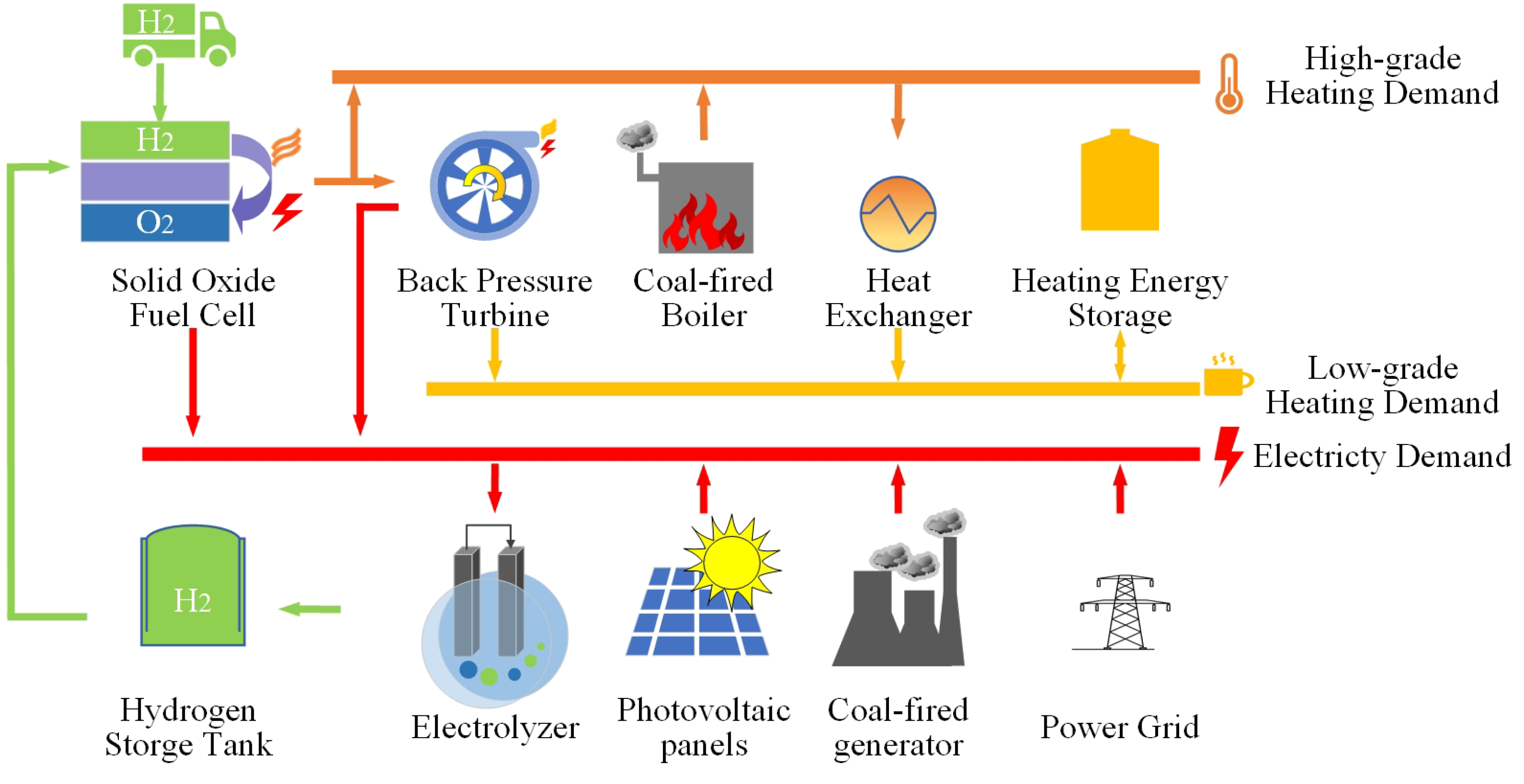
2.4. Operation Constraints of HIES

Operation constraints of HIES are shown in (16)–(22).
p k , t F C τ = η F C , e m k , t F C , p k , t F C P ¯ k F C ,
g k , t F C = η F C , g m k , t F C ,
p k , t B P T = η B P T , e g k , t F C , B P T , p k , t B P T P ¯ k B P T ,
g k , t B P T , o u t = η B P T , g g k , t F C , B P T ,
m k , t E L = η E L p k , t E L τ , p k , t E L P ¯ k E L ,
g k , t + 1 H E S = g k , t H E S + g k , t i o , g k , t H E S G ¯ k H E S ,
m k , t + 1 H S = m k , t H S + m k , t i o , m k , t H S M ¯ k H S ,
where P ¯ k F C is the nominal power of SOFC in year k. η F C , e and η F C , g are the energy conversion coefficients of hydrogen to electrical energy and hydrogen to heating energy in SOFC, respectively. η B P T , e is energy conversion efficiency of heating energy to electrical energy in BPT, and η B P T , g is energy conversion efficiency of high-grade heating energy to low-grade heating energy in BPT. η E L is the power to hydrogen conversion coefficient of the electrolyzer. g k , t H E S is the remaining heating energy in the HES at stage t in year k, and m k , t H S is the remaining hydrogen in the hydrogen tank. Equations (21) and (22) describe the energy dynamics of storage devices.

2.5. Operation Constraints of CES

Operation constraints of CES are shown in (23)–(25).
p k , t C G τ = η C G m k , t C G , p k , t C G P ¯ k C G ,
g k , t C B = η C B m k , t C B , g k , t C B G ¯ k C B ,
g k , t C B = g k , t C B , d + g k , t C B , H E X ,
where η C G is the coal to power conversion coefficient of the CG, η C B is the coal to heating energy conversion coefficient of the CB, and g k , t C B is the heating energy generated by the CB.

3. Solution Methodology

With the capacity expansion planning problem of (1)–(25), the low-carbon transition of the industrial energy system can be achieved. However, the carbon dioxide peaking before the given time (e.g., 2030, as the goal proposed by Chinese government) cannot be ensured. In this paper, the Pettitt test [6] is introduced as constraints of carbon emissions trends in annual scale, as follows:
c k = t = 1 T ( β e l e p k , t G β e l e p k , t U + β C m k , t C ) ,
l k = m = 1 k n = m + 1 K s g n ( c n c m ) , k = 2 , . . . , K , max 1 s Y | l s | = max 1 s K | l s | ,
where c k is the carbon emission of the industrial energy system in k, and it is calculated by (26). β e l e and β C are emission factors of power grid and coal, respectively. l k is a statistical value used in the Pettitt test, which can be calculated by (27), and the inflection point of data series c k is at the point where the absolute value of l k is maximum. m is an index from 1 to k, n is an index from m + 1 to K, s is an index from 1 to K, and Y is the given year achieving carbon dioxide peaking. This way, the peak value of annual carbon emissions would appear before year Y in the whole planning horizon, thus ensuring the carbon dioxide peaking before the given time.
Then, Equation (27) is linearized by using 0–1 variables, replacing the operation s g n ( ) through the large M method; thus, the problem (1)–(27) can be converted as a mixed-integer linear programming problem and solved with the weather data and demand profiles.

4. Numerical Testing Results

The numerical testing is based on a practical industrial park in Jiangsu with 6 km 2 . The CES installed in the initial state consists of a coal-fired generator (62 MW, which will be retired after 15 years) and a coal-fired boiler (69 MW, which will be retired after 5 years). The TOU power price λ k , t G was obtained from [2] and is shown in Table 1. The feed-in tariff λ k U is assumed to be 0, and the hydrogen price is assumed to be RMB 20/kg [7]. The heat exchange efficiency μ is assumed to be 0.95 [8]. The limit area of implementing PV panels is 50 hm 2 . The energy conversion coefficients of the SOFC, η F C , e and η F C , g are assumed to be 10 kWh/kg and 20 kWh/kg, respectively [9]. The energy conversion coefficients of the CG and CB, η C G and η C B , are assumed to be 2.475 kWh/kg and 3.106 kWh/kg, respectively [10,11]. The energy conversion coefficients of the BPT, η B P T , e and η B P T , g , are assumed to be 0.23 and 0.72, respectively [8]. The capital expenditure of equipment utilized in the HIES and CES is listed in Table 2. Note that the capital expenditure of the SOFC is considered to change as time goes by [12], since it is the key energy conversion device in the HIES. Other parameters are obtained from [2]. The test is performed on a planning horizon with 10 years, from 2022 to 2032. The emission peaking year, Y, is assumed to be the 8th year (2030). The weather conditions were obtained from [13]. The demand profiles were obtained based on the historical data of the industrial park and increasing year by year. In addition, we assume that the load data will grow at a rate of 3.7% per year. The total demand for electricity, steam, and heat in the first year of the industrial park was 195,831MWh, 189,177 MWh and 319,940 MWh respectively, and there was no obvious demand fluctuation throughout the year. The capacity expansion planning problem of (1)–(27) is solved by the Gurobi solver with the given weather data and demand profiles.

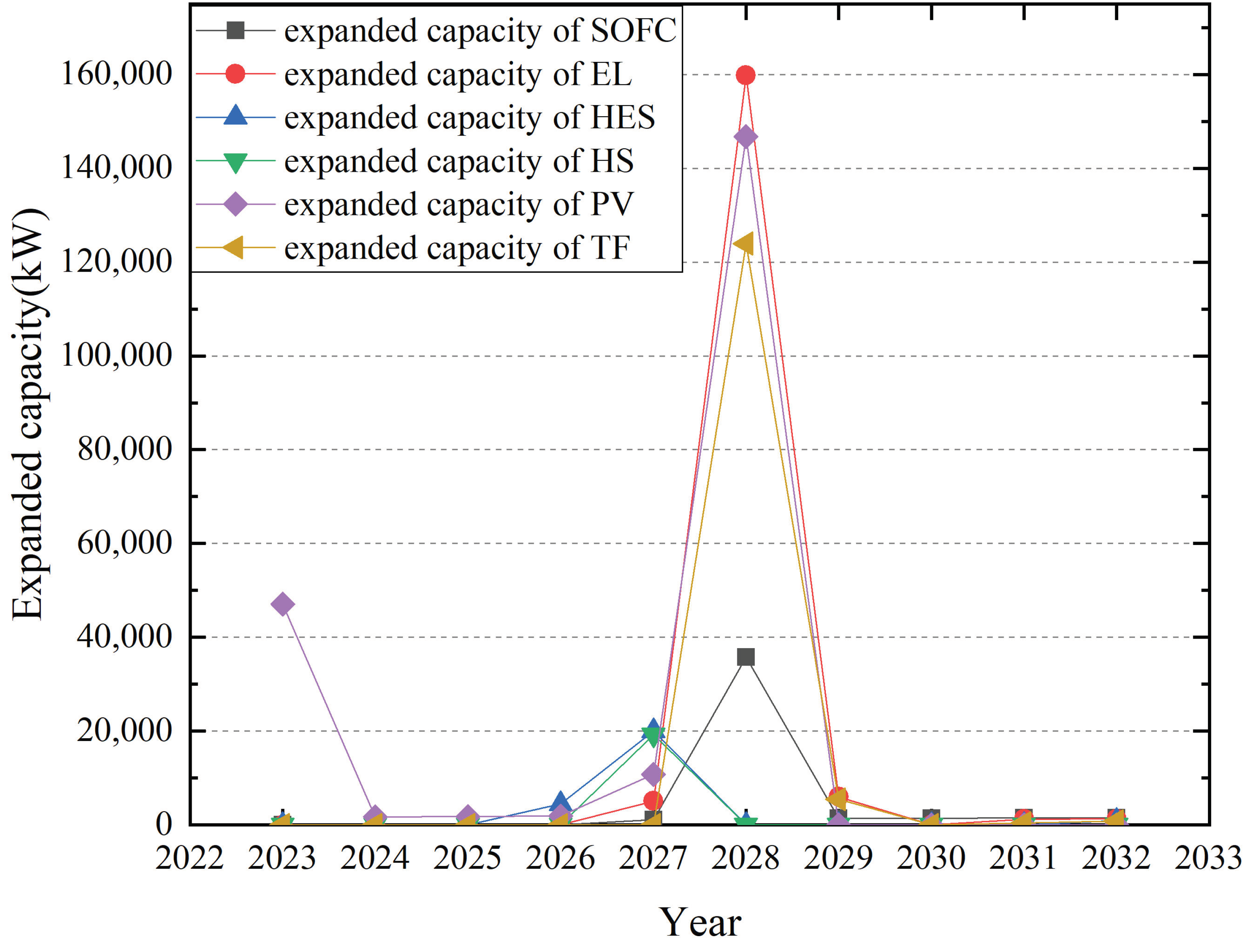
4.1. Optimization Results

By solving the problem with the given data, the annual costs and emissions are shown in Figure 2, and capacity expansion strategies of the energy devices are shown in Figure 3. As can be seen in Figure 2, the carbon dioxide peaking can be achieved before 2030 (in 2029), which proves that the developed method can supply a feasible carbon dioxide peaking strategy of the industrial energy system. Meanwhile, the change in operation costs is not particularly significant, and is decreasing between most years. It means that the developed carbon dioxide peaking strategy has economic feasibility. On the other hand, the costs and emissions have a significant change from 2027 to 2028, as shown in Figure 2. Since the CB is retired in this year, the energy supply of the HIES cannot meet the energy demand, which leads to a great capacity expansion demand, as shown in Figure 3. The capacities of the EL, PV panels, and SOFC have a significant expansion, which make the capital cost increase and carbon emissions decrease. It can be seen that large-scale investment in hydrogen energy equipment may appear around 2028, which is due to the SOFC still being relatively high, but there is an expected reduction in the investment cost caused by photovoltaic investment in the first year, on the one hand due to its lower economic cost, and on the other hand due to its ability to produce hydrogen in combination with electrolyzers.Although the good expectation for the popularization of hydrogen equipment does not significantly accelerate the speed of procurement of hydrogen equipment in industrial parks, it can effectively increase the willingness of industrial parks to configure hydrogen-energy-related equipment, especially photovoltaic, which can be used to provide electricity for hydrogen production, and may even include electrolytic cells with competitive prices.

4.2. Sensitivity Analysis

To investigate the effect of the carbon dioxide peaking time and emission reduction requirements on the performance of the developed method, a sensitivity analysis is implemented in this section. First, the capacity expansion planning problem is solved with different carbon dioxide peaking time Y, and the results are shown in Table 3. Note that for evaluating the economic benefits of the developed carbon dioxide peaking strategy, a strategy using CES for supplying energy and purchasing emission allowance based on emission trading schemes [2] for satisfying emissions reduction targets is used. The annual and overall emissions of the two strategies are same, and the costs of the strategy with purchasing allowance are also shown in Table 3.
The results show that for achieving the same emission reduction, the cost of the strategy based on purchasing allowance is significantly more than that of the strategy based on the HIES, even three times in the case with carbon dioxide peaking before 2030 or 2028. It means the developed strategy based on the HIES has a significant economic benefit. On the other hand, with the given peaking time Y changing from 2030 to 2024, the emission peak slightly decreases and the overall cost slightly increases. It means that the developed method can supply different carbon dioxide peaking strategies for different peaking time, with a little economic sacrifice.
Second, to investigate the effect of different emission reduction targets on the performance of the developed method, the cases with different emission reduction targets in 2030 are calculated and the results are shown in Table 4. Note that the emission targets in 2030 mean that the emission in 2030 should be lower than the given percentage in the first column of the emission in 2022. As shown in Table 4, with the developed method, when the emission in 2030 drops by 64.22%, the overall cost only rises by 0.41%. As a comparison, the cost of the strategy based on purchasing allowance rises by 40.43% for achieving the same emissions in 2030. The results show that the different emission targets can be obtained by the developed method with a little economic sacrifice, and the economic benefit of the strategy obtained by the developed method is significant better than the strategy based on purchasing emission allowance.

5. Conclusions

This paper focuses on the long-term capacity expansion planning problem of the HIES for carbon dioxide peaking. The problem is formulated as a mixed-integer linear programming problem, and the target of carbon dioxide peaking is considered as a constraint in this problem. The numerical results show that the target can be achieved while ensuring the economic performance to some extent with the developed method. The targets of carbon dioxide peaking before different years can be achieved through the strategies obtained by the developed method, and the different emission targets can be achieved with a little economic sacrifice. The strategy based on purchasing emission allowance is also calculated for comparison, and its overall cost is three times more than the cost of the strategy obtained by the developed method, while the emissions of the two strategies are same. It means that the economic performance of the developed method is obviously better than the strategy based on purchasing allowance. Meanwhile, different emission reduction targets will affect the planning results, and determining appropriate emission reduction targets can realize the balance between economic benefits and carbon reduction benefits. For example, in this paper, the carbon emission reduction of industrial parks increased by 64.22%, while increasing the total cost by only 0.41%. Thus, the developed capacity expansion planning method of the hydrogen-enabled industrial energy system is a promising way to achieve the carbon dioxide peaking of industrial energy systems. In our future work, we will further study and explore the feasibility of SOFCs using carbon fuels to participate in energy system expansion planning, as well as the further impact of HIESs on the local economy and industrial competitiveness.

Author Contributions

Conceptualization, K.Z. and X.D.; methodology, C.L. and Y.Z.; writing—original draft preparation, X.D.; writing—review and editing, K.Z.; funding acquisition, K.L. All authors have read and agreed to the published version of the manuscript.

Funding

This work was funded by the National Natural Science Foundation of China under Grant 61903293.

Data Availability Statement

The data presented in this study will be made available on request.

Conflicts of Interest

Author Kai Zheng is employed by Guoneng Xinjiang Ganquanbao Comprehensive Energy Co., Ltd. Author Chaofeng Li is employed by Guoneng Zhishen Control Technology Co., Ltd. Authors Xiangxiang Dong, Yanling Zhao, and Kun Liu received research grants from the National Natural Science Foundation of China under grant no. 61903293. The remaining authors declare that the research was conducted in the absence of any commercial or financial relationships that could be construed as potential conflicts of interest. The funders were not involved in the study design, collection, analysis, interpretation of data, the writing of this article, or the decision to submit it for publication.

Abbreviations

The following abbreviations are used in this manuscript:
HIESHydrogen-enabled industrial energy system
CESCoal-driven energy system
SOFCSolid oxide fuel cell
HSHydrogen storage tank
ELElectrolyzer
BPTBack-pressure turbine
HESHeating energy storage
HEXHeat exchanger
PVPhotovoltaic
CBCoal-fired boiler
CGCoal-fired generator
TOUTime-of-use

References

  1. Tong, Y.; Wang, K.; Liu, J.; Zhang, Y.; Gao, J.; Dan, M.; Yue, T.; Zuo, P.; Zhao, Z. Refined assessment and decomposition analysis of carbon emissions in high-energy intensive industrial sectors in China. Sci. Total Environ. 2023, 872, 162161. [Google Scholar] [CrossRef] [PubMed]
  2. Dong, X.; Wu, J.; Xu, Z.; Liu, K.; Guan, X. Optimal coordination of hydrogen-based integrated energy systems with combination of hydrogen and water storage. Appl. Energy 2022, 308, 118274. [Google Scholar] [CrossRef]
  3. Wang, T.; Zhang, H.; Zhang, Y.; Wang, H.; Lyu, J.; Yue, G. Efficiency and emissions of gas-fired industrial boiler fueled with hydrogen-enriched nature gas: A case study of 108 t/h steam boiler. Int. J. Hydrogen Energy 2022, 47, 28188–28203. [Google Scholar] [CrossRef]
  4. Chang, Y.; Wan, F.; Yao, X.; Wang, J.; Han, Y.; Li, H. Influence of hydrogen production on the CO2 emissions reduction of hydrogen metallurgy transformation in iron and steel industry. Energy Rep. 2023, 9, 3057–3071. [Google Scholar] [CrossRef]
  5. Lin, J.; Cai, R. Optimal planning for industrial park-integrated energy system with hydrogen energy industry chain. Int. J. Hydrogen Energy 2023, 48, 19046–19059. [Google Scholar] [CrossRef]
  6. Ahmadi, F.; Nazeri Tahroudi, M.; Mirabbasi, R.; Khalili, K.; Jhajharia, D. Spatiotemporal trend and abrupt change analysis of temperature in Iran. Meteorol. Appl. 2018, 25, 314–321. [Google Scholar] [CrossRef]
  7. Dong, X.; Liu, Y.; Xu, Z.; Wu, J.; Liu, J.; Guan, X. Optimal Scheduling of Distributed Hydrogen-based Multi-Energy Systems for Building Energy Cost and Carbon Emission Reduction. IEEE Int. Conf. Autom. Sci. Eng. 2020, 2020, 1526–1531. [Google Scholar] [CrossRef]
  8. Mu, C.; Ding, T.; Qu, M.; Zhou, Q.; Li, F.; Shahidehpour, M. Decentralized optimization operation for the multiple integrated energy systems with energy cascade utilization. Appl. Energy 2020, 280, 115989. [Google Scholar] [CrossRef]
  9. Staffell, I. Zero carbon infinite COP heat from fuel cell CHP. Appl. Energy 2015, 147, 373–385. [Google Scholar] [CrossRef]
  10. Bartela, Ł.; Skorek-Osikowska, A.; Kotowicz, J. An analysis of the investment risk related to the integration of a supercritical coal-fired combined heat and power plant with an absorption installation for CO2 separation. Appl. Energy 2015, 156, 423–435. [Google Scholar] [CrossRef]
  11. Zhao, S.; Ge, Z.; Sun, J.; Ding, Y.; Yang, Y. Comparative study of flexibility enhancement technologies for the coal-fired combined heat and power plant. Energy Convers. Manag. 2019, 184, 15–23. [Google Scholar] [CrossRef]
  12. Whiston, M.M.; Azevedo, I.M.; Litster, S.; Samaras, C.; Whitefoot, K.S.; Whitacre, J.F. Meeting US solid oxide fuel cell targets. Joule 2019, 3, 2060–2065. [Google Scholar] [CrossRef]
  13. Pfenninger, S.; Staffell, I. Renewables.ninja. Available online: https://www.renewables.ninja/ (accessed on 1 June 2022).
  14. Liu, J.; Xu, Z.; Wu, J.; Liu, K.; Guan, X. Optimal planning of distributed hydrogen-based multi-energy systems. Appl. Energy 2021, 281, 116107. [Google Scholar] [CrossRef]
  15. Al-Khori, K.; Bicer, Y.; Koç, M. Comparative techno-economic assessment of integrated PV-SOFC and PV-Battery hybrid system for natural gas processing plants. Energy 2021, 222, 119923. [Google Scholar] [CrossRef]
  16. Kler, A.; Stepanova, E.; Maksimov, A. Investigating the efficiency of a steam-turbine heating plant with a back-pressure steam turbine and waste-heat recovery. Thermophys. Aeromechanics 2018, 25, 929–938. [Google Scholar] [CrossRef]
Figure 1. The industrial energy system, including HIES and CES.
Energies 17 03400 g001
Figure 2. Annual costs and emissions.
Energies 17 03400 g002
Figure 3. Capacity expansion strategies.
Energies 17 03400 g003
Table 1. TOU power price.
Time (hour)Price (RMB/kWh)
22:00–6:000.298
6:00–8:00, 11:00–18:00, 21:00–22:000.593
8:00–11:00, 18:00–21:001.021
Table 2. Unit capital price of equipment [14].
EquipmentCost
SOFC455,539–5050 RMB/kW [12,15]
ElectrolyzerRMB 2100/kW
Back-pressure turbineRMB 406.2/kW [16]
Hydrogen storage tankRMB 3385/kg
Heating energy storageRMB 33.85/kWh
Coal-fired generatorRMB 13,464/kW [10]
Coal-fired boilerRMB 1292/kW [11]
PV panelsRMB 900/ m 2
Table 3. Overall costs and emissions with different peaking time.
Peaking TimeOverall Cost (RMB)Costs of Purchasing Allowance (RMB)Emission Peak (kg)
20303.191 × 1099.870 × 1095.819 × 1010
20283.191 × 1099.870 × 1095.819 × 1010
20263.238 × 1095.765 × 1095.611 × 1010
20243.248 × 1095.902 × 1095.218 × 1010
Table 4. Overall costs and emissions with different emission targets in 2030.
Emission Targets in 2030 Compared with 2022Overall Cost (RMB)Costs of Purchasing Allowance (RMB)Emission Peak (kg)Emission in 2030 (kg)
100%3.191 × 1099.870 × 1095.819 × 10103.516 × 1010
75%3.191 × 1099.870 × 1095.819 × 10103.516 × 1010
50%3.197 × 1091.151 × 10105.819 × 10102.516 × 1010
25%3.204 × 1091.386 × 10105.819 × 10101.258 × 1010
Disclaimer/Publisher’s Note: The statements, opinions and data contained in all publications are solely those of the individual author(s) and contributor(s) and not of MDPI and/or the editor(s). MDPI and/or the editor(s) disclaim responsibility for any injury to people or property resulting from any ideas, methods, instructions or products referred to in the content.

