Review

Enhancing Electrode Efficiency in Proton Exchange Membrane Fuel Cells with PGM-Free Catalysts: A Mini Review

by
Ioanna Martinaiou
* and
Maria K. Daletou
*
Foundation of Research and Technology, Hellas—Institute of Chemical Engineering Sciences, FORTH/ICEHT, Stadiou Str., Platani Rion, GR-26504 Patras, Greece
*
Authors to whom correspondence should be addressed.
Energies 2024, 17(14), 3443; https://doi.org/10.3390/en17143443
Submission received: 2 June 2024 / Revised: 6 July 2024 / Accepted: 9 July 2024 / Published: 12 July 2024
(This article belongs to the Section D2: Electrochem: Batteries, Fuel Cells, Capacitors)

Abstract

:
Proton Exchange Membrane Fuel Cells (PEMFCs) represent a promising green solution for energy production, traditionally relying on platinum-group-metal (PGM) electrocatalysts. However, the increasing cost and limited global availability of PGMs have motivated extensive research into alternative catalyst materials. PGM-free oxygen reduction reaction (ORR) catalysts typically consist of first-row transition metal ions (Fe, Co) embedded in a nitrogen-doped carbon framework. Key factors affecting their efficacy include intrinsic activity and catalyst degradation. Thus, alternative materials with improved characteristics and the elucidation of reaction and degradation mechanisms have been the main concerns and most frequently explored research paths. High intrinsic activity and active site density can ensure efficient reaction rates, while durability towards corrosion, carbon oxidation, demetallation, and deactivation affects cell longevity. However, when moving to the actual application in PEMFCs, electrode engineering, which involves designing the catalyst layer, and other critical operational factors affecting fuel cell performance play a critical role. Electrode fabrication parameters such as ink formulation and deposition techniques are thoroughly discussed herein, explicating their impact on the electrode microstructure and formed electrochemical interface and subsequent performance. Adjusting catalyst loading, ionomer content, and porosity are part of the optimization. More specifically, porosity and hydrophobicity determine reactant transport and water removal. High catalyst loadings can enhance performance but result in thicker layers that hinder mass transport and water management. Moreover, the interaction between ionomer and catalyst affects proton conductivity and catalyst utilization. Strategies to improve the three-phase boundary through the proper ionomer amount and distribution influence catalyst utilization and water management. It is critical to find the right balance, which is influenced by the catalyst–ionomer ratio and affinity, the catalyst properties, and the layer fabrication. Overall, understanding how composition and fabrication parameters impact electrode properties and behaviour such as proton conductivity, mass transport, water management, and electrode–electrolyte interfaces is essential to maximize electrochemical performance. This review highlights the necessity for integrated approaches to unlock the full potential of PGM-free materials in PEMFC technology. Clear prospects for integrating PGM-free catalysts will drive cleaner and more cost-effective, sustainable, and commercially viable energy solutions.

1. Introduction

In today’s industrial societies, energy demands are continually escalating, presenting increasingly challenging barriers to overcome. The predominant source of energy “production” largely stems from fossil fuels. The emissions of carbon dioxide into the atmosphere intensify the greenhouse effect, exerting a significant role in climate change. Urgent action is required to transition towards global environmental sustainability, ensuring ongoing prosperity. The imperative for clean and sustainable energy production is undeniable. However, addressing the growing need for renewable energy and reducing CO2 emissions presents a significant challenge. It necessitates the development of eco-friendly systems, including buildings with low environmental impact, solar power systems, and hydrogen-powered vehicles such as cars, buses, and other transport machinery [1]. Hydrogen is appealing especially when reacted with air in a fuel cell electrochemical device to produce water and generate electricity.
Proton exchange membrane fuel cells are leading the way in global decarbonization efforts. Their environmentally friendly operation, quick refueling capabilities, low operating temperatures, and high energy density make them an advanced technology suitable for various applications. PEMFCs have been considered for stationary, transit, and portable applications and can achieve efficiencies as high as 65% [1]. The anode and cathode, two porous electrodes, are separated by a polymer electrolyte membrane (PEM) in these devices. Rare platinum (Pt) and Pt-alloys are the state-of-the-art catalysts for the necessary redox processes (oxygen reduction, ORR at the cathode, and hydrogen oxidation, HOR at the anode). HOR has comparatively fast kinetics, and therefore less catalyst is needed. On the other hand, ORR is a sluggish reaction that requires large quantities of platinum-group-metal (PGM) catalysts due to the formation of different intermediates [2].
Commercial PEMFC products are currently available, with China having over 6000 FCEVs, and U.S. having >10,000 FCEVs sold or leased by May 2021 [1]. However, the major barrier to widespread deployment is the cost of this technology. The penetration of PEMFCs into commercial markets is anticipated to increase, driven by economies of scale that lower costs as sales rise. However, the cost of PGM catalysts may increase with higher sales. Currently, the expense of producing a PEMFC stack is about $75 per kW when manufactured in large quantities. The catalytic layers account for more than 40% of this total cost because they utilize valuable PGMs as catalysts [1]. Replacing unsustainable noble-metal-based materials with PGM-free catalysts for the ORR is crucial to improve the material sustainability and commercial viability of PEMFCs. The most promising representative of PGM-free ORR catalysts are made from first-row transition metal ions (Fe, Co, Mn, Ni) combined with nitrogen and carbon precursors, which are heat-treated at high temperatures (typically above 800 °C) [3]. This process results in highly active metal-nitrogen-doped carbon (M–N–C) catalysts with ORR activities approaching those of Pt-based catalysts in both acidic and alkaline electrolytes. Particularly, catalysts with atomically dispersed MNx/C structures exhibit significant ORR activity in both half-cell and membrane electrode assembly (MEA) operations [4,5]. Interestingly, several of these catalysts present initial activity close to or even more than 0.044 A cm−2 @ 0.9 VIR-free [4,6,7], a target established by the U.S. Department of Energy (DOE) for PGM-free catalysts. Nevertheless, most MNx/C catalysts show inadequate stability, especially when exposed to the high voltage (0.6–1.2 V), high temperature (60–80 °C), and highly acidic environments (pH < 1) that characterize PEMFC operating conditions [8]. In this respect, additional research is essential to develop electrocatalysts with superior performance. This can be accomplished by enhancing the intrinsic activity of the active sites while further promoting their density, utilization, and durability.
The standard approach in order to prepare PEMFC electrodes includes wet ink deposition techniques to apply the membrane electrolyte or the diffusion media with a mixture of an ionomer and the Pt-based catalyst. Nevertheless, this process frequently results in uncontrolled mixing and deposition, which leaves electrodes with little catalyst utilization and complicated routes for the transport of protons, electrons, and oxygen, ultimately reducing the performance. Recent improvements in terms of activity [9], stability [10], and degradation mechanisms [11] have been outlined in previous reviews. The current study addresses a critical gap in the field by comprehensively reviewing the integration of PGM-free catalysts into PEMFC electrodes. This work sheds light on several approaches and highlights the importance of optimizing electrode and cell parameters for enhanced performance. Understanding the intricate interplay between electrode structure, operating conditions, and PGM-free catalyst properties is essential. Achieving higher power density would pave the way for more sustainable, cost-effective, and efficient PEMFCs, enabling their wider-scale deployment.
In this respect, the most important aspects regarding the activity and durability of the M–N–C catalysts are briefly summarized herein, followed by a detailed description of the role of electrode manufacturing and other critical parameters influencing fuel cell performance. Electrode fabrication parameters such as ink formulation, deposition techniques, and catalyst–ionomer affinity are discussed, elucidating their impact on electrode microstructure and electrochemical performance. When transitioning to actual PEMFC application, key factors affecting the performance and durability include overall electrode properties such as proton conductivity, water management, and electrode–electrolyte interfaces. The current review summarizes the efforts to integrate PGM-free catalysts into efficient cathodic electrodes and emphasizes the necessity for combined approaches to unlock the full potential of these materials in PEMFC technology.

2. Platinum Group Metal (PGM)–Free Electrocatalysts

2.1. Progress on Metal-Nitrogen-Carbon (M–N–C) Catalysts

Oxygen reduction to water is a fundamental process across all respiratory organisms on Earth. In eukaryotes, cytochrome c oxidase (CcO) plays a pivotal role in catalyzing this reaction, which has spurred interest in Fe–N–C ORR catalyst research [12]. The research on PGM-free catalysts using cost-effective alternatives such as Fe, Co, Ni, etc., has been intensive in the past few decades. Various approaches have been investigated, including non-pyrolyzed transition metal macrocycles, both pyrolyzed and non-pyrolyzed conductive polymer-based complexes, transition metal chalcogenides, metal oxides/nitrides/carbides, and pyrolyzed non-precious M–N–C catalysts (where Me = Fe, Ni, Co, etc.) [9]. An overview of the PGM-free catalysts’ from their discovery [13,14,15] is illustrated in Figure 1 including the most recent pioneering works in this field [16,17,18,19,20,21]. The current review focuses on pyrolyzed materials containing metal precursors (M–N–C catalysts), since they constitute the largest class of ORR PGM-free catalysts and exhibit significantly higher activity in acidic environment compared to their metal-free counterparts.
The initial preparation method of M–N–C catalysts involved the use of high specific surface area carbon blacks functionalized with an organic molecule rich in nitrogen (e.g., 1,10 phenanthroline) and metal salts (e.g., iron acetate). This synthesis approach is beneficial for creating high-performance Fe–N–C materials used in PEMFCs, as demonstrated by achieving significant current densities comparable to those obtained with traditional platinum-based cathodes. However, one drawback of this method is the presence of a relatively high amount of inactive carbon atoms in the catalyst, which prompted further research into alternative synthesis methods that do not rely on pre-existing carbon supports. Thus, the scientific community focused on precursors of transition metal salts with metal–organic frameworks (MOFs) or polyaniline (PANI) and analogues (Figure 2) [22] to form the carbon and nitrogen network. Additional to the above, high surface area supports have been used to control the catalyst morphology, as well as sacrificial templates to ensure the desired porosity.

2.1.1. Polyaniline and Analogues

PANI, polypyrrole, polyphenylenediamine, and similar electroconductive polymers are notable for their low cost and rich nitrogen (N) content, with approximately 1 N atom for every 5 or 6 carbon (C) atoms. Nanostructured PANI tends to create a hierarchical pore structure and isolated active sites at the atomic level, characterized by high density and electrical conductivity. This is facilitated by the high ordering degree in composition and structure, along with a uniform distribution of nitrogen sources [23]. Heat treatment of these N-containing polymer precursors enhances their oxygen reduction activity [22]. Zelenay and coworkers first reported results on non-pyrolyzed Co-based polypyrrole systems [24], while later shifted focus towards high-temperature systems [25]. The exact precursors’ composition and synthesis procedure can differentiate the catalyst properties and thus activity. Zhang et al., successfully developed a pyrrole-type FeN4 structure through ammonia pyrolysis of a polyaniline-based mixture [26]. The catalyst demonstrated significantly enhanced intrinsic activity, presenting a peak power density of up to 700 mW/cm2, attributed to the high-purity FeN4 sites and the presence of a large number of mesopores that increased the utilization of active sites. Other attempts have proven that the addition of sulfur in the structure can significantly enhance catalytic activity [27,28]. The high nitrogen content in PANI-derived PGM-free catalysts contributes to their significant ORR activity by providing ample active sites. An efficient hierarchical porous structure enhances the utilization of these sites. Thus, adopting appropriate synthesis methods to boost the density of active sites and develop a hierarchical pore structure in PANI-based ORR catalysts is essential.
In this respect, an interesting approach, namely “shape fixing via salt recrystallization”, was introduced by Ding et al. [29]. The method involves creating a 3D PANI–Fe network by encasing it in recrystallized NaCl before pyrolyzing at 900 °C. Through this process, a more controllable highly porous structure with abundant active sites was obtained. The catalyst presented an open-circuit voltage (OCV) of 0.85 V and a maximum power density of 0.6 W/cm2 in a single fuel cell test. This technique enhances mass transport and catalyst utilization, offering a promising approach for developing high-performance, non-precious-metal PEMFC cathode catalysts.
In another approach, Zamani et al., developed an iron–polyaniline/polyacrylonitrile nanofiber catalyst via electrospinning and subsequent heat treatments [30]. Its enhanced performance was attributed to the porous structure, coupled with the augmented presence of surface pyridinic and graphitic nitrogen species. The introduction of phenanthroline, both as an additional N precursor and as a pore-forming agent, resulted in a distinctive graphene-based nitrogenous electrocatalyst that achieved values of 1.06 W/cm2 (at 0.46 V) and 0.38 W/cm2 (at 0.56 V) with O2 and air cathode feed, respectively [31]. Due to the high nitrogen content and the ability of the micropores to host active sites, PGM-free catalysts derived from PANI and their analogues can exhibit high ORR activity. Therefore, proper synthesis strategies should be pursued to effectively increase the density of active sites and, at the same time, improve their utilization through the design of the catalyst pore structure.

2.1.2. High Surface-Area Supports or Sacrificial Template Method

Carbon-based materials are many times applied as supports for the developed structures, capitalizing on their high surface area. A nice example was presented by Wu et al., that utilized Ketjen Black as a support to develop a FeCo–PANI/C catalyst [17]. Fuel cell evaluations revealed a peak power density of 0.55 W/cm2 at 0.4 V, showcasing robust durability with stable performance over 700 h under potential hold at the same voltage. However, operational voltages exceeding 0.6 V resulted in significant performance degradation. In a different mode, to eliminate the need for a carbon support, silica-based materials are most commonly selected as the sacrificial template, since their subsequent removal from the final structure can generate an internal pore network [32]. The structure of the hard template induces a large surface area and the desired porous structure, allowing controlled porosity to be achieved by carefully adjusting the quantity, process, and materials used. Serov et al., presented a class of non-PGM catalysts from the Fe–N–C family, synthesized using a sacrificial support method with iron nitrate and carbendazim (CBDZ) precursors [33]. The process involved high-temperature pyrolysis followed by etching to create a “self-supported” open-frame morphology. The catalysts exhibited exceptional ORR activity and a maximum power density of 0.56 W/cm2 due to improved mass transfer. Both heat treatment temperature and Fe-to-CBDZ ratio significantly influence the final catalytic performance. Similarly, Wei’s group reported a Fe–N–C–SiO2–ZnCl2 catalyst, synthesized using ZnCl2 and silica templating, which demonstrates exceptional ORR activity in both alkaline and acidic media [34]. The catalyst achieved a maximum power density of 0.48 mW/cm2 with a loading of just 0.5 mg/cm2. The innovative synthesis process creates a 3D structure with a high density of active sites, enhancing mass transport during the ORR process. This catalyst’s performance in PEMFC is comparable to Pt-based catalysts, marking a significant step toward practical applications. This work underscores the importance of high-density active sites and ultra-thin catalyst layers for improving fuel cell efficiency and paves the way for the commercialization of advanced Fe–N–C catalysts.
Additionally, Mun et al., proposed an interesting “soft-template” approach to further enhance ORR activity [35]. The organic N and Fe precursor (a Fe–phenanthroline complex) was mixed in trimethylbenzene and a surfactant (Pluroni127). The silica formation took place together with the casting, and thus the catalyst precursor was simultaneously incorporated in the matrix. Despite templating, this study introduced a novel strategy to enhance the ORR activity of Fe–N–C catalysts by tuning the electronic properties of a single FeN4 site through sulfur doping. Electron-withdrawing oxidized sulfur functionalities increased ORR activity while electron-donating thiophene-like sulfur functionalities decreased it. Overall, the PGM-free electrocatalysts synthesized using the sacrificial template approach have the potential to provide exceptional ORR activity in fuel cell tests, thanks to the better control over the formed pore structure leading to improved catalyst utilization and mass transfer.

2.1.3. Metal–Organic Frameworks (MOFs)

Metal–organic frameworks (MOFs), especially Zn-rich zeolitic imidazole frameworks (ZIFs), are ideal precursors for PGM-free ORR catalysts. MOFs promote the creation of high-density, well-dispersed single-atom active sites via a straightforward thermal treatment. For example, ZIF-8, which includes zinc centers with nitrogen-rich organic ligands, can ensure uniform nitrogen distribution within the carbon framework, facilitating binding to the metal during chelation or pyrolysis. This process produces highly ordered porous crystalline structures that increase the density of atomically dispersed MNx/C active sites and minimize the formation of inactive metal particles. These attributes make MOFs highly effective for developing high-performance, PGM-free ORR catalysts.
In 2011, Dodelet and co-workers investigated the use of ZIF-8 as a host for Fe and N precursors (iron(II) acetate and 1,10-phenanthroline) to create Fe–N–C catalysts [16]. Unlike previous Fe–N–C catalysts that used carbon black supports, the new catalyst was synthesized by ball-milling the precursors and performing two stages of pyrolysis. This method resulted in a catalyst exhibiting at that time the highest volumetric activity reported for PGM-free ORR catalysts in PEMFCs, achieving a peak power density of 0.91 W/cm2, which is comparable to platinum-based cathodes. Enhanced mass-transport properties, evidenced by SEM and TEM imaging, show the interconnected porous structure of the new catalyst, contributing to its superior performance. The study highlighted the potential of these Fe-based catalysts as a viable alternative to Pt-based catalysts. MOF-based synthesis methods produce catalysts with enhanced performance, largely due to the high density of MNx coordination sites that persist after high-temperature pyrolysis [36]. Consequently, research has focused on increasing the density and accessibility of active sites [37].
In 2015, Shui et al., introduced an innovative method to produce highly efficient nanofibrous PGM-free catalysts for the oxygen reduction reaction (ORR) [18]. Their approach involved electrospinning a polymer solution containing ferrous organometallics and ZIF-8, followed by thermal activation. The resulting catalyst featured a carbon nanonetwork structure composed of microporous nanofibers adorned with uniformly distributed high-density active sites. Tests conducted in single cells demonstrated exceptional performance, achieving unprecedented volumetric activities of 3.3 A/cm3 at 0.9 V or extrapolated to 450 A/cm3 at 0.8 V, marking a record high in the field at that time. Although the fuel cell durability was assessed for only 20 h, enhanced stability was noted. The study highlighted the critical role of ZIF-8 in optimizing catalyst morphology, surface properties, and nitrogen content, thereby influencing ORR performance. Their strategy offered a PGM-free catalyst with tailored nanonetwork architecture, essential for advanced PEM fuel cell applications and potentially other carbon-based catalytic systems requiring efficient mass transport to active sites.
In another work, a highly active and stable catalyst was prepared with uniform atomic iron distribution using Fe-doped ZIF-8 as a precursor [38]. Unlike traditional methods, this approach involves a single-step thermal conversion without the need for post-treatments like acid leaching or additional heating. Crucially, maintaining an oxygen-free environment during the precursor preparation ensures uniform Fe distribution within the porous carbon matrix, preventing the formation of inactive iron aggregates. The catalyst exhibits exceptional ORR performance with a high half-wave potential (0.82 V vs. RHE), low H2O2 yield (<1%), and sufficient stability during potential cycling in acidic conditions. This innovation reduces the performance gap between non-precious-metal catalysts and Pt/C catalysts in challenging acidic environments.
Although these catalysts have emerged as promising alternatives to conventional Pt/C electrocatalysts, the fact that iron tends to aggregate during high-temperature treatment, potentially covering the active FeNx sites, impairs the performance. To address this issue, Wang et al., synthesized a Fe–N–C catalyst with stable FeNx species uniformly dispersed in hollow carbon frameworks [39]. These were synthesized via the in situ growth of Fe-doped ZIFs on g-C3N4, followed by pyrolysis and acid etching. The resulting catalysts demonstrated excellent ORR activity, high methanol resistance, and long-term stability in alkaline solutions, outperforming traditional Pt/C catalysts. This performance was attributed to the robust structure and uniform dispersion of active sites.
Sun and co-workers presented an innovative carboxylate-assisted strategy to significantly enhance the mass activity of Fe–N–C catalysts derived from ZIF-8 [19]. By introducing carboxylates, the synthesis process increases the density of accessible active sites and incorporates entangled carbon nanotubes, which contribute to higher mesoporosity. These structural improvements resulted in a 2- to 10-fold increase in ORR mass activity compared to carboxylate-free counterparts. When applied in H2–O2 PEMFC, the optimized catalysts achieved a peak power density of 1.33 W/cm2, setting a new record for PGM-free catalysts. The enhanced performance was attributed to the robust structure and uniform dispersion of active sites, demonstrating the potential of this approach for developing high-performance, cost-effective ORR catalysts.
In 2022, Wu et al., reported a significant advancement achieving a peak power density of 1.36 W/cm2 in H2–O2 and 0.65 W/cm2 in H2–air fuel cells [7]. The remarkable performance was attributed to a novel strategy that enhances the density and mesoporosity of active sites through recrystallization and disorder treatments of Fe-doped ZIF precursors followed by pyrolysis. This method significantly boosts catalytic activity, resulting in a current density of 62 mA/cm2 at 0.9 V in H2–O2 fuel cells after IR-correction, surpassing the DOE 2025 target for PGM-free catalysts.
In another study by Li et al., the impact of FeNx coordination numbers on the ORR activity and PEMFC performance of Fe–N–C catalysts was investigated [40]. By adjusting the annealing temperature, catalysts with FeN1, FeN3, and FeN4 active sites were synthesized. The results showed that FeN4 sites exhibited the highest ORR activity and PEMFC performance, outperforming FeN3 and FeN1. Theoretical calculations revealed that FeN4 has the lowest formation energy and highest ORR activity.
Mehmood et al., managed to achieve a 7 wt% iron, significantly higher than the 1–3 wt% commonly attained to avoid the formation of Fe nanoparticles [41]. This was achieved by first preparing a C–N matrix in an initial step by heat treatment of Zn–MOF, followed by exchanging Zn with Fe. The catalyst delivered current densities close to the DOE 2025 targets, namely 41.3 mA/cm2 at 0.90 and 199 mA/cm2 at 0.80 (VΙR-free) with oxygen and air feed, respectively. Towards the formulation of the appropriate host for iron, a NaCl-assisted method was also proposed in order to achieve a microporous catalyst with high density of accessible active FeN4 sites [42]. ZIF-8 and NaCl were pyrolyzed together in the first step, with the melting of the latter (>800 °C) creating a unique porous structure for the subsequent absorption of iron. The catalyst proved highly active and exhibited a peak power density of 0.89 W/cm2 in H2–O2 PEMFC.

2.2. Current Perspectives on Active Site Structures

The intricate and diverse morphology of M–N–C catalysts following high-temperature heat treatment complicates the determination of active site structures. Unlike macromolecular-based materials (such as porphyrin and phthalocyanine) that predominantly feature FeN4 active sites, M–N–C catalysts encompass a range of moieties. Yet, the specific contributions of these moieties to the catalytic mechanism and their exact role remain uncertain. Over the past decade, identified structures include CNx heteroatoms doped in carbon (metal-free sites, mostly graphitic or pyridinic N) and FexC/C species, i.e., iron species that are encapsulated in carbon and FeN4 sites (nitrogen-coordinated transition metal). To explore these different active sites, researchers have investigated various configurations and their impact on ORR activity.

2.2.1. CNx-Sites

The research into metal-free electrocatalysts has a history dating back several decades, beginning with Wiesener in 1986 [43]. Subsequent studies by various researchers have focused on developing materials devoid of metals, such as nitrogen-doped graphene and nitrogen-doped mesoporous carbons [44,45,46]. More recently, Zhang et al., explored the synergistic effect between nitrogen species and different sulfur-containing precursors on electrochemical performance for oxygen reduction reaction [47]. Their top-performing catalyst, prepared using 5-aminouracil and ammonium persulfate (APS), demonstrated onset potentials up to 1.01 V and a half-wave potential up to 0.87 V under alkaline conditions. Density functional theory (DFT) calculations suggested that graphitic nitrogen combined with thiophenic sulfur enhances catalytic activity for ORR. It is important to note that while metal-free catalysts exhibit high ORR activity in alkaline media, their performance remains significantly lower compared to metal-containing catalysts in acidic conditions.
The studies on CNx-sites highlight the importance of non-metal dopants in enhancing ORR activity, although their efficiency is more pronounced in alkaline environments.

2.2.2. Iron Carbide Sites

Iron carbide nanorods, nanoparticles, or functionalized melamine is another class of proposed active sites prepared by high-pressure pyrolysis. The active sites are shielded by layers of graphitic material with minimal surface presence of metallic elements or nitrogen functionalities [48]. Iron carbides embedded in N-rich carbon nanofibers [49] confined within carbon nanotubes (CNTs), as well as the coexistence of Fe and Fe3C nanocrystals alongside FeNx [50] or Fe3C/C [51] configurations, have been proposed as contributors to oxygen reduction reaction activity. Strickland et al. [52], presented a MOF-based Fe–Phen@MOF electrocatalyst featuring active sites where iron is not directly coordinated with nitrogen. The catalyst exhibited superior performance compared to platinum-based benchmarks in alkaline media and matches top performers in acidic conditions. Through advanced spectroscopic techniques, including in situ X-ray absorption spectroscopy (XAS), Mössbauer spectroscopy, and ex situ microscopy, the study reveals that ORR primarily occurs on the outer carbon–nitrogen structure of nitrided carbon fibers, rather than on FeNx coordinated sites. The iron is found subsurface to the carbon–nitrogen layer, potentially catalyzing graphitization and enhancing ORR activity by stabilizing peroxide intermediates. This research underscores the efficacy of MOF-based synthesis in achieving high-density, metal-free active sites and highlights the catalyst’s stability and performance in practical fuel cell applications.

2.2.3. FeN4 Sites

Currently, there is a consensus emerging that active sites can be categorized as metal ions dispersed at the atomic level and coordinated with nitrogen atoms (MNxCy moieties) [50]. In a collaborative study, Kramm et al., and the Dodelet group conducted a detailed investigation in which the catalysts were synthesized by impregnating iron acetate into carbon black, followed by heat treatment at 950 °C in the presence of ammonia (NH3) [53]. The prevailing understanding is that iron ions form structures like FeN4 or FeN2+2, where they are coordinated by nitrogen species. Interestingly, the FeN2+2 structure was uniquely observed in catalysts subjected to ammonia heat treatment. Specifically, a catalyst predominantly featuring FeN4 structures following a specific heat treatment exhibited significantly enhanced activity compared to its untreated counterpart [28].
Following the same hypothesis, Wagner et al., synthesized Fe–N–C catalysts through high-temperature pyrolysis [54]. Analysis by nuclear and electron resonance techniques indicated the presence of significant fractions of α-iron and iron oxide, which are inherently present. Computational simulations identified three distinct FeN4 species, including one with six-fold coordination where oxygen acts as an axial ligand. In subsequent studies, comparisons between ex situ Mössbauer and EPR spectroscopy revealed spectral changes associated with electrochemical oxygen reduction. DFT calculations suggested that active sites include a ferrous FeN4 moiety with five-fold coordination and pyrrolic N4 structure, as well as a ferric intermediate-spin FeN4–X configuration with pyridinic N4 coordination, where X represents a weakly bound anion.
Recently, Li et al., in a study of the degradation behavior of Fe–N–C catalysts used in acidic PEM fuel cells, identified two distinct FeNx sites, S1 and S2 sites [55]. S1 sites, identified as high-spin FeN4C12 moieties, degraded into ferric oxides during operation, while S2 sites, low- or intermediate-spin FeN4C10 moieties, remained stable. In situ and ex situ Mössbauer spectroscopy confirmed that S2 sites maintained their activity after 50 h at 0.5 V, while S1 sites degraded rapidly. These findings highlight the importance of site-specific stability for optimizing Fe–N–C catalysts in PEM fuel cells. The research on M–N–C catalysts reveals a comprehensive effort to collectively underscore the complex nature of active sites in Fe–N–C catalysts and the importance of detailed characterization to understand their role in ORR activity and stability.

2.3. Durability/Stability Issues in PEMFC

Although the performance of Fe–N–C electrocatalysts has continually progressed, their short- and long-term durability has remained inadequate, as discussed in several articles and reviews [56,57,58]. The decrease in operational efficiency over time presents a considerable challenge for their real-world implementation in PEMFCs. In recent years, considerable endeavors have focused on improving fuel cell durability, with extensive investigations conducted by various sectors including industry, government, and academia. The United States Department of Energy (DOE) has been instrumental in directing and funding research efforts in fuel cell technologies, through initiatives like the Fuel Cell Technologies Program, which establishes benchmarks and objectives for researchers and industrial stakeholders alike. In general, for PGM catalysts, the ultimate targets are 8000 h of operation for fuel cell electric vehicles (FCEVs) and 25,000 h for fuel cell electric buses (FCEBs) [56].

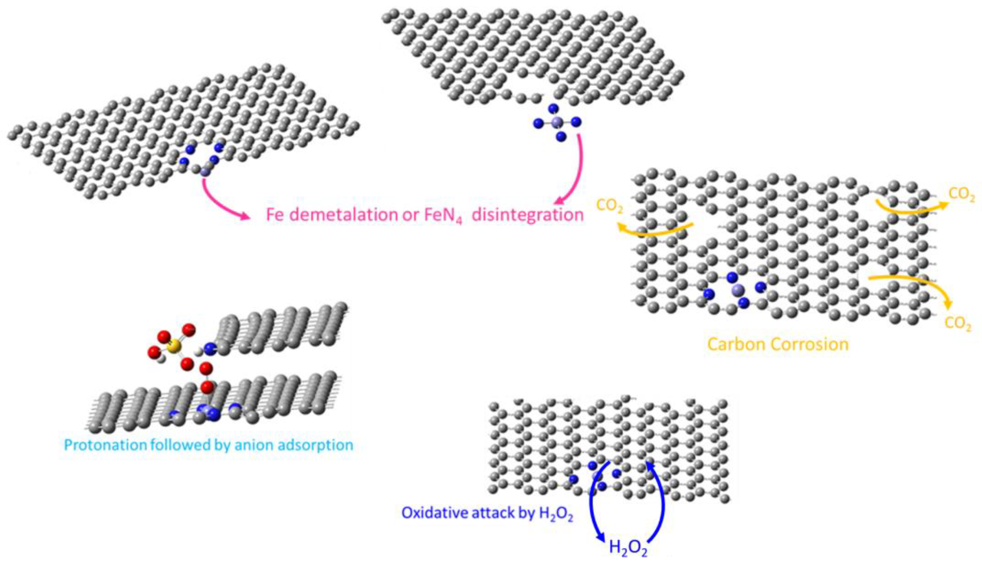
2.4. Degradation Mechanisms

While significant research exists on the degradation mechanisms of platinum catalysts supported on both carbon and non-carbon substrates [59,60], fewer studies have delved into the degradation processes specific to M–N–C catalysts. The subsequent section will provide a brief overview of the degradation mechanisms proposed in the literature for these catalysts (Figure 3).

2.4.1. Fe Dissolution or FeN4 Disintegration

Fe–N–C catalysts face degradation primarily through demetallation and disintegration of FeN4 active sites. Under acidic conditions typical of PEM fuel cells, iron (Fe) ions within FeN4 moieties undergo oxidation from Fe2+ to Fe3+ [62]. This oxidation process leads to a reduction in ion size and can cause Fe3+ to leave from its N4 coordination, resulting in a strained state [63]. This strained state can lead to detachment from the carbon matrix, a process known as demetallation, impairing catalytic efficiency [64,65]. Additionally, the disintegration of FeN4 active sites can occur due to chemical degradation, where the carbon matrix surrounding the FeN4 sites deteriorates over time. These mechanisms of Fe demetallation and FeN4 disintegration contribute to the gradual decline in catalytic activity and stability of Fe–N–C catalysts, posing significant challenges for their long-term performance and practical application.

2.4.2. Carbon Oxidation

Carbon oxidation is a significant degradation pathway for PGM-free catalysts, particularly those containing MN4 active sites used in fuel cells. Despite the kinetic hindrance, carbon is thermodynamically prone to oxidize to carbon dioxide (with a standard potential of 0.207 V) during fuel cell operation. Elevated temperatures and potentials accelerate this process [66], potentially leading to structural damage and decreased ORR activity of MN4 active sites [67]. Indeed, the oxidation of carbon surfaces directly affects their integrity and can indirectly compromise the stability of the catalytic sites [68,69]. Catalysts with a higher degree of graphitization exhibit improved resistance to corrosion, highlighting the importance of carbon structure in mitigating degradation pathways in these catalysts.

2.4.3. Oxidative Attack of Carbon Structure by H2O2

Fe–N–C catalysts undergo degradation primarily due to the generation of hydrogen peroxide (H2O2). This degradation mechanism begins with the incomplete reduction of oxygen at the cathode forming H2O2. Once formed, hydrogen peroxide can further decompose into highly reactive hydroxyl radicals (·OH) via Fenton-like reactions facilitated by the iron sites in the catalyst. These radicals are highly destructive, capable of attacking the carbon matrix, causing structural breakdown of the catalyst, loss of active sites, and overall decline in catalytic performance and durability [70]. This process underscores the critical challenge of improving catalyst stability to enhance the longevity and efficiency of PEM fuel cells. Acid leaching is a viable strategy to mitigate this issue by removing unstable and unreactive phases from the porous catalyst, often resulting in significantly improved ORR activity [71].

2.4.4. Anion Adsorption of the Active Site

Dodelet’s group identified the protonation followed by possible anion adsorption of the active site as a degradation mechanism affecting Fe–N–C catalysts [72]. This process involves the protonation of active sites, which can alter their electronic structure and chemical environment. Subsequent adsorption of anions can further impact the stability and reactivity of the catalyst, potentially leading to diminished performance in ORR. Consequently, the altered active sites become more susceptible to anion adsorption, particularly from species such as sulphate (SO₄2⁻) and phosphate (PO₄3⁻) present in the fuel cell environment. These anions can adsorb onto the protonated active sites, blocking them and thereby hindering the catalytic activity.

3. Electrode Structure and Mass Transport Properties

The activity targets with H2/O2 feed at 0.9 V, 80 °C, and 100% relative humidity (RH) of the U.S. Department of Energy (DOE) and the FCH 2 JU are 44 mA/cm2 (0.5 bar gauge/0.5 bar gauge) and 75 mA/cm2 (1 bar gauge/1 bar gauge), respectively [73]. Despite the many and important advances in achieving high intrinsic electrocatalytic activity, it is not the only parameter that determines the performance of the corresponding electrodes and MEAs. ORR is a surface reaction, and the three-phase boundary, as well as the dynamics of the electrochemical interface are crucial factors affecting both efficiency and stability. Catalyst sites are electrochemically active only when there is access and unhindered transport for electrons, protons, reactants (gas), and product water to and from them [74]. Contact between the catalyst and the electrolyte, as well as the microporous structure of the catalytic layer, become important properties that need careful optimization in order to maximize the extent of the electrochemical interface and therefore the catalyst utilization.
Proton-conductive ionomers, most commonly FPSA (perfluorosulfonic acid) type such as Nafion, are used inside the catalytic layer (CL) to enable mass transport of protons by connecting the active catalyst sites with the polymer electrolyte. Considerations for efficient performance include the proton conductivity of the ionomer, its homogeneous distribution throughout the catalytic layer, the catalyst–ionomer interface and the mass transport of oxygen through formed thin ionomer layers over the catalyst. The ionomer content must be carefully optimized to spread over the catalyst and increase the electrochemically active area, while at the same time its thickness should be low enough not to hinder the diffusion of the reactants. For conventional Pt/C electrodes, an optimal ionomer thickness of about 7 nm has been estimated [75].
The presence of water ensures and assists high proton conductivity for both the ionomer and the electrolyte. However, achieving the optimal amount of water that will not lead to excessive liquid water and electrode flooding is also challenging, and thus low-temperature PEM fuel cells suffer from inefficient water management. Flooding can be detrimental to the performance, as it creates ganglia that impede mass transfer processes and reduce the electrochemical surface area. Certain catalyst properties (e.g., hydrophobicity), overall pore structure, and ionomer type are responsible for water management. In fact, the microstructure of the CL, as defined by material properties (porosity, size, chemistry), spatial distribution, and agglomerations, controls all transport processes. In addition, dynamic operation and changes in the operation condition lead to restructuring of the electrochemical interface and thus add another challenge to parameter-tuning towards stable and efficient operation under a large operational window. Wang et al., schematically presented the types of mass transport resistances in an electrode and how these are affected by the presence of ionomer and water, as seen in Figure 4 [76]. The three main processes include molecular diffusion (pressure dependent), diffusion through smaller pores (Knudsen diffusion), and diffusion through solid-state (ionomer).
All the aforementioned issues have been explored for many years for Pt-based supported catalysts [77,78]. Although studies on PGM-free electrocatalysts are fewer, considerable attention to these critical parameters is rapidly growing, because they fundamentally determine performance and ex-situ studies do not accurately reflect behavior at the MEA level [57]. Compared to PGM-supported electrocatalysts, PGM-free materials have a substantially lower density of active sites, and lower specific activity or turnover frequency (TOF). An assessment made by Jaouen et al. [73] revealed that even for catalysts with TOFs similar to Pt, thick GDEs are inevitable due to low site density. Increasing the site density (e.g., Fe-site density > 3%) remains a significant challenge. Therefore, this overall lower volumetric activity of PGM-free catalysts leads to the need for high catalyst loadings of about 4 mg/cm2 [79]. As a consequence, the catalytic layer becomes very thick, even reaching an order of magnitude higher thickness (~100 μm) [73,80] compared to the typical ~10 μm CLs when conventional Pt/C is used [81]. Increased thickness can lead to inhomogeneities, increased resistances, and losses from transport issues of protons, gaseous reactants, and liquid water. Mass transport characteristics of PGM-free CLs were studied using experiments with different carrier gases to determine the mass transport coefficient for oxygen in the gas phase and non-gas phase [82]. It was thus demonstrated that the main limitations originate from the CL in the case of PGM-free catalysts, and resistance was higher when contrasted with conventional Pt-based electrodes, due to the thicker CL.
The reaction active sites are located on the surface, as well as hosted inside the micro-pores. The micro- and macrostructure of the CL, as well as other cell components, is critical for performance and stability, since they essentially determine all charge and mass transport properties and limitations and therefore corresponding losses (higher overpotential). The electrode/electrolyte configuration is symmetrical and multi-component. At each electrode, the CL, which incorporates both the catalyst and the ionomer binder, is deposited on a gas diffusion layer (GDL), such as carbon paper or cloth with a thickness of a few hundreds of micrometers, coated with a 50–70 μm hydrophobic microporous layer (MPL), commonly being a mixture of carbon particles and PTFE hydrophobic binder, serving for gas-distribution, water removal, and current collection [81]. The importance of the pore structure was evidenced by Shui et al., in whose research a nanofibrous structure led to the introduction of enough pores with size above 50 nm to promote mass transfer towards the densely placed sites, resulting overall in high volumetric activity [18]. Stariha et al., also studied the effect of the CL morphology and pore structure and found that pore connectivity plays the key role in transport properties affecting cell performance [83]. It becomes clear that losses originating from mass transport limitations vary with conditions, feed, and the thickness of the CL. An analysis made by Lopes et al., using PGM-free CLs revealed that the losses attributed to mass transport limitations account for ~100 mV at 1 A/cm2 [84]. To fine-tune the electrode properties, the strategy involves exploring different ionomers, catalyst loadings, catalyst-to-ionomer ratio, electrode preparation methods, and parameters for the MEA assembly.

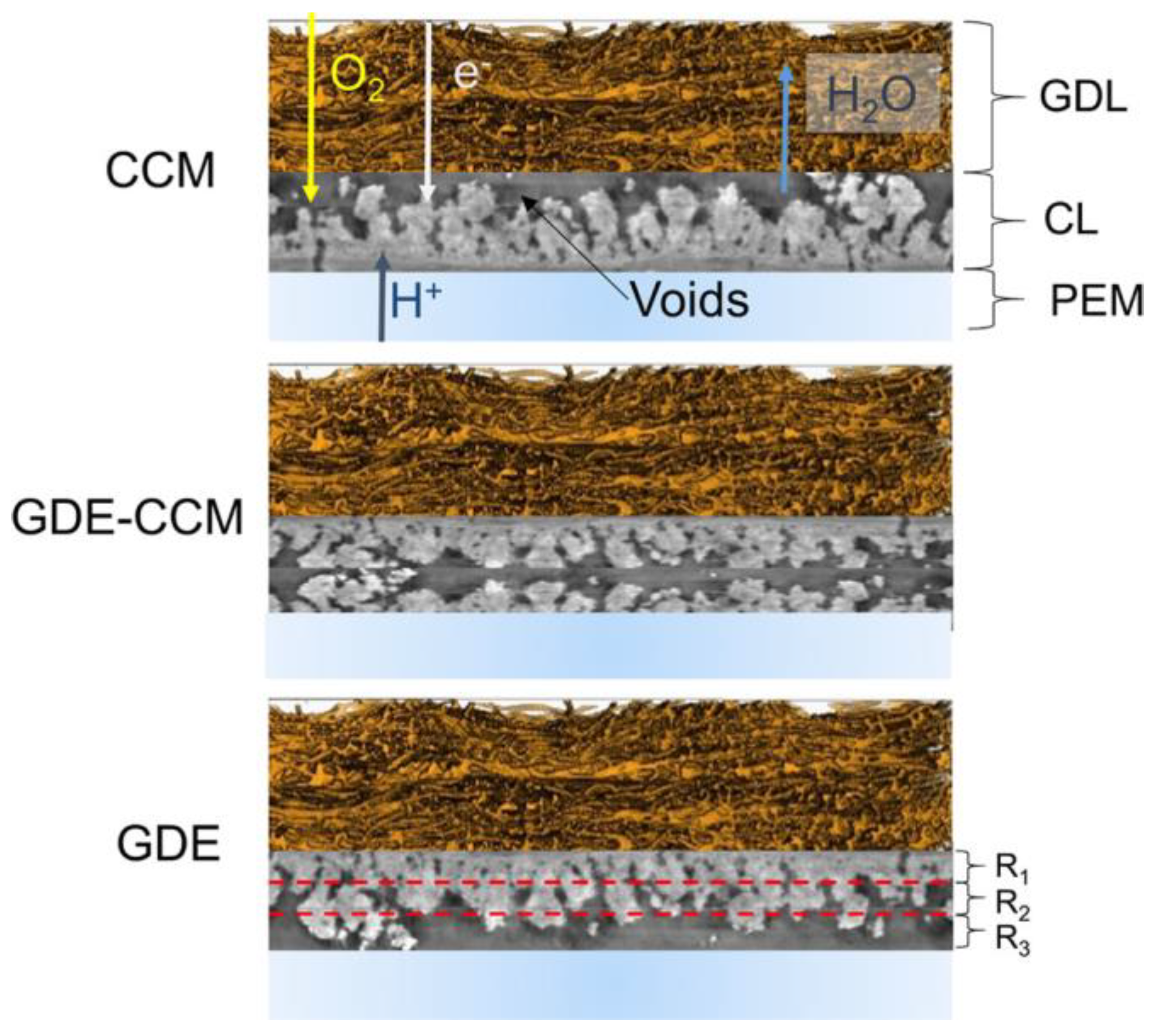
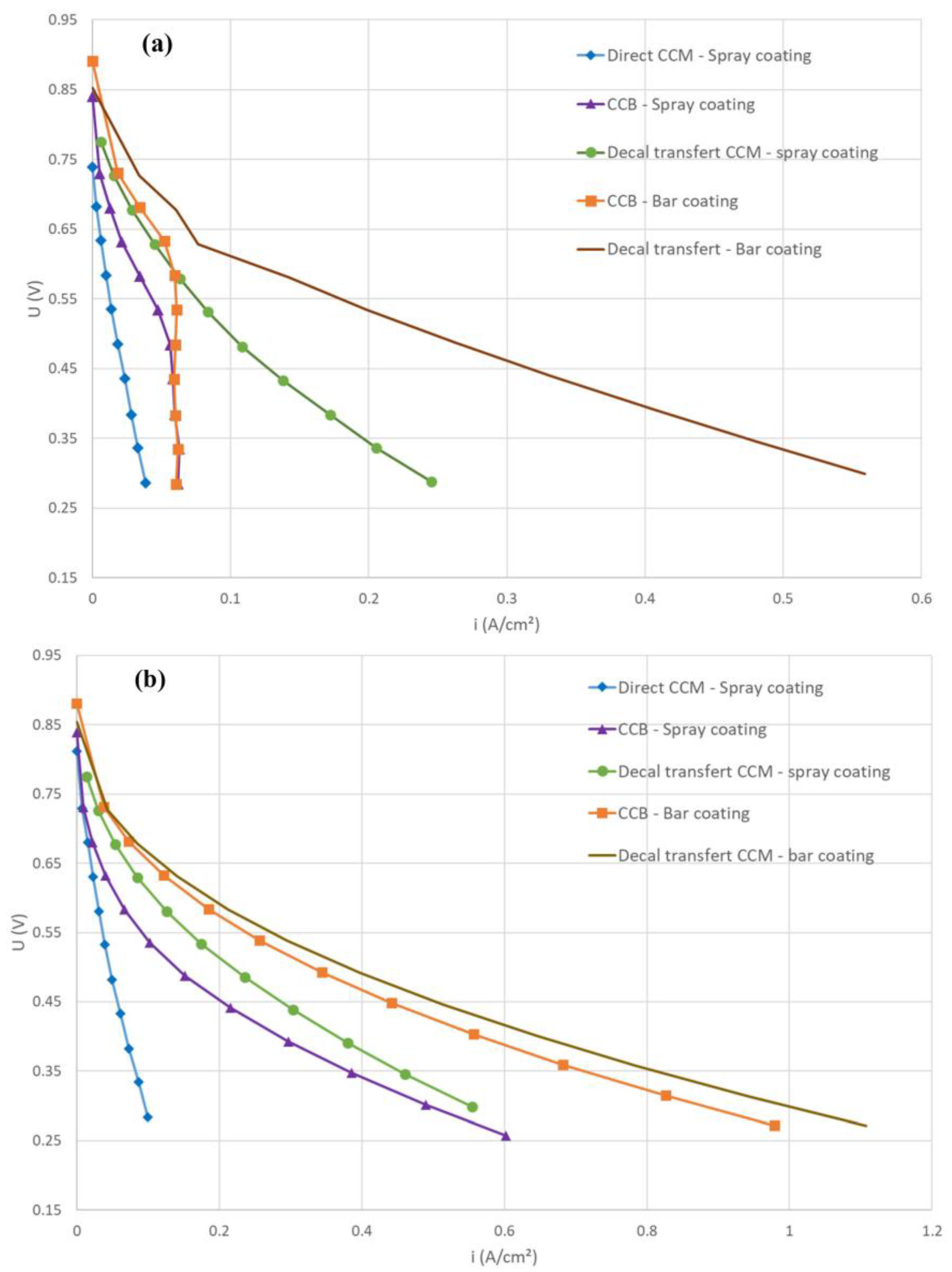
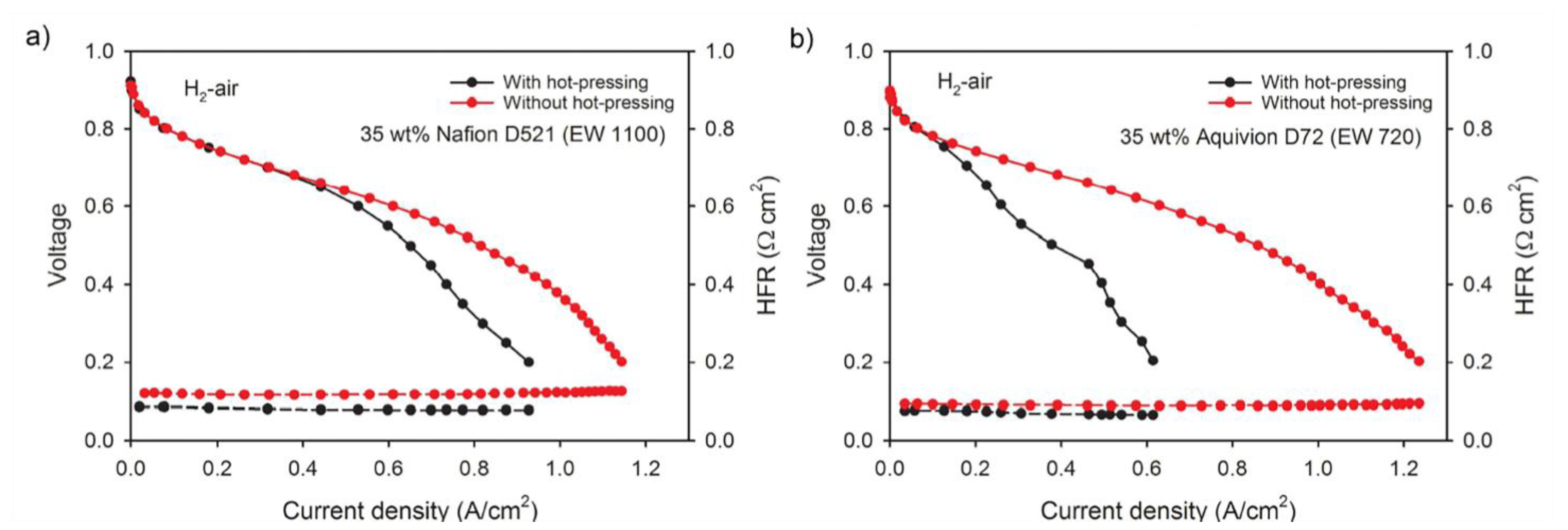
3.1. Membrane-Electrode Assembly (MEA) Fabrication

Despite the properties of the constituents (catalyst size and hydrophobicity, ionomer amount and type), the microstructure of the CL is influenced by the preparation method of the electrode/electrolyte configurations. The most common approaches are the catalyst-coated membrane (CCM), where the catalytic layer is deposited onto the polymer electrolyte directly or indirectly (decal method), and the membrane-electrode assembly (GDE–MEA), where gas-diffusion electrodes (GDE) are first being prepared by depositing the CL onto the GDL/MPL. The final step involves hot-pressing all the constituents to achieve the final complete configuration, namely GDEs with the electrolyte in between or GDL/MPLs with the CCMs.
Understanding the structure and mass transport properties of PGM-free electrodes, as well as how these correlate with performance, is critical for optimization. The morphology and pore structure of GDEs prepared with a Fe–N–C electrocatalyst (2-methylimidazole, glucoryl and streptomycin precursors, silica sacrificial template) were studied using nano- and micro-X-ray computed tomography (CT), with special attention on the water management as characterized and modeled [85]. The CL was deposited on the GDL/MPL by hand-spraying to reach a catalyst loading of 4 mg/cm2. The study concluded that the electrode structure was not uniform and that the part that was deposited last had larger voids and high tortuosity. Water management at the components’ interface thus became challenging and dependent on local capillary pressure.
In a later study, Liu et al., made a systematic comparison of three electrode fabrication methods, namely the CCM, the GDE–MEA, and a hybrid GDE–CCM (the double-layered cathode design), where the deposited catalyst was equally divided on the PEM electrolyte and the GDL/MPL, as shown in Figure 5 [80]. The N-doped carbonaceous catalyst with atomically dispersed iron (nicarbazin precursor, silica sacrificial template) was deposited by hand-spraying the ink incorporating 45 wt% Nafion ionomer followed by evaporative drying. As was proven, the catalytic layer had through-thickness inhomogeneities and interfacial regions, while large pores and surface roughness were formed at different parts of the CL depending on the fabrication method followed. Those regions were responsible for electrode flooding and low performance, as liquid water accumulated in the larger voids due to the catalyst’s hydrophobic nature, drawing water away from other parts of the layer such as small macro- and mesopores [86]. Depending on conditions and current density, the equilibrium between water management and ionic potential highlighted a different mode of cell preparation, while overall the GDE–CCM showed better behavior in most cases. Control over the evaporation process can, however, result in a more homogeneous layer, maximizing performance.
Toudret et al., investigated the effect of the CCM fabrication method on the CL and cell performance [87]. The CL was deposited on the polymer electrolyte directly (direct CCM), and on the GDL/MPL (CCB) or PTFE decal substrate (decal transfer CCM) using spray or bar coating. By keeping constant the catalyst loading (2 mg/cm2) and ionomer content (47 wt%), the CL had in all cases the same composition, and the thinner layer was translated into a denser and less porous structure. The fabrication procedure made a big difference in the thickness of the CL, which ranged from 18 μm (spray coating on the membrane) to 90 μm (bar coating on decal substrate). The double-layer capacitance and cell performance were seriously influenced by the fabrication process, with the decal transfer CCM showing the best performance, most probably due to increased porosity (Figure 6).
The role of compression and porosity was studied by Yin et al. [88]. The Fe–N–C catalyst (polyaniline and cyanamide as precursors and carbon support) was deposited by brush-painting onto the electrolyte, resulting in a catalyst loading of about 4.8 mg/cm2. One MEA was prepared by hot-pressing the GDL/MPL with the CCM (120 °C for 5 min, 5.3 MPa), and the other without hot-pressing the cathode. The latter CL was about 30–40 μm thicker, maintaining higher porosity. The polarization curves presented in Figure 7 revealed that the MEA that was hot-pressed, despite the lower high-frequency resistance, presented mass transport issues and notable performance losses at high current densities. The phenomenon was more severe when a lower EW ionomer was used, Figure 7b, pointing to the fact that this constitutes one more parameter to optimize.

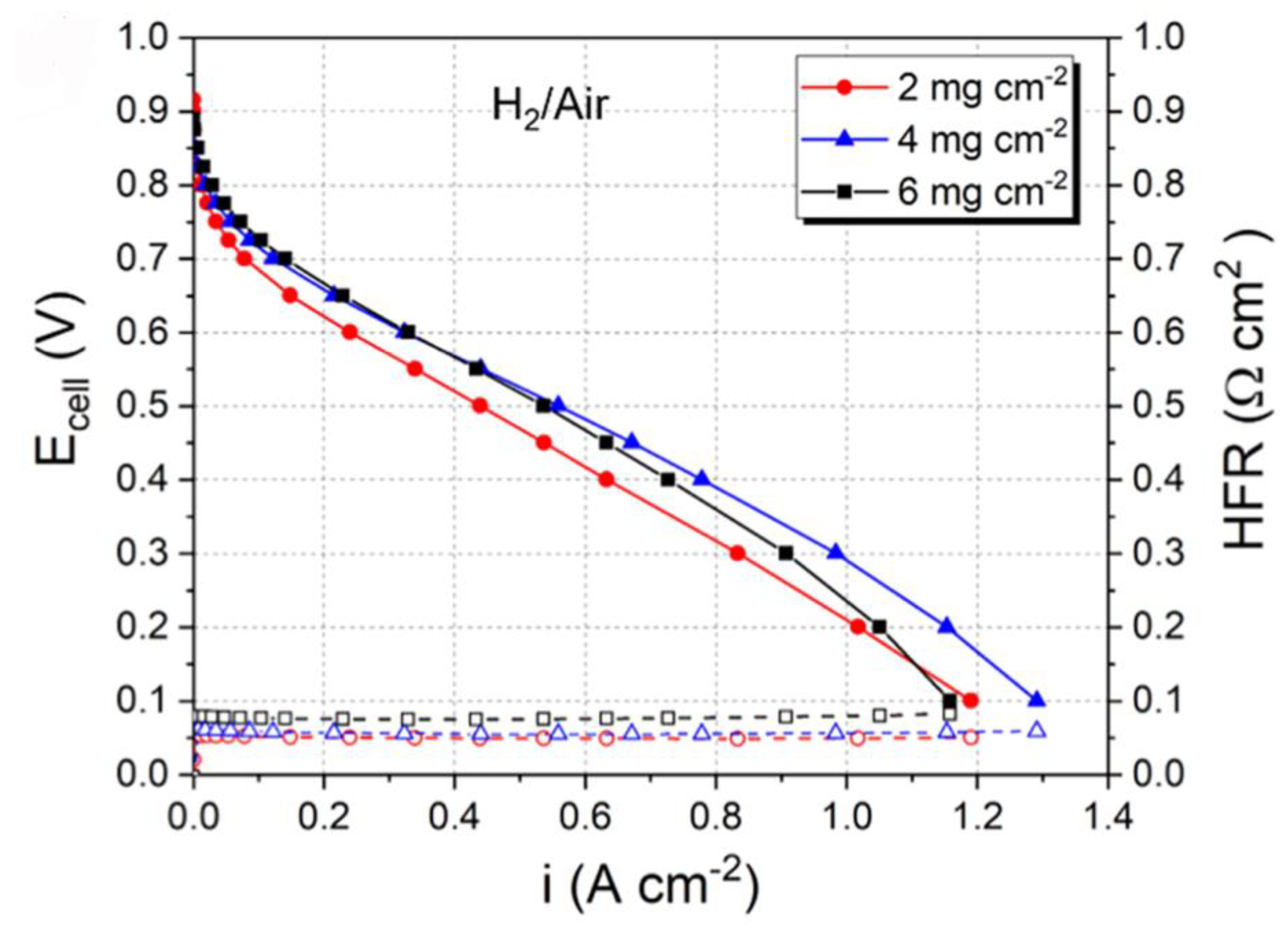
3.2. PGM-Free Catalyst Loading

The need for high catalyst loadings in the range of 3–5 mg/cm2 has been validated by Osmieri et al. [79]. Using commercial Fe–N–C catalyst (Pajarito Powder LLC, Albuquerque, NM, USA), the cathodic electrodes were prepared by paint-brushing the ink on the PEM, resulting in different catalyst loadings of 2, 4, and 6 mg/cm2, while keeping the Nafion content constant at 35 wt%, as seen in Figure 8. The lower loading resulted in decreased performance, while 6 mg/cm2 was not recommended, as mass transport limitations were introduced at the expense of cell performance at high current densities.
Baricci et al., analyzed the effect of catalyst loading using polarization curves and electrochemical impedance spectroscopy (EIS) at different current densities interpreted by modeling [89]. The Fe–N–C PGM-free catalyst (nicarbazin, 2-methylimidazole, imidazolidinyl urea, and carbendazim as nitrogen-precursors and silica sacrificial template) was deposited by spraying on the polymer electrolyte to reach loadings of 1 and 4 mg/cm2. As presented in the example of Figure 9a, increased loading led to improved performance at low overpotential values, whereas at higher current densities the slope became steeper. Impedance spectra (Figure 9b) revealed that high-frequency resistance and distortion in the imaginary part of the spectra increased with layer thickness, explained by increased CL electrical resistance, non-uniform ionic conductivity, and introduced limitations.

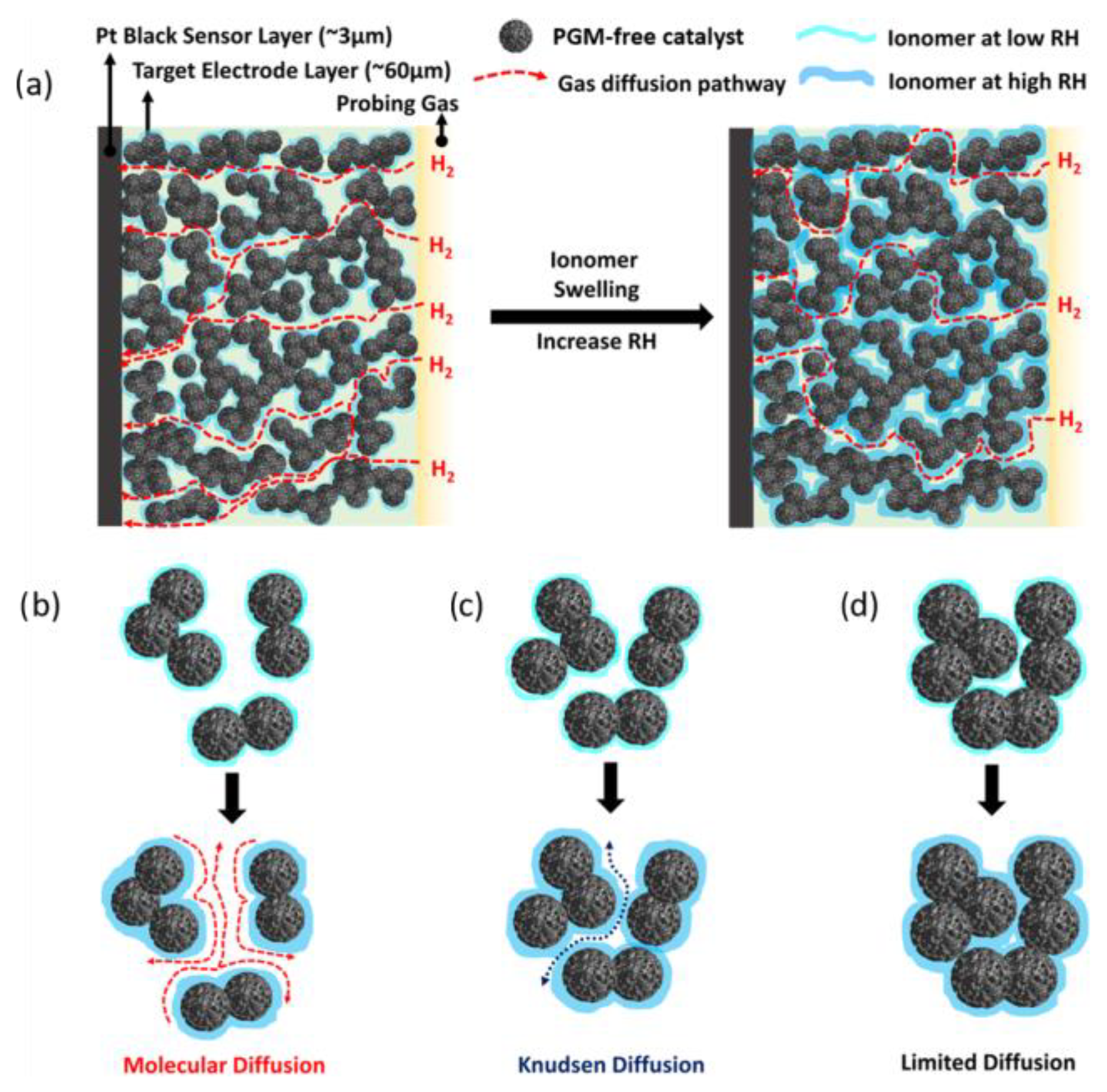
3.3. The Role of the Ionomer and Ink Composition

Nafion is commonly used as a binder in low-temperature GDEs, and its amount is a parameter that needs optimization. Unfortunately, there is no common practice, and for each electrocatalytic system, the ionomer-to-catalyst ratio needs to be carefully assessed. As previously mentioned, the extent of the electrochemical interface is dependent on the ionic pathways and proton conductivity from the active sites to the polymer electrolyte. While this could be interpreted as introduction of high ionomer amount in the CL, excess quantity leads to electrical isolation of catalyst particles, as well as blockage of active sites due to thick ionomer layer covering the reaction site and impeding oxygen mass transport. The fabrication of the CL involves the preparation of an ink by dispersing the catalyst and ionomer in a medium, most commonly a mixture of water and isopropanol or ethanol, subsequent deposition of the ink on the electrolyte, a decal substrate or the GDL/MPL, and finally drying for the evaporation of the solvents. It becomes apparent that the microstructure of the CL depends strongly on the formulated ink, subject to the catalyst properties (chemistry, size) and the composition parameters, i.e., constituents and percentage of solvents and solid materials.
K. Artyushkova et al., investigated the impact of varying ionomer contents on the performance of a pyrolyzed Co porphyrin catalyst at the cathodic electrode [90]. They maintained a constant catalyst loading of 4 mg/cm2, while using different amounts of Nafion, specifically 0.5, 1, 2, and 3 times the weight of the catalyst. The 1:1 weight ratio (Nafion content: 50 wt%) revealed optimal performance and stability, while higher ionomer content resulted in both its oxidation and leaching of Co in the form of oxides. In another work, GDEs with 25, 35, and 45 wt% Nafion were prepared using Fe–N–C catalysts (nicarbazin precursor, silica sacrificial template), while carbon additives were further added to improve electronic conductivity while increasing the ionomer amount [91]. In these configurations, although the ionomer is important for the kinetic regime, the 35 wt% content gave the best performance, and the use of additives was not beneficial. However, increase of the Nafion amount and thus the use of carbon materials was proposed for achieving high energy efficiency.
Uddin et al., also studied the integration of the ionomer (Nafion) and corresponding transport losses at cathodes incorporating a MOF-derived Fe–N–C catalyst [92]. A manual doctor blade was used for preparing the GDEs with a loading of 4 mg/cm2. The catalyst preparation methodology allowed tuning its particle size, and it was thus revealed that an interplay exists. The size influences the spatial distribution of the ionomer and affects the performance (Figure 10a). Moreover, for a specific size, Nafion content must be optimized, as presented by the polarization curves of Figure 10b. After optimization of the specific catalyst under study, the authors achieved 0.41 W/cm2 at 0.67 V and a degradation rate of 1 mA/cm2/h at 0.7 V.
In another work, a hierarchical porous Fe–N–C catalyst (aniline and cyanimide as nitrogen-precursors) was studied [93]. The GDEs were prepared by brushing to reach a catalyst loading of 4 mg/cm2 with three different Nafion contents, namely 35, 50, and 60 wt%. GDEs with high ionomer contents showed enhanced performance at >0.7 V, reflecting an improved interface and increased catalyst utilization. At higher current densities, the 35 wt% Nafion content was superior due to the more efficient water removal and mass transport properties. At 0.8 V, a current density of about 75 mA/cm2 was presented at 80 °C and 100% RH with air feed.
Komini Babu et al., used nano-CT and corresponding simulations to resolve the spatial distribution of the ionomer and pore structure [94]. CCMs with a cathode CL of 100 μm were fabricated by direct deposition on the electrolyte to obtain a catalyst loading of 4 mg/cm2 and Nafion contents of 35, 50, and 60 wt%. The cyanamide polyaniline–iron catalyst used had particle sizes of 1−10 μm, leading to beneficial porous electrode structure. The performance changes observed in Figure 11a were attributed to differentiations in the distribution of Nafion and resulting morphology (Figure 11b). A more uniform distribution was achieved for 50 wt% ionomer. Nafion agglomerates were observed outside the catalyst particles in the case of 35 wt% Nafion, while thick Nafion layers were formed at 60 wt%. Thus, the low amount of Nafion led to poor coverage of catalyst particles and lower performance. On the other hand, increased Nafion content led to severe flooding as the ionomer built up causing ionic limitations (Figure 11a).
Malco et al., also highlighted the importance of an optimized ionomer content [95]. To understand the behavior of PGM-free catalysts and the role of the ionomer, the authors proposed a combinatorial strategy through polarization curves and electrochemical impedance spectroscopy (EIS). Three types of pyrolyzed transition M–N–C catalysts were used, and electrodes with varying ionomer content were fabricated by ink deposition (in isopropanol) on GDL/MPL. In the presence and absence of reactant at the cathode (no Faradaic reaction), inhomogeneous ionomer coverage and therefore resistance in the CL could be identified by deviations in the Nyquist plots, making EIS a diagnostic tool for electrode optimization.
A high throughput method was proposed by Osmieri et al., where a study of the effect of fabrication parameters on the performance of PGM-free electrodes was realized using a segmented cell [96]. The cathodic CLs were prepared by depositing inks of Fe–N–C catalysts onto GDL/MPL using a motorized coater (loading of about 3 mg/cm2). Among others, the parameters under study were the ionomer content ranging between 15 and 45 wt%, the water/isopropanol ratio in the ink (50 and 82 wt% water), and the drying temperature (60–90 °C) towards the formation of the CL. The study indicated a clear trend of improvement in performance with the ionomer amount, thus revealing the superior performance of the higher Nafion content under both air and oxygen cathode feed. Interestingly, the drying temperature showed no clear effect, while the higher ratio of water to isopropanol in the ink made a significant difference to the obtained performance under different operating conditions, reaching almost twice the current density values when the water content of the ink increased from 50 to 82 wt%.
At the same pace, the effect of water in the ink and the interplay of gas-phase transport and proton conductivity in the CL were studied using both characterization techniques (scanning transmission electron microscopy/energy dispersive spectroscopy and nano-scale resolution X-ray computed tomography) and electrochemical evaluation of the cell performance under several values of RH at the cathode [97]. This study utilized a commercial PGM-free catalyst (Pajarito Powder, LLC), and the CL was deposited by paint-brushing inks in water/isopropanol medium on the membrane, resulting in a catalyst loading of about 4 mg/cm2 with 35 wt% Nafion content. The 82 wt% water content in the ink resulted in electrodes with 50% higher performance at high current densities and air feed and 100% RH compared to 0 wt% water, attributed to the larger pores and better mass transport in the gas-phase (Figure 12a). Conversely, at lower RH, the robustness and improved ionic pathways of the electrode from the ink with 50 wt% water were favorable (Figure 12b). When no water was used, the interactions between ionomer and catalyst were limited, and, although ionic conductivity was satisfactory, the gas-phase mass transport resistance was maximized (Figure 12c,d). For optimum performance, the balance of the two resistances (mass transport and ionic) must be reached.
In the same line, using a combination of the H2 pump method and a sensor layer, the bulk electrode mass transport resistance was evaluated for PGM-free CLs with commercial Fe–N–C catalyst (Pajarito Powder, LLC) and different Nafion contents in the range of 15–45 wt% [76]. Through EIS, proton conductivity was also measured for the different MEAs, and these CL properties were plotted at several RH values (Figure 13). It was thus evidenced that the cell performance was a trade-off between these two limiting factors, and that a balanced approach is necessary.
In order to tune the microstructure of the CL, it is important to understand the interparticle interactions, particle agglomeration, and the interactions between ionomer and catalyst particles at the ink level, and how these are influenced by the ionomer-to-catalyst ratio, the concentration of solids, and the solvent composition in the ink. Khandavalli et al., reported that agglomeration was increased for inks with catalyst concentration ≥2 wt% due to the hydrophobicity of the catalyst [98]. Maximum ink stability was achieved for an ionomer-to-catalyst ratio of 0.35, while for higher Nafion percentages, the amount of water in the ink determined the ionomer–catalyst interactions and thus necessitates careful tuning.
Following the established findings that high catalyst loadings are necessary but provoke mass transport limitations, and that the ionomer content is a critical parameter, Banham et al., rationally designed the CL to achieve maximum performance [99]. GDEs were prepared with a pre-commercial catalyst (Nisshinbo Holding, Tokyo, Japan) with loadings of 1, 2.5, and 4 mg/cm2 and 40 wt% ionomer (EW 700). As expected, the higher loading and thus electrode thickness introduced mass transport issues that eventually decreased performance. To overcome this behavior, increased porosity to facilitate O2 transport was achieved by decreasing the ionomer content to 35 wt%, making sure that proton conductivity did not became a limitation [100]. A peak power of 570 mW/cm2 under air was achieved, stressing the importance of a combinatorial approach towards optimization.

3.4. Operating Fuel Cell Conditions

Despite the electrode and MEA fabrication parameters, fuel cell operating conditions that can influence the performance have been researched. In the previous sections, the effect of current density and potential have been mentioned in relation with the different electrode composition. Regarding the fuel cell testing parameters, the effect of the feed flow rate was evaluated [79]. Measurements were conducted with a commercial Fe–N–C catalyst at 80 °C, 100% RH, and 150 kPa, examining the impact of varying gas flow rates on the anode and cathode of a MEA. Tests were performed by altering the gas flow rate on one electrode while keeping the other constant. Results showed that changing the anode flow rate from 300 to 2000 scm3/min did not significantly affect performance in either H2/air or H2/O2 conditions, indicating that anode flow rate above 300 scm3/min is not limiting. However, varying the cathode flow rate from 300 to 3300 scm3/min significantly impacted the H2/air polarization curves at high current densities (above 0.6 A/cm2), demonstrating the importance of optimal air flow rates. In contrast, the H2/O2 performance remained unaffected by cathode flow variations due to high stoichiometry and enhanced mass transport with pure O2. These findings suggest that for H2/air tests, higher cathode flow rates are beneficial at high current densities.
Moreover, the effect of RH (0–100%) was investigated in the work of Toudret et al., where the authors used a commercial Fe–N–C catalyst layer and investigated the ionomer swelling behavior during the fuel cell operation through operando small-angle X-ray scattering (SAXS) measurements [101]. SAXS measurements were conducted on two MEAs at OCV under N2 flow, with rates of 6 Nl/h for the Pt/C-based MEA and 10 Nl/h for the non-noble MEA. High flow rates ensured gas passage through the cathode compartment and maintained consistent relative humidity (RH) across the MEA. Operando measurements were not feasible for the non-noble MEA due to insufficient current generation. The peak position shifted with RH, reflecting water uptake and swelling. The non-noble catalyst layer’s ionomer peak suggested large ionomer aggregates, indicating poor dispersion.
In another work, a PANI-based Fe–N–C catalyst was employed as the cathode electrode with a scalable synthesis process [102]. The catalyst was tested in a pre-industry-size (50 cm2) fuel cell to evaluate its performance under various conditions, including temperature, pressure, humidity, and oxygen concentration. The study on the aforementioned fuel cell testing parameters yielded several key conclusions. Firstly, the variation of operating temperature (60–80 °C) revealed that higher operating temperatures enhance fuel cell performance by improving proton conductivity and reducing ohmic losses at high current densities. However, the open cell voltage decreased with increasing temperature due to thermodynamic effects. Secondly, the variation of operating pressure (0.5–1.5 bar) led to the conclusion that increased operating pressure improves performance in both kinetic and ohmic regions, as cell voltage positively correlates with gas pressure. Regarding relative humidity (RH: 60–120%), maintaining proper hydration levels is crucial. Low RH conditions impair proton transport due to shrinking water channels, while excessively high RH can lead to water condensation and flooding. Optimal performance was observed at higher RH levels without flooding, even at 120% RH. Lastly, oxygen concentration (10.5 and 21%) significantly impacts performance. Higher oxygen levels resulted in better performance, while lower concentrations led to increased voltage losses in both kinetic and ohmic regions. This underscores the importance of maintaining adequate oxygen levels for optimal fuel cell operation.

4. Remarks

Significant efforts have been made over the years to develop PGM-free materials with high electrocatalytic activity and adequate stability. This review highlights important aspects and approaches, indicating the current status and lessons learned. Catalysts are still at an early stage of development, with many different classes of materials being explored. Consequently, their incorporation into fuel cell cathodes, which requires extensive optimization, may currently seem less impactful. However, understanding the properties that make a difference in situ is crucial when designing a catalyst. Numerous variables related to electrode specifications have significant impact. Unfortunately, few studies have applied these materials to fuel cells, and even fewer focus on optimization by studying the effect of each variable to extract mechanistic insights. The preparation method and structure of catalyst layers (CLs) in PEMFCs significantly impact their performance. Electrode fabrication methods include the catalyst-coated membrane (CCM) and the gas-diffusion-electrode–membrane-electrode assembly (GDE–MEA), each influencing the microstructure and performance of the catalyst layer. Methods like direct deposition, decal transfer, and hybrid GDE–CCM show varied effects on uniformity, porosity, and thickness of the CL. Optimizing the morphology and pore structure of the CL is crucial for enhancing water management and performance. The distribution and size of pores significantly affect water management and electrode performance. Non-uniform structures can lead to issues like electrode flooding and poor water removal. Regarding the catalyst loading, higher catalyst loadings (4–5 mg/cm2) generally improve the performance at low current densities but can introduce mass transport limitations at higher current densities. Optimal performance requires balancing catalyst loading to avoid excessive thickness and related mass transport issues. The amount and distribution of ionomer within the CL also play a pivotal role. Excessive ionomer can isolate catalyst particles and block active sites, while insufficient ionomer reduces proton conductivity. Studies indicate that an ionomer content around 35–40 wt% generally yields the best performance in most cases, with specific ratios needing optimization based on the catalyst and fabrication method used. Thus, parameters such as ink formulation, solvent composition, and drying conditions significantly influence the microstructure and, consequently, the performance of the CL. Adjustments in the water-to-isopropanol ratio in the ink, drying temperatures, and control over the evaporation process can lead to better-performing and more homogeneous CLs. Overall, special attention should be given to efficient design of electrode fabrication techniques (including catalyst ink formulation), the deposition method, and the MEA assembly (conditions, pressing, etc.) to achieve effective interface, catalyst accessibility, and transport properties. These factors are decisive for practical applications in PEMFCs. However, considering all these variables makes the number of necessary tests exhaustive. Therefore, for each catalyst, a parallel optimization of parameters with the employment of diagnostics and simulation tools should be applied to develop protocols that save time and limit the number of trials.

Author Contributions

I.M.: investigation, writing—original draft, writing—review and editing; M.K.D.: investigation, writing—original draft, writing—review and editing. All authors have read and agreed to the published version of the manuscript.

Funding

This research received no external funding.

Conflicts of Interest

The authors declare no conflicts of interest.

References

  1. Wang, Y.; Pang, Y.; Xu, H.; Martinez, A.; Chen, K.S. PEM Fuel Cell and Electrolysis Cell Technologies and Hydrogen Infrastructure Development—A Review. Energy Environ. Sci. 2022, 15, 2288–2328. [Google Scholar] [CrossRef]
  2. Zhong, L.; Li, S. Unconventional Oxygen Reduction Reaction Mechanism and Scaling Relation on Single-Atom Catalysts. ACS Catal. 2020, 10, 4313–4318. [Google Scholar] [CrossRef]
  3. Mo, S.; Du, L.; Huang, Z.; Chen, J.; Zhou, Y.; Wu, P.; Meng, L.; Wang, N.; Xing, L.; Zhao, M.; et al. Recent Advances on PEM Fuel Cells: From Key Materials to Membrane Electrode Assembly. Electrochem. Energy Rev. 2023, 6, 28. [Google Scholar] [CrossRef]
  4. Wan, X.; Liu, X.; Li, Y.; Yu, R.; Zheng, L.; Yan, W.; Wang, H.; Xu, M.; Shui, J. Fe–N–C Electrocatalyst with Dense Active Sites and Efficient Mass Transport for High-Performance Proton Exchange Membrane Fuel Cells. Nat. Catal. 2019, 2, 259–268. [Google Scholar] [CrossRef]
  5. Zhang, H.; Hwang, S.; Wang, M.; Feng, Z.; Karakalos, S.; Luo, L.; Qiao, Z.; Xie, X.; Wang, C.; Su, D.; et al. Single Atomic Iron Catalysts for Oxygen Reduction in Acidic Media: Particle Size Control and Thermal Activation. J. Am. Chem. Soc. 2017, 139, 14143–14149. [Google Scholar] [CrossRef]
  6. Li, J.; Zhang, H.; Samarakoon, W.; Shan, W.; Cullen, D.A.; Karakalos, S.; Chen, M.; Gu, D.; More, K.L.; Wang, G.; et al. Thermally Driven Structure and Performance Evolution of Atomically Dispersed FeN 4 Sites for Oxygen Reduction. Angew. Chem. 2019, 131, 19147–19156. [Google Scholar] [CrossRef]
  7. Wu, Y.; Yuan, M.; Li, X.; Ding, R.; Duan, X.; Li, J.; Wang, Y.; Li, X.; Zhang, Y.; Liu, J. Assistance of Rearrangement of Active Sites in Fe/N/C Catalyst for Harvesting Ultra-High Power Density PEMFCs. Appl. Catal. B 2022, 312, 121365. [Google Scholar] [CrossRef]
  8. Wang, W.; Jia, Q.; Mukerjee, S.; Chen, S. Recent Insights into the Oxygen-Reduction Electrocatalysis of Fe/N/C Materials. ACS Catal. 2019, 9, 10126–10141. [Google Scholar] [CrossRef]
  9. He, Y.; Wu, G. PGM-Free Oxygen-Reduction Catalyst Development for Proton-Exchange Membrane Fuel Cells: Challenges, Solutions, and Promises. Acc. Mater. Res. 2022, 3, 224–236. [Google Scholar] [CrossRef]
  10. Miao, Z.; Li, S.; Priest, C.; Wang, T.; Wu, G.; Li, Q. Effective Approaches for Designing Stable M–N x /C Oxygen-Reduction Catalysts for Proton-Exchange-Membrane Fuel Cells. Adv. Mater. 2022, 34, e2200595. [Google Scholar] [CrossRef]
  11. Kumar, K.; Dubau, L.; Jaouen, F.; Maillard, F. Review on the Degradation Mechanisms of Metal-N-C Catalysts for the Oxygen Reduction Reaction in Acid Electrolyte: Current Understanding and Mitigation Approaches. Chem. Rev. 2023, 123, 9265–9326. [Google Scholar] [CrossRef]
  12. Zagal, J.H.; Bedioui, F.; Dodelet, J.-P. (Eds.) N4-Macrocyclic Metal Complexes; Springer New York: New York, NY, USA, 2006. [Google Scholar] [CrossRef]
  13. Jasinski, R. A New Fuel Cell Cathode Catalyst. Nature 1964, 201, 1212–1213. [Google Scholar] [CrossRef]
  14. Jahnke, H.; Schönborn, M.; Zimmermann, G. Organic Dyestuffs as Catalysts for Fuel Cells. In Physical and Chemical Applications of Dyestuffs; Springer: Berlin/Heidelberg, Germany, 1976; pp. 133–181. [Google Scholar] [CrossRef]
  15. Gupta, S.; Tryk, D.; Bae, I.; Aldred, W.; Yeager, E. Heat-Treated Polyacrylonitrile-Based Catalysts for Oxygen Electroreduction. J. Appl. Electrochem. 1989, 19, 19–27. [Google Scholar] [CrossRef]
  16. Proietti, E.; Jaouen, F.; Lefèvre, M.; Larouche, N.; Tian, J.; Herranz, J.; Dodelet, J.-P. Iron-Based Cathode Catalyst with Enhanced Power Density in Polymer Electrolyte Membrane Fuel Cells. Nat. Commun. 2011, 2, 416. [Google Scholar] [CrossRef]
  17. Wu, G.; More, K.L.; Johnston, C.M.; Zelenay, P. High-Performance Electrocatalysts for Oxygen Reduction Derived from Polyaniline, Iron, and Cobalt. Science 2011, 332, 443–447. [Google Scholar] [CrossRef]
  18. Shui, J.; Chen, C.; Grabstanowicz, L.; Zhao, D.; Liu, D.-J. Highly Efficient Nonprecious Metal Catalyst Prepared with Metal–Organic Framework in a Continuous Carbon Nanofibrous Network. Proc. Natl. Acad. Sci. USA 2015, 112, 10629–10634. [Google Scholar] [CrossRef]
  19. Li, Y.; Zhang, P.; Wan, L.; Zheng, Y.; Qu, X.; Zhang, H.; Wang, Y.; Zaghib, K.; Yuan, J.; Sun, S.; et al. A General Carboxylate-Assisted Approach to Boost the ORR Performance of ZIF-Derived Fe/N/C Catalysts for Proton Exchange Membrane Fuel Cells. Adv. Funct. Mater. 2021, 31, 202009645. [Google Scholar] [CrossRef]
  20. Liu, S.; Li, C.; Zachman, M.J.; Zeng, Y.; Yu, H.; Li, B.; Wang, M.; Braaten, J.; Liu, J.; Meyer, H.M.; et al. Atomically Dispersed Iron Sites with a Nitrogen–Carbon Coating as Highly Active and Durable Oxygen Reduction Catalysts for Fuel Cells. Nat. Energy 2022, 7, 652–663. [Google Scholar] [CrossRef]
  21. Lu, X.; Li, Y.; Yang, P.; Wan, Y.; Wang, D.; Xu, H.; Liu, L.; Xiao, L.; Li, R.; Wang, G.; et al. Atomically Dispersed Fe-N-C Catalyst with Densely Exposed Fe-N4 Active Sites for Enhanced Oxygen Reduction Reaction. Chem. Eng. J. 2024, 485, 149529. [Google Scholar] [CrossRef]
  22. Cui, J.; Chen, Q.; Li, X.; Zhang, S. Recent Advances in Non-Precious Metal Electrocatalysts for Oxygen Reduction in Acidic Media and PEMFCs: An Activity, Stability and Mechanism Study. Green. Chem. 2021, 23, 6898–6925. [Google Scholar] [CrossRef]
  23. Ćirić-Marjanović, G. Recent Advances in Polyaniline Research: Polymerization Mechanisms, Structural Aspects, Properties and Applications. Synth. Met. 2013, 177, 1–47. [Google Scholar] [CrossRef]
  24. Bashyam, R.; Zelenay, P. A Class of Non-Precious Metal Composite Catalysts for Fuel Cells. Nature 2006, 443, 63–66. [Google Scholar] [CrossRef]
  25. Wu, G.; Chen, Z.; Artyushkova, K.; Garzon, F.H.; Zelenay, P. Polyaniline-Derived Non-Precious Catalyst for the Polymer Electrolyte Fuel Cell Cathode. ECS Trans. 2008, 16, 159–170. [Google Scholar] [CrossRef]
  26. Zhang, N.; Zhou, T.; Chen, M.; Feng, H.; Yuan, R.; Zhong, C.; Yan, W.; Tian, Y.; Wu, X.; Chu, W.; et al. High-Purity Pyrrole-Type FeN 4 Sites as a Superior Oxygen Reduction Electrocatalyst. Energy Environ. Sci. 2020, 13, 111–118. [Google Scholar] [CrossRef]
  27. Wu, G.; Nie, Y. N, S Codoped Iron-Carbon-Based Electrocatalyst for Oxygen Reduction Reaction via Salt Recrystallization Strategy. Chem. Lett. 2021, 50, 124–127. [Google Scholar] [CrossRef]
  28. Kramm, U.I.; Herrmann-Geppert, I.; Behrends, J.; Lips, K.; Fiechter, S.; Bogdanoff, P. On an Easy Way to Prepare Metal–Nitrogen Doped Carbon with Exclusive Presence of MeN 4-Type Sites Active for the ORR. J. Am. Chem. Soc. 2016, 138, 635–640. [Google Scholar] [CrossRef]
  29. Ding, W.; Li, L.; Xiong, K.; Wang, Y.; Li, W.; Nie, Y.; Chen, S.; Qi, X.; Wei, Z. Shape Fixing via Salt Recrystallization: A Morphology-Controlled Approach to Convert Nanostructured Polymer to Carbon Nanomaterial as a Highly Active Catalyst for Oxygen Reduction Reaction. J. Am. Chem. Soc. 2015, 137, 5414–5420. [Google Scholar] [CrossRef]
  30. Zamani, P.; Higgins, D.; Hassan, F.; Jiang, G.; Wu, J.; Abureden, S.; Chen, Z. Electrospun Iron–Polyaniline–Polyacrylonitrile Derived Nanofibers as Non–Precious Oxygen Reduction Reaction Catalysts for PEM Fuel Cells. Electrochim. Acta 2014, 139, 111–116. [Google Scholar] [CrossRef]
  31. Fu, X.; Zamani, P.; Choi, J.; Hassan, F.M.; Jiang, G.; Higgins, D.C.; Zhang, Y.; Hoque, M.A.; Chen, Z. In Situ Polymer Graphenization Ingrained with Nanoporosity in a Nitrogenous Electrocatalyst Boosting the Performance of Polymer-Electrolyte-Membrane Fuel Cells. Adv. Mater. 2017, 29, 1604456. [Google Scholar] [CrossRef]
  32. Serov, A.; Workman, M.J.; Artyushkova, K.; Atanassov, P.; McCool, G.; McKinney, S.; Romero, H.; Halevi, B.; Stephenson, T. Highly Stable Precious Metal-Free Cathode Catalyst for Fuel Cell Application. J. Power Sources 2016, 327, 557–564. [Google Scholar] [CrossRef]
  33. Serov, A.; Artyushkova, K.; Atanassov, P. Fe-N-C Oxygen Reduction Fuel Cell Catalyst Derived from Carbendazim: Synthesis, Structure, and Reactivity. Adv. Energy Mater. 2014, 4. [Google Scholar] [CrossRef]
  34. Wu, R.; Song, Y.; Huang, X.; Chen, S.; Ibraheem, S.; Deng, J.; Li, J.; Qi, X.; Wei, Z. High-density active sites porous Fe/N/C electrocatalyst boosting the performance of proton exchange membrane fuel cells. J. Power Sources 2018, 401, 287–295. [Google Scholar] [CrossRef]
  35. Mun, Y.; Lee, S.; Kim, K.; Kim, S.; Lee, S.; Han, J.W.; Lee, J. Versatile Strategy for Tuning ORR Activity of a Single Fe-N 4 Site by Controlling Electron-Withdrawing/Donating Properties of a Carbon Plane. J. Am. Chem. Soc. 2019, 141, 6254–6262. [Google Scholar] [CrossRef]
  36. He, Y.; Liu, S.; Priest, C.; Shi, Q.; Wu, G. Atomically Dispersed Metal–Nitrogen–Carbon Catalysts for Fuel Cells: Advances in Catalyst Design, Electrode Performance, and Durability Improvement. Chem. Soc. Rev. 2020, 49, 3484–3524. [Google Scholar] [CrossRef]
  37. Wang, X.; Jia, Y.; Mao, X.; Liu, D.; He, W.; Li, J.; Liu, J.; Yan, X.; Chen, J.; Song, L.; et al. Edge-Rich Fe−N 4 Active Sites in Defective Carbon for Oxygen Reduction Catalysis. Adv. Mater. 2020, 32, 202000966. [Google Scholar] [CrossRef]
  38. Wang, X.; Zhang, H.; Lin, H.; Gupta, S.; Wang, C.; Tao, Z.; Fu, H.; Wang, T.; Zheng, J.; Wu, G.; et al. Directly Converting Fe-Doped Metal–Organic Frameworks into Highly Active and Stable Fe-N-C Catalysts for Oxygen Reduction in Acid. Nano Energy 2016, 25, 110–119. [Google Scholar] [CrossRef]
  39. Wang, G.; Deng, J.; Yan, T.; Zhang, J.; Shi, L.; Zhang, D. Turning on Electrocatalytic Oxygen Reduction by Creating Robust Fe–N x Species in Hollow Carbon Frameworks via in Situ Growth of Fe Doped ZIFs on g-C 3 N 4. Nanoscale 2020, 12, 5601–5611. [Google Scholar] [CrossRef]
  40. Li, Y.; Liu, X.; Zheng, L.; Shang, J.; Wan, X.; Hu, R.; Guo, X.; Hong, S.; Shui, J. Preparation of Fe–N–C Catalysts with FeN x (x = 1, 3, 4) Active Sites and Comparison of Their Activities for the Oxygen Reduction Reaction and Performances in Proton Exchange Membrane Fuel Cells. J. Mater. Chem. A Mater. 2019, 7, 26147–26153. [Google Scholar] [CrossRef]
  41. Mehmood, A.; Gong, M.; Jaouen, F.; Roy, A.; Zitolo, A.; Khan, A.; Sougrati, M.-T.; Primbs, M.; Bonastre, A.M.; Fongalland, D.; et al. High Loading of Single Atomic Iron Sites in Fe–NC Oxygen Reduction Catalysts for Proton Exchange Membrane Fuel Cells. Nat. Catal. 2022, 5, 311–323. [Google Scholar] [CrossRef]
  42. Wang, Q.; Yang, Y.; Sun, F.; Chen, G.; Wang, J.; Peng, L.; Chen, W.; Shang, L.; Zhao, J.; Sun-Waterhouse, D.; et al. Molten NaCl-Assisted Synthesis of Porous Fe-N-C Electrocatalysts with a High Density of Catalytically Accessible FeN 4 Active Sites and Outstanding Oxygen Reduction Reaction Performance. Adv. Energy Mater. 2021, 11. [Google Scholar] [CrossRef]
  43. Wiesener, K. N4-Chelates as Electrocatalyst for Cathodic Oxygen Reduction. Electrochim. Acta 1986, 31, 1073–1078. [Google Scholar] [CrossRef]
  44. Zhang, F.; Zhang, D.; Liu, W.; Li, X.; Chen, Q. Fluorine Enhanced Pyridinic-N Configuration as an Ultra-Active Site for Oxygen Reduction Reaction in Both Alkaline and Acidic Electrolytes. Carbon N. Y. 2022, 187, 67–77. [Google Scholar] [CrossRef]
  45. Wang, Y.; Wang, J.; Wei, D.; Li, M. A “MOF-Protective-Pyrolysis” Strategy for the Preparation of Fe–N–C Catalysts and the Role of Fe, N, and C in the Oxygen Reduction Reaction in Acidic Medium. ACS Appl. Mater. Interfaces 2019, 11, 35755–35763. [Google Scholar] [CrossRef]
  46. Tran, T.-N.; Shin, C.-H.; Lee, B.-J.; Samdani, J.S.; Park, J.-D.; Kang, T.-H.; Yu, J.-S. Fe–N-Functionalized Carbon Electrocatalyst Derived from a Zeolitic Imidazolate Framework for Oxygen Reduction: Fe and NH3 Treatment Effects. Catal. Sci. Technol. 2018, 8, 5368–5381. [Google Scholar] [CrossRef]
  47. Zhang, X.; Wen, X.; Pan, C.; Xiang, X.; Hao, C.; Meng, Q.; Tian, Z.Q.; Shen, P.K.; Jiang, S.P. N Species Tuning Strategy in N, S Co-Doped Graphene Nanosheets for Electrocatalytic Activity and Selectivity of Oxygen Redox Reactions. Chem. Eng. J. 2022, 431, 133216. [Google Scholar] [CrossRef]
  48. Wei, J.; Liang, Y.; Hu, Y.; Kong, B.; Simon, G.P.; Zhang, J.; Jiang, S.P.; Wang, H. A Versatile Iron–Tannin-Framework Ink Coating Strategy to Fabricate Biomass-Derived Iron Carbide/Fe-N-Carbon Catalysts for Efficient Oxygen Reduction. Angew. Chem. Int. Ed. 2016, 55, 1355–1359. [Google Scholar] [CrossRef] [PubMed]
  49. Zhong, R.; Wu, Y.; Liang, Z.; Guo, W.; Zhi, C.; Qu, C.; Gao, S.; Zhu, B.; Zhang, H.; Zou, R. Fabricating Hierarchically Porous and Fe3C-Embeded Nitrogen-Rich Carbon Nanofibers as Exceptional Electocatalysts for Oxygen Reduction. Carbon. N. Y 2019, 142, 115–122. [Google Scholar] [CrossRef]
  50. Jiang, R.; Li, L.; Sheng, T.; Hu, G.; Chen, Y.; Wang, L. Edge-Site Engineering of Atomically Dispersed Fe–N 4 by Selective C–N Bond Cleavage for Enhanced Oxygen Reduction Reaction Activities. J. Am. Chem. Soc. 2018, 140, 11594–11598. [Google Scholar] [CrossRef] [PubMed]
  51. Hu, Y.; Jensen, J.O.; Zhang, W.; Cleemann, L.N.; Xing, W.; Bjerrum, N.J.; Li, Q. Hollow Spheres of Iron Carbide Nanoparticles Encased in Graphitic Layers as Oxygen Reduction Catalysts. Angew. Chem. Int. Ed. 2014, 53, 3675–3679. [Google Scholar] [CrossRef]
  52. Strickland, K.; Miner, E.; Jia, Q.; Tylus, U.; Ramaswamy, N.; Liang, W.; Sougrati, M.-T.; Jaouen, F.; Mukerjee, S. Highly Active Oxygen Reduction Non-Platinum Group Metal Electrocatalyst without Direct Metal–Nitrogen Coordination. Nat. Commun. 2015, 6, 7343. [Google Scholar] [CrossRef]
  53. Kramm, U.I.; Herranz, J.; Larouche, N.; Arruda, T.M.; Lefèvre, M.; Jaouen, F.; Bogdanoff, P.; Fiechter, S.; Abs-Wurmbach, I.; Mukerjee, S.; et al. Structure of the Catalytic Sites in Fe/N/C-Catalysts for O2-Reduction in PEM Fuel Cells. Phys. Chem. Chem. Phys. 2012, 14, 11673. [Google Scholar] [CrossRef] [PubMed]
  54. Wagner, S.; Auerbach, H.; Tait, C.E.; Martinaiou, I.; Kumar, S.C.N.; Kübel, C.; Sergeev, I.; Wille, H.; Behrends, J.; Wolny, J.A.; et al. Elucidating the Structural Composition of an Fe–N–C Catalyst by Nuclear- and Electron-Resonance Techniques. Angew. Chem. Int. Ed. 2019, 58, 10486–10492. [Google Scholar] [CrossRef] [PubMed]
  55. Li, X.; Xiang, Z. Identifying the Impact of the Covalent-Bonded Carbon Matrix to FeN4 Sites for Acidic Oxygen Reduction. Nat. Commun. 2022, 13, 57. [Google Scholar] [CrossRef] [PubMed]
  56. Wang, Y.; Seo, B.; Wang, B.; Zamel, N.; Jiao, K.; Adroher, X.C. Fundamentals, Materials, and Machine Learning of Polymer Electrolyte Membrane Fuel Cell Technology. Energy AI 2020, 1, 100014. [Google Scholar] [CrossRef]
  57. Osmieri, L.; Meyer, Q. Recent Advances in Integrating Platinum Group Metal-Free Catalysts in Proton Exchange Membrane Fuel Cells. Curr. Opin. Electrochem. 2022, 31, 100847. [Google Scholar] [CrossRef]
  58. Banham, D.; Ye, S.; Pei, K.; Ozaki, J.; Kishimoto, T.; Imashiro, Y. A Review of the Stability and Durability of Non-Precious Metal Catalysts for the Oxygen Reduction Reaction in Proton Exchange Membrane Fuel Cells. J. Power Sources 2015, 285, 334–348. [Google Scholar] [CrossRef]
  59. Meier, J.C.; Galeano, C.; Katsounaros, I.; Topalov, A.A.; Kostka, A.; Schüth, F.; Mayrhofer, K.J.J. Degradation Mechanisms of Pt/C Fuel Cell Catalysts under Simulated Start–Stop Conditions. ACS Catal. 2012, 2, 832–843. [Google Scholar] [CrossRef]
  60. Katsounaros, I.; Cherevko, S.; Zeradjanin, A.R.; Mayrhofer, K.J.J. Oxygen Electrochemistry as a Cornerstone for Sustainable Energy Conversion. Angew. Chem. Int. Ed. 2014, 53, 102–121. [Google Scholar] [CrossRef] [PubMed]
  61. Martinaiou, I. Degradation Studies of Me-N-C Catalysts for the Oxygen Reduction Reaction in Fuel Cells. Ph.D. Thesis, Technische Universität Darmstadt, Darmstadt, Germany, 2018. [Google Scholar]
  62. Calle-Vallejo, F.; Martínez, J.I.; Rossmeisl, J. Density Functional Studies of Functionalized Graphitic Materials with Late Transition Metals for Oxygen Reduction Reactions. Phys. Chem. Chem. Phys. 2011, 13, 15639. [Google Scholar] [CrossRef]
  63. Dy, E.S.; Roman, T.A.; Kubota, Y.; Miyamoto, K.; Kasai, H. Exploring Haem-Based Alternatives for Oxygen Reduction Catalysis in Fuel Cells—A Status Report of Our First Principles Calculations. J. Phys. Condens. Matter 2007, 19, 445010. [Google Scholar] [CrossRef]
  64. Chenitz, R.; Kramm, U.I.; Lefèvre, M.; Glibin, V.; Zhang, G.; Sun, S.; Dodelet, J.-P. A Specific Demetalation of Fe–N 4 Catalytic Sites in the Micropores of NC_Ar + NH 3 Is at the Origin of the Initial Activity Loss of the Highly Active Fe/N/C Catalyst Used for the Reduction of Oxygen in PEM Fuel Cells. Energy Environ. Sci. 2018, 11, 365–382. [Google Scholar] [CrossRef]
  65. Martinaiou, I.; Monteverde Videla, A.H.A.; Weidler, N.; Kübler, M.; Wallace, W.D.Z.; Paul, S.; Wagner, S.; Shahraei, A.; Stark, R.W.; Specchia, S.; et al. Activity and Degradation Study of an Fe-N-C Catalyst for ORR in Direct Methanol Fuel Cell (DMFC). Appl. Catal. B 2020, 262, 118217. [Google Scholar] [CrossRef]
  66. Kocha, S.S. Electrochemical Degradation. In Polymer Electrolyte Fuel Cell Degradation; Elsevier: Amsterdam, The Netherlands, 2012; pp. 89–214. [Google Scholar] [CrossRef]
  67. Martinaiou, I.; Shahraei, A.; Grimm, F.; Zhang, H.; Wittich, C.; Klemenz, S.; Dolique, S.J.; Kleebe, H.-J.; Stark, R.W.; Kramm, U.I. Effect of Metal Species on the Stability of Me-N-C Catalysts during Accelerated Stress Tests Mimicking the Start-up and Shut-down Conditions. Electrochim. Acta 2017, 243, 183–196. [Google Scholar] [CrossRef]
  68. Meyer, Q.; Liu, S.; Li, Y.; Zhao, C. Operando Detection of Oxygen Reduction Reaction Kinetics of Fe–N–C Catalysts in Proton Exchange Membrane Fuel Cells. J. Power Sources 2022, 533, 231058. [Google Scholar] [CrossRef]
  69. Liu, S.; Meyer, Q.; Jia, C.; Wang, S.; Rong, C.; Nie, Y.; Zhao, C. Operando Deconvolution of the Degradation Mechanisms of Iron–Nitrogen–Carbon Catalysts in Proton Exchange Membrane Fuel Cells. Energy Environ. Sci. 2023, 16, 3792–3802. [Google Scholar] [CrossRef]
  70. Zhang, H.-J.; Jiang, Q.-Z.; Sun, L.; Yuan, X.; Shao, Z.; Ma, Z.-F. 3D Non-Precious Metal-Based Electrocatalysts for the Oxygen Reduction Reaction in Acid Media. Int. J. Hydrogen Energy 2010, 35, 8295–8302. [Google Scholar] [CrossRef]
  71. Kramm, U.I.; Abs-Wurmbach, I.; Herrmann-Geppert, I.; Radnik, J.; Fiechter, S.; Bogdanoff, P. Influence of the Electron-Density of FeN[Sub 4]-Centers Towards the Catalytic Activity of Pyrolyzed FeTMPPCl-Based ORR-Electrocatalysts. J Electrochem Soc 2011, 158, B69. [Google Scholar] [CrossRef]
  72. Herranz, J.; Jaouen, F.; Lefèvre, M.; Kramm, U.I.; Proietti, E.; Dodelet, J.-P.; Bogdanoff, P.; Fiechter, S.; Abs-Wurmbach, I.; Bertrand, P.; et al. Unveiling N-Protonation and Anion-Binding Effects on Fe/N/C Catalysts for O 2 Reduction in Proton-Exchange-Membrane Fuel Cells. J. Phys. Chem. C 2011, 115, 16087–16097. [Google Scholar] [CrossRef]
  73. Jaouen, F.; Jones, D.; Coutard, N.; Artero, V.; Strasser, P.; Kucernak, A. Toward Platinum Group Metal-Free Catalysts for Hydrogen/Air Proton-Exchange Membrane Fuel Cells. Johns. Matthey Technol. Rev. 2018, 62, 231–255. [Google Scholar] [CrossRef]
  74. Wang, H.; Wang, R.; Sui, S.; Sun, T.; Yan, Y.; Du, S. Cathode Design for Proton Exchange Membrane Fuel Cells in Automotive Applications. Automot. Innov. 2021, 4, 144–164. [Google Scholar] [CrossRef]
  75. Lopez-Haro, M.; Guétaz, L.; Printemps, T.; Morin, A.; Escribano, S.; Jouneau, P.-H.; Bayle-Guillemaud, P.; Chandezon, F.; Gebel, G. Three-Dimensional Analysis of Nafion Layers in Fuel Cell Electrodes. Nat. Commun. 2014, 5, 5229. [Google Scholar] [CrossRef] [PubMed]
  76. Wang, G.; Osmieri, L.; Star, A.G.; Pfeilsticker, J.; Neyerlin, K.C. Elucidating the Role of Ionomer in the Performance of Platinum Group Metal-Free Catalyst Layer via in Situ Electrochemical Diagnostics. J. Electrochem. Soc. 2020, 167, 044519. [Google Scholar] [CrossRef]
  77. Zhao, Z.; Hossain, M.D.; Xu, C.; Lu, Z.; Liu, Y.-S.; Hsieh, S.-H.; Lee, I.; Gao, W.; Yang, J.; Merinov, B.V.; et al. Tailoring a Three-Phase Microenvironment for High-Performance Oxygen Reduction Reaction in Proton Exchange Membrane Fuel Cells. Matter 2020, 3, 1774–1790. [Google Scholar] [CrossRef]
  78. Kongkanand, A.; Mathias, M.F. The Priority and Challenge of High-Power Performance of Low-Platinum Proton-Exchange Membrane Fuel Cells. J. Phys. Chem. Lett. 2016, 7, 1127–1137. [Google Scholar] [CrossRef]
  79. Osmieri, L.; Wang, H.; Neyerlin, K.C. Impact of Fabrication and Testing Parameters on the Performance of a Polymer Electrolyte Fuel Cell with Platinum Group Metal (PGM)-Free Cathode Catalyst. J. Electrochem. Soc. 2021, 168, 014503. [Google Scholar] [CrossRef]
  80. Liu, J.; Talarposhti, M.R.; Asset, T.; Sabarirajan, D.C.; Parkinson, D.Y.; Atanassov, P.; Zenyuk, I.V. Understanding the Role of Interfaces for Water Management in Platinum Group Metal-Free Electrodes in Polymer Electrolyte Fuel Cells. ACS Appl. Energy Mater. 2019, 2, 3542–3553. [Google Scholar] [CrossRef]
  81. Jankovic, J.; Zhang, S.; Putz, A.; Saha, M.S.; Susac, D. Multiscale Imaging and Transport Modeling for Fuel Cell Electrodes. J. Mater. Res. 2019, 34, 579–591. [Google Scholar] [CrossRef]
  82. Pavlicek, R.; Barton, S.C.; Leonard, N.; Romero, H.; McKinney, S.; McCool, G.; Serov, A.; Abbott, D.; Atanassov, P.; Mukerjee, S. Resolving Challenges of Mass Transport in Non Pt-Group Metal Catalysts for Oxygen Reduction in Proton Exchange Membrane Fuel Cells. J. Electrochem. Soc. 2018, 165, F589–F596. [Google Scholar] [CrossRef]
  83. Stariha, S.; Artyushkova, K.; Workman, M.J.; Serov, A.; Mckinney, S.; Halevi, B.; Atanassov, P. PGM-Free Fe-N-C Catalysts for Oxygen Reduction Reaction: Catalyst Layer Design. J. Power Sources 2016, 326, 43–49. [Google Scholar] [CrossRef]
  84. Lopes, T.; Kucernak, A.; Malko, D.; Ticianelli, E.A. Mechanistic Insights into the Oxygen Reduction Reaction on Metal–N–C Electrocatalysts under Fuel Cell Conditions. ChemElectroChem 2016, 3, 1580–1590. [Google Scholar] [CrossRef]
  85. Serov, A.; Shum, A.D.; Xiao, X.; De Andrade, V.; Artyushkova, K.; Zenyuk, I.V.; Atanassov, P. Nano-Structured Platinum Group Metal-Free Catalysts and Their Integration in Fuel Cell Electrode Architectures. Appl. Catal. B 2018, 237, 1139–1147. [Google Scholar] [CrossRef]
  86. Normile, S.J.; Sabarirajan, D.C.; Calzada, O.; De Andrade, V.; Xiao, X.; Mandal, P.; Parkinson, D.Y.; Serov, A.; Atanassov, P.; Zenyuk, I.V. Direct Observations of Liquid Water Formation at Nano- and Micro-Scale in Platinum Group Metal-Free Electrodes by Operando X-ray Computed Tomography. Mater. Today Energy 2018, 9, 187–197. [Google Scholar] [CrossRef]
  87. Toudret, P.; Blachot, J.-F.; Heitzmann, M.; Jacques, P.-A. Impact of the Cathode Layer Printing Process on the Performance of MEA Integrating PGM Free Catalyst. Catalysts 2021, 11, 669. [Google Scholar] [CrossRef]
  88. Yin, X.; Lin, L.; Chung, H.T.; Babu, S.K.; Martinez, U.; Purdy, G.M.; Zelenay, P. Effects of MEA Fabrication and Ionomer Composition on Fuel Cell Performance of PGM-Free ORR Catalyst. ECS Trans. 2017, 77, 1273. [Google Scholar] [CrossRef]
  89. Baricci, A.; Bisello, A.; Serov, A.; Odgaard, M.; Atanassov, P.; Casalegno, A. Analysis of the Effect of Catalyst Layer Thickness on the Performance and Durability of Platinum Group Metal-Free Catalysts for Polymer Electrolyte Membrane Fuel Cells. Sustain. Energy Fuels 2019, 3, 3375–3386. [Google Scholar] [CrossRef]
  90. Artyushkova, K.; Habel-Rodriguez, D.; Olson, T.S.; Atanassov, P. Optimization of Ink Composition Based on a Non-Platinum Cathode for Single Membrane Electrode Assembly Proton Exchange Membrane Fuel Cells. J. Power Sources 2013, 226, 112–121. [Google Scholar] [CrossRef]
  91. Stariha, S.; Artyushkova, K.; Serov, A.; Atanassov, P. Non-PGM Membrane Electrode Assemblies: Optimization for Performance. Int. J. Hydrogen Energy 2015, 40, 14676–14682. [Google Scholar] [CrossRef]
  92. Uddin, A.; Dunsmore, L.; Zhang, H.; Hu, L.; Wu, G.; Litster, S. High Power Density Platinum Group Metal-Free Cathodes for Polymer Electrolyte Fuel Cells. ACS Appl. Mater. Interfaces 2020, 12, 2216–2224. [Google Scholar] [CrossRef]
  93. Chung, H.T.; Cullen, D.A.; Higgins, D.; Sneed, B.T.; Holby, E.F.; More, K.L.; Zelenay, P. Direct Atomic-Level Insight into the Active Sites of a High-Performance PGM-Free ORR Catalyst. Science 2017, 357, 479–484. [Google Scholar] [CrossRef]
  94. Komini Babu, S.; Chung, H.T.; Zelenay, P.; Litster, S. Resolving Electrode Morphology’s Impact on Platinum Group Metal-Free Cathode Performance Using Nano-CT of 3D Hierarchical Pore and Ionomer Distribution. ACS Appl. Mater. Interfaces 2016, 8, 32764–32777. [Google Scholar] [CrossRef]
  95. Malko, D.; Lopes, T.; Ticianelli, E.A.; Kucernak, A. A Catalyst Layer Optimisation Approach Using Electrochemical Impedance Spectroscopy for PEM Fuel Cells Operated with Pyrolysed Transition Metal-N-C Catalysts. J. Power Sources 2016, 323, 189–200. [Google Scholar] [CrossRef]
  96. Osmieri, L.; Mauger, S.; Ulsh, M.; Neyerlin, K.C.; Bender, G. Use of a Segmented Cell for the Combinatorial Development of Platinum Group Metal-Free Electrodes for Polymer Electrolyte Fuel Cells. J. Power Sources 2020, 452, 227829. [Google Scholar] [CrossRef]
  97. Osmieri, L.; Wang, G.; Cetinbas, F.C.; Khandavalli, S.; Park, J.; Medina, S.; Mauger, S.A.; Ulsh, M.; Pylypenko, S.; Myers, D.J.; et al. Utilizing Ink Composition to Tune Bulk-Electrode Gas Transport, Performance, and Operational Robustness for a Fe–N–C Catalyst in Polymer Electrolyte Fuel Cell. Nano Energy 2020, 75, 104943. [Google Scholar] [CrossRef]
  98. Khandavalli, S.; Iyer, R.; Park, J.H.; Myers, D.J.; Neyerlin, K.C.; Ulsh, M.; Mauger, S.A. Effect of Dispersion Medium Composition and Ionomer Concentration on the Microstructure and Rheology of Fe–N–C Platinum Group Metal-Free Catalyst Inks for Polymer Electrolyte Membrane Fuel Cells. Langmuir 2020, 36, 12247–12260. [Google Scholar] [CrossRef] [PubMed]
  99. Banham, D.; Kishimoto, T.; Zhou, Y.; Sato, T.; Bai, K.; Ozaki, J.; Imashiro, Y.; Ye, S. Critical Advancements in Achieving High Power and Stable Nonprecious Metal Catalyst–Based MEAs for Real-World Proton Exchange Membrane Fuel Cell Applications. Sci. Adv. 2018, 4, eaar7180. [Google Scholar] [CrossRef] [PubMed]
  100. Banham, D.; Kishimoto, T.; Sato, T.; Kobayashi, Y.; Narizuka, K.; Ozaki, J.; Zhou, Y.; Marquez, E.; Bai, K.; Ye, S. New Insights into Non-Precious Metal Catalyst Layer Designs for Proton Exchange Membrane Fuel Cells: Improving Performance and Stability. J. Power Sources 2017, 344, 39–45. [Google Scholar] [CrossRef]
  101. Toudret, P.; Wolanin, J.; Gebel, G.; Morin, A. Investigation of Ionomer Hydration and Local Relative Humidity in Platinum and Non-Noble Based Catalyst Layers in Proton Exchange Membrane Fuel Cells Using SAXS. J. Power Sources 2023, 586, 233671. [Google Scholar] [CrossRef]
  102. Zhang, J.; Xu, P.; Mao, Z.; Gao, X.; Marquez, E.; Choi, J.-Y.; Chen, Z. Toward Practical Applications in Proton Exchange Membrane Fuel Cells with Gram-Scale PGM-Free Catalysts. J. Power Sources 2023, 586, 233534. [Google Scholar] [CrossRef]
Figure 1. Schematic representation of PGM-free catalyst discovery and development.
Energies 17 03443 g001
Figure 2. Schematic representation of M–N–C catalyst preparation.
Energies 17 03443 g002
Figure 3. Schematic illustration of degradation mechanisms of PGM-free catalysts. Reproduced with permission by ref. [61].
Energies 17 03443 g003
Figure 4. (a) Mass transport processes with increasing ionomer content and RH; (b) molecular diffusion; (c) diffusion through smaller pores (Knudsen diffusion); (d) diffusion through solid-state ionomer. Reprinted with permission from ref. [76]. Copyright (2020) IOP science.
Energies 17 03443 g004
Figure 5. Schematic representation of interfaces of MEAs fabricated by catalyst-coated membrane (CCM), gas diffusion electrodes (GDE), and a hybrid GDE-CCM approach. Reprinted with permission from ref. [80]. Copyright (2019) American Chemical Society.
Energies 17 03443 g005
Figure 6. I–V curves of MEAs prepared by different fabrication methods. Fuel cell conditions: (a) (H2/air), T = 80 °C, RH = 50/30%, St: 1.3/1.5, P = 2.5/2.3 bar; (b) (H2/O2), T = 80°C, RH = 50%, St.: 1.2/5, P = 1.5 bar. Reprinted with permission from ref. [87]. Copyright (2021) MDPI.
Energies 17 03443 g006
Figure 7. I–V plots and high-frequency resistance of MEAs prepared with and without hot-pressing. Two different ionomers were used: (a) Nafion and (b) Aquivion at the constant content of 35 wt% at the PGM-free cathode. Fuel cell conditions (H2/air), T = 80 °C, RH = 100%, St.:200 sccm, P = 1 bar. Reprinted with permission from ref. [88]. Copyright (2017) IOP science.
Energies 17 03443 g007
Figure 8. I-V plots and high-frequency resistance (dashed lines) of MEAs with different PGM-free catalyst loadings. Fuel cell conditions (H2/air): T = 80 °C, RH = 100%, P = 1.5 bar. Reprinted with permission from ref. [79]. Copyright (2021) IOP science.
Energies 17 03443 g008
Figure 9. (a) Experimental (symbols) and simulated I-V plots (dash lines) and (b) EIS spectra at several current densities of MEAs with 1 and 4 mg/cm2 PGM-free catalyst loading and therefore different CL thickness. Fuel cell conditions (H2/air): T = 80 °C, St.: 0.5/1, RH = 100%, P = 1 bar. Reprinted with permission from ref. [89]. Copyright (2019) Royal Society of Chemistry.
Energies 17 03443 g009
Figure 10. I–V plots of MEAs with 4 mg/cm2 PGM-free catalyst at the cathode having (a) different catalyst particle sizes and I/C = 0.6 and (b) 80 nm particle size and various I/C ratio. Fuel cell conditions (H2/air): T = 80 °C, St.: 200 sccm, RH = 100%. Reprinted with permission from ref. [92]. Copyright (2020) American Chemical Society.
Energies 17 03443 g010
Figure 11. (a) Polarization curves of electrodes prepared with different Nafion contents; (b) 3D volume renderings of (from top to bottom) 35 wt%, 50 wt%, and 60 wt% Nafion ionomer loading. The color intensity follows the ionomer density, while iron agglomerations are also evident. H2/air fuel cell conditions: T = 80 °C, 1 bar, RH = 100%. Reprinted with permission from ref. [94]. Copyright (2016) American Chemical Society.
Energies 17 03443 g011
Figure 12. Polarization curves of MEAs with differently prepared catalyst inks measured at (a) 100% and (b) 75% RH. (c) Schematic representation of the effect of water content and (d) comparison of mass transport resistance for the MEAs measured at different RH and various contents of water. H2/air fuel cell conditions: T = 80 °C, 1 bar, RH = 100%. Reprinted with permission from ref. [98]. Copyright (2020) Elsevier.
Energies 17 03443 g012
Figure 13. Effect of RH and ionomer content on the mass transport and proton resistance. Reprinted with permission from ref. [76]. Copyright (2020) IOP science.
Energies 17 03443 g013
Disclaimer/Publisher’s Note: The statements, opinions and data contained in all publications are solely those of the individual author(s) and contributor(s) and not of MDPI and/or the editor(s). MDPI and/or the editor(s) disclaim responsibility for any injury to people or property resulting from any ideas, methods, instructions or products referred to in the content.

