Article

Investigation of Arc Dynamic Behavior Change Induced by Various Parameter Configurations for C4F7N/CO2 Gas Mixture

China Electric Power Research Institute, Beijing 100192, China
*
Author to whom correspondence should be addressed.
Energies 2024, 17(14), 3485; https://doi.org/10.3390/en17143485
Submission received: 15 June 2024 / Revised: 8 July 2024 / Accepted: 13 July 2024 / Published: 16 July 2024
(This article belongs to the Section F: Electrical Engineering)

Abstract

:
This study investigates the feasibility of using a mixture of C4F7N/CO2 gases as an eco-friendly arcing medium for high-voltage circuit breakers, comparing its performance to that of conventional SF6 gas. An existing magnetohydrodynamic (MHD)-based arc model is modified to incorporate the non-recombination characteristics of C4F7N. The temperature, pressure, and velocity distributions of the arc throughout the whole arcing process are systematically analyzed. First, the differences in multi-physical fields induced by the C4F7N non-recombination feature are highlighted. The effects of varying the C4F7N concentration from 4% to 10% in the C4F7N/CO2 gas mixture on the arc behavior are also computationally studied. The results indicate significant differences in the arc-extinguishing performance between C4F7N/CO2 and SF6 under identical operating conditions. The potential of using C4F7N/CO2 as a viable alternative to SF6 in circuit breaker applications may need further design efforts to optimize key components such as the driving mechanism and nozzle. Moreover, as the concentration of C4F7N increases, the gas mixture exhibits improved flow field characteristics, suggesting that a higher volume concentration of C4F7N enhances the gas’s short-circuit current interruption capabilities.

1. Introduction

SF6 has long been exclusively used in gas-blast circuit breakers at voltage levels above 110 kV because of its excellent dielectric strength and current interruption capability. Equipment filled with SF6 generally has a more compact design than other common gases, such as CO2 or air. Nevertheless, SF6 is a strong greenhouse gas with a significantly higher global warming potential (GWP) of 24,300 [1,2] in comparison with the potential of CO2, air, and several other naturally existing gases. The environmental implications of SF6 usage can no longer be overlooked, and it is imperative to identify new eco-friendly alternative gases.
Over the past two decades, there has been a surge in global research efforts aimed at identifying alternative gases to replace SF6 [3,4,5], which have presented a number of challenges because there is currently no single gas that possesses properties that are comparable to those of SF6, such as its excellent high dielectric strength, strong arc-quenching capability, complete recombination following dissociation in the arc, and low liquefaction temperature. Potential gases that are alternatives to SF6 can be reasonably divided into three groups: natural gases, SF6 gas mixtures, and eco-friendly alternative gases, such as C4F7N, C5F10O, HFO-1336mzz(E), etc. Natural gases exhibit a limited dielectric strength in comparison with that of SF6 [6,7,8]. Research on SF6 gas mixtures as an insulation medium primarily focuses on addressing the liquefactive issue in extremely cold regions and their susceptibility to non-uniform electric fields [9,10,11]. For this scenario, authors support reducing the usage and amount of SF6 in electrical power equipment although this does not completely eliminate its environmental impact. For eco-friendly alternative gases, the majority of previous studies have concentrated on their dielectric performance and also include mixtures with a buffer gas such as CO2 or N2 to decrease the corresponding liquefaction temperature [12,13,14]. There are, however, rather limited theoretical and experimental investigations on the interruption capabilities of these alternatives. In consideration of its application features, C4F7N is perceived as a more technically and economically optimal choice, and the gas mixture of C4F7N/CO2 is also preferred as a potential arc-quenching medium, with a C4F7N volume concentration that is typically below 10%.
C4F7N is actually a more complex molecule, and it cannot recombine to its original structure after its decomposition by an arc. In a recent theoretical study by Kieffel et al., it was found that this non-recombination feature is mainly caused by the chemical reaction between C4F7N and CO2 which produces more stable species, such as CO and CF4 [15]. They further verified by running tests that the C4F7N/CO2 gas mixture presents a strong capability to switch the bus-transfer current [16]. Fu et al. experimentally researched a C4F7N/CO2 gas mixture for a medium-voltage load switch [17], and they point out that the load switch had a breaking capacity of 630 A with an active load current at a 12 kV voltage both for the SF6 and the 20%C4F7N/80%CO2 gas mixture. Song et al. also studied the interruption performance of a C4F7N/CO2 gas mixture in a circuit breaker and points out that the gas-blowing capability of SF6 is stronger than that of the C4F7N/CO2 gas mixture under the same filling pressure inside the arcing chamber [18]. Furthermore, Lv et al. studied the free-burning arc characteristics of a 40%C4F7N/60%CO2 gas mixture [19] and analyzed the arc accumulated energy and the energy dissipation coefficient before the final current zero. From their studies, it is observed that the addition of C4F7N to CO2 could improve its arc stability and quenching capability.
C4F7N/CO2 gas mixtures actually show promise as a potential alternative to SF6 for interruption applications in related investigations. However, a thorough understanding of their switching physics is still required, especially the effects of configuration changes in C4F7N/CO2 gas mixtures on their arc characteristics. In the competitive global market with increasing demand for voltage and current ratings, the R&D process to develop circuit breakers that are timely, cost-effective, and adaptive is complex and competitive for manufacturers because of the complicated physical and chemical phenomena involved in the arcing process. Advances in our knowledge and understanding of switching physics, the availability of powerful computational software, and the affordability of fast computing technologies have enabled simulations of the circuit breaker interruption process. Following this development, significant progress has been made in the numerical modeling of thermal arc plasma in consideration of different mechanisms, providing essential insights to systematically predict high-intensity arc characteristics and their impact on interruptions in high-voltage circuit breakers [20,21,22,23]. They are continuously being adopted in current studies. However, following a concise overview of the fundamental theory behind eco-friendly alternative gases for switching applications, especially considering the non-recombination feature of C4F7N, an innovative modification to the existing arc model to address this issue in a simulation of a C4F7N/CO2 arc is thus proposed in the present work, and the corresponding arc dynamic characteristics of a C4F7N/CO2 gas mixture in comparison with those of SF6 are also studied using the modified arc model.
The research strategy of the present work is outlined as follows. The modified arc model to obtain the whole-field or line distribution of the arc temperature, pressure, and flow velocity at different times during the whole arcing process is introduced in Section 2. Variations in arc characteristics caused by configuration changes of the C4F7N/CO2 gas mixture are analyzed in Section 3 in detail. Based on previous research and the development of eco-friendly power equipment, such as 145 kV/170 kV GIS and 420 kV GIL, the considered volume concentration of C4F7N in this work is set ranging from 4% to 10% with a filling pressure of 0.6 MPa. Moreover, a systemic comparison of the arc dynamic behavior of the SF6 gas and C4F7N/CO2 gas mixture is also discussed in Section 3. Our conclusions are finally presented in Section 4 with our suggestion for a reasonable configuration of a C4F7N/CO2 gas mixture that could achieve an improvement in its arc-quenching capability during the arcing process.

2. Modified Arc Model for C4F7N/CO2 Gas Mixture

2.1. Two-Dimensional MHD-Based Mathematical Arc Model

According to previous theoretical studies, C4F7N does not recombine to its original structure after decomposition by an arc, and the carbon atoms originally in the C4F7N form CO when the chemical reaction reaches equilibrium. In thermodynamics, the equation of state predominantly describes the relationship among parameters such as density, temperature, pressure, etc. A gas is typically classified as either in an ideal or non-ideal state. The ideal gas law, introduced for theoretically ideal gases, provides a good approximation of the behavior of real gases and is more applicable to gases with small molecules. From the calculation of the thermophysical properties of a C4F7N/CO2 gas mixture with different mixing ratios under the LTE-LCE state [24], it was found that the molar fraction of C4F7N in the gas mixture is negligible at low temperatures when the initial concentration of C4F7N is smaller than 20% due to the non-recombination of C4F7N after the reactions. Nevertheless, the actual concentration of C4F7N should change when a chemical reaction does not occur and should remain consistent with its initial filled value. A difference would lead to a change in the composition for the gas mixture and consequently alter its thermophysical properties as the arcing medium. Taking gas mass density as an example, as illustrated in Figure 1, it is observed that the calculated mass density of unreacted CO2 gas before the arcing process is same as that in its arced form since it could be effectively recombined to its original structure after the arcing process. However, the corresponding mass density for the arced 5%C4F7N/95%CO2 under the LTE-LCE state is actually lower than that in its unreacted state due to the non-recombination feature of the C4F7N gas, whose unreacted properties are determined based on the ideal gas law. This indicates that using the calculated local thermal equilibrium (LTE) and local chemical equilibrium (LCE) thermophysical properties of the C4F7N/CO2 gas mixture in the flow field computation would be fundamentally problematic since the majority of the gas mixture in a circuit breaker remains in its unreacted state, especially in the upstream puffer cylinder or downstream exit where the gas is far away from the arc region.
In arc simulations, the arc column is normally defined as a conducting column that covers the region from the axis to the radius where the temperature drops to a lower level, at which point the electrical conductivity becomes practically negligible. The arced gas mixture is largely produced in the hot region between the arcing contacts, and it will remain in its LTE-LCE composition even when it is cooled down. When the current drops, approaching its final zero point after the solid contact totally clears the nozzle’s flat throat, the unreacted gas mixture flows out from the upstream puffer cylinder through the main nozzle and towards the downstream exit to cool the hot arc. Therefore, it is proposed that a reasonable transition of the thermophysical properties for the gas mixture from the unreacted gas to the arced gas should be designed in the arc model in which they are separated as two different species. Such a transition is set to occur over the temperature range from 900 K to 1100 K based on the thermal decomposition characteristics of the C4F7N/CO2 gas mixture [15]. Due to the unique feature of the unreacted gas mixture, all of its properties will become the same as those of the arced gas mixture for temperatures above 1100 K. The calculation of the properties for the gas mixture in the arcing chamber can thus be simplified by changing the identity of the unreacted gas mixture to the arced gas mixture without causing convergence during the computation of the model.
A modified differential arc model is implemented using the two-dimensional axisymmetric coordinate system. The arc is produced by the breakdown of the C4F7N/CO2 gas mixture in the contact gap, and the flow confined in the cylindrical nozzle is assumed to be turbulent [25]. The general form for the conservation equations, respectively, in the Cartesian coordinate system and cylindrical polar coordinate system can be written as follows [26]:
ρ ϕ t + · ρ ϕ V · Γ ϕ ϕ = S ϕ
ρ ϕ t + 1 r r r ρ v ϕ r Γ ϕ ϕ r + z r w ϕ Γ ϕ ϕ z = S ϕ
where ϕ is the dependent variable to be solved in the governing equations, ρ is the density (kg/m3) of the C4F7N/CO2 gas mixture, V (m/s) is the velocity vector, r and z describe the radial and axial directions, and Γ ϕ and S ϕ represent the diffusion coefficients and the source terms in the equations. Detailed explanations of ϕ , Γ ϕ , and S ϕ are listed in Table 1.
For the momentum conservation equations, the notations v (m/s) and w (m/s) represent the velocity components, respectively, in the radial and axial directions. μ l (kg/m/s) and μ t (kg/m/s) describe the viscosity coefficients, of which the subscripts l and t denote the laminar and turbulent parts. P is the pressure shown in Pa, and J r and J z are the radial and axial components of the current density J (A/m2). θ is the azimuthal direction of the cylindrical polar coordinate system, and B θ (T) is the magnetic field.
This magnetic field is solved by the current density J with the following relationship. The Lorentz force which appears in the source term of the momentum conservation equation is calculated as the function of the current density and the magnetic field in the azimuthal direction B θ . The radiation energy transfer during the entire arcing process is determined using a semi-empirical model [27], and the turbulence cooling effect is predicted using the Prandtl Mixing Length (PML) model, which has considerable success in predicting the arc cooling performance in supersonic flow [28].
B θ = μ 0 0 r J z 2 π ξ d ξ 2 π r
For the energy conservation equation, h (J/kg) is the enthalpy, λ l (W/m/K) and λ t (W/m/K) are the laminar and turbulent parts of thermal conductivity, c p (J/kg/K) is the specific heat at a constant pressure, and σ (S/m) and E (V/m) are, respectively, the electrical conductivity and the electric field. q is the net radiation loss per unit volume and time. As explained above, the C4F7N/CO2 gas mixture exists in two forms inside the arcing chamber: in its unreacted form and arced form. A concentration equation is solved to keep the track of the concentration change of the arced C4F7N/CO2 gas mixture. In the high-temperature arc region, the gas mixture has an arced composition following thermal dissociation and ionization under the LTE and LCE states. The concentration of the arced gas mixture c a r c e d can thus be calculated as follows:
c a r c e d = n a r c e d M a r c e d n a r c e d M a r c e d + n u n r e a c t e d M u n r e a c t e d
where n i and M i ( i = unreacted or arced) are the molar number of the species in a unit volume of the gas mixture and the molar mass, respectively. D l and D t are the laminar and turbulent diffusivities.

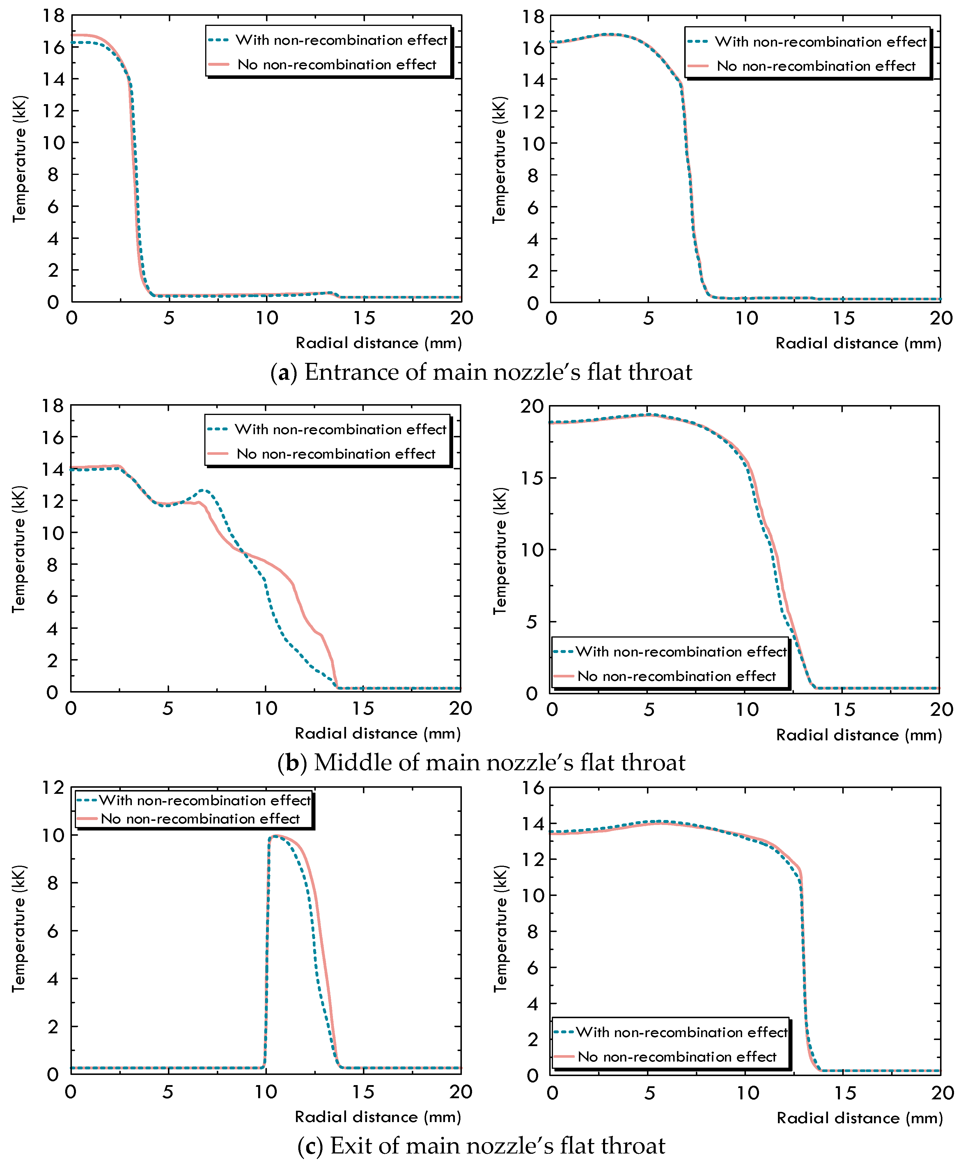
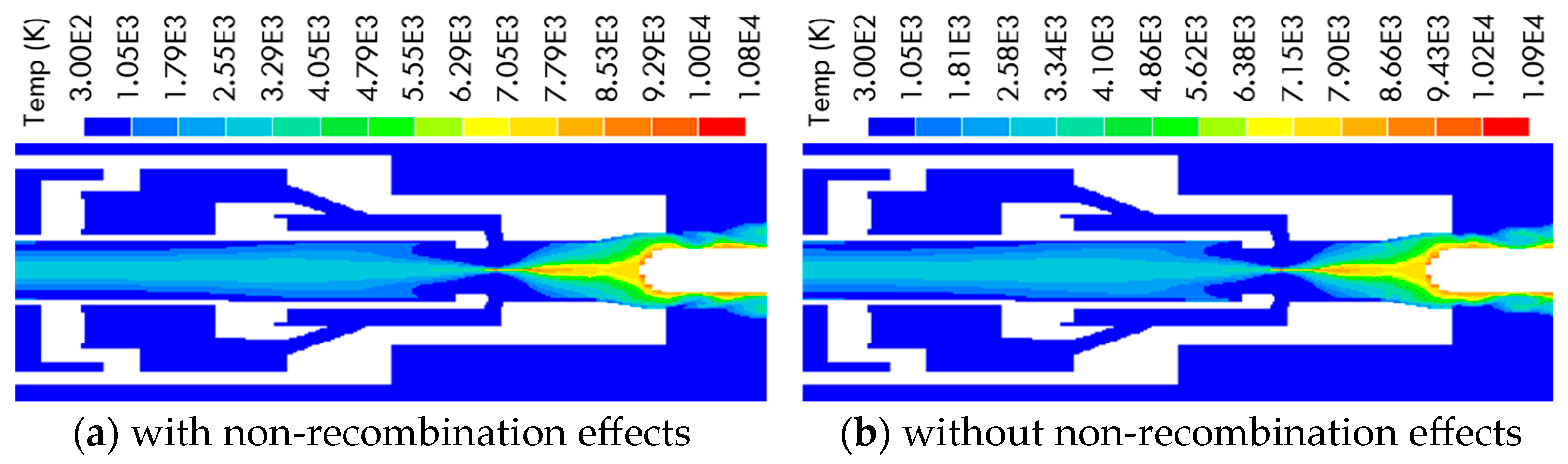
2.2. Difference of Arc Characteristics Caused by the Non-Recombination of C4F7N

A puffer-type model circuit breaker is used in the present work to evaluate the arc characteristics of the C4F7N/CO2 gas mixture. Its schematic diagram is presented in Figure 2. In the present work, the piston inside the puffer cylinder and the solid contact are made to be the moving components to simply the calculation. The mathematic model has been verified in a previous work comparing the pressure distribution and the arc voltage in a circuit breaker [21,29]. The corresponding parameters used in the radiation model and PML model were also calibrated through the comparison to ensure the computational results match the measurements reasonably well.
To analyze the difference in arc dynamic characteristics caused by the modifications of the gas thermophysical properties, two sets of calculations are carried out separately, one without considering the non-recombination feature of C4F7N and the other with it taken into account. Figure 3 illustrates the pressure change inside the puffer cylinder at point A (Figure 2). From the comparison, it is found that the pressurization during the entire arcing process is relatively higher when considering the non-recombination of C4F7N, and this is attributed to the higher mass density for the unreacted gas mixture. The pressure highly depends on the mass density of the gas mixture inside the puffer cylinder, and a higher mass density of the unreacted gas mixture leads to a higher pressurization. The maximum pressure under the unreacted gas mixture is 0.78 MPa, while it is 0.76 MPa for the arced gas mixture. The arc is initiated roughly at 60.8 ms with a negligible pressurization of 0.023 MPa, which is generated by the gas being compressed due to the piston movement at the beginning. As the solid contact moves, the arc is lengthened and fully filled within the arcing space. This movement along with the current change and piston motion generates a strong gas flow and pressure oscillation. From 60.8 ms to 68.9 ms, the current initially increases to its peak value and then gradually decreases to the zero point in its negative half wave, resulting in an increase and subsequent fall in pressure. In addition, the solid contact still blocks the main nozzle during this period, and a relatively larger diameter of the main nozzle’s flat throat for the puffer-type circuit breaker decreases the effects of nozzle clogging. This results in the pressure variation inside the puffer cylinder, which is directly dependent on the piston compression rather than the gas backflow due to nozzle clogging.
Figure 4 presents a comparison of the radial temperature profile in the arcing space with and without the considerations of C4F7N’s non-recombination characteristic. At 68.0 ms, the solid contact moves to the middle of the main nozzle’s flat throat, the nozzle is clogged, and the flow environment is not established sufficiently. Only a small amount of the cold unreacted gas inside the puffer cylinder flows out, and the overall temperature distribution of the arc remains relatively consistent, showing no significant differences. At the entrance of the main nozzle’s flat throat (Figure 4a), the maximum temperature within the arc core is slightly higher when the non-recombination feature is considered in the calculation. The difference in the radius of the arc column is negligible. In front of the solid contact tip, the arc temperature fluctuates, and the arc column also becomes thinner (Figure 4b, left). This is attributed to the blockage effect of the solid contact and the low temperature adjacent to the solid contact surface. At the exit of the main nozzle’s flat throat (Figure 4c, left), it is also found that the overall temperature is slightly higher without considering the non-recombination feature of C4F7N. At 77.0 ms, the current decreases to 15 kA, the solid contact has already been moved out of the main nozzle’s flat throat, and the gas flow channel has also been completely cleared, but the arc temperature still has not changed significantly. It can be pointed out that the consideration of the non-recombination feature for the C4F7N gas only causes a relatively small difference in the arc temperature. This is because the temperature of the gas within the arcing space stays high, and the unreacted gas mixture will be inevitably dissociated or ionized when entering the hot arc column, immediately being converted into the arced gas mixture. This indicates that the arced gas mixture would occupy the greatest area in the arcing space.
However, the pressurization inside the puffer cylinder is comparatively higher with the consideration of C4F7N’s non-recombination feature when calculating the thermophysical properties of the C4F7N/CO2 gas mixture. From Figure 5a (left), it can be seen that the pressure within the arc core region is comparable to that inside the puffer cylinder. However, as shown in Figure 5a (right), when non-recombination effects are not considered, the pressure is 0.06 MPa higher in the upstream puffer cylinder. A stronger cold gas flow with a faster mass flow rate would be driven out towards the arcing space due to the lower pressure difference between the puffer cylinder and middle position of main nozzle’s flat throat or a higher pressure difference between the heating channel and exit of main nozzle, as shown in Figure 6. This indicates that the cold gas flow exerts a stronger blowing effect, and there would be more space for the arc column to deform freely. This also explains why the arc column is thinner when non-recombination effects are considered. When the solid contact clears the main nozzle, the pressure within the arc core region becomes higher than that in the puffer cylinder for both cases with a similar distribution (Figure 5b). At this stage, the temperature in arc region is predominantly influenced by the surrounding pressure field.
Figure 6 shows the temperature distribution of the arc at the final current zero point. During the current zero phase, most of the gas inside the puffer cylinder flowed out to cool the arc. The arc-quenching capability at the current zero point primarily depends on the axial flow field environment surrounding the arc column, which is a combined effect of the gas density and its velocity, determining the mass flow rate. Our calculations reveal that the gas flowed out from the puffer cylinder with a mass flow rate of 14 g/s and 5.7 g/s for the two cases, and the higher mass flow rate resulted from the relatively higher pressure. However, their mass flow rates through the main nozzle are quite similar, 121.2 g/s and 121.0 g/s, indicating that there would not be a difference in the arc temperature.

3. Effects of Configuration Change on Arc Characteristics for C4F7N/CO2 Gas Mixture

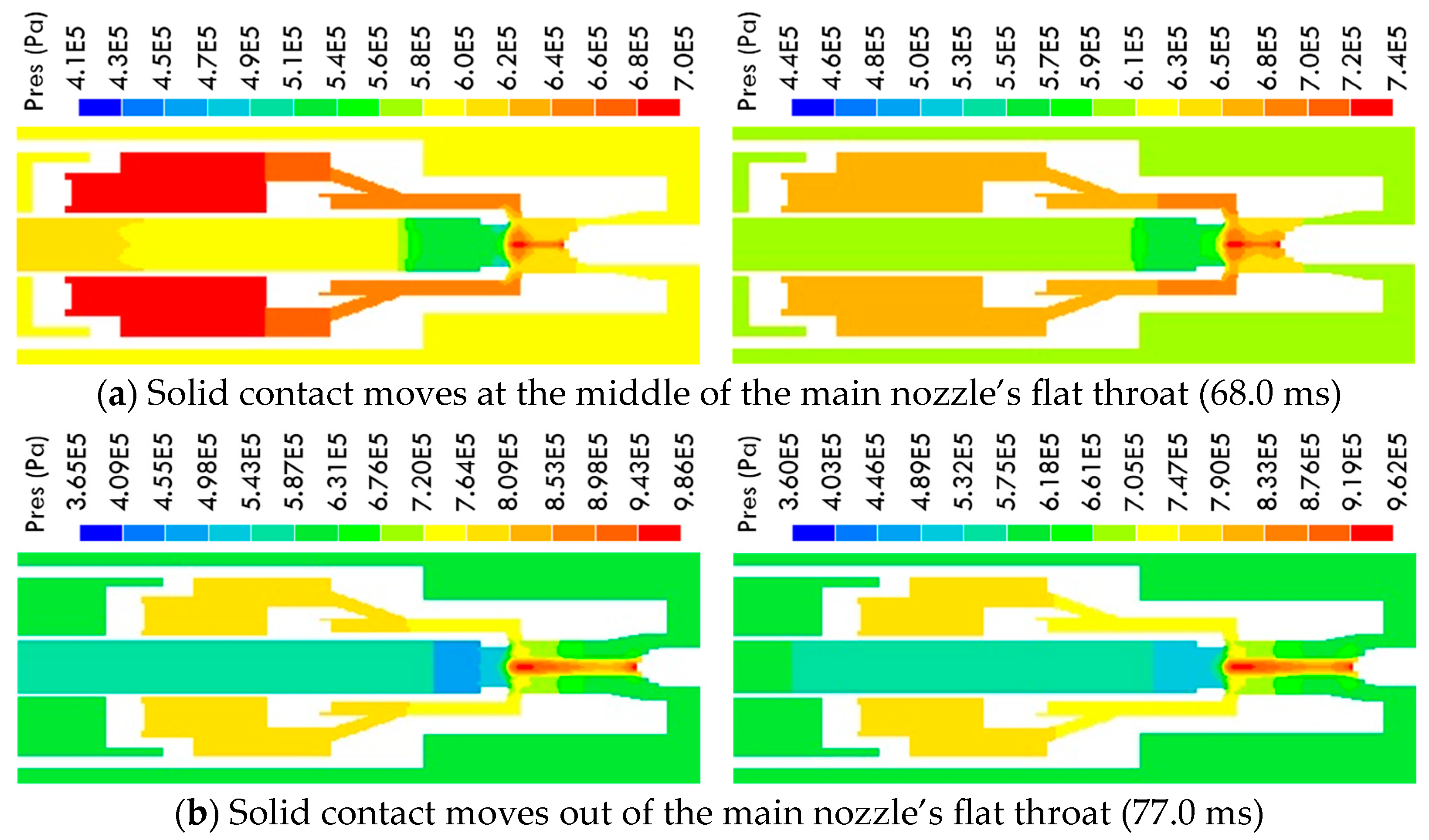
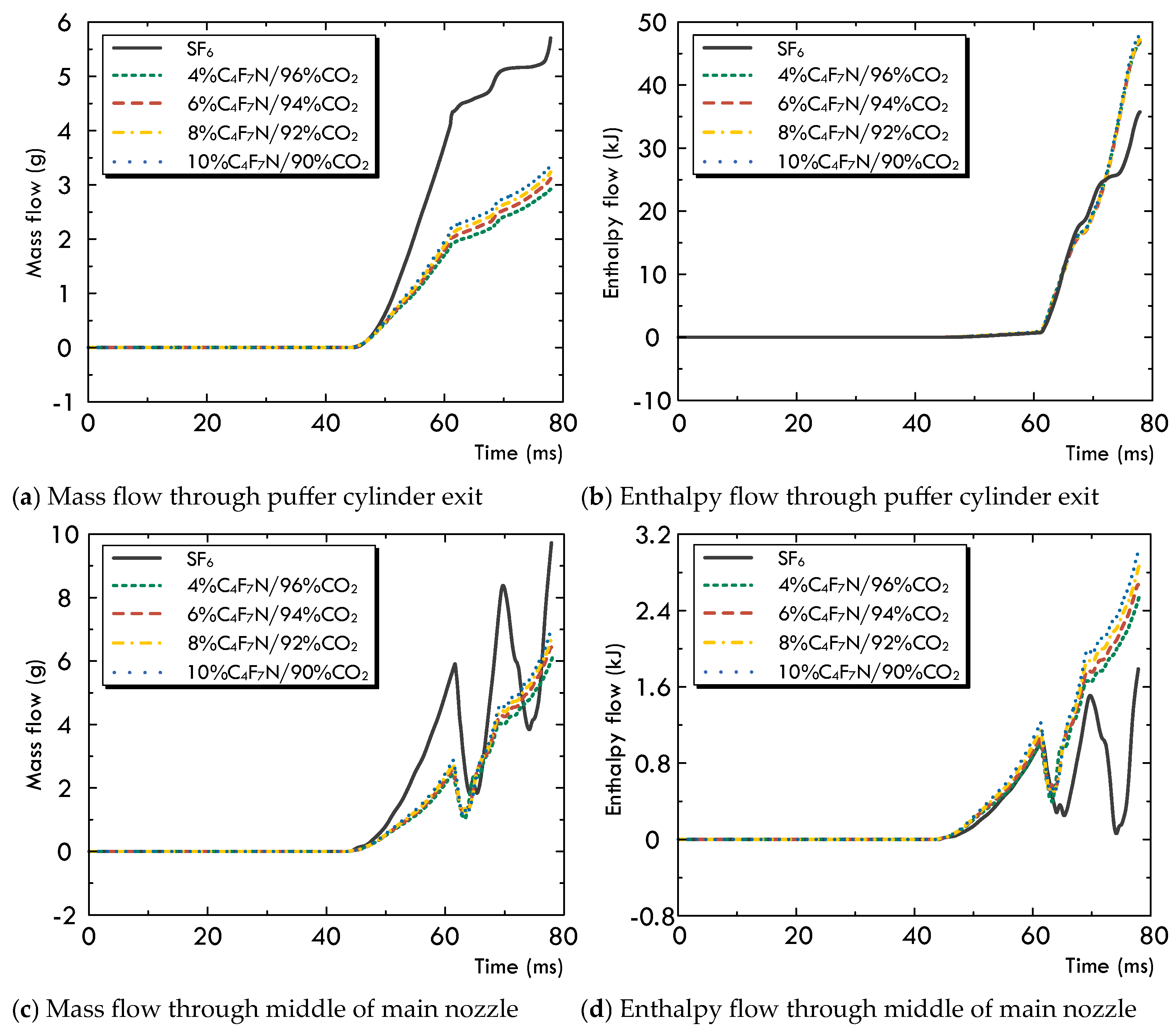
3.1. Variation in the Multi-Physical Fields under High-Current Phase

The effects of the configuration change on the arc dynamic behavior of the C4F7N/CO2 gas mixture are further analyzed with the consideration of the non-recombination feature of C4F7N. The temperature distributions of the arc under the C4F7N/CO2 gas mixture with different mixing ratios in comparison with those of SF6 are shown in Figure 7. From this comparison, it is found that the overall arc radial temperature of SF6 is higher than that of the C4F7N/CO2 gas mixture. The arc radius, defined as the distance from the axis to the temperature isotherm, is 0.83, and the Tmax for SF6 is also smaller.
When the solid contact moves at the middle of the main nozzle’s flat throat at 68.0 ms, the calculation results reveal that the temperature of SF6 within the arc core region in front of the solid contact tip is much higher than the C4F7N/CO2 gas mixtures, while the arc column for the SF6 gas is relatively thinner than that of the gas mixture, and its temperature decrease also seems faster. Actually, the radial temperature profile changes substantially along the length of the arc column. During the high-current phase, the high temperature is primarily determined by ohmic heating and radiation since these two factors dominate the energy transport process. The rather minor change in the temperature inside the arc core is predominantly determined by radiation transport. The temperature within the arc core is also significantly higher than that of the surrounding gas flow, resulting in a steep variation in the radial temperature towards the arc boundary. A faster decrease in temperature indicates a more sufficient thermal energy exchange between the hot arc column and the surrounding cold gas. This means that the radial energy transport for SF6 is much stronger than that of the C4F7N/CO2 gas mixtures.
However, it should be mentioned that changing the volume concentration of C4F7N from 4% to 10% results in a minor difference in the arc radial temperature. The radial temperature of SF6 within the contact space consistently remains higher than that of the C4F7N/CO2 gas mixtures with the solid contact movement, as well as the thinner arc column, which is determined by the higher pressure inside the puffer cylinder. As explained previously, the mass density of SF6 is larger than that of the C4F7N/CO2 gas mixture, which results in a higher pressurization, and this higher pressure drives the cold gas flowing out towards the arcing space with a faster velocity to take away the thermal energy generated from the arc. Moreover, the accumulated ohmic heat generated by the electric power supply for the SF6 and C4F7N/CO2 gas mixtures during the high-current phase is roughly 170.7 kJ and 198.1 kJ, while their radiation loss values are, respectively, 135.2 kJ and 176.6 kJ. It should be noted that a smaller difference between these two factors for the C4F7N/CO2 gas mixture results in a lower arc temperature within the arc core region.
In the calculation of gas thermophysical properties, enthalpy h is the integral value of the specific heat at a constant pressure c p with respect to temperature. The dissociation and ionization reactions occurring in the plasma system largely affect the values of h and c p . The two thermophysical terms of ρ c p and ρ h could reasonably reflect the thermal conduction and convection capabilities of the arc within the radial and axial directions. From Figure 8, it is found that the value of ρ c p for SF6 is much smaller when the temperature becomes higher than 10,000 K, and it presents a negligible difference to that of the C4F7N/CO2 gas mixtures. Within the temperature range from 5000 K to 10,000 K, the values of ρ c p for the C4F7N/CO2 gas mixtures become slightly higher than those of the SF6, while the value of ρ c p for SF6 considerably increases for temperatures below 5000 K. This phenomenon also precisely explains the variation in the radial temperature for the gas. The significantly higher ρ c p of the SF6 at low temperatures indicates a stronger radial thermal conduction around the arc boundary, leading to the arc temperature dropping rapidly. In the comparison of ρ h , the corresponding value for the SF6 is larger than that of the C4F7N/CO2 gas mixtures when the temperature is below 6000 K, while it conversely becomes smaller at temperatures above 6000 K. The larger value of ρ h implies a stronger axial convection, and the arc length for the C4F7N/CO2 gas mixture would thus become longer in the axial direction. However, during the current zero phase, the electrical energy power supplied to the arc becomes lower due to the current decrease. The arc temperature also becomes lower. The larger values of ρ c p and ρ h for the SF6 indicate much stronger thermal conduction and axial convection effects, and its arc temperature is reduced rapidly. For the C4F7N/CO2 gas mixture, a weaker energy exchange consequently leads to a high temperature of the gas, and the longer arc inevitably results in a much greater area covered the hot gas flow as well. This is not conducive for arc cooling. In addition, the similar temperature distributions for the C4F7N/CO2 gas mixture with different mixing ratios are also determined by their similar thermophysical properties, resulting in comparable arc-quenching performances.
Figure 9 presents the pressure and mass density variations inside the puffer cylinder for different gases. The maximum pressure for SF6 during the entire arcing process is 1.26 MPa, while that for the C4F7N/CO2 gas mixtures is roughly within the range between 0.78 MPa and 0.82 MPa. The much higher pressure for SF6 is attributed to its higher mass density at low temperatures, which results in a stronger gas compression effect. For the puffer-type circuit breaker, the pressurization inside the upstream puffer cylinder is predominantly determined through the gas compression by the piston movement. Throughout the whole arcing process, the hot gas actually does not flow in reverse back to the puffer cylinder from the arc region, so the temperature of the gas in the puffer cylinder remains lower and the gas density becomes the dominant factor influencing the pressure distribution. Moreover, the mass density also grows with the volume concentration of C4F7N as a result of the corresponding increase in mass density for the gas mixture. A smaller pressure difference between the puffer cylinder and contact gap would also generate a high-speed gas flow through the nozzle to cool the hot arc.
As shown in Figure 10, the calculation results also reveal that the axial gas flow velocity of the SF6 is faster than that of the C4F7N/CO2 gas mixture. When the volume concentration of C4F7N in the gas mixture increases from 4% to 10%, the axial velocity only shows a minor increase, which is attributed to the smaller difference in pressure inside the arcing chamber and similar thermophysical properties. Moreover, the gas’s axial convection capability is also affected by the combination of the axial gas flow velocity and ρ h . It is observed that the axial velocity of the gas near the solid contact’s upper surface is larger and the area covered by this high-velocity gas far exceeds that of the SF6 because of its larger ρ h value. The axial velocity also presents a continuous increase with the solid contact’s movement, especially when it completely clears the main nozzle’s flat throat.

3.2. Arc Characteristics under Current Zero Phase

The position of the solid contact determines the effective cross-sectional area that is exposed to the arc. In the present case, the solid contact has already cleared the main nozzle’s flat throat, a strong axial flow has been established, and turbulence cooling plays a dominant role in the energy exchange. As shown in Figure 11, it is observed from the comparison that the arc radius between the contact space is the smallest for the SF6 as well as the gas flow temperature. The temperature distributions for the C4F7N/CO2 gas mixture present a similar pattern with minor differences, although the volume concentration of the C4F7N increases from 4% to 10%. The maximum value only slightly increases from 10,800 K to 11,000 K. Furthermore, the arc column is significantly elongated for the C4F7N/CO2 gas mixture compared to that of the SF6 in the axial direction. Moreover, the area covered by the hot gas is also significantly large, which further supports the previous discussion. This indicates that the gas-blowing effect in the SF6 atmosphere is stronger at the current zero phase under the same operating conditions.
As explained previously, the turbulence-enhanced momentum and energy transfer are most significant during the current zero phase. Closely associated with the surrounding cold gas flow, the arc temperature on the axis exhibits two peaks at the final current zero point, one near the tip of the solid contact and the other near the entrance of the main nozzle’s flat throat. The cooling of the arc is predominantly controlled by the mass flow rate through the nozzle.
Figure 12 presents the gas flow through the puffer cylinder and the main nozzle’s flat throat, respectively. The rates of mass flow and enthalpy flow, respectively, depend on the two terms of ρ w and ρ w h . From the puffer cylinder towards the main nozzle’s flat throat, the accumulated mass flux for SF6 is significantly larger than that of the C4F7N/CO2 gas mixture, while its total enthalpy flux is relatively lower. The corresponding larger mass flux is mainly attributed to its faster axial velocity as well as its mass density. In addition, the total mass flux considerably increases with a higher flow rate for the SF6 especially after 77.0 ms during the current zero phase. This indicates that the gas rushes out from the puffer cylinder with a low temperature and high mass flux. The cooling effect is more affected by the cold gas mass flux than the enthalpy flux. Moreover, the cooling effect for SF6 appears to be stronger. For the C4F7N/CO2 gas mixture with different mixing ratios, it is also observed that both the mass and enthalpy fluxes through the puffer cylinder exit become larger with the increased volume concentration of C4F7N, while the enthalpy fluxes through the main nozzle’s flat throat remain almost unchanged.
Figure 13 presents the predicted arc voltage for the different gases. During the high-current phase, the overall arc voltage of SF6 is relatively lower than that of the C4F7N/CO2 gas mixture. Furthermore, the predicted peak value of the arc voltage for SF6 (1575 V) at the final current zero point is also significantly higher while the value for the C4F7N/CO2 gas mixture presents an obvious decrease, ranging from 880 V to 916 V. The peak voltage can reasonably describe the de-ionization strength of the gas during the post arc phase. A higher voltage indicates a stronger de-ionization effect, and its corresponding arc-extinguishing performance is better.

4. Conclusions

The arc dynamic characteristics of the C4F7N/CO2 gas mixture are comparatively studied in the present work to thoroughly analyze the difference between its arc performance and that of SF6. From our research, the following conclusions can be drawn:
(1)
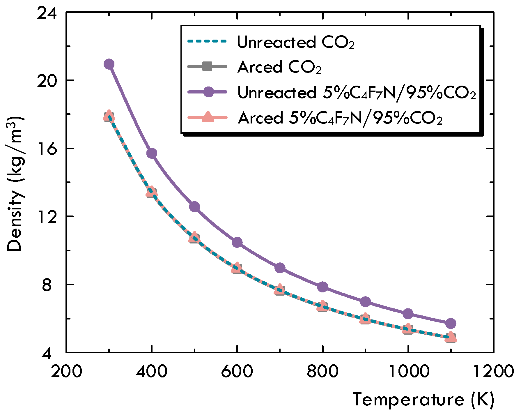
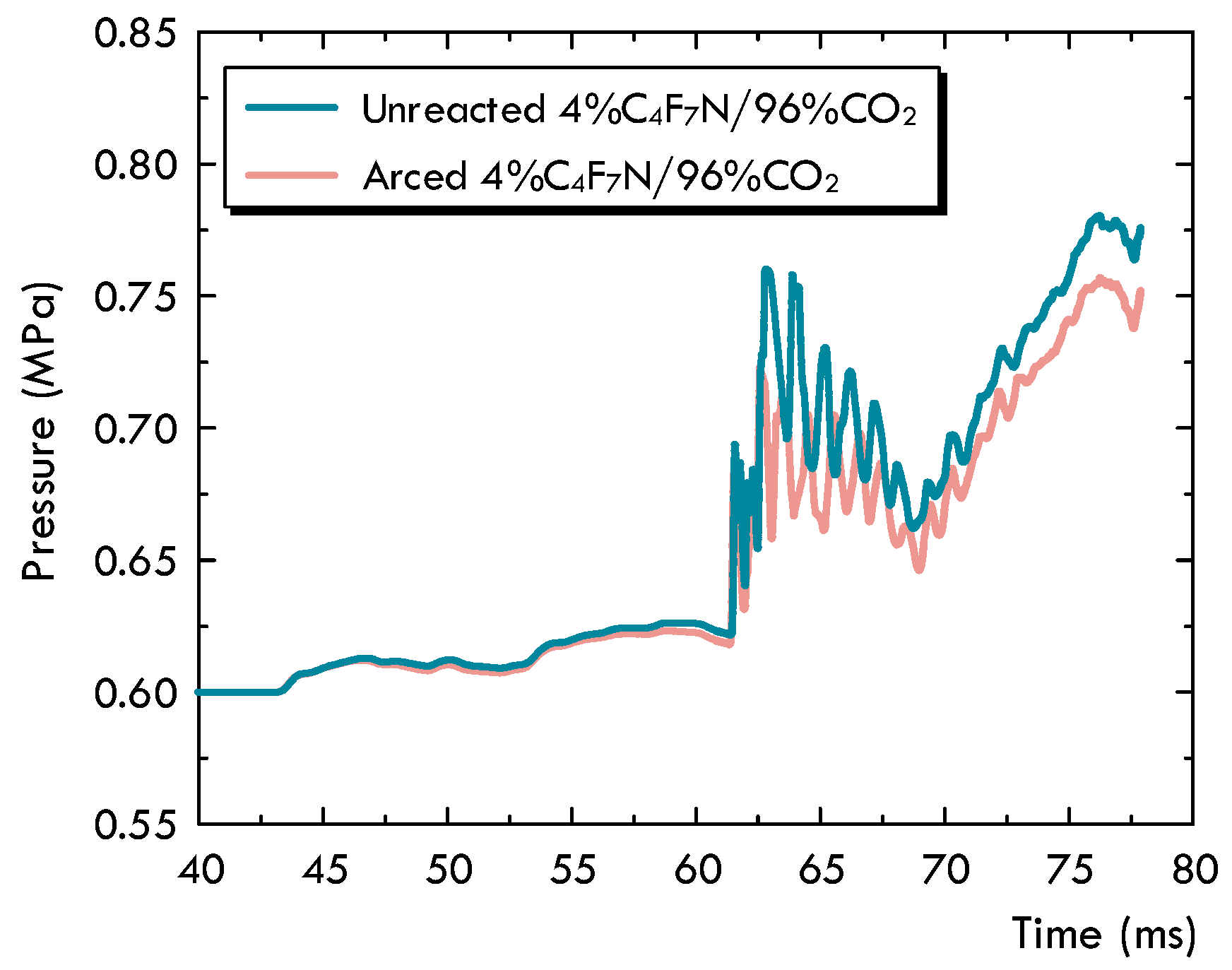
Based on the decomposition characteristics for the C4F7N and C4F7N/CO2 gas mixture, the existing MHD-based two-dimensional arc model is innovatively modified to handle the non-recombination feature of C4F7N. It is proposed to differentiate the unreacted gas mixture, as initially filled in a circuit breaker without experiencing any significant dissociation, from the arced gas mixture, which is referred to as the LTE-LCE gas mixture. A species concentration equation is solved to keep track of the concentration of the arced gas mixture, and a method is advised to allow the transfer between the two sets of material properties. From the comparison, it is found that the most noticeable impact of the gas’s non-recombination feature is the pressurization inside the puffer cylinder. With this consideration, the pressure for the cold gas becomes higher, and it will definitely establish better distributions of the flow field conditions during the arcing process.
(2)
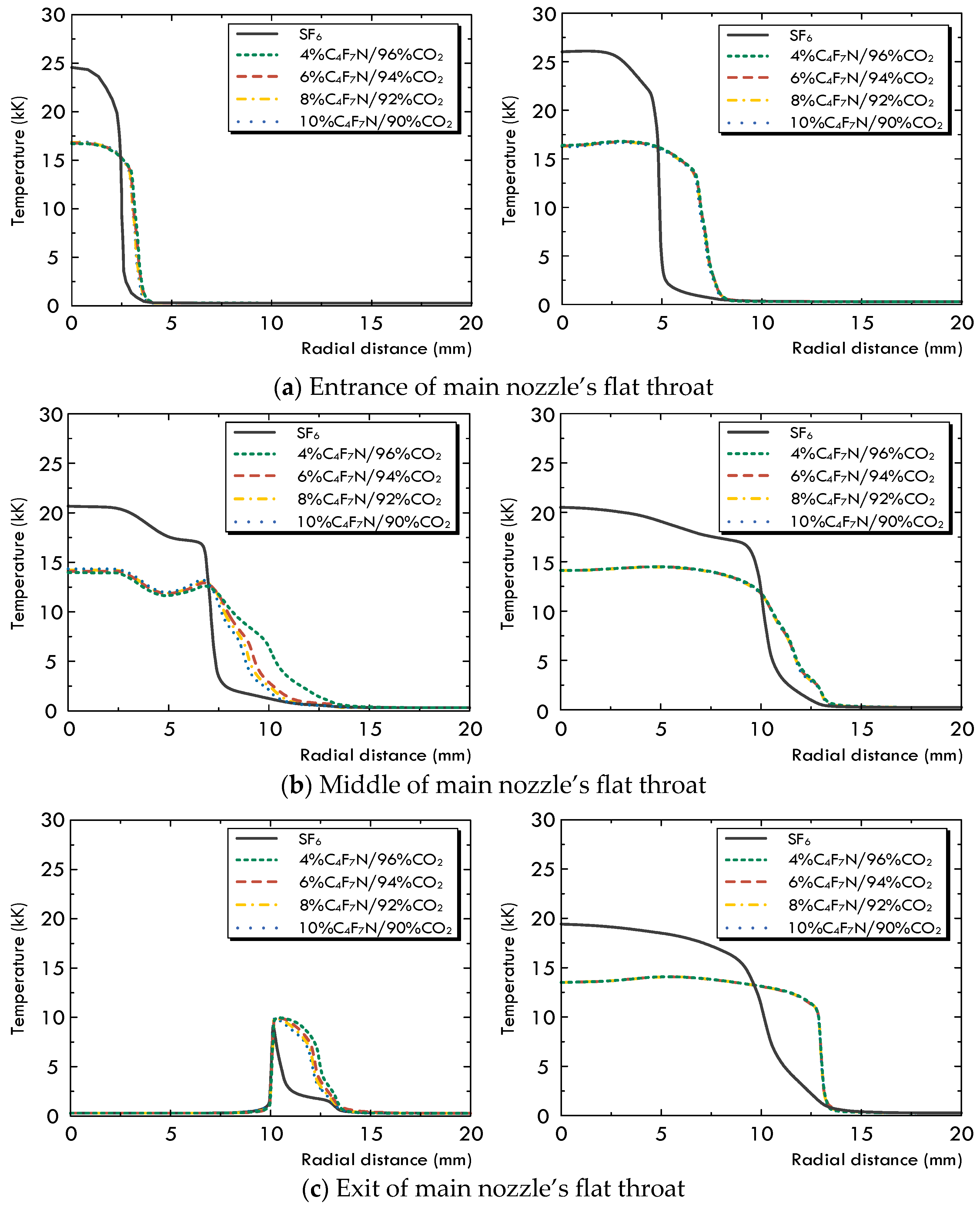
The diffusing, multi-physical field characteristics and flow field conditions of the arc for the C4F7N/CO2 gas mixture are slightly affected by changing the volume concentration of C4F7N. An increase from 4% to 10% leads to a slightly higher pressure and larger mass and enthalpy fluxes through the arcing chamber, which improve its corresponding arc-extinguishing performance.
(3)
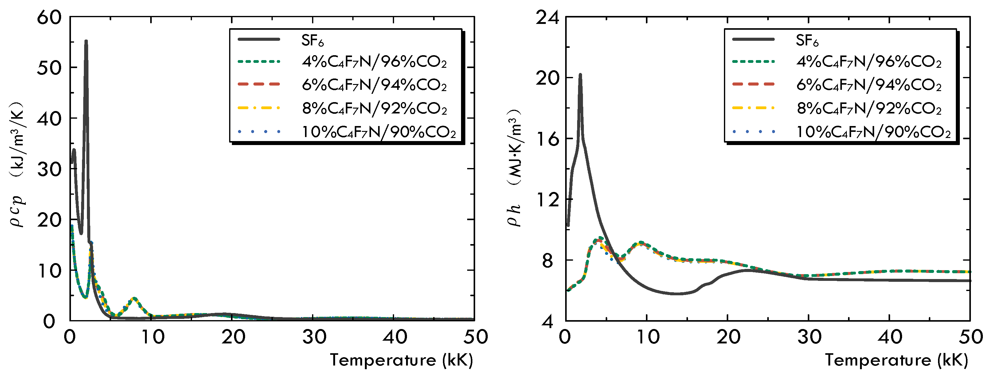
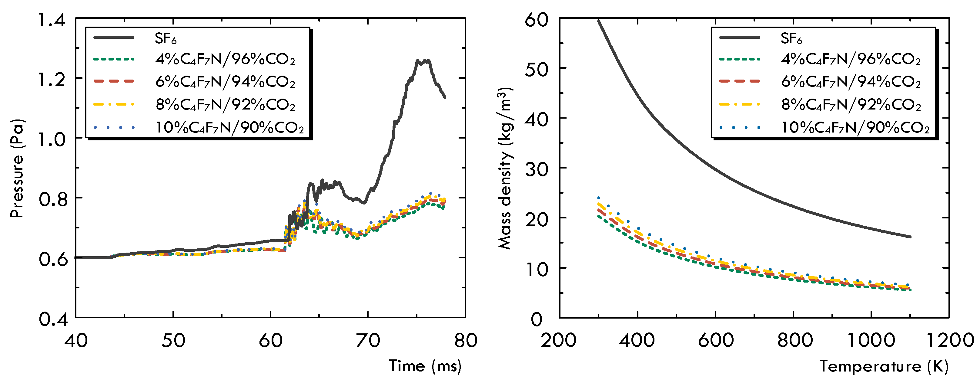
In comparison with SF6 under the same operation conditions, the first difference is that the pressurization effect of the SF6 gas inside the upstream puffer cylinder is significantly superior to that of the C4F7N/CO2 gas mixture. Secondly, due to the noticeable higher values of both ρ h and ρ c p at low temperatures, the arc diffusion in the SF6 gas atmosphere is well controlled both in the axial and radial directions. In the C4F7N/CO2 gas mixture, the longer axial diffusion of the arc significantly deteriorates its post-arc recovery characteristics. This indicates that using the C4F7N/CO2 gas mixture as an arc-extinguishing medium requires the optimization of the mechanical characteristics of the driving mechanism, such as increasing its moving velocity, as well as improvements in the design of the puffer cylinder or nozzle geometry of the arc chamber.

Author Contributions

Conceptualization, W.W.; Data curation, W.W. and Y.B.; Formal analysis, W.W.; Funding acquisition, X.Y.; Investigation, B.L.; Methodology, W.W.; Project administration, X.Y.; Software, W.W. and Y.B.; Supervision, X.Y. and B.L.; Validation, X.Y. and B.L.; Writing—original draft, W.W. All authors have read and agreed to the published version of the manuscript.

Funding

This work was supported by Science and Technology Projects of State Grid Corporation of China (GY84-22-001&5108-202218280A-2-219-XG).

Data Availability Statement

Data are contained within the article.

Conflicts of Interest

Authors Wen Wang, Xianglian Yan, Beiyang Liu and Yanlin Bian were employed by the company China Electric Power Research Institute. The remaining authors declare that the research was conducted in the absence of any commercial or financial relationships that could be construed as a potential conflict of interest.

References

  1. The Intergovernmental Panel on Climate Change (IPCC). FAR Climate Change: Scientific Assessment of Climate Change; IPCC: Geneva, Switzerland, 2010. [Google Scholar]
  2. Forster, P.; Storelvmo, T.; Armour, K.; Collins, W.; Dufresne, J.-L.; Frame, D.; Lunt, D.J.; Mauritsen, T.; Palmer, M.D.; Watanabe, M. IPCC Sixth Assessment Report Working Group I: The Physical Science Basis—Chapter 07: The Earth’s Energy Budget, Climate Feedbacks, and Climate Sensitivity; Cambridge University Press: Cambridge, UK, 2021. [Google Scholar]
  3. Mantilla, J.; Claessens, M.; Kriegel, M. Environmentally Friendly Perfluoroketones-Based Mixture as Switching Medium in High Voltage Circuit Breakers; A3-113; CIGRE: Paris, France, 2016. [Google Scholar]
  4. Gautschi, D.; Ficheux, A.; Walter, M.; Vuachet, J. Application of a Fluoronitrile Gas in GIS and GIL as an Environmental Friendly Alternative to SF6; B3-106; CIGRE: Paris, France, 2016. [Google Scholar]
  5. Zhang, B.Y.; Zhou, R.; Wang, K.; Guo, Z.; Li, X.W.; Cao, M.C.; Deng, J.W.; Wang, D.B. Arc Interruption Performance of C4F7N-CO2 Mixture in a 126 kV Disconnector. IEEE Trans. Power Deliv. 2023, 38, 1197–1207. [Google Scholar] [CrossRef]
  6. Uchii, T.; Shinkai, T.; Suzuki, K. Thermal interruption capability of carbon dioxide in a puffer-type circuit breaker utilizing polymer ablation. In Proceedings of the IEEE/PES Transmission and Distribution Conference and Exhibition, Yokohama, Japan, 6–10 October 2002; pp. 1750–1754. [Google Scholar]
  7. Meijer, S.; Smit, J.J.; Girodet, A. Comparison of the breakdown strength of N2, CO2 and SF6 using the extended up-and-down method. In Proceedings of the IEEE 8th International Conference on Properties & Applications of Dielectric Material, Bali, Indonesia, 26–30 June 2006; pp. 653–656. [Google Scholar]
  8. Stoller, P.C.; Seeger, M.; Iordanidis, A.A.; Naidis, G.V. CO2 as an Arc interruption medium in gas circuit breakers. IEEE Trans. Plasma Sci. 2013, 41, 2359–2369. [Google Scholar] [CrossRef]
  9. Chervy, B.; Gonzalez, J.J.; Gleizes, A. Calculation of the interruption capability of SF6-CF4 and SF6-C2F6 mixtures-Part II: Arc decay modeling. IEEE Trans. Plasma Sci. 1996, 24, 198–209. [Google Scholar] [CrossRef]
  10. Yang, W.H.; Wang, Z.J.; Wang, D.B.; Chen, Q.L.; Zhao, S.C.; Zhuo, R. Arc interruption performance of SF6/N2 gas and dielectric recovery in disconnector. In Proceedings of the 2023 4th International Symposium on Insulation and Discharge Computation for Power Equipment, IDCOMPU2023, Wuhan, China, 26–28 May 2023; pp. 149–156. [Google Scholar]
  11. Zhao, H.; Li, X.W.; Zhu, K.; Wang, Q.; Lin, H.; Guo, X.X. Study of the arc interruption performance of SF6-CO2 mixtures as a substitute for SF6. IEEE Trans. Dielectr. Electr. Insul. 2016, 23, 2657–2667. [Google Scholar] [CrossRef]
  12. Nechmi, H.E.; Beroual, A.; Girodet, A.; Vinson, P. Fluoronitriles/CO2 gas mixture as promising substitute to SF6 for insulation in high voltage applications. IEEE Trans. Dielectr. Electr. Insul. 2016, 23, 2587–2593. [Google Scholar] [CrossRef]
  13. Li, Y.; Zhang, X.X.; Chen, Q.; Fu, M.L.; Zhuo, R.; Xiao, S.; Chen, D.C.; Tang, J. Study on the Dielectric Properties of C4F7N/N2 Mixture Under Highly Non-Uniform Electric Field. IEEE Access 2018, 6, 42868–42876. [Google Scholar] [CrossRef]
  14. Zheng, Y.; Zhou, W.J.; Li, H.; Yan, X.L.; Li, Z.B.; Chen, W.J.; Bian, K. Influence of conductor surface roughness on insulation performance of C4F7N/CO2 mixed gas. IEEE Trans. Dielectr. Electr. Insul. 2019, 26, 922–929. [Google Scholar] [CrossRef]
  15. Kieffel, Y.; Biquez, F.; Vigouroux, D.; Ponchon, P.; Schlernitzauer, A.; Magous, R.; Cros, G.; Owens, J.G. Characteristics of g3—An alternative to SF6. In Proceedings of the 2016 IEEE International Conference on Dielectrics (ICD), Montpellier, France, 3–7 July 2016; pp. 54–57. [Google Scholar]
  16. Kieffel, Y.; Biquez, F. SF6 alternative development for high voltage switchgears. In Proceedings of the Electrical Insulation Conference, Denver, CO, USA, 26–30 July 2015; pp. 379–383. [Google Scholar]
  17. Fu, L.J.; Shao, X.J.; Xin, Z.Z.; Xie, C. Experimental Research on Breaking Performance of C4F7N/CO2 Mixed Gas in Medium Voltage Load switch. High Volt. Appar. 2020, 56, 86–91. [Google Scholar]
  18. Song, Y.; Lin, X.; Xu, J.Y.; Zhang, J. Interruption Performance of C4F7N/CO2 Gas in High-voltage Circuit Breaker. High Volt. Eng. 2023, 49, 971–981. [Google Scholar]
  19. Lv, Q.S.; Guo, Z.; Xu, H.Y.; Wang, L.; Li, X.W.; Xiang, Z. Experimental Study on the Free Arc-burning Arc Characteristics of C4F7N/CO2 Mixture. High Volt. Eng. 2019, 445, 3804–3809. [Google Scholar]
  20. Fang, M.T.C.; Brannen, D. A Current-Zero Arc Model Based on Forced Convection. IEEE Trans. Plasma Sci. 1979, 7, 217–229. [Google Scholar] [CrossRef]
  21. Yan, J.D.; Fang, M.T.C.; Hall, W. The development of PC based CAD tools for auto-expansion circuit breaker design. IEEE Trans. Power Deliv. 1999, 14, 176–181. [Google Scholar] [CrossRef]
  22. Wu, Y.; Rong, M.Z.; Yang, Q.; Hu, G.X. Simulation on dynamic characteristics of arc in low voltage circuit breaker modelling. Proc. CSEE 2005, 25, 143–148. [Google Scholar]
  23. Pei, Y.Q.; Zhong, J.Y.; Zhang, J.M.; Yan, J.D. A comparative study of arc behaviour in an auto-expansion circuit breaker with different arc durations. J. Phys. D Appl. Phys. 2014, 47, 335201. [Google Scholar] [CrossRef]
  24. Wu, Y.; Wang, C.L.; Sun, H.; Murphy, A.B.; Rong, M.Z.; Yang, F.; Chen, Z.X.; Niu, C.P.; Wang, X.H. Properties of C4F7N–CO2 thermal plasmas: Thermodynamic properties, transport coefficients and emission coefficients. J. Phys. D Appl. Phys. 2018, 51, 1555206. [Google Scholar] [CrossRef]
  25. Fang, M.T.C.; Zhuang, Q.; Guo, X.J. Current-Zero Behaviour of an SF6 Gas- Blast Arc. II. Turbulent Flow. J. Phys. D Appl. Phys. 1994, 27, 74–83. [Google Scholar] [CrossRef]
  26. Zhang, Q.; Yan, J.D.; Fang, M.T.C. The modelling of an SF 6 arc in a supersonic nozzle: I. Cold flow features and dc arc characteristics. J. Phys. D Appl. Phys. 2014, 47, 215201. [Google Scholar] [CrossRef]
  27. Dixon, C.M.; Yan, J.D.; Fang, M.T.C. A comparison of three radiation models for the calculation of nozzle arcs. J. Phys. D Appl. Phys. 2004, 37, 3309–3318. [Google Scholar] [CrossRef]
  28. Yan, J.D.; Nuttall, K.I.; Fang, M.T.C. A comparative study of turbulence models for SF6 arcs in a supersonic nozzle. J. Phys. D Appl. Phys. 1999, 32, 1401–1406. [Google Scholar] [CrossRef]
  29. Zhang, J.L.; Yan, J.D.; Murphy, A.B.; Hall, W.; Fang, M.T.C. Computational investigation of arc behavior in an auto-expansion circuit breaker contaminated by ablated nozzle vapor. IEEE Trans. Plasma Sci. 2002, 30, 706–719. [Google Scholar] [CrossRef]
Figure 1. Comparison of the mass density of unreacted and arced gas at 10 bar.
Energies 17 03485 g001
Figure 2. Structural design of the model circuit breaker under investigation.
Energies 17 03485 g002
Figure 3. Comparison of pressure difference inside the puffer cylinder with and without the consideration of the non-recombination feature of C4F7N.
Energies 17 03485 g003
Figure 4. Comparison of arc radial temperature at different times, left: t = 68.0 ms; right: t = 77.0 ms.
Energies 17 03485 g004
Figure 5. A comparison of the pressure distribution at different time points; left: considering the non-recombination feature of C4F7N; right: without such consideration.
Energies 17 03485 g005
Figure 6. A comparison of the temperature at the final current zero (77.9 ms).
Energies 17 03485 g006
Figure 7. Comparison of arc radial temperature for different gases at different times, left: t = 68.0 ms; right: t = 77.0 ms.
Energies 17 03485 g007
Figure 8. Comparison of thermophysical properties for different gases at 10 atm.
Energies 17 03485 g008
Figure 9. A comparison of the pressure (left) and mass density (right) of different gases.
Energies 17 03485 g009
Figure 10. Comparison of axial velocity distributions for different gases at two typical time points.
Energies 17 03485 g010
Figure 11. A comparison of arc temperature distribution at the final current zero point.
Energies 17 03485 g011
Figure 12. A comparison of the gas mass and enthalpy flow through different cross-sections inside the arcing chamber.
Energies 17 03485 g012
Figure 13. A comparison of the predicted arc voltage for different gases during the arcing process.
Energies 17 03485 g013
Table 1. Diffusion coefficients and source terms for the governing equations.
Equation ϕ Γ ϕ S ϕ
Mass100
x-Momentumv μ l + μ t P z + J r B θ + viscous terms
y-Momentumw μ l + μ t P r J z B θ + viscous terms
Energyh λ l + λ t c p σ E 2 q + d P d t + viscous dissipation
Arced gas concentration c a r c e d ρ ( D l + D t ) 0
Current continuity φ σ 0
Disclaimer/Publisher’s Note: The statements, opinions and data contained in all publications are solely those of the individual author(s) and contributor(s) and not of MDPI and/or the editor(s). MDPI and/or the editor(s) disclaim responsibility for any injury to people or property resulting from any ideas, methods, instructions or products referred to in the content.

