
Performance Analysis of an Ejector-Enhanced Heat Pump System for Low-Temperature Waste Heat Recovery Using UHVDC Converter Valves

Abstract
:1. Introduction
2. Materials and Methods
2.1. System Description
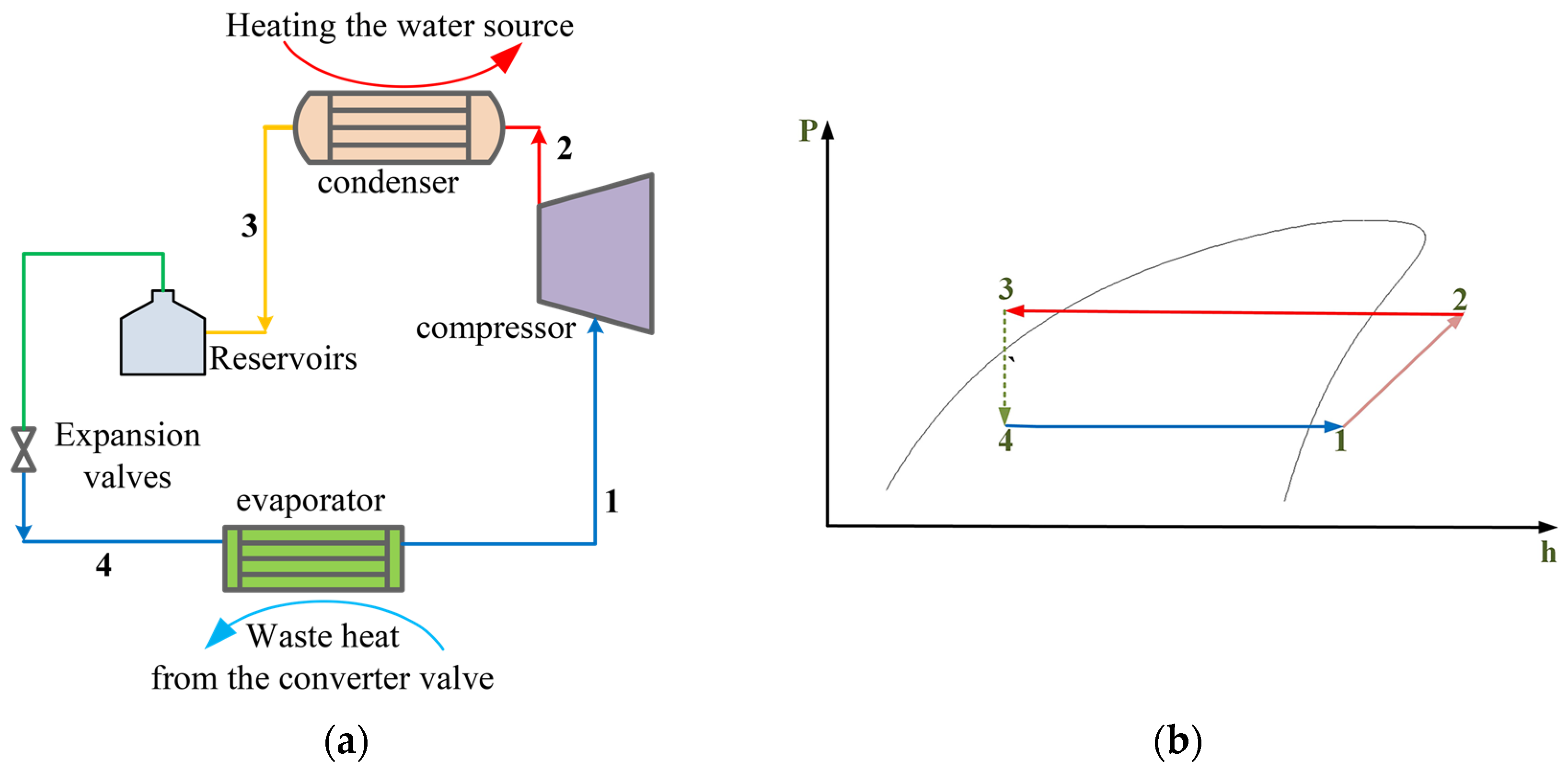
2.1.1. BVCHPS
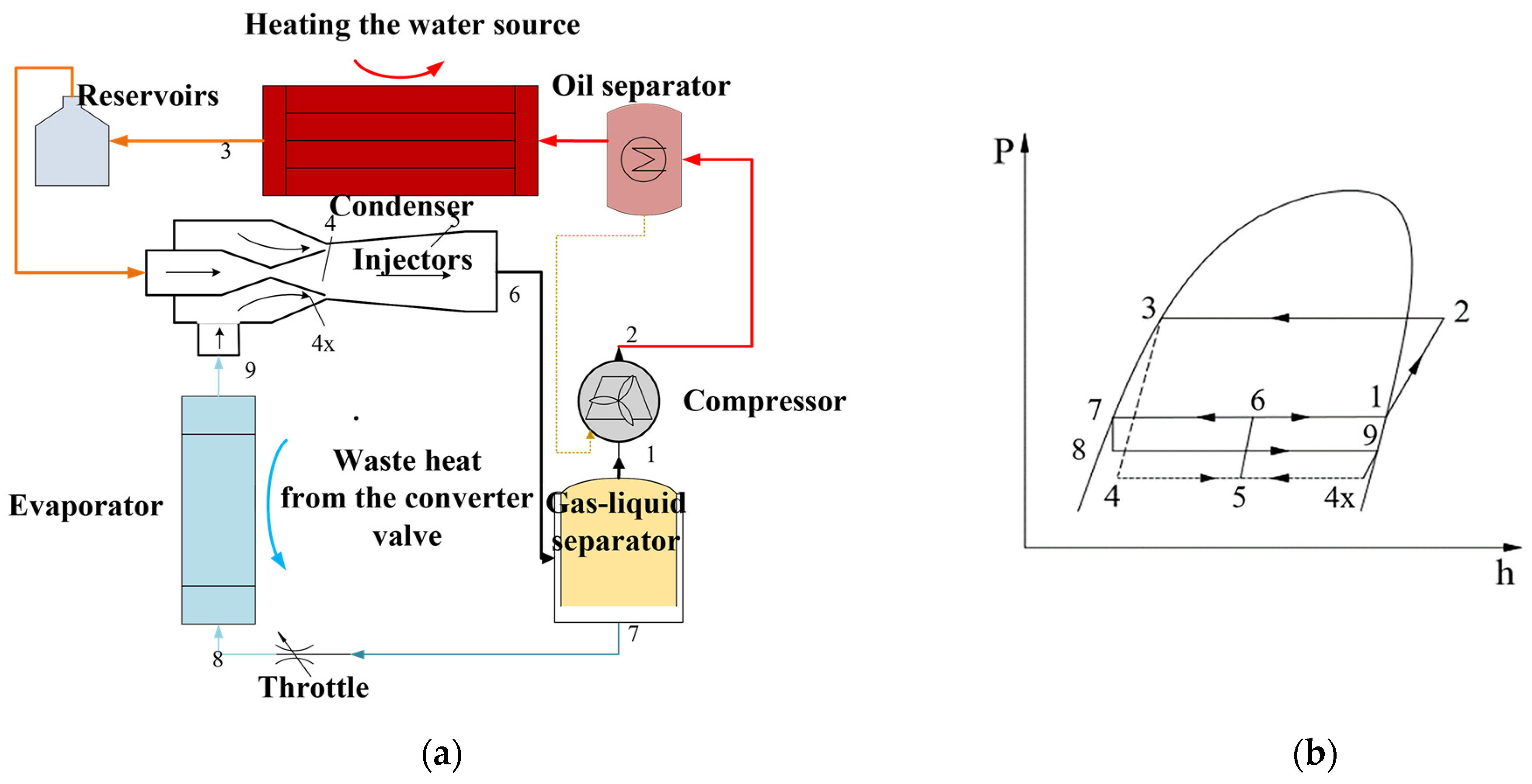
2.1.2. EEHPS
2.2. Thermodynamic Modeling
2.2.1. COP
- BVCHPS
- Condenser
- Evaporator
- Throttle valve
- Compressor
- The heating coefficient of the system
- 2.
- EEHPS
- Evaporator
- Throttle valve
- Compressor
- Gas–liquid separator
- Condenser
- 3.
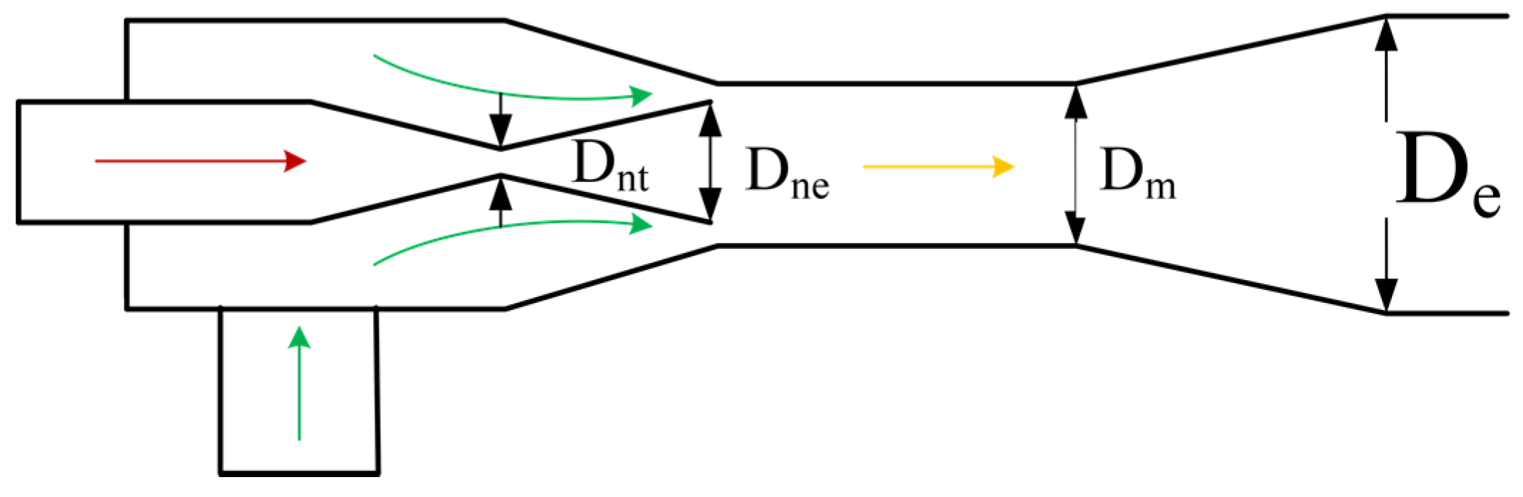
- Ejector
- (a)
- Except for the mixing chamber, the remaining parts of the ejector are in thermodynamic equilibrium, i.e., one-dimensional uniform flow, and the fluid at the nozzle throat reaches a clogged state;
- (b)
- Neglecting the influence of gravity on the fluid, ignoring the heat exchange between the fluid and the ejector wall, ignoring the kinetic energy of the fluid at the inlet of the ejector working nozzle and the inlet of the injection nozzle, and ignoring the kinetic energy of the fluid at the outlet of the ejector expansion chamber;
- (c)
- Adopting isentropic efficiency coefficients for the flow process of fluid in nozzles, suction chambers, and expansion chambers ηn, ηs, and ηD for correction;
- (d)
- Neglecting the pressure drop of fluids in evaporators, condensers, and connecting pipelines;
- (e)
- The system has no subcooling or overheating.
- Nozzle
- Throat to the nozzle outlet
- Ejector suction chamber
- Ejector expansion mixing chamber
- Ejector expansion chamber
2.2.2. Exergy Efficiency
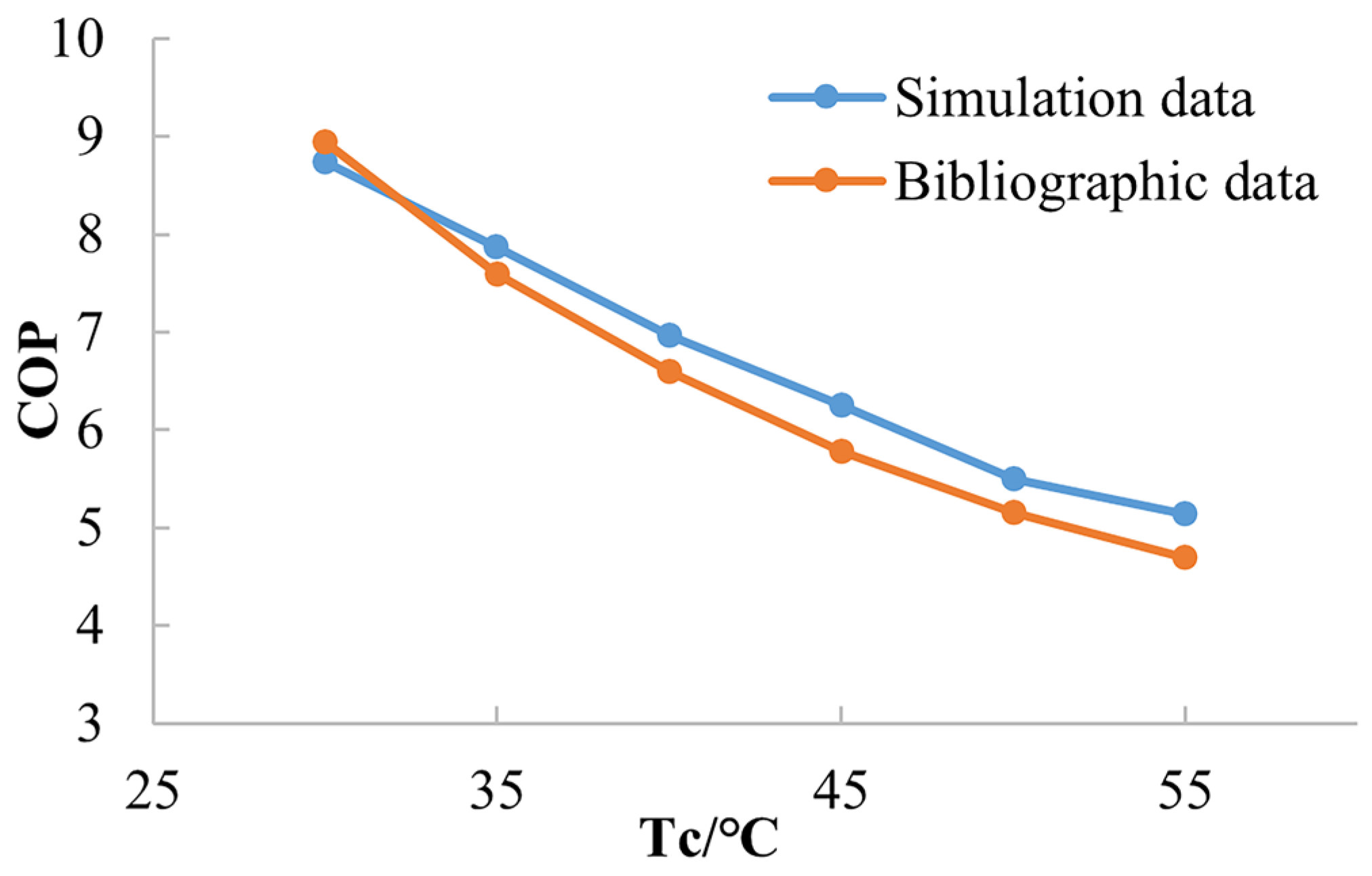
2.3. Model Validation
3. Results
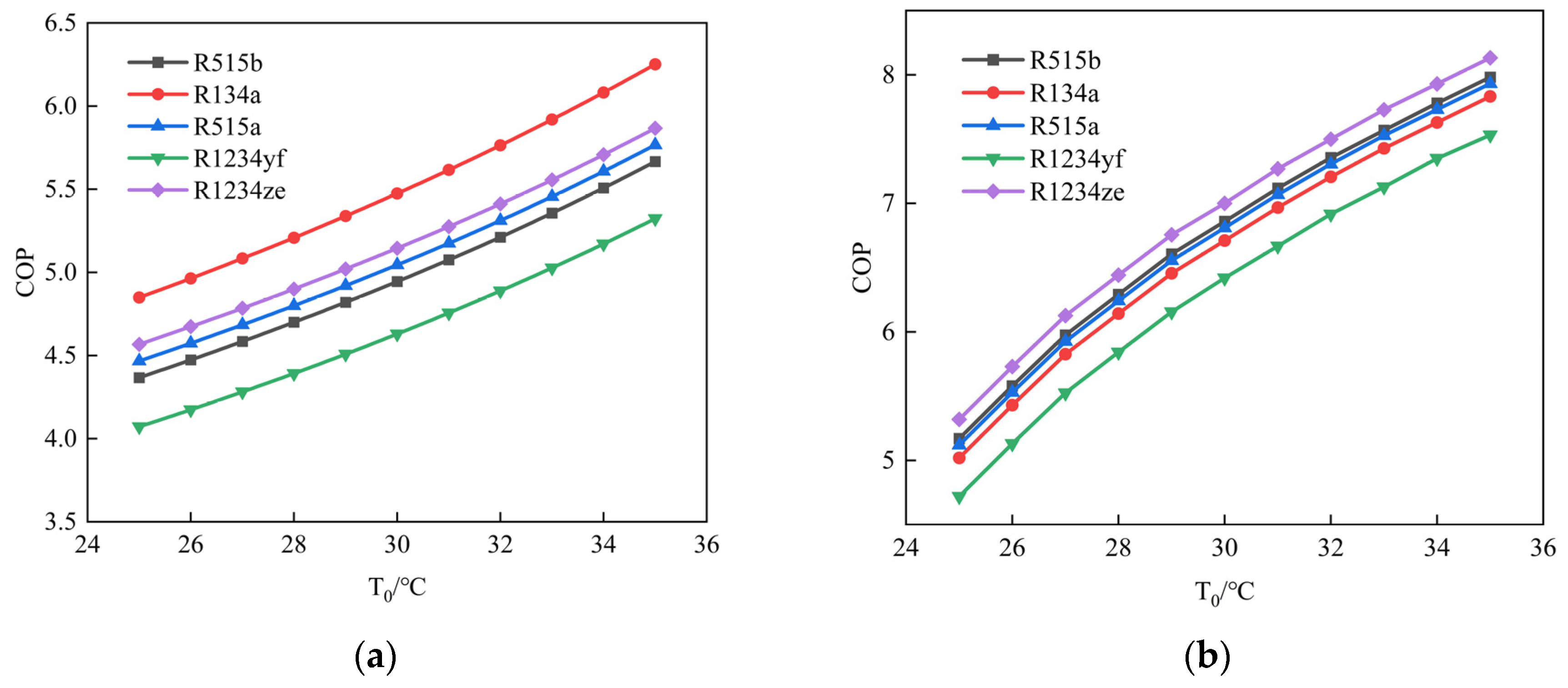
3.1. COP Results
3.2. Exergy Efficiency Results
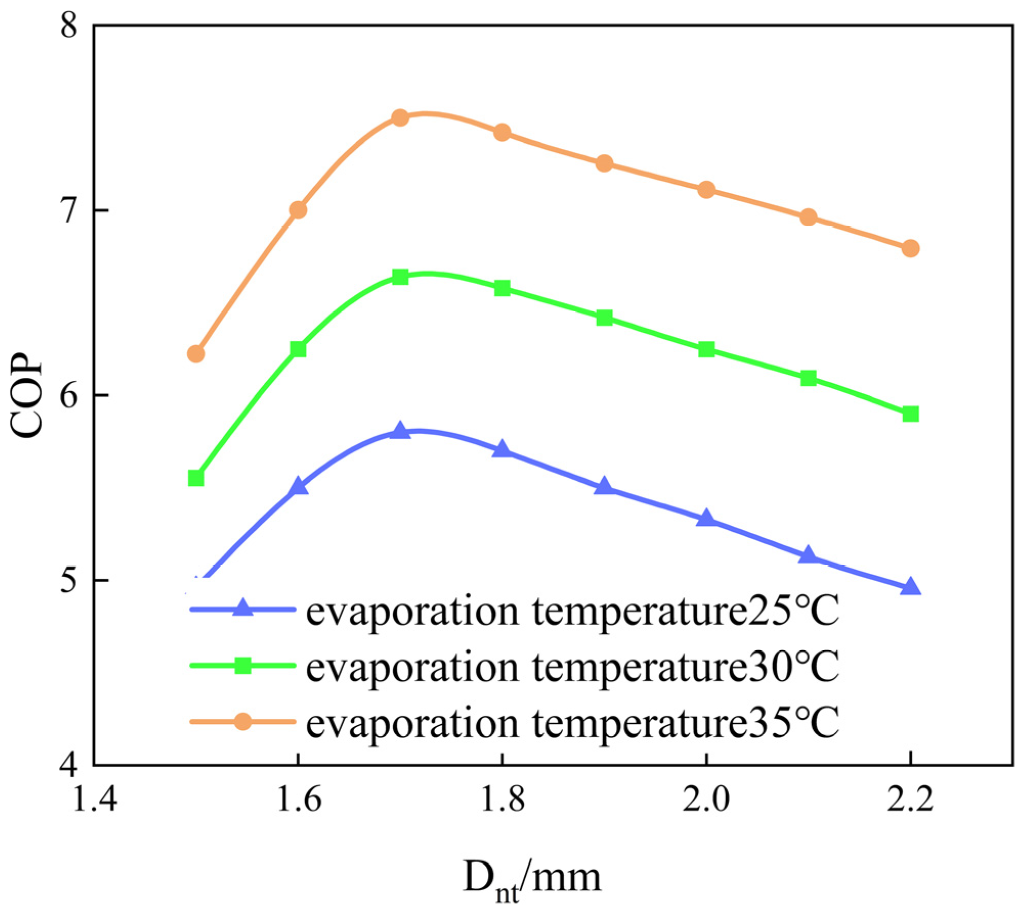
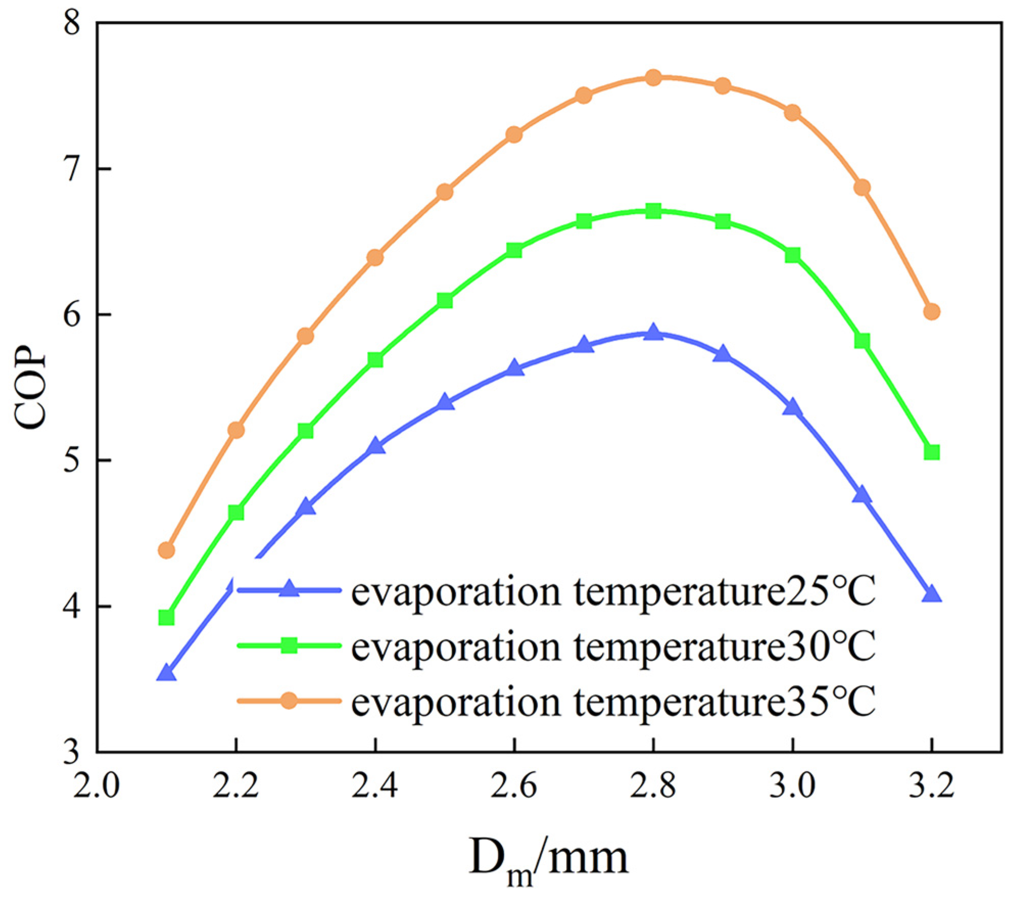
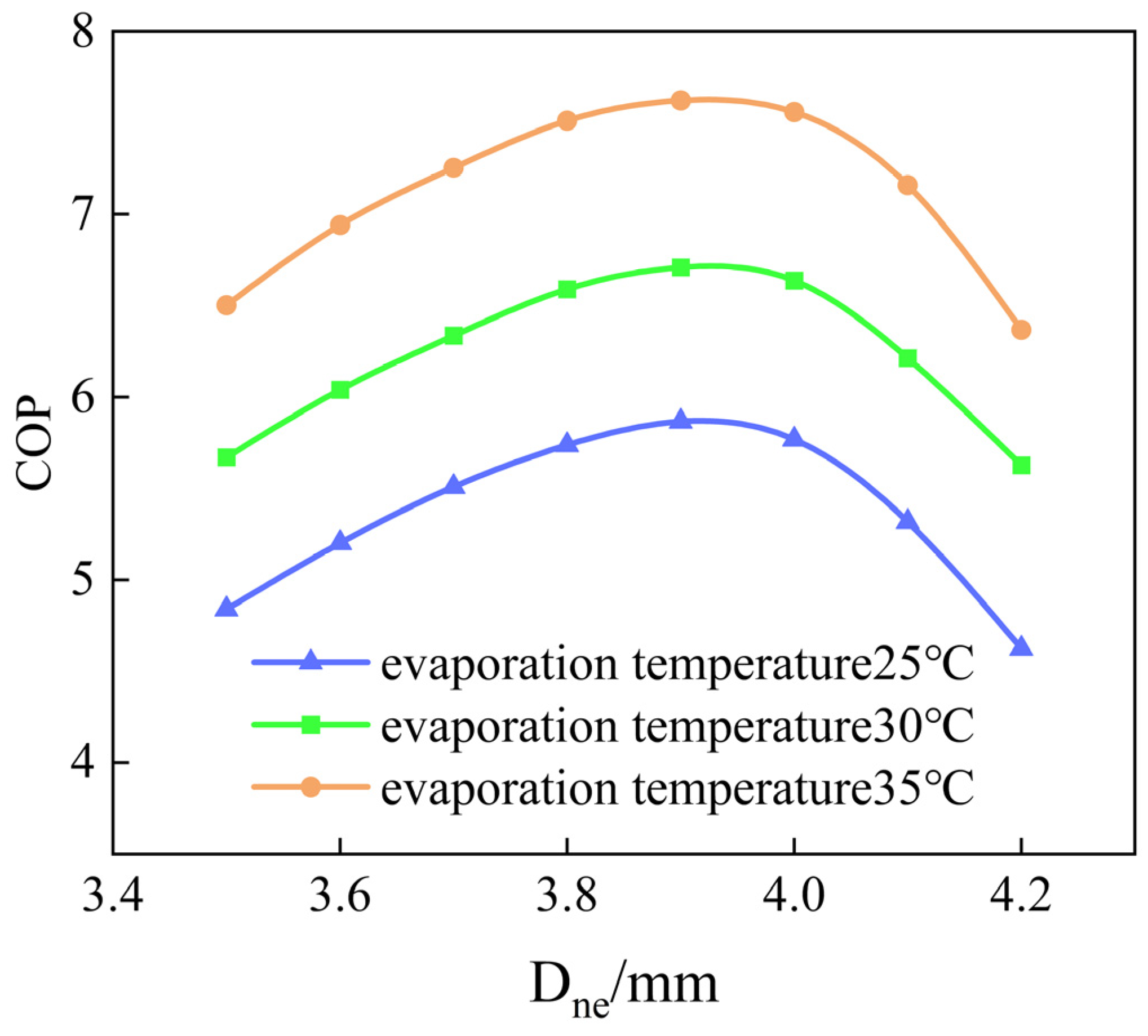
3.3. Influence of Ejector Parameters on System Performance
- Design parameters
- Comparison of nozzle structural parameters and their impact on system COP
4. Conclusions
- (1)
- The average temperature range of available waste heat of a certain type of converter valve during a certain year is between 30 and 47 °C, and the capacity level is between 35,000 and 5500 kW; This low-grade high-capacity heat source is upgraded to a heat source of 70–90 °C through heat pump technology, which is applied in fields such as refrigeration, heating, seawater desalination technology, and sewage treatment.
- (2)
- Under the calculation conditions set in this article, thermal analysis was conducted on the BVCHPS and EEHPS. The results showed that selecting five refrigeration refrigerants (R515b, R515a, R134a, R1234yf, and R1234ze) for analysis showed that the EEHPS can effectively improve the system COP. In addition, the exergy efficiency analyzed with R515b as a representative can be improved by about 8%.
- (3)
- The analysis of the structural parameters of the ejector shows that the nozzle throat diameter, mixing chamber diameter, and nozzle outlet diameter of the ejector have an impact on the COP of the EEHPS, and there is an optimal diameter size available. Subsequent work will carry out optimization design and experimental testing.
- (4)
- The research group will further carry out the construction of the BVCHPS and EEHPS experimental platforms to verify the accuracy of the theoretical analysis results in this paper.
Author Contributions
Funding
Data Availability Statement
Conflicts of Interest
References
- Zhou, J.H.; Zhang, X.J.; Hou, J.Y.; Wang, H.; Yang, H. A New Converter Valve Cooling System Based on Residual Heat Recovery. South. Power Syst. Technol. 2019, 13, 16–23. (In Chinese) [Google Scholar] [CrossRef]
- Yang, L.; Zhang, L.; Zhou, Y.B.; Hou, T.; Xu, S.K. Integrated Design Scheme of External Cooling System of VSC-HVDC Converter Valve and Water-Cooled Transformer. South. Power Syst. Technol. 2021, 15, 15–19. (In Chinese) [Google Scholar] [CrossRef]
- Kim, M.-H.; Pettersen, J.; Bullard, C.W. Fundamental process and system design issues in CO2 vapor compression systems. Prog. Energy Combust. Sci. 2004, 30, 119–174. [Google Scholar] [CrossRef]
- Elbel, S.; Lawrence, N. Review of recent developments in advanced ejector technology. Int. J. Refrig. 2016, 62, 1–18. [Google Scholar] [CrossRef]
- Harrell, G.S.; Kornhauser, A.A. Performance tests of a two-phase ejector. In Proceedings of the 30th Intersociety Energy Conversion Engineering Conference, Orlando, FL, USA, 30 July–4 August 1995; pp. 49–53. [Google Scholar]
- Zhang, Z.Y.; Feng, X.; Tian, D.Z.; Yang, J.; Chang, L. Progress in ejector-expansion vapor compression refrigeration and heat pump systems. Energy Convers. Manag. 2020, 207, 112529. [Google Scholar] [CrossRef]
- Chua, K.J.; Chou, S.K.; Yang, W.M. Advances in heat pump systems: A review. Appl. Energy 2010, 87, 3611–3624. [Google Scholar] [CrossRef]
- Gagan, J.; S’mierciew, K.; Butrymowicz, D. Performance of ejection refrigeration system operating with R-1234ze(E) driven by ultra-low grade heat source. Int. J. Refrig. 2018, 88, 458–471. [Google Scholar] [CrossRef]
- Li, S.Y.; Lu, J.; Li, W.Y.; Huang, S.; Tian, L. Comparative performance of ternary azeotropic mixtures as substitutes for R134a in dual-temperature air source heat pump combined ejector. Therm. Sci. Eng. Prog. 2023, 37, 101577. [Google Scholar] [CrossRef]
- Zou, L.G.; Liu, Y.; Yu, J.L. Energy, exergy and economic evaluation of a solar enhanced ejector expansion heat pump cycle. Renew. Energy 2023, 217, 119119. [Google Scholar] [CrossRef]
- Zhao, Y.; Yu, J.L. Thermodynamic analysis of a modified vapor-injection heat pump cycle using an ejector. Int. J. Refrig. 2023, 145, 137–147. [Google Scholar] [CrossRef]
- Al-Sayyab, A.K.S.; Navarro-Esbrí, J.; Mota-Babiloni, A. Energy, exergy, and environmental (3E) analysis of a compound ejector-heat pump with low GWP refrigerants for simultaneous data center cooling and district heating. Int. J. Refrig. 2022, 133, 61–72. [Google Scholar] [CrossRef]
- Wang, X.; Yu, J.L.; Xing, M.B. Performance analysis of a new ejector enhanced vapor injection heat pump cycle. Energy Convers. Manag. 2015, 100, 242–248. [Google Scholar] [CrossRef]
- Liu, F.; Groll, A.E. Study of ejector efficiencies in refrigeration cycles. Appl. Therm. Eng. 2013, 52, 360–370. [Google Scholar] [CrossRef]
- Li, H.S.; Cao, F.; Bu, X.B.; Wang, L.; Wang, X. Performance characteristics of R1234yf ejector-expansion refrigeration cycle. Appl. Energy 2014, 121, 96–103. [Google Scholar] [CrossRef]
- Mastrowski, M.; Smolka, J.; Butrymowicz, D.; Antczak, Ł.; Gagan, J.; Śmierciew, K. Experimental validation of the theoretical ejector model in a low-grade waste heat refrigeration system using R1233zdE as a working fluid. Appl. Therm. Eng. 2024, 236, 121716. [Google Scholar] [CrossRef]
- Bilir, S.N.; ERsoy, H.K. Experimental investigation on motive nozzle throat diameter for an ejector expansion refrigeration system. Energy Convers. Manag. 2016, 124, 1–12. [Google Scholar] [CrossRef]
- Dincer, I.; Rosen, M.A. Thermal Energy Storage: Systems and Applications; John Wiley & Sons: Hoboken, NJ, USA, 2010. [Google Scholar]
- Zhu, G.Q. A Study on the Performance of Air Source Heat Pump Based on Two-Phase Ejector Boosting Pressure. Master’s Thesis, Taiyuan University of Technology, Taiyuan, China, 2017. (In Chinese). [Google Scholar]


| Refrigerant | Condensation Temperatures Ranging/°C | Evaporation Temperature/°C | Throat Diameter (Dnt)/mm | Nozzle Outlet Diameter (Dne)/mm | Mixing Chamber Diameter (Dm)/mm |
|---|---|---|---|---|---|
| R134a | 30, 35, 40, 45, 50, 55 | 5 | 2 | 2.7 | 6.64 |
| Refrigerant | R515b | R515a | R134a | R1234yf | R1234ze |
|---|---|---|---|---|---|
| Molar mass (g/mol) | 117.5 | 118.7 | 102.03 | 94.7 | 114.04 |
| Boiling point/°C | −19 | −19 | −26.2 | −29.5 | −18.95 |
| Critical temperature/°C | 108.7 | 108.7 | 101.1 | 95 | 109.4 |
| GWP | 299 | 403 | 1300 | 4 | 4 |
| ODP | 0 | 0 | 0 | 0 | 0 |
| Flammability | Non-flammability | Non-flammability | Non-flammability | Low flammability | Flammability |
| Toxicity | Non-toxicity | Non-toxicity | Non-toxicity | Low toxicity | Low toxicity |
| Components | Exergy Loss (kW) | Exergy Loss Coefficient (%) | ||
|---|---|---|---|---|
| R134a | R515b | R134a | R515b | |
| Compressor | 2.29 | 2.13 | 15.26 | 14.2 |
| Condenser | 4.25 | 3.95 | 28.33 | 26.33 |
| Ejectors | 3.52 | 3.27 | 23.46 | 21.8 |
| Gas–liquid separator | 0.02 | 0.02 | 0.13 | 0.12 |
| Throttle | 0.36 | 0.33 | 2.4 | 2.2 |
| Evaporator | 2.59 | 2.4 | 17.26 | 16 |
Disclaimer/Publisher’s Note: The statements, opinions and data contained in all publications are solely those of the individual author(s) and contributor(s) and not of MDPI and/or the editor(s). MDPI and/or the editor(s) disclaim responsibility for any injury to people or property resulting from any ideas, methods, instructions or products referred to in the content. |
© 2024 by the authors. Licensee MDPI, Basel, Switzerland. This article is an open access article distributed under the terms and conditions of the Creative Commons Attribution (CC BY) license (https://creativecommons.org/licenses/by/4.0/).
Share and Cite
Jin, M.; Zhang, X.; Zhou, J.; Zhang, L. Performance Analysis of an Ejector-Enhanced Heat Pump System for Low-Temperature Waste Heat Recovery Using UHVDC Converter Valves. Energies 2024, 17, 3589. https://doi.org/10.3390/en17143589
Jin M, Zhang X, Zhou J, Zhang L. Performance Analysis of an Ejector-Enhanced Heat Pump System for Low-Temperature Waste Heat Recovery Using UHVDC Converter Valves. Energies. 2024; 17(14):3589. https://doi.org/10.3390/en17143589
Chicago/Turabian StyleJin, Menghan, Xingjuan Zhang, Jianhui Zhou, and Limin Zhang. 2024. "Performance Analysis of an Ejector-Enhanced Heat Pump System for Low-Temperature Waste Heat Recovery Using UHVDC Converter Valves" Energies 17, no. 14: 3589. https://doi.org/10.3390/en17143589
APA StyleJin, M., Zhang, X., Zhou, J., & Zhang, L. (2024). Performance Analysis of an Ejector-Enhanced Heat Pump System for Low-Temperature Waste Heat Recovery Using UHVDC Converter Valves. Energies, 17(14), 3589. https://doi.org/10.3390/en17143589