Article

Study on Leakage and Diffusion Behavior of Liquid CO2 Vessel in CCES

School of Mechanical Engineering, Xi’an Shiyou University, Xi’an 710065, China
*
Author to whom correspondence should be addressed.
Energies 2024, 17(15), 3613; https://doi.org/10.3390/en17153613
Submission received: 30 May 2024 / Revised: 5 July 2024 / Accepted: 16 July 2024 / Published: 23 July 2024
(This article belongs to the Special Issue Heat Transfer and Fluid Flows for Industry Applications)

Abstract

:
Numerical simulations of the leakage and diffusion behavior of liquid CO2 vessels and security analyses were conducted in this paper, based on a CO2 compression energy storage system. With isentropic choking model, the leakage of vessels under specific conditions was numerically simulated. The influence of different wind speeds on leakage in near-zone field was studied. Meanwhile, the diffusion characteristics of CO2 under three different influencing factors were investigated with the UDM (Unified Dispersion Model) diffusion model, and the diffusion ranges of certain concentrations were detected in the far-zone field. The results show that the low-temperature zone of the 50 mm leak aperture can reach 0.74 m downwind, and basically does not change with wind speed. In the leakage direction, the maximum damage zone of high-speed flow can reach 7.70 m. For the far-zone field, the diffusion area and downwind distance of a dangerous concentration decrease with the increasing of wind speed, and the hazardous area of the low concentration is greatly affected. Based on specific conditions, the maximum diffusion area is 78.46 m2 at 1 m/s wind speed, and the dangerous range reaches 36.32 m downwind. The larger the leakage aperture, the faster the growth trend of the low concentration area under the same conditions. As the equivalent radius of the leakage aperture is less than 50 mm, the maximum diffusion area is proportional to the cubic of the leakage aperture radius. The higher the height of the leakage source, the smaller the concentration range at 1.5 m, which is the average human breathing height. The overall cloud moves upward, meaning that the ground risk decreases. When the leakage aperture is 50 mm and the wind speed is 1 m/s, the maximum cloud diffusion range is 857.35 m2 at the leakage height of 2 m, and the dangerous range reaches 109.53 m downwind, where the maximum concentration is 14.65%.

1. Introduction

Compressed CO2 energy storage (CCES) is a promising energy storage system (ESS) technology [1,2], with high reliability and low cost. The basic principle is that in the low period of electricity consumption, the excess power is used to compress carbon dioxide gas at normal temperatures and pressure it into a liquid, and the heat generated in the compression process is stored. During peak power consumption, the stored heat energy is used to heat liquid carbon dioxide into gas, driving turbines to generate electricity. Its workflow is shown in Figure 1. Through evaporators, compressors, turbines, condensers and other equipment in the cycle, the working fluid is used to store energy and release energy [3]. However, the storage and transportation of CO2 also bring about potential safety hazards, especially in the case of leakage, which may cause serious accidents [4,5]. In 1986, the “silent” CO2 trapped at the bottom of Lake Halonios suddenly erupted, suffocating more than 1700 residents and a large number of animals [6]. On the evening of 30 May 2019, a CO2 leakage accident occurred on a cargo ship in Rongcheng, Shandong Province, resulting in more than 30 casualties [7]. Therefore, it is necessary to research the leakage diffusion of CO2 vessels.
CO2 is generally stored in specialized pressure vessels in a CCES, which is a liquid fluid at high pressure. Due to improper human operation, the aging of components, corrosion, etc. [8], there is a possibility of vessel leakage and the creation of an area of asphyxiation [9,10]. According to the National Institute for Occupational Safety and Health, when the concentration of CO2 reaches 2%, a person will have difficulty in breathing in a few hours; when the concentration of CO2 reaches 4%, it will endanger persons in half an hour; and when the concentration of CO2 reaches 6%, it will cause death in a few minutes [11]. Therefore, specific concentrations of carbon dioxide during vessel leakage are matters of concern.
In recent years, scholars have mainly focused on diffusion leakage from CO2 pipelines. Diffusions of pure CO2 or CO2 containing impurities were experimentally investigated during the leakage of high-pressure CO2 pipelines. The temperature evolution and the motion of dry ice particles in the far field were brought into focus [12,13,14,15]. Likewise, leakage behavior and indoor CO2 gas diffusion characteristics have been studied [16,17]. Theoretically, a calculation method used to predict the CO2 concentration was proposed [18]. Based on the numerical calculation method, a numerical model of a high-pressure CO2 leakage jet was presented, and the leakage characteristics of a ruptured high-pressure CO2 pipeline were put forward [19]. It was numerically simulated to capture the characteristics of the near-field supersonic under-expanded jet structure, expansion surge change and potential Mach disk by Li K et al. [20]. The calculated jet plume center and linear velocity change results were consistent with the experimental measurements. Tian, GY et al. investigated the release characteristics inside the vessel and the diffusion phenomena outside the rupture using high-pressure CO2 release experiments with different initial states, temperatures, and rupture sizes. High-pressure CO2 release experiments were conducted to investigate the release characteristics inside the vessel and the diffusion phenomena outside the rupture [21].
However, numerical investigations of CO2 vessel leakage are rarely involved [22]. Therefore, the diffusion characteristics and concentration distribution of the leakage are investigated in this paper, taking the liquid CO2 pressure vessel of the energy storage system as a model. They are performed with different wind speeds, leakage apertures, and leakage heights. Based on the FLUENT 2023r1 (23.1.0) and PHAST 8.4 (165.0) software, theoretical references for the safe operation of the energy storage system are provided.

2. Physical Model and Governing Equations
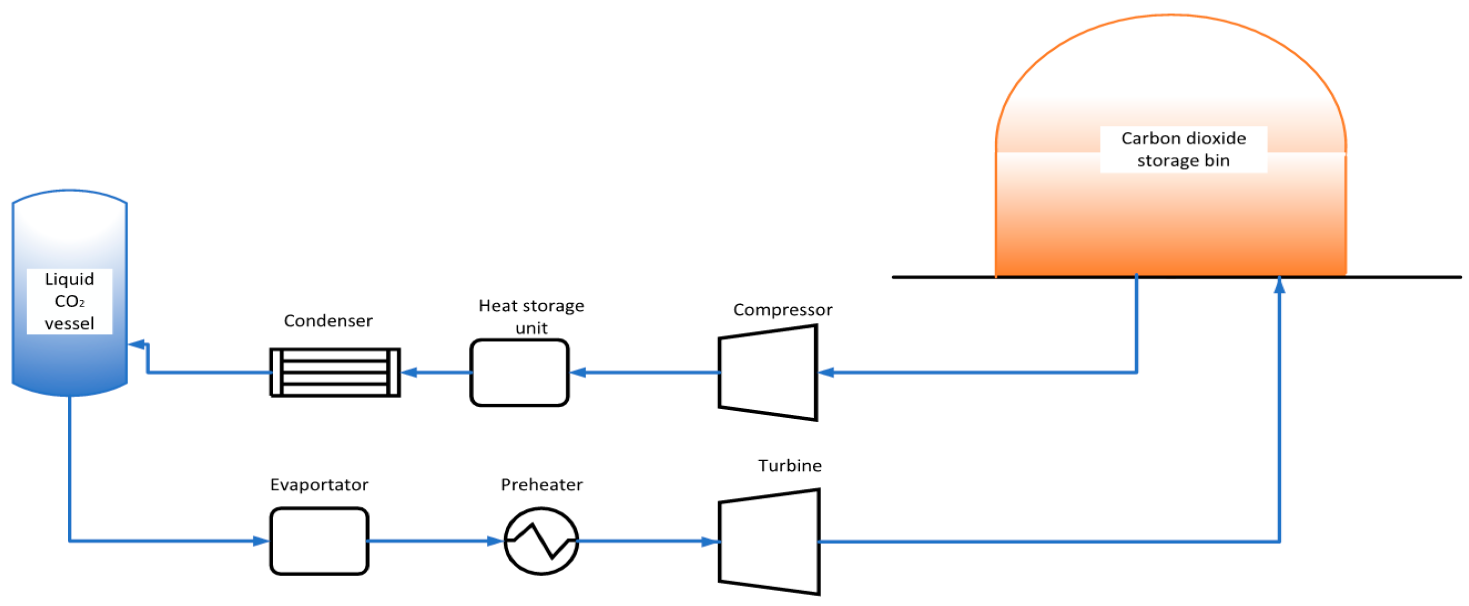
2.1. Physical Model

The vessel is 70 m3, and is equipped with 7 Mpa, 28 °C high-pressure pure liquid carbon dioxide, based on the CCES system in Deyang City, Sichuan Province. The diameter of the storage vessel is 2 m, the length is 12.2 m, the location of the vessel is 3 m from the ground, and the size of the leakage space in the simulation is 100 m × 200 m × 100 m.
The physical model of the vessel is shown in Figure 2.
In the near-zone of the leaking, the liquid carbon dioxide escapes from the aperture with simultaneous pressure and temperature drops, causing rapid phase transition in the near-zone field. As the triple point of pure carbon dioxide is −56.6 °C and 0.518 MPa, carbon dioxide may coexist as a gas, liquid and solid.
Due to the fast phase transition rate and the small three-state coexistence region, it still follows the law of compressible gas flow. Choking flow occurs at the leak outlet, because the back pressure is much lower than the stagnation pressure of compressible fluid in the vessel. The flow velocity and pressure before the sound velocity section (at the leakage aperture) no longer change with back pressure. For the far-zone of the leak, fluid flow and diffusion are the processes of heat and mass transfer. The distribution of concentrations is of particular concern.

2.2. Flow Equations

As carbon dioxide leaks from the vessel, the fluid motion follows the continuity equation, the motion equation, the energy equation, and the P-R equation of state chosen for calculating the change in the physical parameters [23]. The expressions of each equation are as follows.
(1)
Continuity equation:=
ρ t + ( ρ V ) = 0
where ρ is the fluid density, kg/m3; t is the time, s, and V is the velocity tensor.
(2)
Equation of motion
ρ D V D t = ρ f + P
where D D t = t + ( V ) is the follower derivative; f is the mass force tensor; P is the stress tensor with the expression P = p I + 2 μ ( E 1 3 V I ) ; E is the strain rate tensor of the fluid; I is the unit tensor, and μ is the coefficient of dynamic viscosity.
(3)
Energy equation
ρ c V D T D t = ρ q + ( k T ) p ( V ) + Φ
where c V is the constant volume-specific heat coefficient of the fluid; T is the fluid temperature; k is the coefficient of thermal conductivity; q is related to thermal radiation or flow accompanied by combustion, chemical reactions, etc., in a unit of time, which transfers the heat per unit of mass of fluid. The viscous dissipation function is Φ = 2 μ ( E 2 1 3 ( V ) 2 ) .
(4)
Equation of state
P = R T ( V m b ) a ( V m 2 + μ b V m + ω b 2 )
a = 0.45724 R 2 T c 2 P c 2 [ 1 + ( 0.37464 + 1.54226 ω 2 ) ( 1 T T c ) ] 2
b = 0.0778 R T c P c
where the corresponding constants of the P-R equation of state are μ = 1 , ω = 2 ; a , b are substance-specific constants, related to the critical parameters; V m is the molar volume of the gas.
According to the analysis of carbon dioxide’s physical properties, Bernoulli’s theory is not applicable to the leakage process in the near-zone field. Without considering the loss, the leakage process can be reduced to an isentropic process. Based on the isentropic choking model [21],
p a p 0 ( 2 n + 1 ) n n 1
Then, the leakage fluid reaches a critical flow state at the outlet. The velocity at the leakage outlet is the local sound velocity and the Mach number is 1. Therefore, the relationship between the stagnation pressure in the vessel and the critical pressure at the leakage outlet is
p c r p = ( 2 n + 1 ) n n 1
Then, critical flow velocity at the leakage outlet is
v c r = φ 2 n n + 1 R T *
where p a ,   p 0 ,   p c r ,   p represent atmospheric pressure, vessel pressure, critical pressure and stagnation pressure, respectively. T * is the stagnation temperature. n is the adiabatic exponent of carbon dioxide. p 0 = p under these conditions.

2.3. Diffusion Equations

Due to the assumptions and the unclear phase transformation mechanism, research on far-field diffusion will produce results inconsistent with the reality when following the above model. The unsteady characteristics based on ANSYS will also consume a lot of computing time and resources. Therefore, based on the PHAST 8.4 (165.0) software of Det Norske Veritas (DNV), two sub-models of the UDM (Unified Diffusion Model) [24,25,26] are used for the numerical simulation of CO2 diffusion in the far-zone field, which are the quasi-instantaneous model and finite time correction model [27,28]. The basic equations of the UDM model [29,30] are as follows.
The UDM instantaneous release equation is
c ( x , y , ξ , t ) = c 0 ( t ) F v ( ξ ) F h ( x , y )
F h ( x , y ) = e x p { ( x x c l d ( t ) R x ( t ) ) 2 + y R y ( t ) } m 2 , ( R x = R y )
ξ = z z c l d ( t )
d x c l d d t = v x
d z c l d d t = v z z c l d m c l d d m c v a p d t
where x is the horizontal distance downwind, m; y is the crosswind distance, m; ξ is the distance from the centerline of the smoke and rain, m, which relates to the time to release forward, s; z is the vertical height above the ground, m; x c l d is the position of the horizontal center of the cloud mass downwind, m; z c l d is the height of the centerline of the cloud mass from the ground, m; v x is the component of velocity V in the x-direction and v z is the component of velocity V in the z-direction; m c v a p is the component mass evaporated from the pool, kg.
The UDM continuous release equation is
c ( x , y , ξ ) = c 0 ( x ) F v ( ξ ) F h ( y )
F v ( ξ ) = e x p { | ξ R z ( x ) | n ( x ) }
F h ( y ) = e x p { | y R y ( x ) | m ( x ) }
where c is the concentration, mol/m3; c 0 is the centerline concentration, mol/m3; F v ( ξ ) is the distribution of the concentration in the vertical direction; F h ( y ) is the distribution of the concentration in the horizontal direction; m is the index of the horizontal distribution of the concentration; n is the index of the vertical distribution of the concentration; R y is the constant value of the concentration profile of the transverse peak; R z is the constant value of the vertical concentration profile.
The INEX cloud expansion velocity V equation is
d m w a d t = ρ a A V E ,   if   z c l d R   ( cloud   elevated )   or   if   z c l d = 0   ( cloud   grounded )
d m w a d t = ρ a { A V E + A f o o t p r i n t d z c l d d t } ,   if   0 < z c l d < R   ( cloud   touching   down )
V = d R d t = V E + V D
Here, A is the surface area of the cloud above the ground (UDM equivalent S a b o v e ), and A f o o t p r i n t = π ( R 2 z c l d 2 ) is the cloud footprint area; z c l d is the centerline height; R is the cloud radius, V E is the air entrainment velocity and V D is the air displacement velocity.
Thermodynamic equilibrium equation:
H c l d = m a h a ( T ) + m w v h w v ( T ) + m w n h w n ( T ) + m c v h c v ( T ) + m c L h c L ( T d )
where the droplet temperature T d = T in case of HEM, and T d is set from the droplet energy balance in the case of the non-equilibrium model. THRM also accounts for solid effects (water ice, and CO2, pollutant currently only) and multi-component releases (assuming Raoult’s law). In the above equation, m w v is the mass of water vapor, and m w n is the mass of water non-vapor (either liquid or ice).

3. Results and Discussion

Based on ANSYS and PHAST separately, the leakage behavior in the near-zone field and the diffusion behavior in the far-zone field were studied numerically.

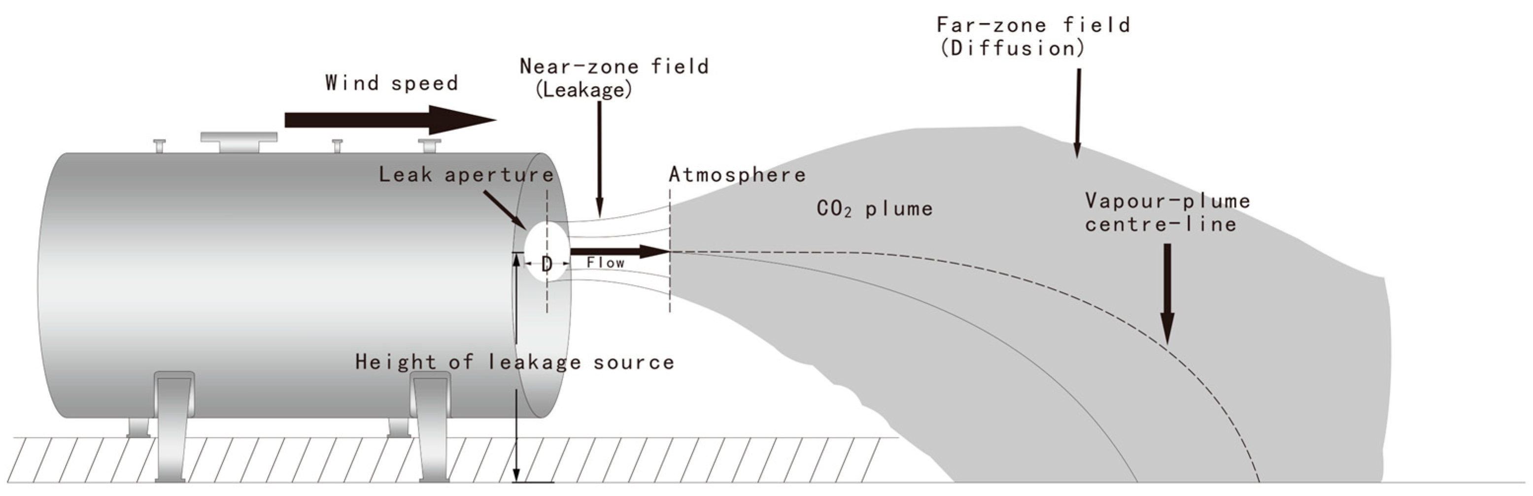
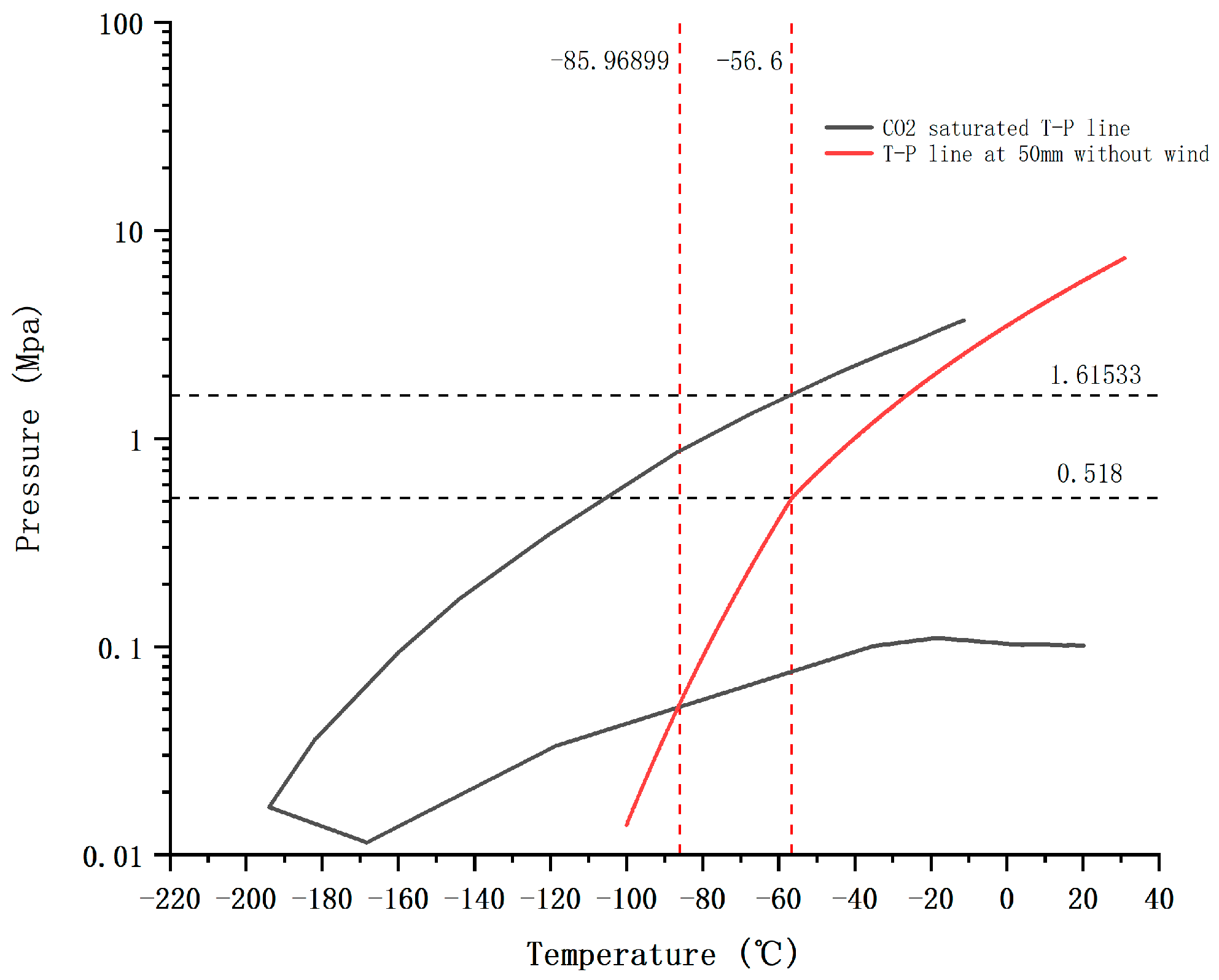
3.1. Leakage Behavior in the Near-Zone Field

The liquid carbon dioxide vessel is simplified and the mesh is divided by ANSYS. The mesh number is 294,745. Based on the numerical solution method of compressible gas, the robust k ω SST model is selected for the turbulence model, and the flow field near the leakage port is simulated by combining the transport equation and energy equation. The pressure inlet and the pressure outlet are selected, and the critical parameters are set as the flow field inlet conditions. The leakage of the 50 mm aperture is analyzed numerically based FLUENT. The leakage direction is set as upward, in order to better understand the effect of wind speed in the near field area.
Figure 3 shows the cloud pattern of dangerous concentrations (above 2% mass fraction) of carbon dioxide leakage at different wind speeds. With the increase in wind speed, the cloud pattern gradually changes from narrow and long to low and wide, which indicates that wind speed has a great influence on carbon dioxide diffusion, suggesting a strong transport capacity in gas diffusion. At the same time, it can be seen from the image that the higher the concentration, the smaller the diffusion range and the closer to the release source. Wind speed has little effect in the near-field zone of leakage. As can be seen from the Figure 4, CO2 continues to accelerate to supersonic speed due to expansion after leaving the leakage port, and its speed rapidly decreases to subsonic speed after passing through the Mach disk. However, the fluid on both sides of the leakage axis is still supersonic, which will accelerate the subsonic fluid on the leakage axis, and finally the fluid speed decreases continuously, due to enrolling the surrounding air. When the air flow speed is above 25 m/s (equivalent to Force 10 gale), it will cause a certain degree of damage to the human body and surrounding buildings. As shown in the figure, the distance in leakage direction is 7.70 m when the fluid speed reaches 25 m/s. This indicates that the wind speed has a weak influence on the near-zone field.
Figure 5 shows the T-P diagram of leakage with a 50 mm aperture in the near-zone field when it is windless, based on the assumption of no phase transition. Combined with the carbon dioxide phase diagram, it can be seen that carbon dioxide is liquid when the pressure is above 1.62 Mpa, and the temperature above −85.96 °C is gaseous. Therefore, it is concluded that the phase transition of carbon dioxide fluid occurs in the leakage direction of 0 m to 0.32 m, which is the distance to the leak port in the axial direction. At the same time, according to the analysis of the temperature field, the low-temperature danger zone (below 0 °C) of the 50 mm aperture leakage process can reach the maximum of 0.74 m in the axial direction from the leak port and 0.19 m in the radial direction, which is independent of the wind speed.

3.2. Diffusion Behavior in Far-Zone Field
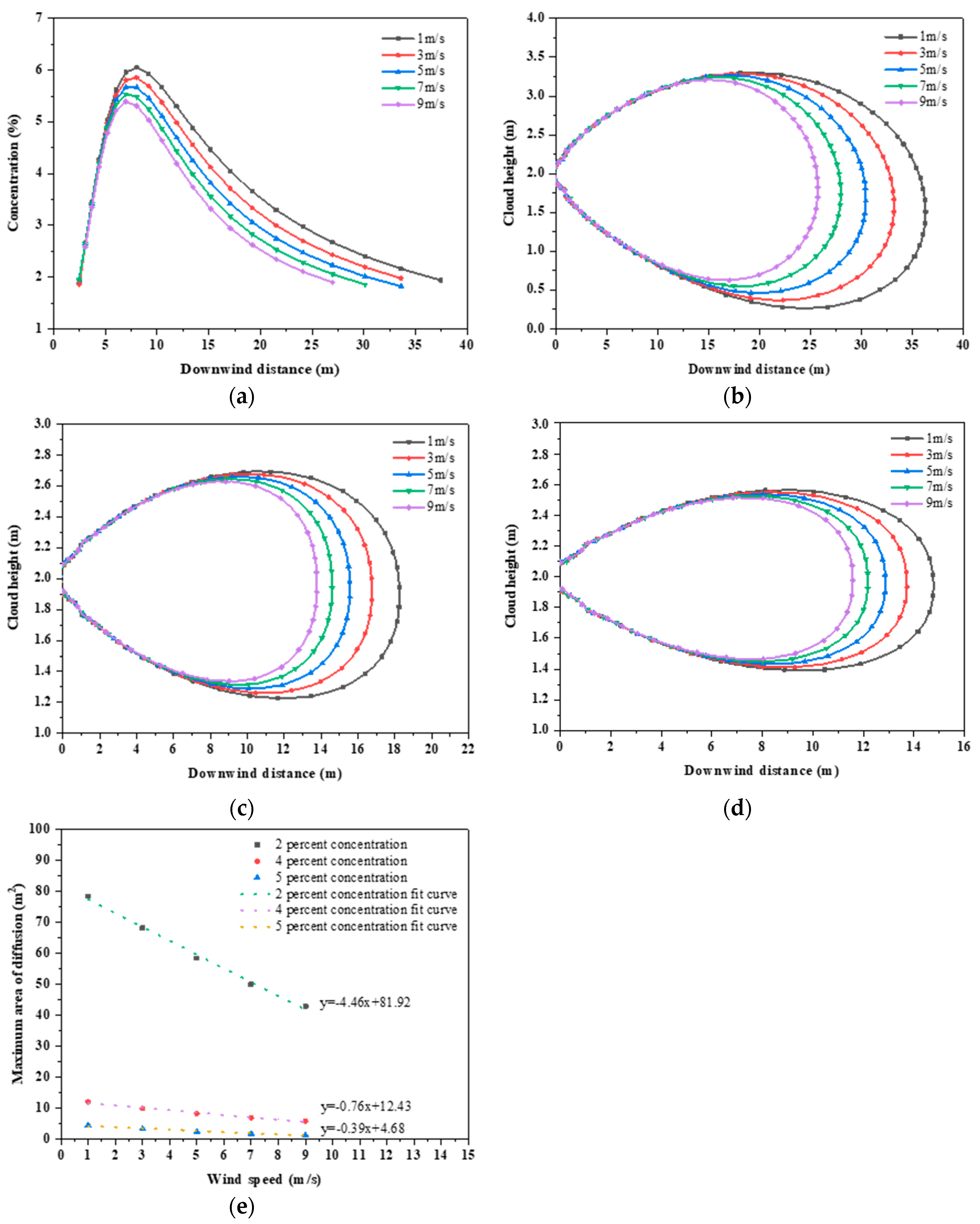
In the far-zone field, the carbon dioxide flow is mainly characterized by diffusion. The concentration distributions of carbon dioxide vessel leakage are assessed, with different wind speeds, leakage apertures or leakage heights. Carbon dioxide concentrations of 2%, 4% and 5% are remarkable. The results are shown below.

3.2.1. Wind Speed

In Section 2.2, V in Equation (1) represents the absolute velocity of the fluid, which is equal to the sum of the relative velocity (carbon dioxide velocity) and the implicit velocity (wind speed). The concentration equations of the UDM model in turn contain x c l d and z c l d , and it can be seen from Equations (13) and (14) that these values have a strong relationship with the wind speed, which has therefore been selected as the main object of study. The wind speed values selected for the study of the effect of wind speed on leakage diffusion were 1, 3, 5, 7 and 9 m/s, and other partial parameters are shown in Table 1.
The simulation results are shown in Figure 6; Figure 6a shows the concentration at the height of interest as a function of distance for different wind speeds. Figure 6b shows the concentration at the height of interest versus downwind distance for different wind speeds. Figure 6c,d shows the relationship between cloud width and downwind distance. Figure 6e shows the relationship between different wind speeds and the maximum area of cloud diffusion in the top view.
At the average breathing height of 1.5 m for humans, the concentration firstly increases and then decreases with the diffusion distance in Figure 6, showing the distribution of focused carbon dioxide concentration at different wind speeds. When the wind speed gradually increases from 1 m/s to 9 m/s, the maximum concentrations are 6.05%, 5.85%, 5.67%, 5.54%, and 5.39%, and the locations of the maximum concentration are at the downwind distance of 8.02 m, 8.02 m, 6.97 m, 6.97 m, 6.97 m, and 6.97 m, respectively, from the vessel. Under these conditions, a person will be close to unconsciousness within a few minutes at a concentration of greater than 5%. Therefore, it can be concluded that it is very dangerous in the range of 6.97~8.02 m from the leakage source. From Figure 6, it can also be concluded that the wind has a driving effect on diffusion, but at the same time will reduce the risk of diffusion. At 10.46 m downwind from the source of the leakage, the concentrations related to wind speeds of 1 m/s to 9 m/s were 5.66%, 5.38%, 5.12%, 4.87% and 4.64%, respectively.
From Figure 6b–d, it can be seen that when the leakage aperture is 20 mm and the leakage height is 2 m, the increase in wind speed reduces the aggregation effect of the carbon dioxide cloud, and the range of the hazardous area decreases. From Equation (20), we see that the wind speed affects the spreading of clouds; the diffusion distance can be up to 36.32 m at a wind speed of 1 m/s. The diffusion distances are 33.23 m, 30.45 m, 27.98 m and 25.74 m at wind speeds of 3 m/s, 5 m/s, 7 m/s and 9 m/s, respectively. The carbon dioxide is caused by gravity to sink to the area of greater concentration closer to the source, and the sinking tendency is not obvious.
In Figure 6e, we see that the wind speed is linearly inversely correlated with the top-view maximum diffusion area; the larger the wind speed, the smaller the area, and lower concentrations lead to quicker reductions, as is the case with the concentration of 2% in the cloud top-view maximum area in Table 2, which ranges from 78.46 m2 to 42.90 m2. Here, the diffusion range is reduced by 35.56 m2, while the 4% and 5% concentration areas are reduced by 6.17 m2 and 3.2 m2, respectively, which reductions are much smaller than the 42.90 m2 area. This is because the low concentration area has a large diffusion range, and its edge area is far away from the leakage source, meaning the concentration will be reduced quickly and will not be easily maintained under high wind speeds, while the high-concentration area is nearer to the leakage source, and can be continuously replenished.
According to the results obtained from the simulation, its data were processed to obtain the distribution of hazardous areas of carbon dioxide clouds under different wind speeds, as shown in Table 2. These can be disregarded because the direction of the leakage and the direction of the wind speed are both in the horizontal right direction, and the upwind diffusion is almost non-existent here.

3.2.2. Leakage Aperture

The amount of leakage per unit time depends on the leakage aperture, which has an influence on the area of distribution of the high-concentration area. The apertures of diffusion causing carbon dioxide vessel leakage are 10, 20, 30, 40 and 50 mm, and other partial parameters are shown in Table 3.
The simulation results are shown in Figure 7; Figure 7a shows the concentration at the height of concern versus the distance at different leakage apertures, Figure 7b–d shows the relationship between the width of the cloud and the distance downwind, and Figure 7e shows the relationship between different leakage apertures and the maximum area of the cloud spreading downwind.
At the average breathing height of 1.5 m, the leakage aperture increases and the concentration at the same diffusion distance is higher in Figure 7. The maximum concentrations at leakage apertures of 20, 30, 40 and 50 mm are 5.85%, 8.82%, 11.66% and 14.46%, respectively, and the locations of the maximum concentrations are 8.02, 8.02, 7.72 and 8.46 m downwind, respectively, meaning people will be unconscious or die within one minute at the maximum concentrations.
Figure 7b–d show that, as the leakage aperture increases, the diffusive side-view range of the cloud with the same concentration becomes larger. The area with a hazardous concentration at the ground level is the largest when the leakage aperture is 50 mm, with the 2% concentration’s area at ground level being 11.29 to 110.92 m, and the 4% concentration’s area at ground level being 20.47 to 43.66 m. The 5% concentration’s area does not cover the ground level, which indirectly verifies the fact that the larger the concentration is, the smaller the range is.
In Figure 7e, we see that when the leakage aperture is less than 50 mm, the maximum area of carbon dioxide cloud diffusion A is approximately proportional to the third power of D of the leakage aperture, i.e., the smaller the concentration is, the more obvious the growth trend is. When the leakage aperture is 10 mm, there are no data on the top-view area of carbon dioxide cloud diffusion, which is because the leakage aperture is too small when the height of concern is 1.5 m, resulting in less leakage within the same time, and the wind speed has a stronger weakening ability. At this time the concentration does not reach a level of concern, so there are no data on the maximal area, which is reflected in Figure 7b–d, in which the horizontal line of cloud height of 1.5 m does not intersect with any part of the diffusion map produced with a leakage aperture of 10 mm.
Based on the results obtained from the simulation, the data were processed to obtain the range of diffusion of each concentration of carbon dioxide cloud at different leakage apertures, as shown in Table 4, where upwind diffusion is also not considered.

3.2.3. Leakage Source Height

Based on Equations (16) and (17), the height of the leakage source impacts the concentration of carbon dioxide at the average breathable zone. The leakage heights related to the diffusion of carbon dioxide vessel leakage are 2, 3, 4 and 5 m in this paper. Other partial parameters are shown in Table 5.
The results of the simulation are shown in Figure 8; Figure 8a shows the concentration at the height of interest versus distance at different leakage heights, Figure 8b–d show the relationship between the width of the cloud and the distance downwind, and Figure 8e shows the relationship between the different leakage heights and the maximum area of the cloud diffusion from the top view.
When the leakage aperture is 50 mm and the wind speed is 1 m/s, in the area above the average breathable zone of 1.5 m, the height of the leakage is inversely proportional to the diffusion distance of the cloud, and the lower the height of the leakage, the greater the diffusion distance of the maximum concentration is, which is due to the fact that when the leakage is situated at a very high level, it is far from the ground and has a larger diffusion space, meaning that it cannot easily concentrate, and the concentration will be more easily reduced under the action of wind. When the height of the leak is 2 m or 3 m, the maximum concentration exceeds 4%, and people will lose consciousness after a few minutes.
Under the same conditions, the area on the ground of a 2% concentration of carbon dioxide produced from the leakage height of 2 m is 11.55 m to 109.04 m, the area on the ground of a 4% concentration is from 20.75 m to 45.53 m, and the hazardous area is not on the ground at the concentration of 5%. This is shown by Figure 8b–d, which indicates that the hazard related to the same leakage source at different leakage heights under the same conditions (including the leakage volume and leakage duration, etc.) decreases with the increase in height.
In Figure 8e, the leakage height and the top-view maximum diffusion area are linearly inversely proportional to each other in the region above the 1.5 m height of concern, and the decreasing trend in the diffusion area of the 2% concentration cloud is still obvious when compared with that of the 4% and 5% regions. When the leakage height is 2 m, the overhead maximum diffusion areas of 2%, 4% and 5% concentrations are 857.35 m2, 151.1 m2 and 87.37 m2, respectively; when the leakage height is 3 m, the overhead maximum areas of 2%, 4% and 5% concentrations are 662.49 m2, 72.84 m2 and 13.7 m2, respectively. When the leakage height is 4 m or 5 m, the maximum area of the 2% concentration is 476.2 m2 or 267.78 m2, which is not near to the concentration of concern. The above results show that the greater the height of the leakage port of the carbon dioxide vessel, the more the gas is affected by convective diffusion and the wind field, making the range of high carbon dioxide concentrations relatively small. Based on the results obtained from the simulation, its data can be processed to obtain the range of diffusion of each concentration of carbon dioxide cloud at different heights of the leakage source, as shown in Table 6.

4. Conclusions

In this paper, numerical simulations of the leakage and diffusion behavior of liquid CO2 vessels and security analyses were conducted, based on the CCES. The leakage characteristics in the near-zone of the leak were studied with the isentropic choking model via ANSYS, and the diffusion characteristics in the far-zone were studied with the UDM model via PHAST. The conclusions are as follows:
(1)
Based on the choking flow theory, transonic flow occurs in the near-zone of the leak. The low-temperature zone of a 50 mm leak aperture can reach 0.74 m downwind, and does not really change with wind speed. In the leakage direction, the maximum damage zone of high-speed flow can reach 7.70 m;
(2)
In the far-zone of the leak, diffusion behavior is key. The wind speed is linearly inversely proportional to the maximum diffusion area of the cloud. The high-concentration zones were concentrated at the downwind distance from 6.97 to 8.02 m, and the minimum concentration could reach up to 5.39%;
(3)
Leakage aperture has a significant effect on the diffusion of a carbon dioxide cloud. When the leakage aperture is less than 50 mm, the maximum diffusion area of the cloud is directly proportional to three times the leakage aperture. The high-concentration area is concentrated in the downwind direction at a distance of 8.02~8.46 m, and the lowest concentration reaches up to 5.85%. when the wind speed is 3 m/s, and the leakage height is 2 m, the diffusion area of the cloud is directly proportional to three times the leakage aperture with a 50 mm aperture;
(4)
In the average breathable zone of 1.5 m, there is a linear inverse relationship between the height of the leak and the maximum dispersion area. At a height of 2 m or 3 m, the maximum concentration is above 4%, which can render a person unconscious within a few minutes.

Author Contributions

Conceptualization, L.G.; Methodology, L.G.; Software, J.W.; Validation, J.W.; Formal analysis, S.W.; Investigation, S.W.; Resources, X.L.; Data curation, X.L.; Writing—original draft, B.Z.; Writing—review & editing, B.Z.; Visualization, Y.F.; Supervision, Y.F.; Project administration, Y.F.; Funding acquisition, Y.F. All authors have read and agreed to the published version of the manuscript.

Funding

This research was funded by Natural Science Basic Research Program of Shaanxi Province, grant number 2023-JC-QN-0609, and the Graduate Innovation and Practice Ability Cultivation Program of Xi’an Shiyou University, grant number YCS23114176.

Data Availability Statement

The original contributions presented in the study are included in the article, further inquiries can be directed to the corresponding author.

Conflicts of Interest

The authors declare no conflict of interest.

References

  1. Hao, J.; Yue, Y.; Zhang, J.; Yang, J.; Li, X.; Song, Y.; Zhang, Z. Research status and development prospect of carbon dioxide energy storage technology. Energy Storage Sci. Technol. 2022, 11, 3285–3296. [Google Scholar]
  2. Xu, W.; Zhao, P.; Gou, F.; Wu, W.; Liu, A.; Wang, J. A combined heating and power system based on compressed carbon dioxide energy storage with carbon capture: Exploring the technical potential. Energy Convers. Manag. 2022, 260, 1–16. [Google Scholar] [CrossRef]
  3. Zhang, Z.; Lu, Z.; Yan, L.; Wang, J.; Yao, S. Experiment and numerical investigation on flow characteristics and near-field structure of dense phase CO2 pipeline leakage. Process Saf. Environ. Prot. 2024, 182, 327–344. [Google Scholar] [CrossRef]
  4. Yin, B.; Gao, X.; Zhang, X.; Yang, S. Report of an acute carbon dioxide poisoning incident. Gems Health 2010, 1, 248. [Google Scholar]
  5. He, J.; Xiao, Y.; Huang, L.; Li, A.; Chen, Y.; Ma, Y.; Li, W.; Liu, D.; Zhan, Y. Application of leakage pre-warning system for hazardous chemical storage vessel based on YOLOv3-prePReLU algorithm. J. Loss Prev. Process Ind. 2022, 80, 104905. [Google Scholar] [CrossRef]
  6. Frith, S.; Hu, J. A suspended cloud of death over Cameroon. Gems Health 1993, 12, 31–35. [Google Scholar]
  7. Zhao, C. The Numerical Simulation on Liquid Phase Leakage and Dispersion Process of LNG Vessel. Dalian Univ. Technol. 2018, 6, 101. [Google Scholar]
  8. Zhu, G.; Cao, Q.; Wang, M.; Yu, J.; Yan, X.; Yu, S.; Liu, C. Risk analysis of diffusion of supercritical CO2 pipeline leakage. J. Saf. Environ. 2022, 22, 1486–1494. [Google Scholar]
  9. Ha, Y.-C.; Seo, J.-K.; Hwang, J.-H.X.; Ryu, S.-H. Method for Preventing Asphyxiation Accidents by a CO2 Extinguishing System on a Ship. Fire Sci. Eng. 2015, 29, 57–64. [Google Scholar] [CrossRef]
  10. Gu, S.; Li, Y.; Lin, T.; Wang, C.; Hu, Q.; Zhang, D.; Xiao, Y.; Wang, J.; Stefan, I. An experimental study on the flow characteristics during the leakage of high pressure CO2 pipelines. Process Saf. Environ. Protection 2019, 125, 92–101. [Google Scholar] [CrossRef]
  11. Chen, B.; Cui, W.; Guo, H.; Xiao, H. Influence of wind speed on leakage and diffusion characteristics of supercritical-dense phase carbon dioxide. Sci. Technol. Eng. 2019, 19, 144–149. [Google Scholar]
  12. Wang, C.; Li, Y.; Lin, T.; Gu, S.; Hu, Q.; Zhang, D.; Xiao, Y.; Wang, J. Experimental study on dispersion behavior during the leakage of high pressure CO2 pipelines. Exp. Therm. Fluid Sci. 2019, 105, 77–84. [Google Scholar] [CrossRef]
  13. Yu, S.; Yan, X.; He, Y.; Yu, J.; Chen, S. Study on the leakage morphology and temperature variations in the soil zone during large-scale buried CO2 pipeline leakage. Energy 2024, 288, 129674. [Google Scholar] [CrossRef]
  14. Liu, Z.; Xiu, Z.; Zhao, Y.; Li, M.; Li, P.; Cai, P.; Liang, Y. Experimental study on the leakage temperature field of buried CO2 pipelines. Environ. Sci. Pollut. Res. Int. 2023, 30, 70288–70302. [Google Scholar] [CrossRef]
  15. Chen, L.; Yan, X.; Hu, Y.; Yang, K.; Yu, S.; Yu, J.; Chen, S. Depressurization and heat transfer during leakage of supercritical CO2 from a pipeline. Greenh. Gases Sci. Technol. 2022, 12, 616–628. [Google Scholar] [CrossRef]
  16. Wang, Z.; Li, Y.; Tong, X.; Gong, J. Risk probability evaluation for the effect of obstacle on CO2 leakage and dispersion indoors based on uncertainty theory. J. Loss Prev. Process Ind. 2022, 74, 104652. [Google Scholar] [CrossRef]
  17. Mao, N.; Wang, Z.; Chao, Z.; Xuan, T. Qualitative and quantitative investigation on concentration of indoor dense gas caused by leakage and diffusion. Environ. Prog. Sustain. Energy 2019, 38, 424–434. [Google Scholar] [CrossRef]
  18. Hu, Y.; Yan, X.; Chen, L.; Yu, S.; Liu, C.; Yu, J. Leakage hazard distance of supercritical CO2 pipelines through experimental and numerical studies. Int. J. Greenh. Gas Control 2022, 119, 103730. [Google Scholar] [CrossRef]
  19. Kang, L.; Zhou, X.; Ran, T.; He, T.; Fang, Y.; Lin, S. Investigation of flow characteristics in small-scale highly pressurized leaked CO2 jet plume from pipeline. Int. J. Therm. Sci. 2019, 141, 160–170. [Google Scholar]
  20. Tian, G.; Yuan, Z.; Huang, Y.; Wang, J.; Wang, Y.; Zeng, C.; Huang, J. Experimental study of accidental release behavior of high-pressurized CO2 vessel. Process Saf. Environ. Prot. 2021, 145, 83–93. [Google Scholar] [CrossRef]
  21. Lu, Z.; Yan, L.; Xiao, C.; Yao, J. Numerical study of the transient behaviour of high pressure CO2 pipeline leakage. J. Saf. Environ. 2021, 21, 758–763. [Google Scholar]
  22. Wareing, C.J.; Fairweather, M.; Falle, S.A.; Woolley, R.M. Validation of a model of gas and dense phase CO2 jet releases for carbon capture and storage application. Int. J. Greenh. Gas Control. 2014, 20, 20254–20271. [Google Scholar] [CrossRef]
  23. Liu, F. Study on the Leakage and Diffusion Behavior of Supercritical Pressure CO2 from Pipelines. Master’s Thesis, Tsinghua University, Beijing, China, 2016. [Google Scholar]
  24. Marko, G.; Marco, P.; Giacomo, A.; Alessandro, T.; Romain, L. Comparison of UDM and CFD simulations of a time varying release of LPG in geometrical complex environment. J. Loss Prev. Process Ind. 2017, 44, 56–68. [Google Scholar]
  25. Shi, B.; Nie, S.; Sun, J. Research on the leakage risk of hydrogen pipelines based on dynamic Bayesian model. J. Saf. Environ. 2022, 22, 909–918. [Google Scholar]
  26. Bariha, N.; Mishra, M.I.; Srivastava, C.V. Fire and explosion hazard analysis during surface transport of liquefied petroleum gas (LPG): A case study of LPG truck vesseler accident in Kannur, Kerala, India. J. Loss Prev. Process Ind. 2016, 40, 449–460. [Google Scholar] [CrossRef]
  27. Wang, J.; Zhang, M.; Huang, X.; Chen, J. Scenario analysis of road transport accidents involving flammable and explosive hazardous chemicals. China Saf. Sci. J. 2019, 29, 172–176. [Google Scholar]
  28. Sun, B.; Zhang, H.; Lü, S.; Chen, W. Numerical Simulation of Validation and Influence Factors of Explosion Accident Caused from LPG Vessel Leakage. Trans. Beijing Inst. Technol. 2021, 41, 137–142. [Google Scholar]
  29. Brzezinska, D.; Markowski, S.A. Experimental investigation and CFD modelling of the internal car park environment in case of accidental LPG release. Process Saf. Environ. Prot. 2016, 110, 5–14. [Google Scholar] [CrossRef]
  30. Zhao, G. An easy method to design gas/vapor relief system with rupture disk. J. Loss Prev. Process Ind. 2015, 35, 321–328. [Google Scholar] [CrossRef]
Figure 1. CCES system flow schematic diagram.
Energies 17 03613 g001
Figure 2. Leakage dispersion modeling for CO2 vessel.
Energies 17 03613 g002
Figure 3. Asphyxiation concentration cloud image at different wind speeds. (a) Asphyxiation concentration cloud image at 0 m/s wind speed; (b) asphyxiation concentration cloud image at 1 m/s wind speed; (c) asphyxiation concentration cloud image at 5 m/s wind speed; (d) asphyxiation concentration cloud image at 9 m/s wind speed.
Energies 17 03613 g003
Figure 4. Velocity distribution along the leakage direction at different wind speeds.
Energies 17 03613 g004
Figure 5. T-P distribution in leakage direction at 0 m/s wind speed.
Energies 17 03613 g005
Figure 6. Distribution of focused carbon dioxide concentration at different wind speeds. (a) The diffusion distance corresponding to the concentration at a height of 1.5 m. (b) Side view of cloud diffusion with 2% CO2 concentration. (c) Side view of cloud diffusion with 4% CO2 concentration. (d) Side view of cloud diffusion with 5% CO2 concentration. (e) The maximum area of CO2 diffusion overlooking different wind speeds.
Energies 17 03613 g006
Figure 7. Distribution of carbon dioxide diffusion concentration at different leakage apertures. (a) The diffusion distance corresponding to the concentration at a height of 1.5 m under different leakage apertures. (b) Side view of cloud diffusion with 2% CO2 concentration. (c) Side view of cloud diffusion with 4% CO2 concentration. (d) Side view of cloud diffusion with 5% CO2 concentration. (e) Maximum area of CO2 diffusion under different leakage apertures.
Energies 17 03613 g007aEnergies 17 03613 g007b
Figure 8. Distribution of diffuse carbon dioxide concentrations at different leak source heights. (a) The diffusion distance corresponding to the concentration at a height of 1.5 m under different leakage heights. (b) Side view of cloud diffusion with 2% CO2 concentration. (c) Side view of cloud diffusion with 4% CO2 concentration. (d) Side view of cloud diffusion with 5% CO2 concentration. (e) Maximum area of CO2 diffusion overlooking different leakage heights.
Energies 17 03613 g008aEnergies 17 03613 g008b
Table 1. Related parameter settings.
Wind speed (m/s)13579
Height of leakage source (m)2
Leakage aperture (mm)20
Atmospheric Stability ScaleF
High level of concern (m)1.5
Table 2. Diffusion range of carbon dioxide cloud.
Wind Speed
(m/s)
2% Concentration Area4% Concentration Area5% Concentration Area
Downwind
(m)
Height (m)Maximum Area Overlooking (m2)Downwind (m)Height (m)Maximum Area Overlooking (m2)Downwind (m)Height (m)Maximum Area Overlooking (m2)
136.323.378.4618.252.6912.0414.782.564.47
333.233.2968.216.762.689.9113.722.553.38
530.453.2758.3915.562.668.2412.872.542.52
727.983.2450.0114.602.656.9412.172.531.84
925.743.2142.9013.782.635.8711.582.511.27
Table 3. Associated parameter configurations.
Leakage Aperture (mm)Height of Leakage Source (m)Wind Speed (m/s)Atmospheric Stability ScaleHigh Level of Concern (m)
1023F1.5
2023F1.5
3023F1.5
4023F1.5
5023F1.5
Table 4. Spatial extent of carbon dioxide.
Leakage Aperture (mm)2% Concentration Area4% Concentration Area5% Concentration Area
Downwind (m)Height (m)Maximum Area Overlooking (m2)Downwind (m)Height (m)Maximum Area Overlooking (m2)Downwind (m)Height (m)Maximum Area Overlooking (m2)
1014.162.626.928.232.34-6.842.28-
2033.233.2968.2016.762.689.9113.722.553.38
3057.294.06216.0426.733.0436.6621.272.8319.87
4083.914.87480.0638.393.4681.329.893.1445.84
50111.665.63878.2951.043.97146.7539.463.5083.46
Table 5. Interconnected parameter setups.
Height of Leakage Source (m)Leakage Aperture (mm)Wind Speed (m/s)Atmospheric Stability ScaleHigh Level of Concern (m)
2501F1.5
3501F1.5
4501F1.5
5501F1.5
Table 6. Carbon dioxide plume diffusion area.
Height of Leakage Source (m)2% Concentration Area4% Concentration Area5% Concentration Area
Downwind (m)Height (m)Maximum Area Overlooking (m2)Downwind (m)Height (m)Maximum Area Overlooking (m2)Downwind (m)Height (m)Maximum Area Overlooking (m2)
2109.535.74857.3552.043.97151.140.673.5187.37
399.126.06662.4948.064.6772.8438.154.3613.7
492.56.75476.246.055.61-37.035.33-
587.907.64267.7844.836.58-36.436.31-
Disclaimer/Publisher’s Note: The statements, opinions and data contained in all publications are solely those of the individual author(s) and contributor(s) and not of MDPI and/or the editor(s). MDPI and/or the editor(s) disclaim responsibility for any injury to people or property resulting from any ideas, methods, instructions or products referred to in the content.

