Article

Grid-Forming Control for Solar Generation System with Battery Energy Storage

1
State Grid Liaoning Electric Power Co., Ltd., Electric Power Science Research Institute, Shenyang 110006, China
2
School of Electrical and Information Engineering, Tianjin University, Tianjin 300072, China
*
Author to whom correspondence should be addressed.
Energies 2024, 17(15), 3642; https://doi.org/10.3390/en17153642
Submission received: 15 May 2024 / Revised: 13 July 2024 / Accepted: 15 July 2024 / Published: 24 July 2024
(This article belongs to the Special Issue Advanced Power Electronics Technology)

Abstract

:
Solar generation systems with battery energy storage have become a research hotspot in recent years. This paper proposes a grid-forming control for such a system. The inverter control consists of the inner dq-axis current control, the dq-axis voltage control, the phase-locked loop (PLL) based frequency control, and the DC voltage control. The proposed control embeds the PLL into the grid-forming inverter control, offering the advantages of better synchronization and fault current-limiting capability. With the proposed control, the battery energy storage is able to provide inertial and primary frequency support during the grid frequency disturbance. Simulation models are established in PSCAD/EMTDC, and the results during the active power variation and AC voltage variation, the grid frequency disturbance, grid fault, and mode switch validate the effectiveness of the proposed control.

1. Introduction

The use of fossil energy sources and air pollution issues drive the fast development of renewable energy. Among all the renewable energy sources, wind power generation and solar generation are the most attractive ones. In the US, wind generation accounts for 10% of the total electrical generation while solar generation will take up 5% of the total electrical generation by the end of 2023. China has set the goal that before 2030 carbon emissions will reach their peak value and before 2060 carbon neutrality will be achieved. By the first quarter of 2023, solar generation in China will exceed 228 GW while wind generation in China will exceed 310 GW. It has been reported that China is now the leader in renewable energy installation capacity worldwide and holds around 50% of the total wind and solar capacity.
However, the high penetration of renewable energy sources raises some concerns about power system stability. For the wind and solar energy sources, they are all connected to the power grid through power-electronic converters. These converters generally cannot provide the same inertial or damping as the traditional synchronous generators. In [1,2], the grid-connected converters for renewable generation sources are classified as grid-following converters and grid-forming converters.
Among the renewable generation sources in commission, they generally operate on the grid-following mode [3]. However, with the increased integration of the grid-following renewable generation sources and the decrease in the grid strength, the converter-driven oscillation becomes a serious and annoying issue. In [4], a small signal state space model is established for VSC-HVDC, and eigenvalue results show that the maximum power generated is significantly affected by the PLL and the system finds it difficult to maintain stability when the short circuit ratio is smaller than 1.3. Based on the work in [4], the authors of [5,6] establish the small signal model for doubly fed induction generator (DFIG)-based wind turbines and fully rated converter-based wind turbines, finding that the PLL and rotor-side converter power control has a noticeable effect on the DFIG connected system stability, while the weak grid, high wind power export, low voltage, and low PLL bandwidth are the main causes for the stability issues in the latter system. In [7], the harmonic state–space model considering the PLL under the asymmetrical grid is established and it is observed that the stability region of the system is reduced during the increase in the impedance asymmetrical index. In [8,9], an impedance model is built, and a generalized Nyquist plot is used to determine the system stability. It is observed that the negative resistor characteristic of qq impedance, which is mainly caused by the PLL, reduces the system stability margin. In [10], an improved feedforward control method considering PLL dynamics is proposed to improve the stability of the grid-following converter connected to a weak grid. In [11], a current error-based compensation control is proposed, where a magnitude compensation is implemented with a proportional controller whose input is the reactive current, and an angle compensation is realized with a proportional and integral (PI) controller whose input is the active current. Both eigenvalues and simulation results show the above control increases the system stability, especially when the short circuit ratio of the system is small. In [12], another advanced vector control is proposed for the grid-following converter, where the error between the active power reference and the measured one is not only the input of the active power PI controller but also the input of the reactive power PI controller. Such a control improves the system stability but suffers from the multi-parameter tuning.
An alternative way to increase the system’s small signal stability is to change the grid-following control to the grid-forming control. In [13,14], a power synchronization control is proposed using the internal synchronization mechanism in AC systems and tries to emulate a synchronous machine with the converter and the results show that the control enables the converter to provide a strong voltage support to the weak grid. In [15,16], the virtual synchronous generator and droop control-based grid-forming converter are compared, and the results show the virtual synchronous generator has larger inertia than the droop control, but when a proper lead–lag component is embedded in the active power droop control, the same small signal model has been derived with the virtual synchronous generator model. In [17,18], the sequence impedance model of the virtual synchronous generator is provided, and the stability analysis of the voltage-controlled virtual synchronous generator is compared to the current-controlled virtual synchronous generator. It is concluded that the voltage-controlled virtual synchronous generator is more similar to the traditional synchronous generator and is more stable under a weak grid when compared with the current-controlled virtual synchronous generator. In [19,20], the inertial support and primary frequency support from different types of the grid-forming converter are compared, and the simplified virtual synchronous compensator shows the advantage of providing frequency support and damping during the active power change and frequency variation.
In all, current research focuses on the control and stability analysis of the grid-forming converters without the PLL, and the synchronization is implemented through the power control during the power generation mode. But the reality is that the PLL still plays a key role for the grid-forming converter. The main reasons are as follows: (1) when the offline renewable generation sources try to connect to the grid, the phase of the grid needs to be known for smooth connection; (2) when a fault happens, the current limiting control needs a PLL. Thus, in this paper, a grid-forming control with a reserved PLL is proposed for the converters for solar generation.
The rest of this paper is organized as follows. Section 2 describes the topology of the solar generation. Section 3 presents the proposed grid-forming control for the solar generation converter. Section 4 presents the simulation under the power and voltage variation, during the grid frequency change, AC fault, and the mode switch from the grid-connected mode to the islanded mode. Finally, Section 5 draws the conclusion.

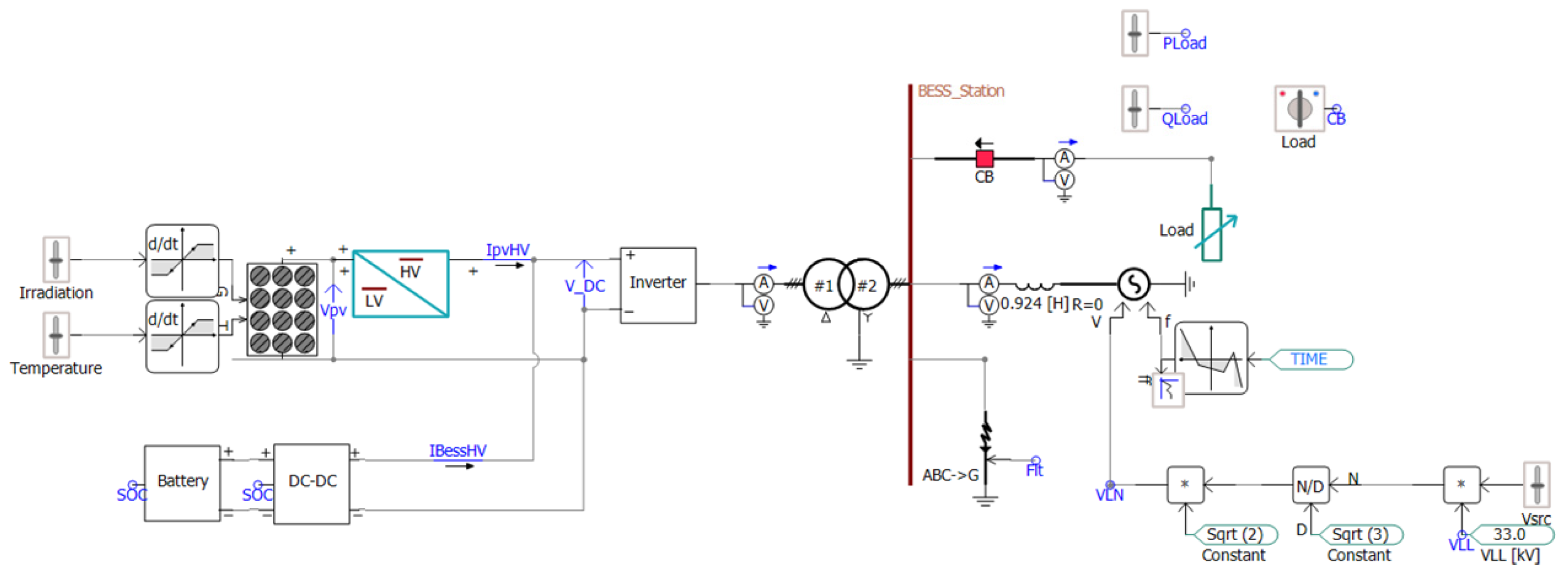
2. Topology of the Studied System

Figure 1 shows the studied grid-connected solar generation, which mainly consists of the following parts: (1) a photovoltaic (PV) array; (2) a front boost converter; (3) a battery energy storage system (BESS); and (4) an inverter. The PV array transforms the solar energy to the electricity, the DC power is injected to the front boost converter, the battery is connected to the DC bus through a bidirectional DC/DC converter, the DC power collected from both the PV and the BESS is then converted to AC power through the grid-connected inverter. The AC voltage at the inverter terminal is filtered by the LC circuit and is increased to a collection level through the transformer.

3. Proposed Grid-Forming Control for Solar Generation

This section presents the control of the solar generation, mainly includes the control of the front boost converter, control of the BESS, and the proposed grid-forming control of the inverter.

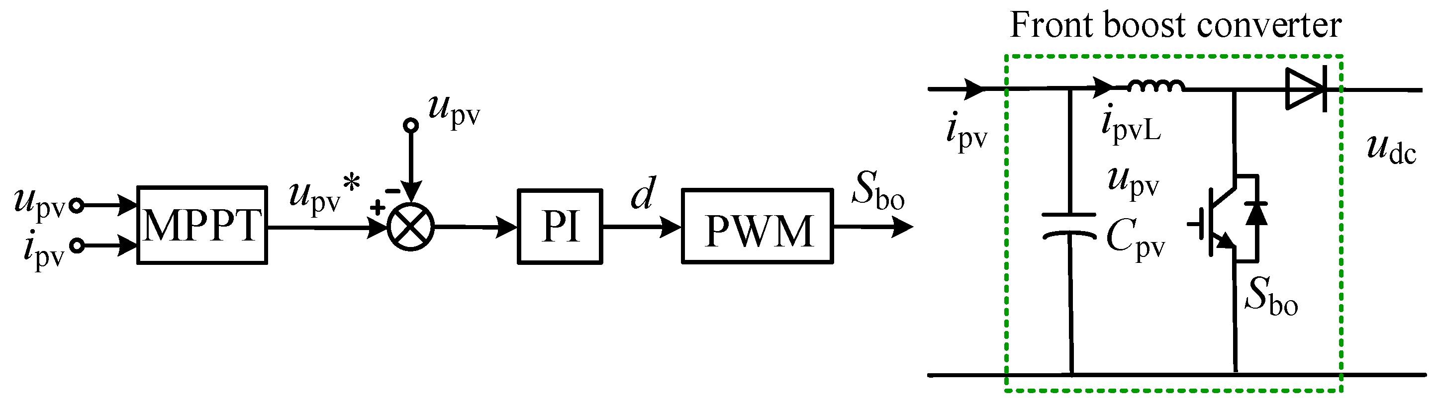
3.1. Control of the Front Boost Converter

The dynamics of the capacitor and the inductance of the PV front boost converter can be expressed as
{ C pv d u pv d t = i pv i pvL L pv d i pvL d t = u pv ( 1 d pv ) u dc
where Cpv and Lpv are the capacitor and inductance value, upv and ipv are the voltage and current of the PV array, ipvL is the inductance current, udc is the DC voltage of the grid-connected inverter, and dpv is the duty cycle of the front boost converter. Based on the dynamics of the capacitor and the inductance of the PV front boost converter, the control of the front boost converter for the maximum power point tracking (MPPT) is shown in Figure 2 and can be expressed as
d pv = ( k pb + k ib s ) ( u pv * u pv )
where u pv * is the voltage reference for the upv, which is obtained from the MPPT, and kpb and kib are the proportional and integral parameters of the controller.

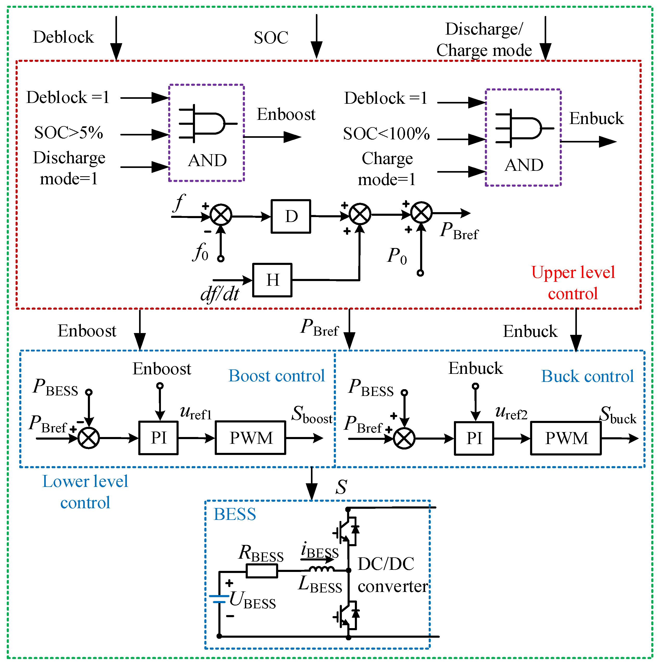
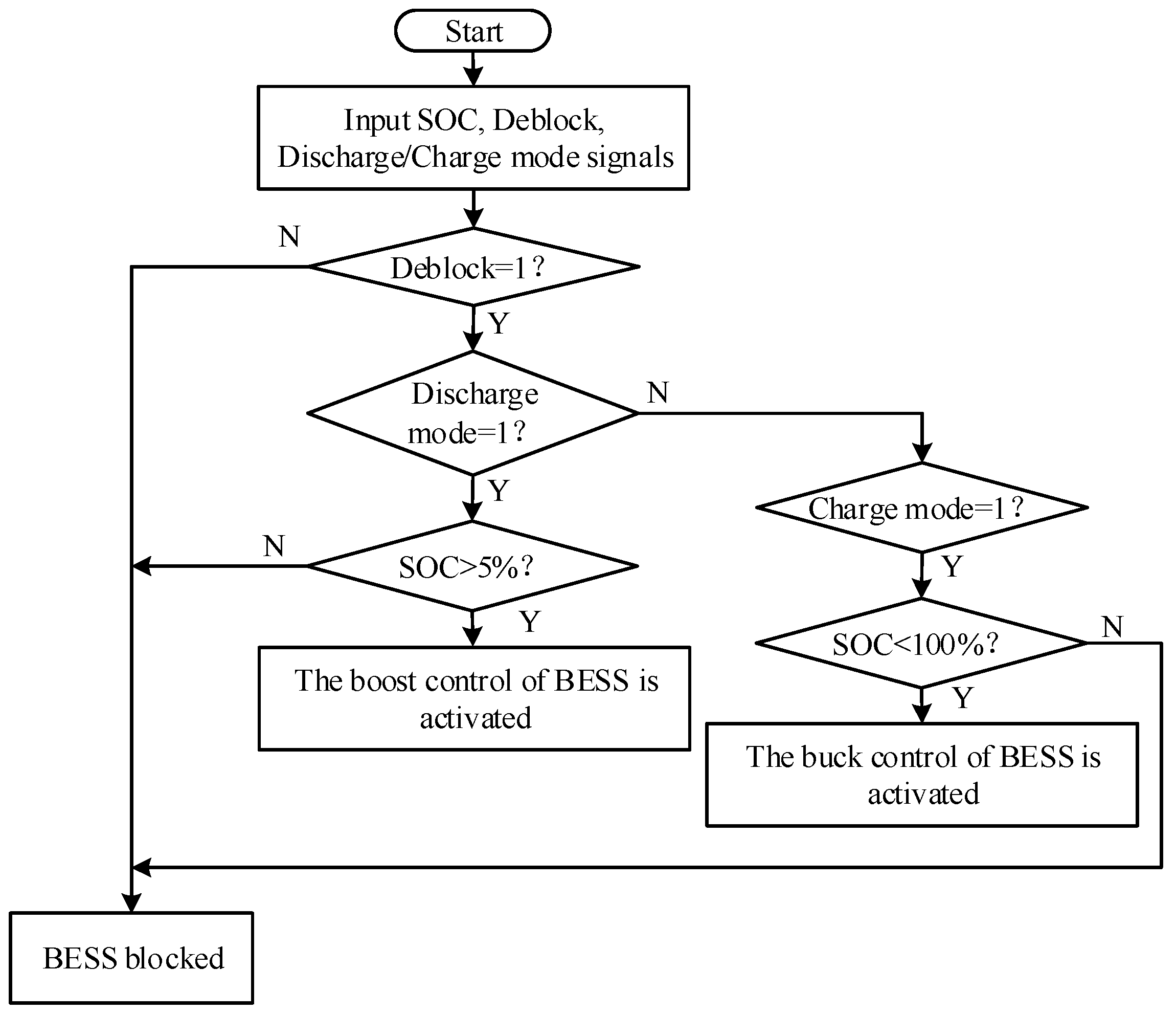
3.2. Control of the BESS

For the BESS, the control structure consists of the two layers, as shown in Figure 3. The upper-level control takes the Deblock signal, state of charge (SOC), and discharge/charge mode as the input and outputs the signal Enboost, Enbuck, and PrefBESS. Figure 4 shows the flow chart of the control logic. “Enboost” works under the following conditions: (1) The Deblock signal is equal to 1, which indicates the DC/DC converter is not blocked. (2) The SOC is larger than 5%, which indicates the battery has enough stored energy to support the AC grid. (3) The discharge signal is equal to 1, which indicates the power needs to be transmitted from the battery to the grid and the DC/DC converter should operate on the boost control mode. On the other hand, “Enbuck” works under the following conditions: (1) The Deblock signal is equal to 1, which indicates the DC/DC converter is not blocked. (2) The SOC is less than 100%, which indicates the battery has the capacity to absorb the energy. (3) The charge signal is equal to 1, which indicates the power needs to be transmitted from the grid or solar generation to the battery and the DC/DC converter should operate on the buck control mode.
The dynamic of the resistor and the inductance can be expressed as
L BESS d i BESS d t = u BESS u t + R BESS i BESS
where LBESS and RBESS are the inductance and resistance of the BESS, uBESS is the voltage of the battery, and iBESS is the output current of the battery. The control for the bidirectional DC/DC converter in the BESS is expressed as
{ u ref 1 = ( P Bref P BESS ) ( k pdc 1 + k idc 1 s )   Boost / discharging   mode   u ref 2 = ( P Bref + P BESS ) ( k pdc 2 + k idc 2 s )   Buck / charging   mode  
where PBESS is the active power of the BESS, PBref is the active power reference of the BESS, kpdc1 and kidc1 are the proportional and integral parameters for the power control in the boost/discharging mode, kpdc2 and kidc2 are the proportional and integral parameters for the power control in the buck/charging mode, and uref1 and uref2 are the voltage references for the pulse modulation width (PMW) in the two different modes, respectively.
When the grid frequency changes, in order to support the system inertia and primary frequency, the BESS active power reference PBref is determined by the upper-level control as
P Bref = H d f d t + D ( f f 0 ) + P 0
where H is the inertial time constant, D is the parameter coefficient for the primary frequency support, f is the grid frequency, f0 is the nominal frequency, and P0 is the active power feedforward term.

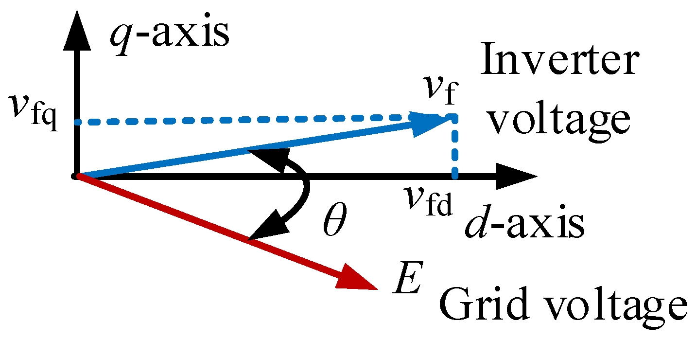
3.3. Grid-Forming Control of the Inverter

The inverter control mainly consists of the inner current control, inner voltage control, PLL-based frequency control and the DC voltage control, as shown in Figure 5.
For the grid-connected inverter, the dynamic of the inductance in the dq frame is expressed as
{ L f d i wd d t = u cd u fd + ω L f i wq R f i wd L f d i wq d t = u cq u fq ω L f i wd R f i wq
where Lf and Rf are the inductance and resistance of the grid-connected converter, ucd and ucq are the dq-axis voltage at the inverter terminal, ufd and ufq are the dq-axis voltage at the inverter filter, iwd and iwq are the dq-axis converter current, and ω is grid angular frequency.
Thus, the inner current control is designed as
{ u cd * = ( k pi + k ii s ) ( i w d * i wd ) ω L c i wq + u fd u cq * = ( k pi + k ii s ) ( i wq * i wq ) + ω L c i wd + u fq
where ucd* and ucq* are the dq-axis inverter voltage references, iwd* and iwq* are the active and reactive current references, iwd and iwq are the dq-axis inverter current, kpi and kii are the parameters of the inner current control.
On the other hand, when the inverter behaves like an AC voltage, the active power and the reactive power Pinv and Qinv can be expressed as
{ P inv = U f E sin ( θ f θ e ) X ac Q inv = ( U f E cos ( θ f θ e ) ) U f X ac
where Uf is the RMS value of the line-to-line voltage of the inverter, E is the RMS value of the line-to-line voltage of the grid, θf and θf are the phase angles of the voltages at the inverter filter and the AC grid, respectively, and Xac is the inductance between the inverter and the grid.
Considering that the relationship between the active power and reactive power and the dq-axis inverter current is
{ P inv = 1.5 u fd i wd + 1.5 u fq i wq Q inv = 1.5 u fd i wq + 1.5 u fq i wd
and the θf is mainly determined by the ufq, as shown in Figure 6, the d-axis current can be used to adjust the ufq, while the q-axis current can be used to adjust the ufd, thus the voltage control of the inverter is designed as
{ i wd * = ( k pv 1 + k iv 1 s ) ( u fq * u fq ) i wq * = ( k pv 2 + k iv 2 s ) ( u f d * u fd )
where ufd* and ufq* are the dq-axis inverter voltage references, kpv1 and kiv1 are the parameters of the q-axis voltage control parameters, and kpv2 and kiv2 are the parameters of the d-axis voltage control parameters. Generally, the values of kpv1, kiv1, kpv2, and kiv2 are chosen to ensure that the bandwidth of the voltage control loop is smaller than that of the current control loop for the sake of better system stability. In this paper, the inner current control bandwidth is designed as 300 Hz, which is smaller than fs/10, where fs is the sampling frequency of the inverter and the voltage control bandwidth is designed as one forth of the inner current control bandwidth.
For the PLL-based frequency control, it is designed as
u fq * = k f ( f * f )
where f* is the frequency reference, kf is the proportional parameter for the frequency control. The frequency f obtained from the PLL is expressed as
{ ω pll = k pp u fq + k ip s u fq f = ω pll 2 π
where kpp and kip are the parameters of the PLL and ωpll is the frequency of the PLL. When the inverter frequency reference is larger than the measured one, the ufq* is larger than 0. With the combined action of the ufq control loop and the PLL, the frequency and the phase angle will be increased. Thus, more active power can be exported. In contrast, when the inverter frequency reference is less than the measured one, the ufq* is smaller than 0. With the combined action of the ufq control loop and the PLL, the frequency and the phase angle will be decreased. Thus, less active power will be exported.
For the inverter DC capacitor, the dynamic can be expressed as
C dc d u dc d t = i dcT i dc
where Cdc is the DC capacitor value of the inverter, idcT is the DC current from the PV and BESS, and idc is the DC current of the inverter. As seen, the DC voltage is highly related to the DC current, which is related to the active power. Considering the connection between the frequency and the active power, the DC voltage control for the inverter is expressed as
f * = ( k pdc + k idc 1 s ) ( u dc * u dc ) + f 0
where u dc * is the inverter DC voltage reference and kpdc and kidc are the parameters of the DC voltage control.
When a fault happens, the inverter switches from the grid-forming mode to the current-limiting mode automatically. The dq-axis current references of the inverter are based on the look-up table. The surplus power is absorbed by the BESS and when the DC voltage of the inverter is higher than the threshold value, the chopper inside the inverter will be triggered and the power will also be consumed partly by the resistor in the chopper. When the studied system is disconnected with the AC grid, the inverter is able to work on the islanded mode, as the control provides the frequency and AC voltage establishment capability.
Compared with the existing grid-forming control without the PLL, the proposed control strategy reserves the PLL. The main advantages of the proposed control are (1) when the offline renewable generation sources try to connect to the grid, the phase of the grid can be easily obtained for smooth connection and (2) when a fault happens, the current limiting control can be achieved smoothly through the automatically switching from the grid-forming control to the inner current control loop combined with PLL.

4. Simulation Result

In order to validate the effectiveness of the proposed control, a simulation model is established in PSCAD/EMTDC, as shown in Figure 7. The solar generation is modelled as aggregated model, which is rated at 300 MW. The battery energy storage (BES) is connected to the DC side of the solar generation through a buck/boost converter. The DC voltage of the battery is at 0.5 kV and the inverter DC voltage is at 1.25 kV. The rated capacity of the BES is 16.7 (kA∙h). The other detailed parameters are presented in Table 1.

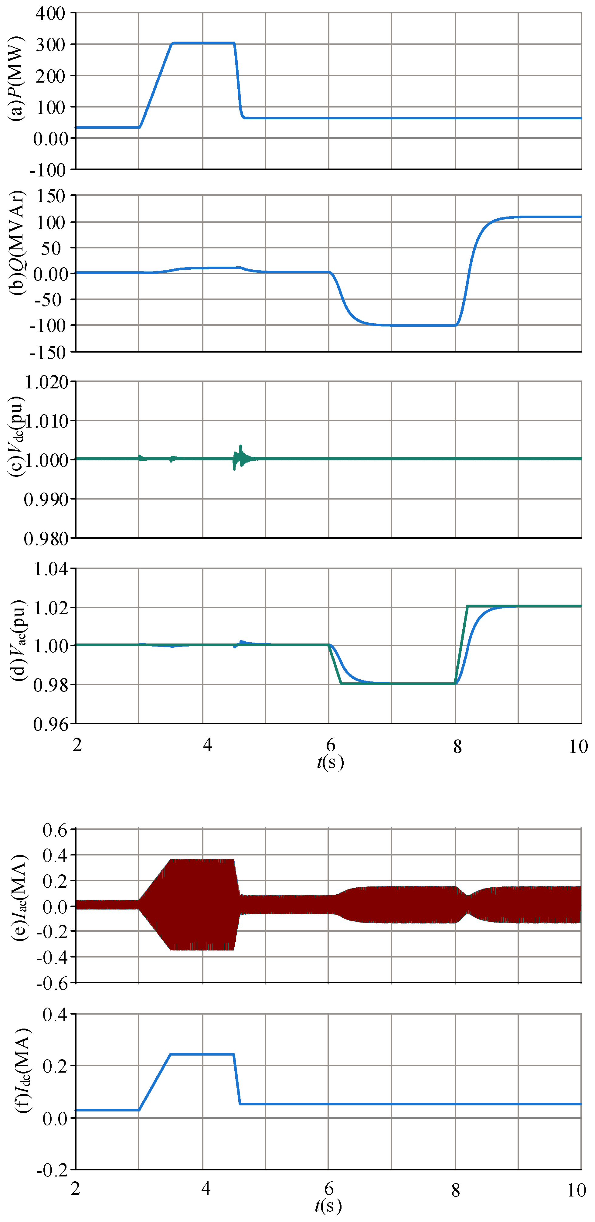
4.1. Performance Evaluation of the Grid-Forming Control during Power Variation and AC Voltage Variation

The performance of the grid-forming control is evaluated during the solar power generation variation and AC voltage variation. The timeline of the simulation is presented in Table 2.
Figure 8 shows the results of the system during such variations. As can be seen from Figure 8a, the solar power is initially generated at 30 MW before 3 s, and from 3 s to 3.5 s, the power is increased from 30 MW to 300 MW. During the active power increase, the inverter DC voltage and AC voltage can both be maintained at 1 pu, as shown in Figure 8c,d. The reactive power from the inverter sees a small increase during the power variation and is maintained at 8 MVar after 3.5 s. The magnitude of the AC current is increased from 0.035 MA to 0.35 MA, as presented in Figure 8e,f, which shows the DC current of the inverter, and the DC current is increased from 0.024 MA to 0.24 MA during 3 s to 3.5 s.
From 4.5 s to 4.6 s, the active power generation is decreased from 300 MW to 60 MW, as can be seen in Figure 8a. The DC current of the inverter is correspondingly decreased from 0.24 MA to 0.048 MA, as can be seen in Figure 8f. Figure 8c,d shows the DC voltage and AC voltage can be maintained at 1 pu after such an active power variation, although a small voltage oscillation is observed during the active power variation. Figure 8b shows the inverter reactive power. As can be seen, the reactive power is decreased from 8 MVAr to 0 MVAr from 4.5 s to 4.6 s. The magnitude of the inverter AC current decreases from 0.24 MA to 0.07 MA, as seen in Figure 8e.
From 6 s to 6.2 s, the inverter AC voltage reference decreases from 1 pu to 0.98 pu. As seen in Figure 8d, the measured AC voltage follows the reference and reaches 0.98 pu at 6.6 s. The measured AC voltage follows the reference decrease and shows the over-damped dynamic, indicating the strong stability of the voltage control. With the voltage variation, the inverter reactive power is decreased from 0 MVar to —100 MVar, as shown in Figure 8b. The inverter AC current magnitude is increased from 0.07 MA to 0.145 MA, as shown in Figure 8e. From 8 s to 8.2 s. the inverter AC voltage reference is increased from 0.98 pu to 1.02 pu, and the measured AC voltage follows the reference increase and is controlled at 1.02 pu after 8.5 s, as presented in Figure 8d. The inverter reactive power is increased from −100 MVAr to 105 MVAr, as shown in Figure 8b. The results are matched by the fact that when the AC voltage magnitude is increased, the inverter will output more reactive power. During the AC voltage variation, the AC current sees the initial decrease and then increase, as presented in Figure 8e. Such a performance is caused by the change in the absolute value of the reactive power. Figure 8a,c,f shows the performance of the inverter’s active power, DC voltage, and DC current, respectively. As can be seen, all these variables experience little change during the inverter AC voltage variation.

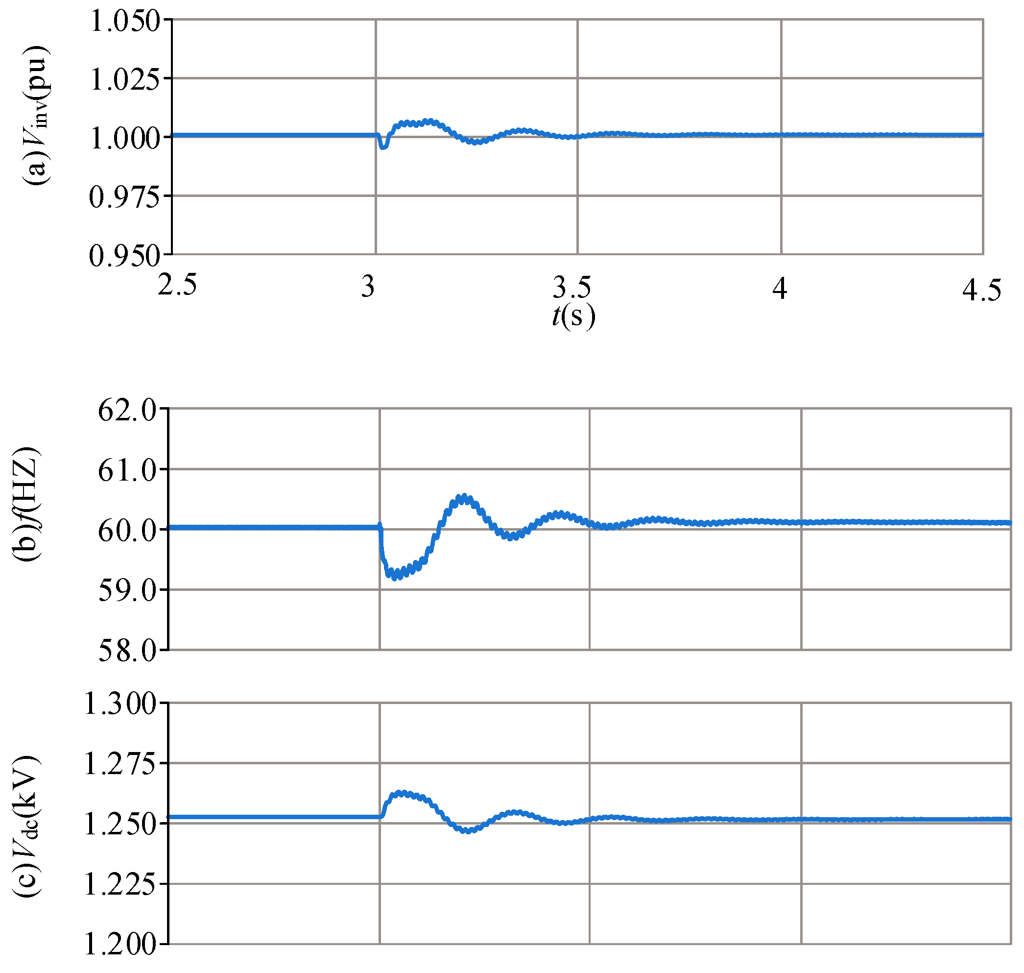
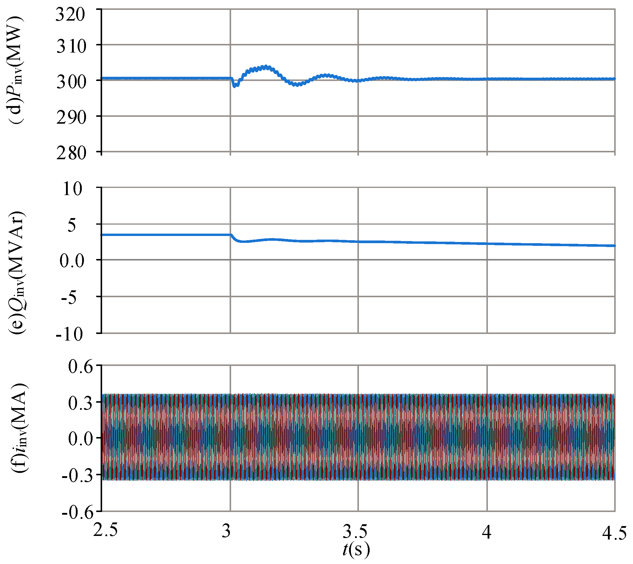
4.2. Performance Evaluation of BESS during the Grid Frequency Change

The performance of the BESS is evaluated during the grid frequency change and the corresponding results are presented in Figure 9. It is worth mentioning that the time sequence of this part is different from that of Section 4.1, so the simulation time in Figure 9 can be different from Figure 8.
From 2 s to 3 s, the grid frequency is decreased from 60 Hz to 59.6 Hz, as shown in Figure 9a. Due to the inertial and frequency support capability of the BESS, the inertia time constant of the system is 10 s and the primary frequency coefficient is 50 MW/Hz, and the active power from the BESS is increased from 0 MW to 20 MW, as presented in Figure 9b. Figure 9c,d shows the voltage of the BESS and the current of the BESS, respectively. As can be seen, the voltage is decreased from 556.8 V to 551 V and the current of the BESS is increased from 0 kA to 39 kA. Due to the discharging of the BESS, the SOC of the battery is decreased from the initial value of 94.98% at 2 s to 96.96% at 3 s, as shown in Figure 9e. With the power support from the BESS, the active power of the inverter is increased from the initial value of 150 MW to 170 MW, as shown in Figure 9f. It should be noted the initial power of 150 MW before 3 s is exported by solar generation. During the power increase from the BESS, the inverter DC voltage is increased from 1.25 kV to 1.272 kV, as shown in Figure 9g. Figure 9h shows the AC voltage of the inverter. As can be seen, the AC voltage is maintained at a constant value.
After 3 s, the grid frequency is constant at 59.6 Hz, as shown in Figure 9a. At this stage, the BESS keeps providing the active power for the primary frequency regulation and the exported active power is at 20 MW, as presented in Figure 9b–d, which demonstrates the voltage of the BESS and the current of the BESS, respectively. As can be seen, the voltage and the current are maintained at a constant value of 551 V and 39 kA. The SOC of the battery keeps decreasing and is at 94.84% at 5 s, as shown in Figure 9e–h, which shows that the inverter active power, DC voltage, and AC voltage can all operate stably after 3 s, at 170 MW, 1.25 kV, and 1 pu, respectively.

4.3. Performance Evaluation of System during the Grid Fault

The performance of the system during the grid fault is assessed and the results are presented in Figure 10. Before 3 s, the system operates at rated values with the active power at 300 MW, while the reactive power from the inverter is around 0 MVAr, as shown in Figure 10d,e. At 3 s, a three-phase fault happens and the voltage of the converter is decreased to 0.13 pu, as shown in Figure 10a,b, which shows the grid side instantaneous voltage, the magnitude of the voltage decreases from 27 kV to 3.4 kV, and the voltage is dominated by the fundamental frequency component. After the severe AC fault, the converter operates on the current-limiting control mode, and the converter AC current magnitude is controlled at 0.59 MA, as shown in Figure 10c. After 200 ms, the fault is cleared. As can be seen in Figure 10a,b, the voltage recovers to 1 pu. The inverter is no longer working on the current-limiting mode and recovers to transmit the active power. As seen in Figure 10d, the active power generation is quickly restored after the fault clearance. Figure 10e shows the reactive power recovery performance, which can also be restored to 0 MVAr, although its recovery speed is slower than the active power generation.

4.4. Performance of System during the Transition from the Grid-Connected Mode to Islanded Mode

The performance of the system during the transition from the grid-connected mode to the islanded mode is evaluated and the results are presented in Figure 11. Before 3 s, the system works on the rated value, with the AC voltage at 1 pu, frequency at 60 Hz, DC voltage at 1.25 kV, active power at 300 MW, and reactive power at 3 MVar, as shown in Figure 11a–e. At 3 s, the inverter is disconnected from the grid. As can be seen in Figure 11a,b, the voltage and frequency experience some oscillation after the operation mode switch but can stabilize after 0.8 s. Figure 11e shows the reactive power output from the inverter. As seen, before and after the mode switch, the reactive power is decreased from 3.3 MVAr to 2 MVAr. Figure 11f shows the inverter current. As can be seen, the current is not disturbed by the mode switch.

4.5. Performance of System during Phase Jump and Grid Impedance Variation

The performance of the system during phase jump is evaluated and the results are presented in Figure 12. At 3 s, the phase of the grid experiences a sudden jump, with a relatively large variation value at 30°, as seen in Figure 12a. The active power and reactive power of the inverter drift away from the initial steady-state value after such a disturbance but can stabilize after 0.1 s, as shown in Figure 12b–e, which shows the DC voltage and AC voltage, respectively. As presented, the DC voltage decreases after the AC grid phase jump while the inverter AC voltage sees a small oscillation, but both can become stable again after the disturbance. Figure 12f shows the inverter AC instantaneous current. Due to the disturbance, the three-phase current sees some harmonic components in the first place but is able to become symmetrical quickly after 40 ms.
The performance of the system during grid impedance variation is presented in Figure 13. At 3 s, the grid impedance is increased from 0.2 pu (SCR = 5) to 0.33 pu (SCR = 3), and at 4 s, the grid impedance is further increased to 0.5 pu (SCR = 2). As can be seen in Figure 13a,b, the proposed control has the capability to control the inverter active power and inverter AC voltage during different grid impedances.

5. Conclusions

This paper proposes a grid-forming control for solar generation systems with battery energy storage. The inverter control consists of the inner current control, voltage control, the PLL-based frequency control, and the DC voltage control. With the proposed control, the battery energy storage is able to provide inertial and primary frequency support during the grid frequency disturbance. Simulation models are established in PSCAD/EMTDC, and the results during the active power variation and AC variation, the grid frequency disturbance, grid fault, and mode switch validate the effectiveness of the proposed control.

Author Contributions

Methodology, Y.C. and M.W.; conceptualization and supervision, L.Y.; writing—original draft, S.L., Z.F. and W.T.; writing—review and editing W.L.; validation S.S. All authors have read and agreed to the published version of the manuscript.

Funding

This research is supported by the Science and Technology Project of State Grid Liaoning Electric Power Co., Ltd. (2023YF-90). The funder had the following involvement with the study: the study design and the decision to submit it for publication.

Data Availability Statement

The original contribution presented in this study is included in the article and further inquiries can be directed to the corresponding author.

Conflicts of Interest

Authors Yupeng Cai, Meng Wu, Shengyang Lv, Wei Li, and Songjie Shi were employed by the State Grid Liaoning Electric Power Co., Ltd. The remaining authors declare that the research was conducted in the absence of any commercial or financial relationships that could be construed as potential conflicts of interest.

References

  1. Rocabert, J.; Luna, A.; Blaabjerg, F.; Rodríguez, P. Control of Power Converters in AC Microgrids. IEEE Trans. Power Electron. 2012, 27, 4734–4749. [Google Scholar] [CrossRef]
  2. Pogaku, N.; Prodanovic, M.; Green, T.C. Modeling, Analysis and Testing of Autonomous Operation of an Inverter-Based Microgrid. IEEE Trans. Power Electron. 2007, 22, 613–625. [Google Scholar] [CrossRef]
  3. Harnefors, L.; Wang, X.; Yepes, A.G.; Blaabjerg, F. Passivity-Based Stability Assessment of Grid-Connected VSCs—An Overview. IEEE J. Emerg. Sel. Top. Power Electron. 2016, 4, 116–125. [Google Scholar] [CrossRef]
  4. Zhou, J.Z.; Ding, H.; Fan, S.; Zhang, Y.; Gole, A.M. Impact of Short-Circuit Ratio and Phase-Locked-Loop Parameters on the Small-Signal Behavior of a VSC-HVDC Converter. IEEE Trans. Power Deliv. 2014, 29, 2287–2296. [Google Scholar] [CrossRef]
  5. Fan, L. Modeling Type-4 Wind in Weak Grids. IEEE Trans. Sustain. Energy 2019, 10, 853–864. [Google Scholar] [CrossRef]
  6. Hu, J.; Huang, Y.; Wang, D.; Yuan, H.; Yuan, X. Modeling of Grid-Connected DFIG-Based Wind Turbines for DC-Link Voltage Stability Analysis. IEEE Trans. Sustain. Energy 2015, 6, 1325–1336. [Google Scholar] [CrossRef]
  7. Lin, X.; Liu, Y.; Yu, J.; Yu, R.; Zhang, J.; Wen, H. Stability analysis of Three-phase Grid-Connected inverter under the weak grids with asymmetrical grid impedance by LTP theory in time domain. Int. J. Electr. Power Energy Syst. 2022, 142, 108244. [Google Scholar] [CrossRef]
  8. Wen, B.; Boroyevich, D.; Burgos, R.; Mattavelli, P.; Shen, Z. Analysis of D-Q Small-Signal Impedance of Grid-Tied Inverters. IEEE Trans. Power Electron. 2016, 31, 675–687. [Google Scholar] [CrossRef]
  9. Sun, J. Impedance-Based Stability Criterion for Grid-Connected Inverters. IEEE Trans. Power Electron. 2011, 26, 3075–3078. [Google Scholar] [CrossRef]
  10. Zhang, X.; Xia, D.; Fu, Z.; Wang, G.; Xu, D. An Improved Feedforward Control Method Considering PLL Dynamics to Improve Weak Grid Stability of Grid-Connected Inverters. IEEE Trans. Ind. Appl. 2018, 54, 5143–5151. [Google Scholar] [CrossRef]
  11. Givaki, K.; Chen, D.; Xu, L. Current Error Based Compensations for VSC Current Control in Weak Grids for Wind Farm Applications. IEEE Trans. Sustain. Energy 2019, 10, 26–35. [Google Scholar] [CrossRef]
  12. Egea-Alvarez, A.; Fekriasl, S.; Hassan, F.; Gomis-Bellmunt, O. Advanced Vector Control for Voltage Source Converters Connected to Weak Grids. IEEE Trans. Power Syst. 2015, 30, 3072–3081. [Google Scholar] [CrossRef]
  13. Zhang, L.; Harnefors, L.; Nee, H. Power-Synchronization Control of Grid-Connected Voltage-Source Converters. IEEE Trans. Power Syst. 2010, 25, 809–820. [Google Scholar] [CrossRef]
  14. Zhang, L.; Harnefors, L.; Nee, H. Interconnection of Two Very Weak AC Systems by VSC-HVDC Links Using Power-Synchronization Control. IEEE Trans. Power Syst. 2011, 26, 344–355. [Google Scholar] [CrossRef]
  15. Liu, J.; Miura, Y.; Ise, T. Comparison of Dynamic Characteristics Between Virtual Synchronous Generator and Droop Control in Inverter-Based Distributed Generators. IEEE Trans. Power Electron. 2016, 31, 3600–3611. [Google Scholar] [CrossRef]
  16. Meng, X.; Liu, J.; Liu, Z. A Generalized Droop Control for Grid-Supporting Inverter Based on Comparison Between Traditional Droop Control and Virtual Synchronous Generator Control. IEEE Trans. Power Electron. 2019, 34, 5416–5438. [Google Scholar] [CrossRef]
  17. Wu, W.; Chen, Y.; Zhou, L.; Luo, A.; Zhou, X.; He, Z.; Yang, L.; Xie, Z.; Liu, J.; Zhang, M. Sequence Impedance Modeling and Stability Comparative Analysis of Voltage-Controlled VSGs and Current-Controlled VSGs. IEEE Trans. Ind. Electron. 2019, 66, 6460–6472. [Google Scholar] [CrossRef]
  18. Li, M.; Wang, Y.; Hu, W.; Shu, S.; Yu, P.; Zhang, Z.; Blaabjerg, F. Unified Modeling and Analysis of Dynamic Power Coupling for Grid-Forming Converters. IEEE Trans. Power Electron. 2022, 37, 2321–2337. [Google Scholar] [CrossRef]
  19. Mallemaci, V.; Mandrile, F.; Rubino, S.; Mazza, A.; Carpaneto, E.; Bojoi, R. A comprehensive comparison of Virtual Synchronous Generators with focus on virtual inertia and frequency regulation. Electr. Power Syst. Res. 2021, 201, 107516. [Google Scholar] [CrossRef]
  20. Barać, B.; Krpan, M.; Capuder, T.; Kuzle, I. Modeling and Initialization of a Virtual Synchronous Machine for Power System Fundamental Frequency Simulations. IEEE Access 2021, 9, 160116–160134. [Google Scholar] [CrossRef]
Figure 1. Topology of the studied system.
Energies 17 03642 g001
Figure 2. Control of the front boost converter.
Energies 17 03642 g002
Figure 3. Control of the BESS.
Energies 17 03642 g003
Figure 4. Flow chart of the control logic.
Energies 17 03642 g004
Figure 5. Proposed grid-forming control of the inverter.
Energies 17 03642 g005
Figure 6. Voltage vector of the inverter and grid.
Energies 17 03642 g006
Figure 7. Simulation model in PSCAD/EMTDC of the studied system.
Energies 17 03642 g007
Figure 8. Simulation results during power variation and AC voltage variation: (a) inverter active power; (b) inverter reactive power; (c) inverter DC voltage; (d) inverter AC voltage (RMS); (e) inverter instantaneous AC current; (f) inverter DC current.
Energies 17 03642 g008
Figure 9. Simulation results of BESS during the grid frequency change: (a) grid frequency; (b) battery power; (c) battery voltage; (d) battery current; (e) state of charge; (f) inverter active power; (g) inverter DC voltage; (h) inverter AC voltage.
Energies 17 03642 g009
Figure 10. Simulation results of the system during the grid fault: (a) grid PCC voltage (RMS); (b) grid PCC instantaneous voltage; (c) inverter current; (d) inverter active power; (e) inverter reactive power.
Energies 17 03642 g010
Figure 11. Simulation results during the transition from the grid-connected mode to islanded mode: (a) inverter AC voltage; (b) inverter frequency; (c) inverter DC voltage; (d) inverter active power; (e) inverter reactive power; (f) inverter AC instantaneous current.
Energies 17 03642 g011aEnergies 17 03642 g011b
Figure 12. Simulation results during phase jump: (a) grid instantaneous AC voltage; (b) inverter active power; (c) inverter reactive power; (d) inverter DC voltage; (e) inverter AC voltage; (f) inverter AC instantaneous current.
Energies 17 03642 g012
Figure 13. Simulation results during grid impedance ratio variation: (a) inverter active power; (b) inverter AC voltage.
Energies 17 03642 g013
Table 1. Parameters of the system.
ParametersValues
BESSDC voltage0.5 kV
Rated Capacity16.7 (kA∙h)
Resistive Drop0.001 pu
Voltage at Exponential Point1.03 pu
Inductance and capacitor in DC/DC0.2 μH
3000 mF
0.5 μH
InverterRating300 MVA
DC voltage1.25 kV
AC voltage0.69 kV
DC capacitor30,000 mF
Transformer ratio0.69/33 kV
Transformer inductance and resistor0.08, 0.002 pu
Converter reactance and resistor0.15 pu, 0.0015 pu
Filter capacitor and resistor0.10 pu, 0.001 pu
Table 2. Sequence of simulation.
TimeEvents
0–3 sSolar power generation at 0.1 pu, BES operation off
3–3.5 sSolar power generation increases from 0.1 pu to 1 pu
4.5–4.6 sSolar power generation decreases from 1 pu to 0.2 pu
6–6.2 sInverter AC voltage decreases from 1 pu to 0.98 pu
8–8.2 sInverter AC voltage increases from 0.98 pu to 1.02 pu
Disclaimer/Publisher’s Note: The statements, opinions and data contained in all publications are solely those of the individual author(s) and contributor(s) and not of MDPI and/or the editor(s). MDPI and/or the editor(s) disclaim responsibility for any injury to people or property resulting from any ideas, methods, instructions or products referred to in the content.

