Article

Hybrid ANPC Grid-Tied Inverter Design with Passivity-Based Sliding Mode Control Strategy

School of Electronic and Electrical Engineering, University of Leeds, Leeds LS2 9JT, UK
*
Author to whom correspondence should be addressed.
Energies 2024, 17(15), 3655; https://doi.org/10.3390/en17153655
Submission received: 15 June 2024 / Revised: 19 July 2024 / Accepted: 22 July 2024 / Published: 25 July 2024
(This article belongs to the Special Issue Energy, Electrical and Power Engineering 2024)

Abstract

:
Voltage source inverters are extensively used in the grid connection of renewable energy-sourced generators, and multilevel converters, in particular, have attracted a great deal of attention in recent years. This paper investigates the application of a novel passivity-based sliding mode (PSM) control scheme on three-level grid-tie active Neutral-Point-Clamped (ANPC) inverters that yield fast and stable responses to grid impedance variations. Simulation studies confirm that this control scheme can produce high tracking performance and is also robust against grid load variations. Furthermore, to enhance ANPC efficiency, the loss distribution of switching devices controlled by the proposed strategy is evaluated. An optimal scheme is finally proposed for allocating silicon and Wide-Band-Gap switching devices, resulting in a hybrid ANPC inverter capable of achieving a desirable trade-off between the power losses and the device cost.

1. Introduction

Recent decades have witnessed high penetrations of renewable energy-sourced generators in the power grid. Voltage-sourced inverters (VSI) have been extensively used for interfacing renewable energy sourced generations (RESGs) to the utility grid at various voltage levels. Most VSIs used are the two-level H-bridge type with an output filter due to their simple structure and high efficiency [1,2,3,4]. A current trend has seen RESGs connected directly to the medium voltage distribution network for improved efficiency, along with a growing use of multilevel inverters. With their ability to output multiple voltage levels, multilevel inverters offer switching at reduced frequencies, have lower voltage stress on each switch, and generate waveforms with reduced harmonics [5,6,7]. These advantages make them a promising option to ensure the stable and robust operation of power networks.
Among a range of multilevel inverters, the 3-level Neutral-Point-Clamped (NPC) [8,9,10,11,12] inverter is one of the most preferred as it has a simple structure, a lower switching device count, and requires no floating capacitors. However, this structure’s one major disadvantage is the unequal loss distribution among the semiconductor switches, which limits the converter operating range and performance. Variants of NPC, such as 3-level Active Neutral-Point-Clamped (ANPC) [13,14] and T-type Neutral-Point-Clamped (T-NPC) [15,16,17,18,19] inverters, have since been developed. These offer improved device loss balance while having similar advantages to a 3-level NPC. This paper focuses on a 3-level ANPC for grid converter application. A 3-level ANPC consists of six bidirectional switches; two of them are anti-parallel, connected with the clamp diodes in the path to the neutral point, and offer three zero output voltage switching states. Assisted with careful zero-state selection and switching strategy optimization, the ANPC converter can produce a better waveform than that of the NPC converter [20]. By further utilizing the Phase-Shift PWM (PS-PWM), the ANPC inverter can also balance the stress on all switches, leading to reduced maintenance costs and extended lifespan. This merit also makes it possible for ANPC inverters to be used in power distribution networks as well as drive systems [21,22,23,24,25].
A challenging issue for the grid-tie VSIs, regardless of their circuit topologies, is the maintenance of operational performance. With the proliferation of dispersed RESGs, the strength of the power grid may be weakened [26,27,28]. For example, as many renewable generators are located in areas remote to the load centers, the transmission lines required for connection need to span long distances and cross varied terrain, adding significant line impedance to the power grid; as a result, power grid stability and the transmission efficiency of the grid are affected [29,30,31]. To guarantee the stable and highly efficient operations of a weak grid, many control strategies have been proposed in the literature. In [32], an impedance shaping strategy for grid-connected H-bridge inverters with LCL filters is proposed. The method imposes virtual parallel and serial impedances into the grid current control loop to compensate for the variations of grid impedance, hence improving the VSI’s adaptability to varying grid conditions. However, this method is sensitive to system delays, and impedance parameter design can be complicated. In [33], a nonlinear power damping control of a grid-connected VSC was developed. The proposed controller provides active damping and synchronization power, and it is capable of attenuating power, frequency and load angle oscillations, and synchronizing the VSC with the grids under varied conditions. However, implementing this complex hybrid control strategy presents some practical challenges, and it has not yet been experimentally validated. Therefore, it is not possible to judge the feasibility and effectiveness of the proposed solution in real-world settings, although some data-driven intelligent methods have been proposed to improve the control performance [34,35]. Amongst them, the passivity-based sliding mode (PSM) control scheme is an important method which has drawn much attention. Passive control is a nonlinear control strategy. Based on the Euler–Lagrange (EL) model of the system to be controlled, it is established with a natural damping injection and offers the advantages of a fast response, strong robustness, a simple system structure, and easy implementation. Combining passive control with sliding mode control (SMC), it is possible to deal with grid parameter changes and external interference. This control scheme has been applied to the inner current control loop of an MMC-UPFC [36], which performs power flow control for a 220 kV transmission line. The MMC has 27 voltage levels per phase and a 50 MW power rating. The results show that under PSM control, the system remains stable with outer disturbance and variable system parameters. In [37], the PSM controller was also applied to a 27-level modular multilevel converter (MMC) for a 220 kV line power flow control to improve the system’s dynamic responses.
Given the aforementioned progress, investigations into using PSM for the control of grid-connected converters, particularly at medium voltage levels (1000 V to 50 kV) and with a weak grid, are few but necessary. This paper proposes a PSM controller for grid-connected ANPC inverters in medium-voltage applications. An Euler–Lagrange model of a 3-phase ANPC inverter, taking into account both the output LC filter and grid impedance, is built, and the system is shown to be strictly passive with a natural damping injection. Not only does this enable the ANPC inverter to quickly track the desired current reference values, but it also enhances the system’s robustness in the presence of load variations in the grid.
This paper further explores the development of a highly efficient grid-tied ANPC using a hybrid structure comprising Wide-Band-Gap (WBG) and silicon (Si) switching devices. It is well understood that WBG devices made of silicon carbide (SiC), gallium arsenide (GaAs), and gallium nitride (GaN) have smaller reverse recovery currents and times; therefore, they can operate at higher switching frequencies with very low switching loss. The use of these devices can reduce the sizes of passive components in the circuit, hence reducing the volume and cost of the converters and improving overall system efficiency [38]. However, these devices have their respective shortcomings, and their prices are significantly higher than those of Si-IGBTs. The hybrid structure is thought to be a viable solution to strike a balance between efficiency and cost and has been investigated by various researchers. Reference [39] presents an ANPC with the Si/SiC hybrid structure and shows its improvements in efficiency. In [40], a modulation strategy was developed while considering the switching loss on SiC devices, and the conduction loss of the devices was reduced by parallel operation so as to give the best hybrid structure. GaN materials have great development potential given their fast-switching operations, but their performances have not been compared extensively with SiC and Si devices. In this paper, the loss distribution of each bridge arm is examined under the PSM scheme. Based on the analysis, an optimal hybrid structure of Si/WBG structure is then proposed, taking into account the performance of SiC and GaN devices and balancing both the cost and losses.
The rest of the paper is structured as follows: In Section 2, the hybrid ANPC topology and switching states are reviewed, and the configuration of a grid-tied ANPC inverter is presented. Section 3 describes the Euler–Lagrange model of the system in a d-q frame, and the passive-based system theory is explained in detail. The principles of the SMC scheme for flexible damping change are discussed, and the new PSM controller for the ANPC inverter is presented. Simulation studies of the PSM considering the load and transmission line impedance variations are conducted, and the reference tracking performances are presented. The loss analysis and simulation results for the hybrid ANPC inverter with a mixed-use of Si/WBG devices are also given in Section 3. Section 4 concludes the paper.

2. Design of PSM Controller for Hybrid ANPC Grid-Tied Inverters

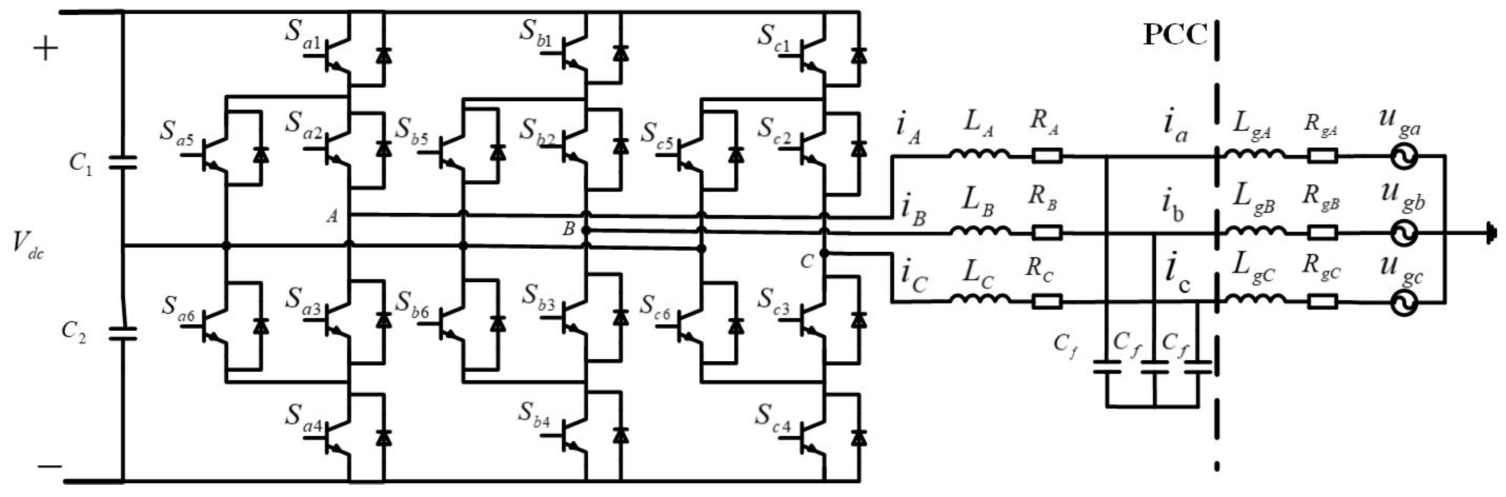
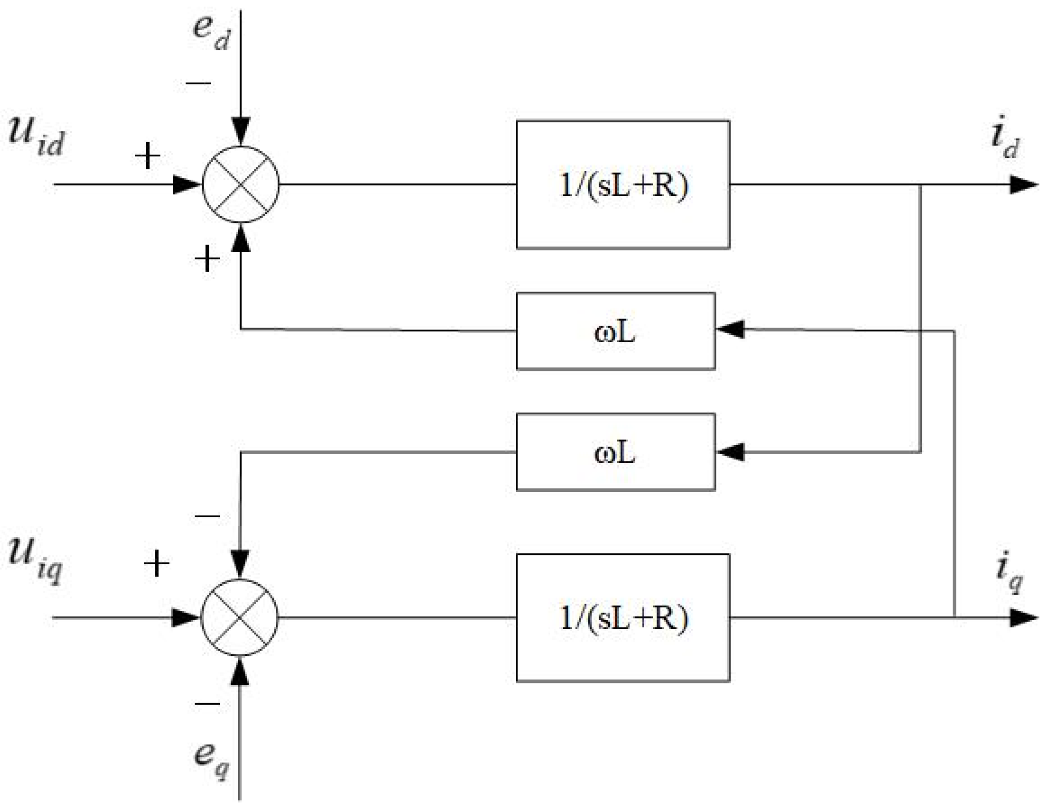
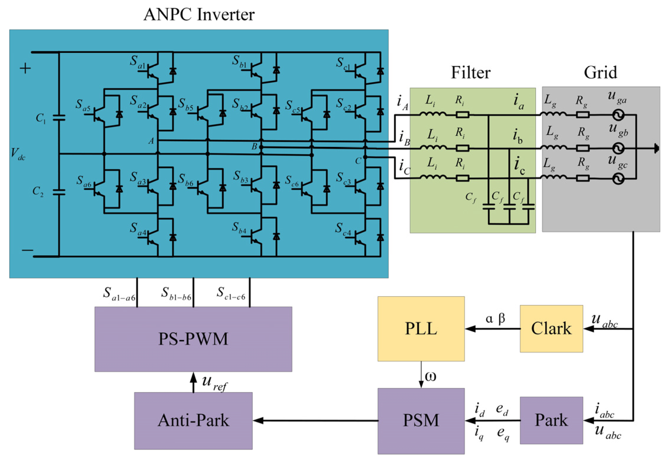
2.1. Hybrid ANPC Grid-Tied Inverter Model

This study investigates the Si/WBG hybrid grid-tied ANPC inverter. Using the same topology but with different switching devices would produce the same output waveforms; the only difference is the loss incurred in the inverter, which will be discussed in detail in Section 3. The structure of a grid-tied ANPC inverter with its LC filter is illustrated in Figure 1. In contrast to a standard NPC inverter, it has two bidirectional switches instead of two diodes to clamp to the neutral point. This is beneficial to balance the utilization of the upper and lower neutral paths during the zero-voltage states of the inverter, thus improving the loss-distribution of the inverter and device utilization.
As illustrated in Figure 2, PS-PWM is used to control where two carrier waves with a 180° phase difference but the same frequency are applied and compared to the reference sine wave to generate the switching control pulses.
Figure 3 illustrates the principle of the ANPC. Take one leg as an example. There are six switches which can be grouped according to the complementary sets. For PS-PWM, the three sets of complementary switching groups are, respectively, Sa1/Sa5, Sa2/Sa3, Sa4/Sa6.
The double-frequency output voltage waveforms are the consequence of two zero-voltage states (ZVS) for the positive and negative voltage cycles, respectively, as shown in Figure 3b,d. While Figure 3a,c show the positive and negative states, there are two zero-voltage states (ZVS) for the positive and negative voltage cycles, respectively. The advantage of this method is that it allows for an even distribution of losses among the six switches, preventing one switch from experiencing undue voltage stress. This helps to prolong the device’s service life. Figure 4 illustrates the PWM waveform for each switch in positive and negative cycles, and the switching states are summarized in Table 1.
According to Kirchhoff’s voltage law, the terminal voltages uio (i = A, B, C) of the ANPC can be expressed as
u A O = L A d i A d t + R A i A + L g A d i a d t + R g A i a + u g a + u n o u B O = L B d i B d t + R B i B + L g B d i b d t + R g B i b + u g b + u n o u C O = L C d i C d t + R C i C + L g C d i c d t + R g C i c + u g c + u n o
where uga, ugb, ugc are the grid phase voltages, uno is the voltage between the grid three-phase ground and the converter DC-bus neutral point, and it is zero for all three phases since it is assumed to be a balanced three-phase grid. Ri and Li are the parameters of the filter inductances, while Rgi, Lgi represent the grid-side distribution line impedance. The inverter-side currents are expressed as ii, and the grid-side three-phase currents are denoted as ia, ib, ic, respectively. Assuming no filter capacitor is used, hence iA = ia, iB = ib, iC = ic, the model Equation (1) can be simplified as
u A O = L d i A d t + R i A + u g a u B O = L d i B d t + R i B + u g b u C O = L d i C d t + R i C + u g c
where L = Li + Lgi and R = Ri + Rgi. Considering a balanced converter circuit and the grid and applying reference transformation from a-b-c stationary frame to a d-q frame rotating synchronously with the grid voltage, the d-q form of the model equations in (2) are given as
u i d = L d i d d t + R i d ω L i q + e d u i q = L d i q d t + R i q + ω L i d + e q
where uid and uiq are the d-q elements of the ANPC three-phase terminal voltages; id and iq are the equivalent three-phase AC current on the d-q axis; ω = 2πf is the angular frequency of the grid voltage; ed and eq are the components of the three-phase grid AC voltage in d-q form.
Expressing Formula (3) in matrix form, the following is derived:
L 0 0 L d i d d t d i q d t + 0 ω L ω L 0 i d i q + R 0 0 R i d i q = u i d e d u i q e q
We then write the expression in Euler–Lagrange form as follows:
D x ˙ + E x + R x = u
where
D = L 0 0 L .   E = 0 ω L ω L 0 .   R = R 0 0 R . u = u i d e d u i q e q .   x = i d i q .   x ˙ = d i d d t d i q d t
Figure 5 is the block diagram of the entire system.

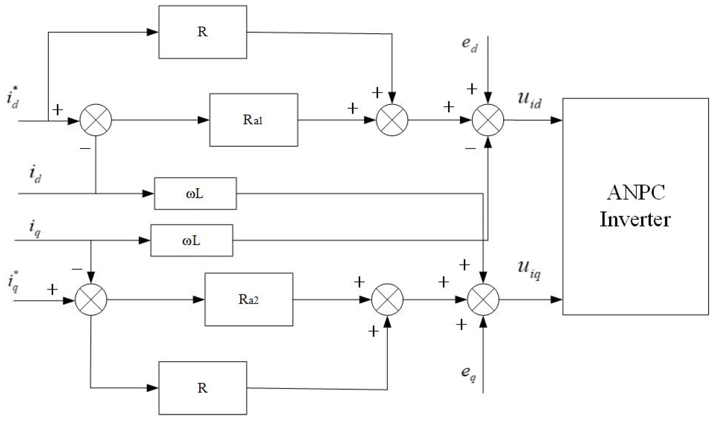
2.2. Passive System and Controller Design

A passive system merely transfers, stores, and consumes energy; it does not have any means of producing energy. To deliver the intended outcome, it reconfigures parameters in the system from an energy standpoint. For an m-input m-output system with n states
x ˙ = f x , u y = h x , x 0 = x 0 R n
where x and u are the system state and input vectors, respectively, while y is the output vector of the system and is continuous with respect to x, and f and h are Lipschitz functions.
The following dissipation inequalities are satisfied if there is a positive definite function G(x) and a continuously differentiable positive semidefinite energy storage function F(x) at any time:
F x t F x 0 0 t y T u d τ 0 t G x d τ
Or
F ˙ x y T u G x
Then, the system is strictly passive [41].
y T u is the rate of energy injected into the system by external input.
Then, the energy storage function needs to be selected as follows:
F x = x T D x 2
Its differential expression can be obtained as follows:
F ˙ x = x T D x 2 x · f x , u
Since M is a symmetric matrix with respect to x, the above formula can be written as
F ˙ x = x T D x ˙
Substitute Equation (5) into the above Equation (11), yielding
F ˙ x = x T u E x R x = x T u x T E x x T R x
where
x T E x = i d i q T 0 ω L ω L 0 i d i q = 0
then
F ˙ x = x T u x T R x
Equation (14) satisfies the form of the passive expression of the system, so it can be proved that the system is passive. The expected equilibrium point of the system can be defined as
x * = i d * i q *
where id* and iq* are the expected stable values of the system.
At the same time, the system errors are
x e = x x * u e = u u *
where u* is the expected input of the system.
Then, Equation (5) can be reformulated as
D x ˙ + E x + R x = u D x ˙ * E x * R x *
Then, Equation (11) can be reformulated as
F ˙ x e = x e T D x ˙ e = x e T u D x ˙ * E x * + x e R x * + x e
To speed up the system’s convergence to the reference point, extra damping must be injected, and energy dissipation must be accelerated so that the total damping dissipation equals Rd, where
R d x e = R + R a x e R a = R a 1 0 0 R a 2
and Ra is the positive definite matrix with injected damping; Ra1 and Ra2 are the components of the matrix.
Then
D x ˙ e + R d x e = u D x ˙ * E x R x * + R a x e
Eliminate the steady-state error and set the right-hand side of the equation to 0.
u = D x ˙ * + E x + R x * R a x e
The combination of (19), (17), and (11) yields
F ˙ x = x e T D x ˙ e = x e T R + R a x e < 0
It is shown that the convergence rate of the error energy function can be accelerated by taking u as defined in Equation (20), which can be further rewritten as
L 0 0 L d i d * d t d i q * d t + 0 ω L ω L 0 i d i q + R 0 0 R i d * i q * R a 1 0 0 R a 2 i d i d * i q i q * = u i d e d u i q e q
where
L 0 0 L d i d * d t d i q * d t = 0
The passive control diagram of the system is shown in Figure 6.

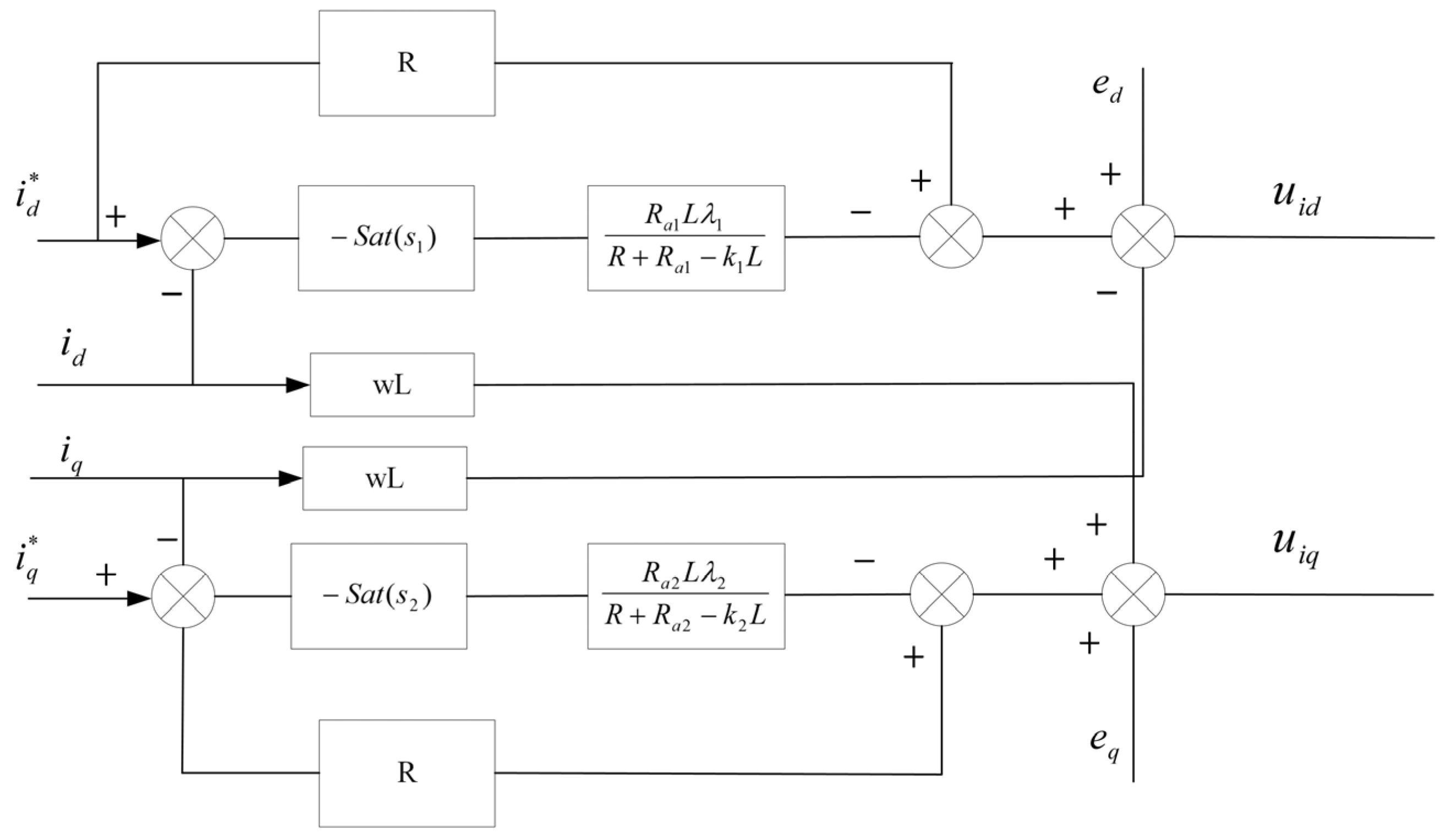
2.3. PSM Controller Design

Grid impedance frequently varies when renewable energy is connected to or disconnected from the system, a condition that conventional controllers are unable to handle. When external disturbances occur and the system’s parameters vary over time, the passive controller helps the system quickly attain the intended state by injecting damping. However, the system’s weak resilience to disturbances negatively impacts the system’s performance. On the other hand, the SMC is more robust and is not affected by variations in the system’s parameters while the SMC’s response time is also longer. The two control algorithms are combined to perform the PSM control of the inner loop. Firstly, according to SMC theory, the sliding mode surface is selected.
s 1 = i d i d * s 2 = i q i q *
The saturation function is selected to define the surface
s ˙ 1 = λ 1 s a t s 1 k 1 s 1 s ˙ 2 = λ 2 s a t s 2 k 2 s 2
where λ1 and λ2 and k1 and k2 are the coefficients of the approach rate, which are all greater than 0.
s a t s = 1 , s > Δ s Δ , s Δ 1 1 , s Δ < 1
where Δ is the coefficient in the saturation function.
Merging (24) and (3) yields
u i d = R i d ω L i q + e d L λ 1 s a t s 1 + k 1 s 1 u i q = R i q + ω L i d + e q L λ 2 s a t s 2 + k 2 s 2
while Equation (25) is combined with (22), yielding
i d i d * = L λ 1 s a t i d i d * R R a 1 k 1 L i q i q * = L λ 2 s a t i q i q * R R a 2 k 2 L
Then, the PSM controller is defined as follows:
0 ω L ω L 0 i d i q + R 0 0 R i d * i q * R a 1 0 0 R a 2 L λ 1 s a t ( i d i d * ) R + R a 1 k 1 L L λ 2 s a t ( i q i q * ) R + R a 2 k 2 L = u i d e d u i q e q
The control system block diagram is shown in Figure 7.

2.4. Simulation and Results

The control block diagram of the ANPC grid-connected inverter with the PSM controller is shown in Figure 8. The three-phase voltage and current obtained from the power grid are used to derive the corresponding D and Q axis components and the phase angle of the power grid by means of Park transformation and phase-locked loop (PLL). It is assumed that the three-phase voltage of the grid is balanced. The PSM controller receives the information and generates control signals for all the switches, which it then uses to run the inverter and feed the required current into the power grid. Matlab/Simulink 2023a is used to build the model, implement the control strategies, and analyze the output waveform.
Specific parameters of the system of the controllers are listed in Table 2 and Table 3, respectively:
Considering that the resistance and inductance of the network side may vary significantly during peak power consumption, the controller needs to respond quickly to the parameter variations and disturbances introduced into the power grid. Thus, in this study, to validate the performance of the PSM controller, two scenarios are considered: (1) impedance variations on the grid side; (2) changes in the output reference current.

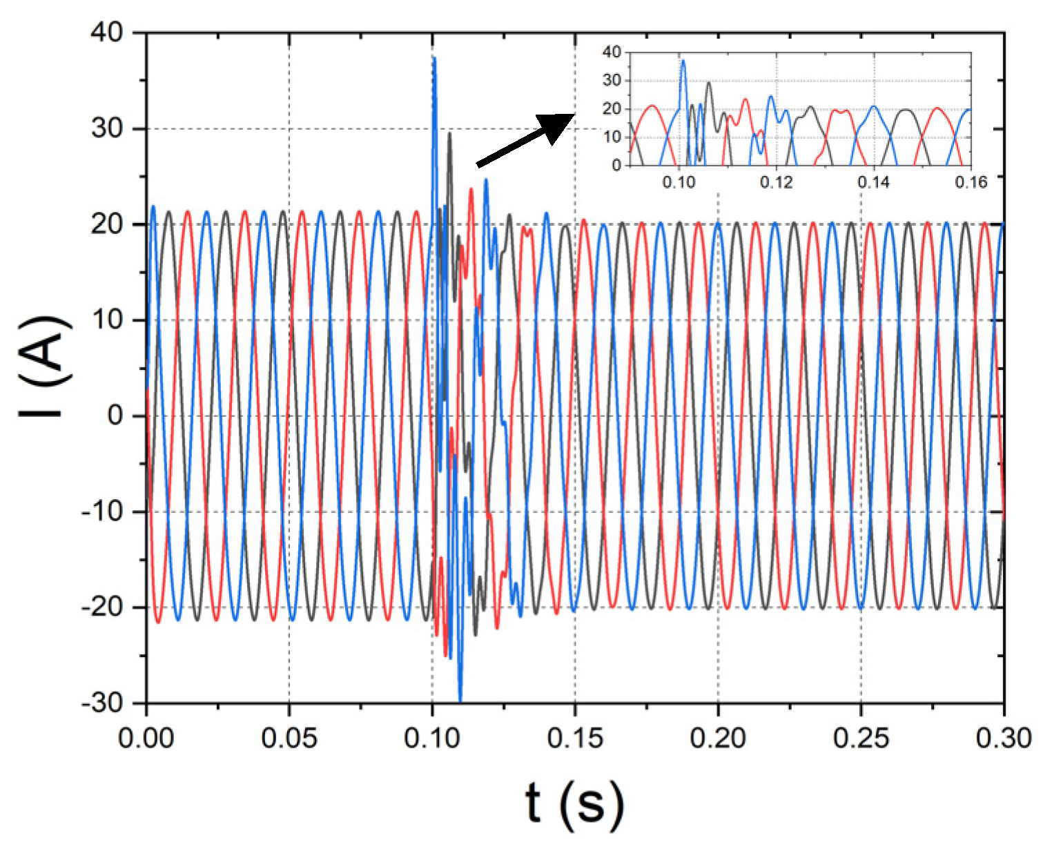
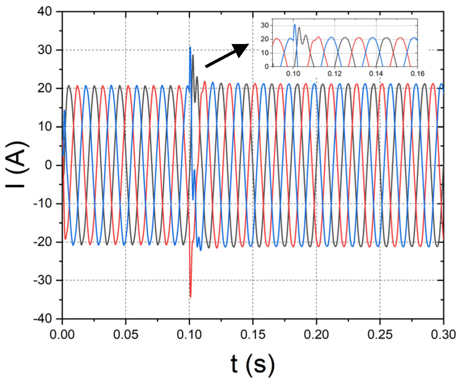
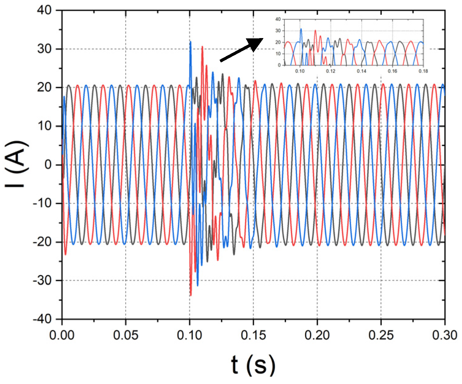
2.4.1. Impedance Variations on the Grid Side

To test the robustness of the controllers, a 5 Ω resistor and a 1 mH inductance are added to the network side at 0.1 s. When the load changes abruptly, the output waveforms of the three controllers are shown in Figure 9, Figure 10 and Figure 11, respectively.
It is evident that the passive control produces far more overshoots than the other two controllers as the network-side load changes significantly. Also, the passive control is not robust enough because the output current drops in the new stable condition even though it reaches a new equilibrium state at 0.15 s. The SMC’s dynamic performance is poor, even though its overshoot is similar to the PSM controller; the system takes 0.184 s to stabilize, but even then, the output current stays at 20 A, indicating the SMC’s strong anti-interference capabilities; the PSM’s new steady state was reached in 0.125 s, and its overshoot is essentially the same as the SMC’s.

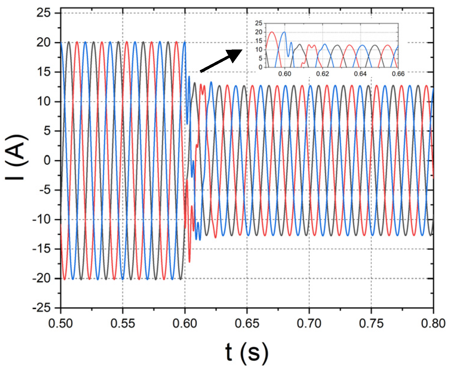
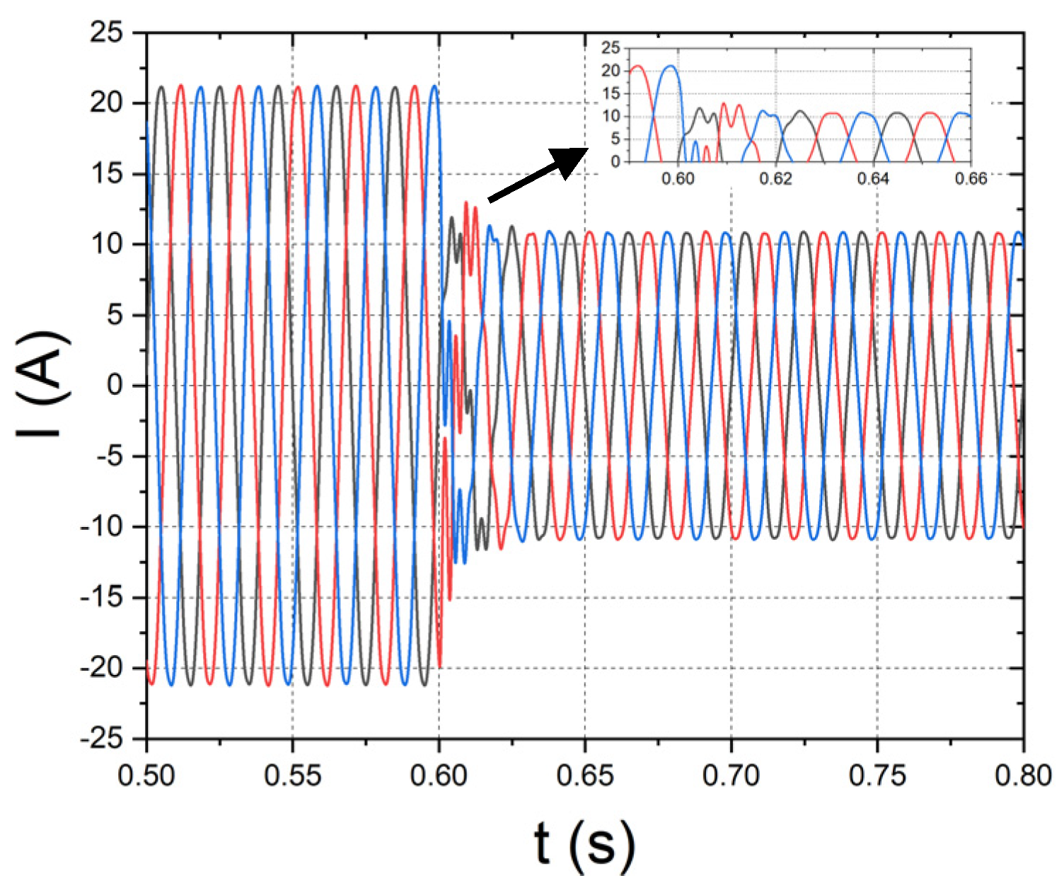
2.4.2. Changes in Output Reference Current

The output reference current is decreased from 20 A to 10 A at 0.6 s in order to compare the dynamic responses of the three controllers, namely the passive controller, the SMC, and the PSM controller. Figure 12, Figure 13 and Figure 14 show the output waveforms of the three controllers, respectively, following a change in the reference current.
The passive control responds more quickly than the other two controllers when the reference current changes (restoring stability in 0.625 s), followed by the PSM control (restoring stability in 0.645 s) and the sliding mode control (restoring stability in 0.645 s). However, the passive control exhibits a significant steady-state error, while the PSM control demonstrates a high level of accuracy. The PSM control can effectively handle the load variations on the network side, retaining the merits of the other two approaches while performing exceptionally well in both transient and steady-state performance with an acceptable THD of approximately 0.91%.

3. Design of Hybrid Inverter Based on Loss Analysis

A key factor influencing an inverter’s efficiency is the conversion loss, including switching loss and conduction loss. While it is desirable to increase the switching frequency to lower output waveform distortion and filter size, which lowers the inverter’s volume, the switching loss will inevitably rise as a result of the higher switching frequency. GaN MOSFETs feature a minimum drift area resistance that is approximately 2781 times lower than Si, and they have exceptionally high electron mobility. As a result, GaN materials can dramatically reduce on-loss and have a very low on-resistance [42], while SiC materials have a very high blocking voltage of nearly 1700 V and a comparatively modest current of 8 A [43]. Furthermore, WBG devices perform better thermally; SiC MOSFET and GaN HEMT typically have maximum temperatures between 150 and 175 °C [44]. In the past three decades, WBG materials—particularly SiC and GaN—have emerged as the most auspicious semiconductor materials, offering numerous advantages over silicon. These elements are now used in the design of conversion systems that integrate renewable energy sources. WBG devices do, however, have many drawbacks, one of which is their high cost because of their costly fabrication process.
The power loss analysis of each of the six switches in an ANPC’s single phase leg is conducted as follows: Si, SiC, and GaN devices are used as switches in the inverter. Commercial products of the three devices are used, including the Infineon IGW60T120 Si IGBT (USD 9.92) [45], the Wolfspeed C2M0040120D N-Channel SiC MOSFET (USD 45.52) [46], and the GS-065-060 GaN (USD 42.4) [47].

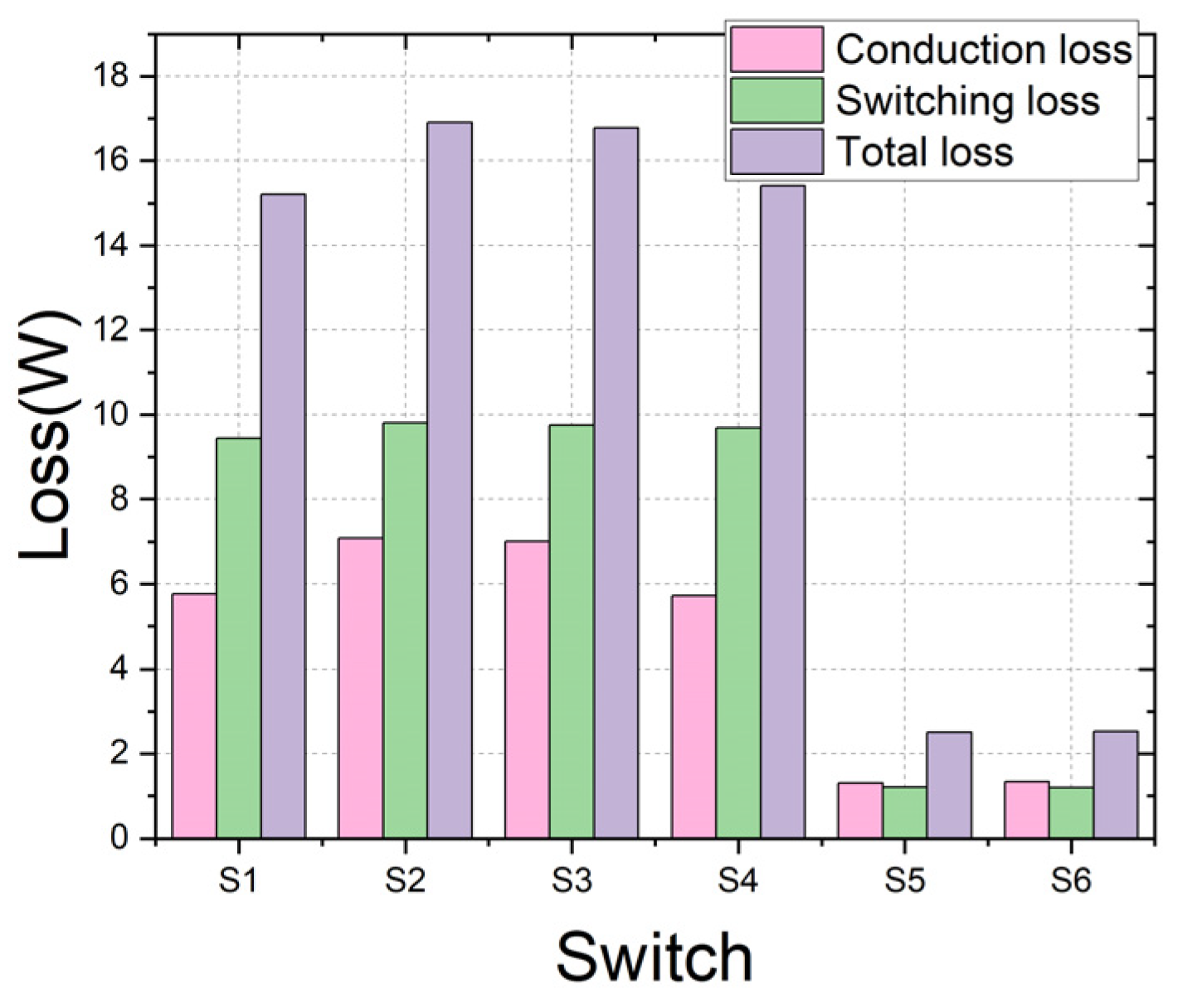
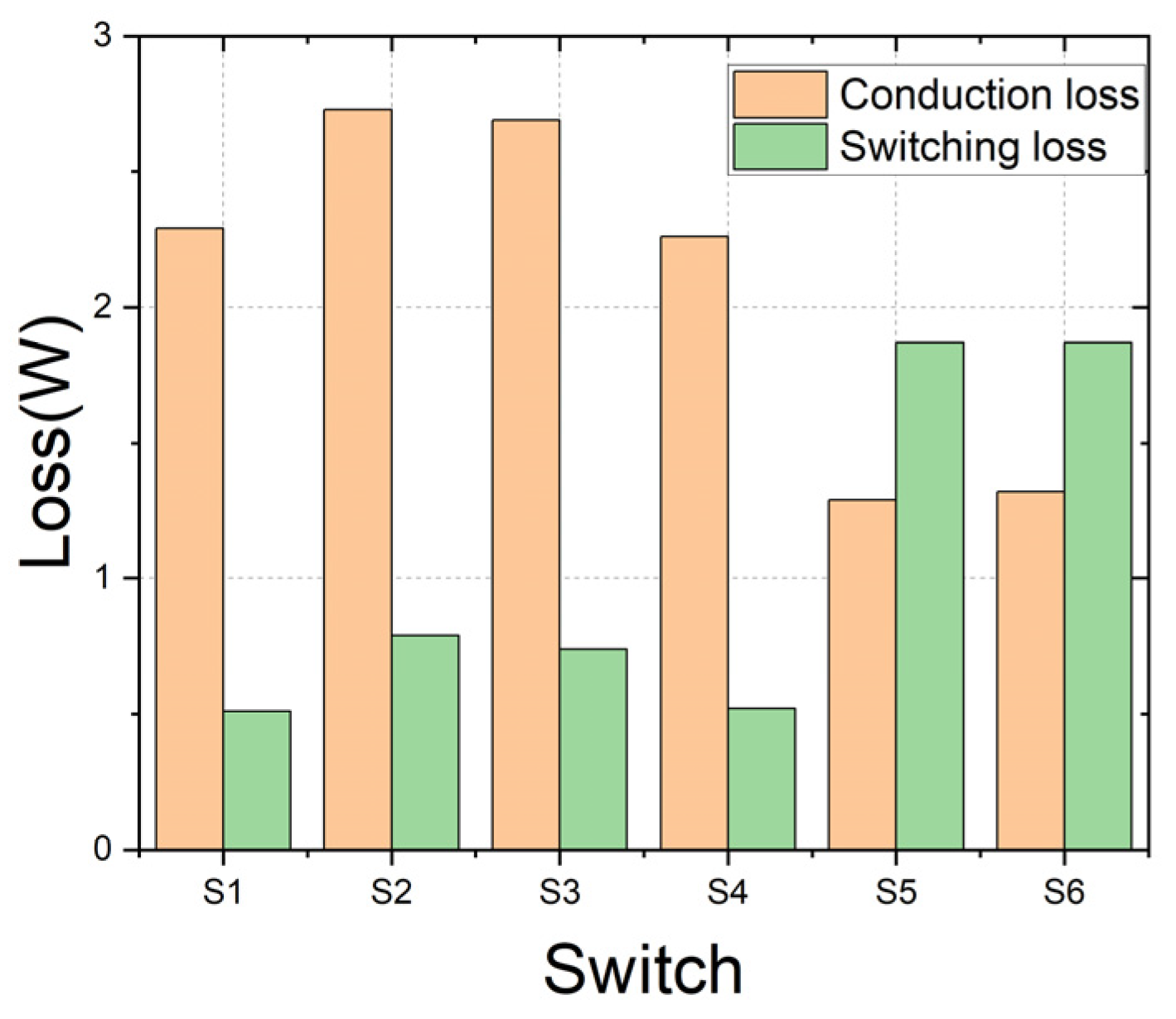
3.1. Analysis of Loss Distribution

Due to the symmetric structure of the ANPC inverter’s three bridge arms, loss analysis is performed on the six switches that make up a single bridge arm. Using Si, SiC, or GaN materials, the total losses of all switches—including conduction loss and switching loss—are determined and listed in Table 4.
Table 4 shows that the Si switch has the highest loss. In contrast, WBG and SiC devices can both significantly reduce switching loss and suppress the total loss, while GaN devices have the smallest total loss and only account for 20.4% of the loss from Si devices. Due to its low conduction resistance, it also has the lowest conduction loss (only 39.7% of Si devices and 51% of SiC devices).
However, WBG switches are more expensive and harder to market. To balance the loss and cost, it is, therefore, necessary to examine the loss distribution of a single bridge arm and suggest an improved structure. Figure 15 displays the loss distribution of every switch in the bridge arm using Si devices as examples.
Figure 15 reveals that losses come from the four switches, S1, S2, S3, and S4. S5 and S6 are connected to the neutral point; therefore, the loss is minimal. Meanwhile, the switching loss is the most significant part of the overall losses, and WBG devices outperform Si switches in this respect [48].

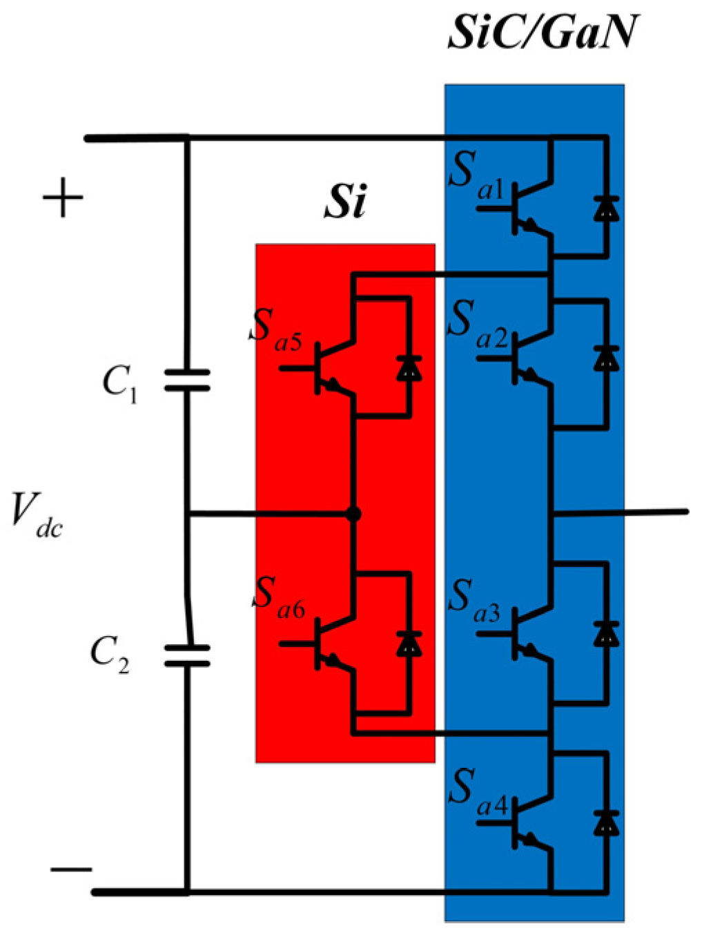
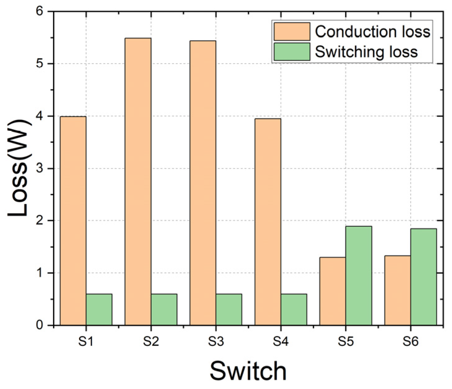
3.2. Design of Hybrid Structure

It is evident from the loss distribution study that substituting WBG devices for S1, S2, S3, and S4 switches can significantly reduce loss since WBG devices have smaller reverse recovery currents and reverse recovery times and can operate at higher switching frequencies with extremely low switching losses. This hybrid structure is shown in Figure 16.
As shown in Figure 17 and Figure 18, this design includes two hybrid structures of Si/SiC and Si/GaN, for which a loss analysis is conducted. Table 5 shows the precise loss and cost comparison between the single-device structure and the hybrid structure.
According to Table 5, the conduction loss and switching loss are significantly reduced for the Si/SiC hybrid structure, with the four switches’ switching losses being minimized to less than 1 W. The Si/GaN hybrid structure is better. The conduction loss is only roughly half of the former, and the overall loss is only 18.88 W. Its loss is even less than that of structure using SiC only, and it is second only to the scheme applying the hybrid structure to GaN only. This hybrid structure costs USD 189.44 for one arm, which is USD 83.68 and USD 64.96 less compared to all SiC or GaN devices, respectively. Consequently, the Si/GaN hybrid structure represents a good trade-off between cost and loss.

4. Conclusions and Future Work

This paper has investigated a PSM controller for the ANPC inverter, combining the passive control and SMC to improve the system performance in the presence of grid load changes. Three different control strategies were compared. Simulation results show that the PSM controller achieved desirable dynamic and steady-state performances in response to disruptions to the power grid’s operation conditions. Based on this, the ANPC inverter losses have then been investigated, and a hybrid Si/GaN structure for ANPC has been designed to strike a good trade-off between losses and costs. In this paper, we assume the load is balanced for the simplicity of analysis. It is, however, quite common that the load may become imbalanced in distribution networks, and an imbalanced load will cause power quality issues and impact the economic operation of distribution networks. Therefore, our future work will consider the imbalanced load conditions in the controller design. Furthermore, we have only conducted simulation verifications of the proposed control method, but we will also perform experimental verifications in our future work.

Author Contributions

Conceptualization, Y.Z.; methodology, Y.Z.; validation, Y.Z.; formal analysis, Y.Z.; writing—original draft preparation, Y.Z.; writing—review and editing, Y.Z., K.L., L.Z.; supervision, K.L. and L.Z.; project administration, K.L. All authors have read and agreed to the published version of the manuscript.

Funding

This research received no external funding.

Data Availability Statement

The original contributions presented in the study are included in the article, further inquiries can be directed to the corresponding author.

Acknowledgments

Yifei Zhang would like to thank the China Scholarship Council for the financial support for his PhD study.

Conflicts of Interest

The authors declare no conflicts of interest.

References

  1. Yao, H.; Yan, Y.; Shi, T. A novel SVPWM scheme for field-oriented vector-controlled PMSM drive system fed by cascaded H-bridge inverter. IEEE Trans. Power Electron. 2021, 36, 8988–9000. [Google Scholar] [CrossRef]
  2. Qanbari, T.; Tousi, B. Single-source three-phase multilevel inverter assembled by three-phase two-level inverter and two single-phase cascaded H-bridge inverters. IEEE Trans. Power Electron. 2020, 36, 5204–5212. [Google Scholar] [CrossRef]
  3. Shahabadini, M.; Moeini, N.; Bahrami-Fard, M.; Iman-Eini, H. Heric-based cascaded h-bridge inverter for leakage current suppression in pv systems. IEEE Trans. Power Electron. 2022, 38, 4005–4014. [Google Scholar] [CrossRef]
  4. Chen, M.; Loh, P.C. A dual-boost H-bridge inverter with common ground for photovoltaic interfacing. IEEE Trans. Ind. Electron. 2020, 68, 9515–9526. [Google Scholar] [CrossRef]
  5. Fang, J.; Blaabjerg, F.; Liu, S.; Goetz, S.M. A review of multilevel converters with parallel connectivity. IEEE Trans. Power Electron. 2021, 36, 12468–12489. [Google Scholar] [CrossRef]
  6. Perez, M.A.; Ceballos, S.; Konstantinou, G.; Pou, J.; Aguilera, R.P. Modular multilevel converters: Recent achievements and challenges. IEEE Open J. Ind. Electron. Soc. 2021, 2, 224–239. [Google Scholar] [CrossRef]
  7. Alatai, S.; Salem, M.; Ishak, D.; Das, H.S.; Nazari, M.A.; Bughneda, A.; Kamarol, M. A review on state-of-the-art power converters: Bidirectional, resonant, multilevel converters and their derivatives. Appl. Sci. 2021, 11, 10172. [Google Scholar] [CrossRef]
  8. Xu, S.; Huang, W.; Wang, H.; Zheng, W.; Wang, J.; Chai, Y.; Ma, M. A simultaneous diagnosis method for power switch and current sensor faults in grid-connected three-level NPC inverters. IEEE Trans. Power Electron. 2022, 38, 1104–1118. [Google Scholar] [CrossRef]
  9. Khan, A.A.; Khan, U.A.; Ahmed, H.F.; Cha, H.; Ahmed, S.A. Improved NPC inverters without short-circuit and dead-time issues. IEEE Trans. Power Electron. 2021, 37, 2180–2190. [Google Scholar] [CrossRef]
  10. Tcai, A.; Kwon, Y.; Pugliese, S.; Liserre, M. Reduction of the circulating current among parallel NPC inverters. IEEE Trans. Power Electron. 2021, 36, 12504–12514. [Google Scholar] [CrossRef]
  11. Wang, K.; Zheng, Z.; Xu, L.; Li, Y. Neutral-point voltage balancing method for five-level NPC inverters based on carrier-overlapped PWM. IEEE Trans. Power Electron. 2020, 36, 1428–1440. [Google Scholar] [CrossRef]
  12. Choi, U.M.; Ryu, T. Comparative evaluation of efficiency and reliability of single-phase five-level NPC inverters for photovoltaic systems. IEEE Access 2021, 9, 120638–120651. [Google Scholar] [CrossRef]
  13. Sathik, M.J.; Almakhles, D.J.; Sandeep, N.; Siddique, M.D. Experimental validation of new self-voltage balanced 9L-ANPC inverter for photovoltaic applications. Sci. Rep. 2021, 11, 5067. [Google Scholar] [CrossRef] [PubMed]
  14. Hakami, S.S.; Halabi, L.M.; Lee, K.B. Dual-carrier-based PWM method for DC-link capacitor lifetime extension in three-level hybrid ANPC inverters. IEEE Trans. Ind. Electron. 2022, 70, 3303–3314. [Google Scholar] [CrossRef]
  15. Song, J.; Chu, E.; Sun, Q. An Improved Auxiliary Resonant Pole TNPC Inverter and Its Modulation Strategy. IEEE Trans. Power Electron. 2024, 39, 9765–9776. [Google Scholar] [CrossRef]
  16. Muduli, U.R.; Behera, R.K. A modified high gain boost tnpc inverter with neutral point balancing for three-phase induction motor driven electric vehicle. In Proceedings of the 2020 IEEE International Conference on Power Electronics, Drives and Energy Systems (PEDES), Jaipur, India, 16–19 December 2020; IEEE: Piscataway, NJ, USA, 2020. [Google Scholar]
  17. Roy, P.; Banerjee, A. A study on performance parameters of three-level T-type inverter based PMSM drives for electric vehicles applications. Electr. Eng. 2024, 106, 1121–1134. [Google Scholar] [CrossRef]
  18. Guo, F.; Ma, Z.; Diao, F.; Cao, H.; Zhao, Y. Carrier-Based Space-Vector Coordinate-Shifted DPWM Strategy for Three-Level T-type NPC Inverters in Electric Aircraft Propulsion Applications. In Proceedings of the 2024 IEEE Applied Power Electronics Conference and Exposition (APEC), Long Beach, CA, USA, 25–29 February 2024; IEEE: Piscataway, NJ, USA, 2024. [Google Scholar]
  19. Hou, L.; Ma, Z.; Li, H.; Qiu, C.; Wang, K.; Zheng, Z. Research on Fault Tolerant Control Method of Three-Level TNPC Inverter. In Proceedings of the 2023 26th International Conference on Electrical Machines and Systems (ICEMS), Zhuhai, China, 5–8 November 2023; IEEE: Piscataway, NJ, USA, 2023. [Google Scholar]
  20. Song, W.; Saeed, M.S.R.; Yu, B.; Li, J.; Guo, Y. Model predictive current control with reduced complexity for five-phase three-level NPC voltage-source inverters. IEEE Trans. Transp. Electrif. 2021, 8, 1906–1917. [Google Scholar] [CrossRef]
  21. Khoshkbar-Sadigh, A.; Naderi, R.; Dargahi, V.; Corzine, K. Thermal and performance comparison of active neutral-point-clamped (anpc) and dual flyingcapacitor anpc (dfc-anpc) inverters. In Proceedings of the 2019 IEEE Energy Conversion Congress and Exposition (ECCE), Baltimore, MD, USA, 29 September–3 October 2019; IEEE: Piscataway, NJ, USA, 2019; pp. 5522–5528. [Google Scholar]
  22. Li, J.; Huang, A.Q.; Liang, Z.; Bhattacharya, S. Analysis and design of active NPC (ANPC) inverters for fault-tolerant operation of high-power electrical drives. IEEE Trans. Power Electron. 2011, 27, 519–533. [Google Scholar] [CrossRef]
  23. He, J.; Zhang, D.; Pan, D. PWM strategy for MW-scale “SiC+ Si” ANPC converter in aircraft propulsion applications. IEEE Trans. Ind. Appl. 2020, 57, 3077–3086. [Google Scholar] [CrossRef]
  24. Dargahi, V.; Corzine, K.A.; Enslin, J.H.; Rodríguez, J.; Blaabjerg, F. Improved active-neutral-point-clamped (I-ANPC) multilevel converter: Fundamental circuit topology, innovative modulation technique, and experimental validation. In Proceedings of the 2018 IEEE Power and Energy Conference at Illinois (PECI), Champaign, IL, USA, 22–23 February 2018; IEEE: Piscataway, NJ, USA, 2018; pp. 1–8. [Google Scholar]
  25. Hwang, J.H.; Halabi, L.M.; Ko, Y.; Lee, K.B. Lifetime-based fault tolerant strategy for three-level hybrid ANPC inverters. J. Power Electron. 2023, 23, 363–373. [Google Scholar] [CrossRef]
  26. Humada, A.M.; Darweesh, S.Y.; Mohammed, K.G.; Kamil, M.; Mohammed, S.F.; Kasim, N.K.; Tahseen, T.A.; Awad, O.I.; Mekhilef, S. Modeling of PV system and parameter extraction based on experimental data: Review and investigation. Sol. Energy 2020, 199, 742–760. [Google Scholar] [CrossRef]
  27. Hamzat, A.K.; Sahin, A.Z.; Omisanya, M.I.; Alhems, L.M. Advances in PV and PVT cooling technologies: A review. Sustain. Energy Technol. Assess. 2021, 47, 101360. [Google Scholar] [CrossRef]
  28. Wang, Y.; Zou, R.; Liu, F.; Zhang, L.; Liu, Q. A review of wind speed and wind power forecasting with deep neural networks. Appl. Energy 2021, 304, 117766. [Google Scholar] [CrossRef]
  29. Oyekale, J.; Petrollese, M.; Tola, V.; Cau, G. Impacts of renewable energy resources on effectiveness of grid-integrated systems: Succinct review of current challenges and potential solution strategies. Energies 2020, 13, 4856. [Google Scholar] [CrossRef]
  30. Li, G.; Chen, Y.; Luo, A.; Wang, Y. An inertia phase locked loop for suppressing sub-synchronous resonance of renewable energy generation system under weak grid. IEEE Trans. Power Syst. 2021, 36, 4621–4631. [Google Scholar] [CrossRef]
  31. Naqvi, S.B.Q.; Singh, B. A PV-battery system resilient to weak grid conditions with regulated power injection and grid supportive features. IEEE Trans. Sustain. Energy 2022, 13, 1408–1419. [Google Scholar] [CrossRef]
  32. Yang, D.; Ruan, X.; Wu, H. Impedance shaping of the grid-connected inverter with LCL filter to improve its adaptability to the weak grid condition. IEEE Trans. Power Electron. 2014, 29, 5795–5805. [Google Scholar] [CrossRef]
  33. Ashabani, M.; Mohamed, Y.A.R.I. Integrating VSCs to weak grids by nonlinear power damping controller with self-synchronization capability. IEEE Trans. Power Syst. 2013, 29, 805–814. [Google Scholar] [CrossRef]
  34. Pal, S.; Roy, A.; Shivakumara, P.; Pal, U. Adapting a swin transformer for license plate number and text detection in drone images. Artif. Intell. Appl. 2023, 1, 145–154. [Google Scholar] [CrossRef]
  35. Helali, R.G.M. An Exploratory Study of Factors Affecting Research Productivity in Higher Educational Institutes Using Regression and Deep Learning Techniques. Artif. Intell. Appl. 2022, 1, 23–26. [Google Scholar] [CrossRef]
  36. Yang, B.; Yu, T.; Shu, H.; Zhang, Y.; Chen, J.; Sang, Y.; Jiang, L. Passivity-based sliding-mode control design for optimal power extraction of a PMSG based variable speed wind turbine. Renew. Energy 2018, 119, 577–589. [Google Scholar] [CrossRef]
  37. Shunchao, K.E.; Miao, Z.H.U.; Yang, C.; Zheng, C.; Cungang, H.U. Passive sliding mode variable structure control for mmc-upfc. In Proceedings of the 2019 IEEE Innovative Smart Grid Technologies-Asia (ISGT Asia), Chengdu, China, 21–24 May 2019; IEEE: Piscataway, NJ, USA, 2019; pp. 2184–2189. [Google Scholar]
  38. Zhang, L.; Zheng, Z.; Lou, X. A review of WBG and Si devices hybrid applications. Chin. J. Electr. Eng. 2021, 7, 1–20. [Google Scholar] [CrossRef]
  39. Zhang, L.; Lou, X.; Li, C.; Wu, F.; Gu, Y.; Chen, G.; Xu, D. Evaluation of different Si/SiC hybrid three-level active NPC inverters for high power density. IEEE Trans. Power Electron. 2019, 35, 8224–8236. [Google Scholar] [CrossRef]
  40. Feng, Z.; Zhang, X.; Wang, J.; Yu, S. A high-efficiency three-level ANPC inverter based on hybrid SiC and Si devices. Energies 2020, 13, 1159. [Google Scholar] [CrossRef]
  41. Balaji, P.S.; Karthik SelvaKumar, K. Applications of nonlinearity in passive vibration control: A review. J. Vib. Eng. Technol. 2021, 9, 183–213. [Google Scholar] [CrossRef]
  42. Udabe, A.; Baraia-Etxaburu, I.; Diez, D.G. Gallium nitride power devices: A state of the art review. IEEE Access 2023, 11, 48628–48650. [Google Scholar] [CrossRef]
  43. Ravinchandra, K.; Freddy, T.K.S.; Thiruchelvam, V. Review of electrical characteristics for wide bandgap power devices. In Proceedings of the 2021 IEEE 12th Energy Conversion Congress & Exposition-Asia (ECCE-Asia), Singapore, 24–27 May 2021; IEEE: Piscataway, NJ, USA, 2021. [Google Scholar]
  44. Chen, J.; Du, X.; Luo, Q.; Zhang, X.; Sun, P.; Zhou, L. A review of switching oscillations of wide bandgap semiconductor devices. IEEE Trans. Power Electron. 2020, 35, 13182–13199. [Google Scholar] [CrossRef]
  45. Infineon IGW60T120 Trenchstop Si IGBT Datasheet. Available online: http://www.infineon.com/dgdl/Infineon-IGW60T120-DS-v02_04 (accessed on 11 February 2024).
  46. Cree (Wolfspeed) C2M0040120D SiC Power MOSFET Datasheet. Available online: http://www.wolfspeed.com/media/downloads/165/C2M0040120D.pdf (accessed on 15 February 2024).
  47. GaN Systems GS-065-060 GaN Power Transistor. Available online: https://gansystems.com/gan-transistors/gs-065-060-5-t-a/ (accessed on 11 February 2024).
  48. Zhang, Y.; Li, K.; Zhang, L. Loss Analysis of ANPC Inverters with Hybrid Si and WBG Devices. In Proceedings of the 2024 International Conference on Life System Modeling and Simulation (LSMS2024) and 2024 International Conference on Intelligent Computing for Sustainable Energy and Environment (ICSEE2024), Suzhou, China, 20 December–15 September 2024. [Google Scholar]
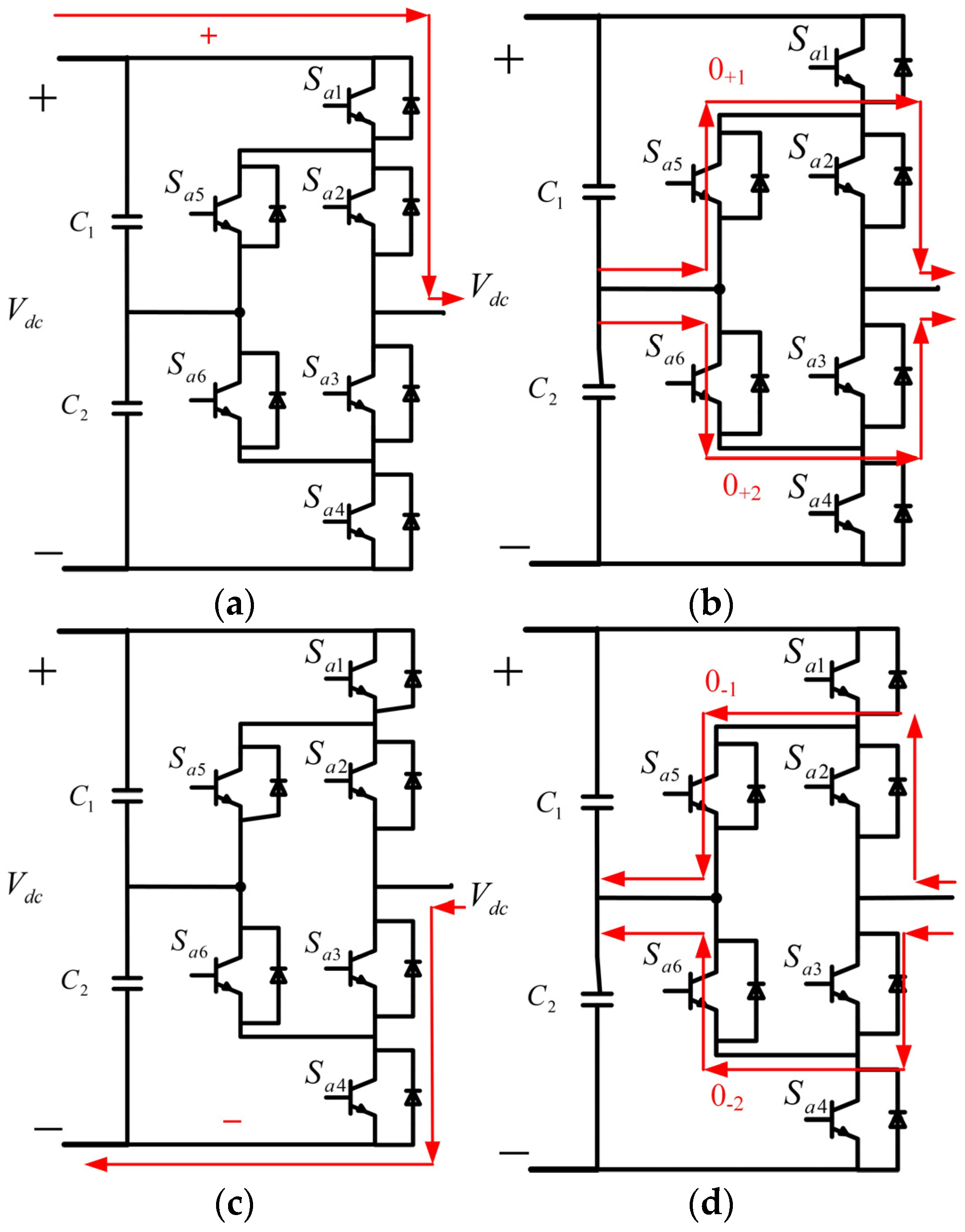
Figure 1. A three-phase hybrid ANPC grid-tied inverter circuit.
Energies 17 03655 g001
Figure 2. PS-PWM scheme. Blue and red triangle waves are two carrier waves with a 180° phase difference; Black sine wave is reference wave.
Energies 17 03655 g002
Figure 3. States of PS-PWM control: (a) positive cycle; (b) two ZVS for positive state; (c) negative cycle; (d) two ZVS for negative state.
Energies 17 03655 g003
Figure 4. Switching states of PS-SWM control. (a) positive cycle; (b) negative cycle. Blue and red triangle waves are two carrier waves with a 180° phase difference; Black sine wave is reference wave. The red square wave represents the PWM waveform in the positive cycle while the blue one represents it in the negative cycle.
Energies 17 03655 g004
Figure 5. Block diagram of the grid-tied inverter equivalent circuit model.
Energies 17 03655 g005
Figure 6. Block diagram of passive controller.
Energies 17 03655 g006
Figure 7. Block diagram of PSM controller.
Energies 17 03655 g007
Figure 8. Diagram of the system.
Energies 17 03655 g008
Figure 9. Passive control with load mutation. The red, blue, and black lines are three phase current waves.
Energies 17 03655 g009
Figure 10. PSM with load mutation.
Energies 17 03655 g010
Figure 11. SMC with load mutation.
Energies 17 03655 g011
Figure 12. Passive control with different reference currents.
Energies 17 03655 g012
Figure 13. PSM with different reference currents.
Energies 17 03655 g013
Figure 14. SMC with different reference currents.
Energies 17 03655 g014
Figure 15. Loss distribution of switches.
Energies 17 03655 g015
Figure 16. Hybrid structure.
Energies 17 03655 g016
Figure 17. Si/SiC hybrid structure.
Energies 17 03655 g017
Figure 18. Si/GaN hybrid structure.
Energies 17 03655 g018
Table 1. Switching states of ANPC inverter.
StatesSa1Sa2Sa3Sa4Sa5Sa6
Positiveononoffoffoffon
0+1offonoffoffonoff
0+2onoffonoffoffon
0−1offonoffononoff
0−2offoffonoffoffon
Negativeoffoffonononoff
Table 2. Parameters of the system.
ParametersValueParametersValue
Input voltage, Vdc800 VGrid-side inductance, Lgi1.58 mH
Input capacitors, C1, C25 mFFilter capacitors, Cf0.1 mF
Filter inductance, Li3 mHGrid voltage, ugi220 V
Switching frequency, fs10,000 HzResistance of inductance, Ri1 mΩ
Grid-side resistance, Rg0.8929 Ω
Table 3. Parameters of the controllers.
ControllerParametersValue
Passive controllerR0.44645
Ra1, Ra2100
SMCλ1, λ247
R0.44645
k1, k220,000
PSM controllerRa1, Ra250
k1, k2100
R0.44645
λ1, λ213,100
Table 4. Loss comparison among different devices.
DevicesSiSiCGaN
Conduction loss (W)28.2421.9711.22
Switching loss (W)41.082.4092.9
Total loss (W)69.3224.38914.12
Table 5. Losses comparison among different structures.
DevicesSiSiCGaNSi/SiCSi/GaN
Conduction loss (W)28.2421.9711.2221.512.58
Switching loss (W)41.082.4092.96.146.3
Total loss (W)69.3224.38914.1227.6418.88
Cost (USD)59.52273.12254.4201.92189.44
Power (W)10,492.0410,626.8310,657.6410,617.0810,643.36
Disclaimer/Publisher’s Note: The statements, opinions and data contained in all publications are solely those of the individual author(s) and contributor(s) and not of MDPI and/or the editor(s). MDPI and/or the editor(s) disclaim responsibility for any injury to people or property resulting from any ideas, methods, instructions or products referred to in the content.

