Article

A Hybrid Commutation Technique for Reducing Zero-Crossing Distortion in a Sliding Mode Controller for Single-Phase Grid-Tied Full-Bridge Inverters

by
Mario Andrés Bolaños-Navarrete
*,
Juan David Bastidas-Rodríguez
and
Gustavo Osorio
Facultad de Ingeniería y Arquitectura, Universidad Nacional de Colombia, Manizales 170003, Colombia
*
Author to whom correspondence should be addressed.
Energies 2024, 17(15), 3671; https://doi.org/10.3390/en17153671
Submission received: 11 June 2024 / Revised: 15 July 2024 / Accepted: 17 July 2024 / Published: 25 July 2024
(This article belongs to the Section F: Electrical Engineering)

Abstract

:
This paper presents a single-phase Full-Bridge (FB) inverter with a hybrid commutation technique designed to reduce the harmonic distortion caused by the loss of the controller capability around the zero-crossing point in the unipolar commutation region. The hybrid modulation changes from unipolar to bipolar commutation under the loss of the reference control, improving the robustness and efficiency of the method. The commutation technique improves the switching performance and reduces the switching losses. Simulation models are developed in MATLAB/Simulink R2023b to evaluate their performance under different operating conditions. The results show that the proposed commutation technique can achieve high efficiency, low total harmonic distortion (THD), and fast dynamic response. The experimental implementation of sliding mode control (SMC) implemented in an STM32 microcontroller confirms that the hybrid commutation technique can reduce the THD by 0.96 percentage points for local (off-grid) loads and up to 2.45 in an industrial grid-tie network, compared with unipolar commutation. These findings highlight the potential of the proposed modulation technique for applications like solar panels and offer crucial insights for ongoing research and development in this field.

1. Introduction

Single-phase Full-Bridge (FB) inverters are crucial components in a variety of power electronic applications, such as motor drives and uninterruptible power supplies (UPS), and increasingly used in energy systems. In these latter applications, FB inverters play a key role in cases where it is necessary to convert direct current (DC) to alternating current (AC) that is compatible with the load or the electrical grid [1,2]. In particular, FB inverter topology is highly valued for its efficiency, robust power capacity, reliability, and versatility. FB inverters operate through two main commutation methods: unipolar and bipolar [3]. Bipolar commutation is generally preferred for its simplicity, design flexibility, and robust stability [4]. On the other hand, unipolar commutation is favored in scenarios where reducing the filter size and minimizing switching losses are priorities. These reductions are achieved by decreasing the number of switch transitions per cycle, which enhances the overall efficiency [5]. However, unipolar commutation presents several critical challenges; it is particularly susceptible to zero-crossing distortion (ZCD), which significantly affects the quality of the output current [6,7,8]. This issue increases the total harmonic distortion (THD) and affects tasks such as reactive power injection [6].
Zero-crossing distortion is a major issue in unipolar commutation for current control, regardless of the control strategy implemented. This distortion occurs when the slope of the actual current is less than the reference current slope in the vicinity of zero-crossing points, leading to more low-frequency harmonics, which harm inverter performance [9]. Several methods have been proposed to address this problem, for example, adjusting the hysteresis band width, adding dead bands at zero-crossing points, and using phase angle compensation to correct the current trajectory [9,10,11]. Advancements in correcting ZCD have introduced techniques such as mixed modulation, which combines the advantages of bipolar and unipolar commutations to reduce the THD. A promising development has involved decoupling the traditional single-phase FB inverter into two independent half-bridge units, eliminating ZCD issues without substantial hardware overhauls [12]. However, implementing this control is complex because it requires precise predictions of the common-mode voltage ( u M N ) and heavily relies on accurate knowledge of circuit parameters.
Other approaches include combining unipolar and bipolar commutation and the use of the discontinuous conduction mode operation with elaborated control strategies [13,14]. In [13], the authors propose to operate the converter in unipolar commutation when the grid voltage is greater than half of the DC bus voltage; consequently, the FB inverter operates in bipolar commutation around the zero-crossing region. However, the authors do not provide a clear justification for selecting this criterion. Furthermore, the strategy to switch from unipolar to bipolar commutation proposed in [14] depends on the angles of the grid voltage and the injected current; however, it is not clearly explained. Additionally, the system stability of the FB inverter with the proposed control systems is not analyzed in [13] or in [14]. In [6], the authors use a PWM technique to generate the switching signals along with a strategy for switching between unipolar and bipolar commutation. The inverter considered in the study is designed to operate with power factors other than one; therefore, default commutation is unipolar, switching to bipolar when the injected current and grid voltage have opposite signs. However, the authors did not perform stability analysis. Even more, the inverter topology has an additional switch when compared with the FB topology. In the literature, other approaches to reduce ZCD in FB inverters can be found. Some focus on complex control techniques, such as state trajectory prediction, which can reduce ZCD and improve the dynamic response of the inverter [15]. Other authors propose using two power converters cooperating [16], different commutation strategies [17], or additional switches with complex control strategies [18].
Despite all these innovations, the strategies do not fully consider the critical transition points between the commutation modes, which is essential to optimize performance and reduce distortion [19,20]. Moreover, although these developments represent significant improvements, they often require complex control strategies or hardware adjustments, which pose challenges to practical implementation [21,22,23,24]. To address these issues, this paper proposes a hybrid commutation technique that merges the strengths of both unipolar and bipolar methods to effectively mitigate ZCD with a more straightforward and adaptable control approach. The main contribution of this paper lies in the development and analysis of a hybrid modulation technique designed to effectively mitigate zero-crossing distortion (ZCD) for an FB inverter with a sliding mode controller. This approach integrates a detailed analysis of SMC, specifically the transversality and reachability conditions. In doing so, it allows for the precise calculation of the critical angles at which control is lost, providing a solid foundation for the control strategy. Analytical results obtained from this paper offer specific guidelines for the design of a hybrid controller capable of transitioning between unipolar and bipolar commutation to mitigate the issues associated with ZCD. Unlike methods that rely on complex modulation algorithms or control strategies, ours favors simplicity and intuitiveness, ensuring superior functionality. Our technique does not require hardware modifications, making it highly adaptable and suitable for a broad spectrum of power electronic systems and applications. The inherent adaptability of this technique also greatly simplifies the tuning and optimization processes. This reduction in complexity significantly reduces the time and effort required for optimization, making it an attractive option for existing hardware designs. The implementation in the STM32G474RE microcontroller, taking advantage of high-frequency timers and built-in analog comparators, confirms the high performance and practical usability of this method.
This paper is structured as follows: Section 2 establishes the groundwork by explaining the operational principles of the Full-Bridge inverter, focusing on unipolar, bipolar, and hybrid commutation methods. Section 3 introduces the proposed control strategy, exploring the analysis of the SMC of the inverter, which includes assessing its stability and offering design guidelines. Section 4 presents simulation and experimental results that demonstrate the efficacy of the proposed method, specifically in terms of ZCD mitigation, THD reduction, and dynamic response. This paper concludes with Section 5, summarizing the key findings.

2. Full-Bridge Inverter Operation

The grid-connected Full-Bridge inverter with an LCL filter used in this paper is presented in Figure 1, where V B represents the DC bus the inverter is connected to; v G represents the voltage imposed by the grid; S p , S n , S n e , and S p e are the switches; and U p , U n , U n e , and U p e are the corresponding switching signals, and D p , D n , D n e , and D p e are the diodes associated. Moreover, the LCL filter is composed of an inductor L, a capacitor C, and a choke filter inductor L f , while R L and R f are the parasitic resistances of L and L f , respectively.
The output voltage signal and the modulation for the three operational modes of the Full-Bridge (FB) inverter are presented in Figure 2. The first mode utilizes the FB topology with unipolar commutation (FB-U) (Figure 2a). The second mode employs the FB topology with its conventional bipolar commutation (FB-B) (Figure 2b), and the third one combines the unipolar and bipolar commutation (Figure 2c).
The dynamic equations that describe the operation of the FB inverter for all operating modes are introduced in (1), where i ( t ) and i F ( t ) are the currents of L and L f , respectively; v ( t ) is the voltage of the capacitor; and u ( t ) is the control signal, which would depend on each mode as described next.
d i ( t ) d t = 1 L R L i ( t ) v ( t ) + u ( t ) V B d v ( t ) d t = 1 C i ( t ) i F ( t ) d i F ( t ) d t = 1 L F v ( t ) R F i F ( t ) v G ( t )

2.1. Inverter Operation with Unipolar Commutation (FB-U)

In unipolar commutation, one switch remains ON during the half cycle of v G ( S p e or S n e ), and the other commutates according to the switching signal determined by the controller ( S p or S n ). Therefore, there are fewer commutation losses in S p e and S p e [9]. The FB-U inverter has two operating modes: Mode 1 and Mode 2 accord to positive and negative semi-cycles of v G , respectively.
In Mode 1, the operating switches are S p and S p e , where S p e is ON and S p commutates (see Figure 3). On the one hand, when S p is ON, i L (red dotted line) flows through V B , S p , and S p e to charge L, C, and L f , as shown in Figure 3a. On the other hand, when S p is OFF, i L flows through S p e and the diode of S n to discharge L, C, and L f (see Figure 3b).
Mode 2 is illustrated in Figure 4. In this mode, S n commutates and S n e remains ON. When S n is ON, i L (blue dotted line) flows through V B , S n e , and S n to charge L, C, and L f ; and when S n is OFF, i L flows through S n e and the diode of S p to discharge L, C, and L f .
In operation, as a unipolar inverter, the control signal u ( t ) is defined as shown in (2) and (3) when operating in Mode 1 and Mode 2, respectively. These equations also explain the states of the four switches for each value of the control signal.
u ( t ) = 1 ( U p = O N U n e = O F F U n = O F F U p e = O N ) 0 ( U p = O F F U n e = O F F U n = O F F U p e = O N )
u ( t ) = 0 ( U p = O F F U n e = O N U n = O F F U p e = O F F ) 1 ( U p = O F F U n e = O N U n = O N U p e = O F F )

2.2. Inverter Operation with Bipolar Commutation (FB-B)

In this operation (Mode 3), the four switches operate during the positive and negative half cycles of v G ; hence, there are two possible states for the switches, as shown in Figure 5. When S p and S p e are ON ( S n and S n e are OFF), i L (green dotted line) flows through V B , S p , and S p e . If v G is positive, then L, C, and L f are charged; otherwise, they are discharged. A similar analysis can be performed when S n and S n e are ON ( S p and S p e are OFF), where L, C, and L f are charged if v G is negative and discharged otherwise.
It is important to note that all the switches operate at the same frequency with this modulation; hence, the commutation losses are greater regarding unipolar modulation [9]. The control signal u ( t ) and the switch states are defined as shown in (4).
u ( t ) = 1 ( U p = O F F U n e = O N U n = O F F U p e = O F F ) 1 ( U p = O F F U n e = O N U n = O N U p e = O F F )

2.3. Inverter Operation with Hybrid Commutation (FB-H)

In the hybrid commutation mode, the bipolar and unipolar methods are combined. The FB-U mode is enabled most of the time, while the FB-B mode is enabled only around zero-crossing points. The possible operation modes for hybrid commutation follow the modes described for FB-U and FB-B in Equations (2)–(4). However, to manage the transition between the two commutations, a 2:1 multiplexer is used, and the decision on where to switch will be further studied in the following section.

3. FB Inverter Control Strategy

FB-U and FB-B operations offer distinct advantages and drawbacks. On the one hand, an FB-U inverter reduces the switching losses since only one transistor operates at high frequency, while a second transistor remains active [4,25]. However, this method presents control problems in the zero-crossing region increasing the THD.
On the other hand, when the inverter operates as FB-B, stability conditions are fulfilled even around zero crossing of i ( t ) . Nevertheless, this mode requires two transistors operating at high frequency, which increases commutation losses and reduces the system overall efficiency and lifespan [26].
The hybrid strategy aims to combine the strengths of both operating modes and mitigate their drawbacks. This method alternates between FB-U and FB-B modes; thus, the inverter predominantly operates in FB-U mode to reduce switching losses and changes to FB-B mode only in the time windows when FB-U cannot guarantee the system stability. This approach improves inverter efficiency and reliability, guaranteeing the system stability.
This section begins by presenting the control scheme. Following that, a thorough analysis of the proposed sliding mode control is provided to identify the optimal ranges for unipolar and bipolar commutations. This is followed by a subsection providing guidelines to recommend the correct choices for the design parameters.

3.1. Control Scheme Functionality

The control scheme for the Full-Bridge inverter, as presented in Figure 6, receives two measured signals: the inductor current i ( t ) and the grid voltage v G . Additionally, it utilizes three control parameters: the critical angle ( ϕ ), which would be used to switch from FB-U to FB-B and is deduced in the next subsection; the peak current reference ( i r p ); and the amplitude of the hysteresis band ( H ) . The functionality of the proposed control can be organized into three main blocks: operation mode, control strategy, and sliding mode control (SMC).
The operation mode block encompasses the three distinct operational modes of the inverter: FB-U operation during the positive half cycle ( F B U p ), FB-U operation during the negative half cycle ( F B U n ), and FB-B operation ( F B B ). These modes are mathematically represented by Equations (2)–(4), as detailed in Section 2. The block receives the control signal u from the SMC block and outputs the signals U p , U n , U p e , and U n e .
The hysteresis block generates the control signal u ( t ) by using two comparators and an SR flip-flop. This block takes the unitary sinusoidal signal from the Phase-Locked Loop (SPLL) and multiplies it by the peak current signal i r p to create a reference current ( i r e f ).
Moreover, the control strategy block receives the PLL output and the critical commutation angle ϕ to determine the appropriate inverter operation mode through a multiplexer “ M u x F B - U / F B - B ”. This block determines whether the inverter should operate in FB-U or FB-B mode by comparing the PLL output and the cosine of ϕ . This comparison ensures that the Full-Bridge mode is active only in the region where the reachability condition is not fulfilled by the FB-U mode. Additionally, when operating in FB-U mode, the sign of the PLL signal indicates whether the inverter is in the positive or negative half cycle, thus determining the FB-U operational mode between F B U p and F B U n .

3.2. Sliding Mode Control Analysis

The sliding mode theory is selected for the controller design due to its fast dynamic response, robustness to parameter variations, and simple implementation with analog or digital circuitry [25]. Compared with other reported controllers, such as boundary control, which is known for its higher efficiency, but is more complex to implement and tune, SMC is straightforward. Model predictive control (MPC) offers good optimization, but is computationally intensive and provides a narrower bandwidth, making SMC more efficient and practical. State-trajectory control requires detailed system modeling and precise measurements, increasing complexity and computational costs, whereas SMC effectively handles uncertainties with simpler implementation. Figure 6 introduces the proposed sliding mode controller for the FB with unipolar and bipolar commutations.
Compared with boundary control, which is reported to have higher efficiency but is more complex to implement and tune, SMC is straightforward [5]. Model predictive control (MPC) offers good optimization, but is computationally intensive and provides a narrower bandwidth, making SMC more efficient and practical. State-trajectory control requires detailed system modeling and precise measurements, increasing complexity and computational costs, whereas SMC effectively handles uncertainties with a simpler implementation [15].
This subsection begins by defining the sliding surface and then evaluating the conditions of transversality and reachability for all the operation modes of an FB inverter.

3.2.1. Sliding Mode Surface

The switching function (S) and the sliding surface ( Φ ) defined for the SMC of the Full-Bridge inverter are presented in (5) and (6), where i ( t ) is the current through L (see Figure 3), and i r ( t ) is the sinusoidal reference with amplitude I p and angular frequency w, as shown in (7). Additionally, i r ( t ) is in phase with v G ( t ) , which is defined as v G ( t ) = V p c o s ( ω t ) , where V p is the voltage amplitude and ω is the grid angular frequency. Hence, w is the same for both i r ( t ) and v G ( t ) . At this point, it is important to mention that i ( t ) = i F ( t ) in steady state, according to (1); therefore, controlling i ( t ) is possible to control the current injected into the grid.
S ( t ) = i ( t ) i r ( t )
Φ = { S ( t ) = 0 }
i r ( t ) = I p cos ( ω t )
The time derivative of S is introduced in (8), where u = [ 1 , 0 ] , u = [ 0 , 1 ] , and u = [ 1 , 1 ] when the FB operates in Mode 1 (i.e., v G ( t ) > 0 ), Mode 2 (i.e., v G ( t ) < 0 ), and Mode 3 (i.e., 0 < v G ( t ) < 0 ), respectively. This derivative is used to analyze the stability conditions of the SMC, which correspond to transversality and reachability [26].
d S ( t ) d t = R L i ( t ) + V B u v ( t ) L + I p ω sin ( ω t )

3.2.2. Transversality Condition

This condition evaluates the possibility of modifying the trajectories of the system with the two states of the control signal u. Therefore, it is necessary to calculate the derivative of d S / d t with respect to u, as shown in (9). This expression indicates a positive transversality considering that V B and L are positive; therefore, an increase in u produces an increment in d S / d t and vice versa.
d d S ( t ) d t d u = V B L
Taking into account the two operating modes of FB-U, the behavior of d S / d t is described below and is considered for the reachability analysis:
  • Mode 1: u = 1 then d S / d t > 0 and u = 0 then d S / d t < 0 ;
  • Mode 2: u = 0 then d S / d t > 0 and u = 1 then d S / d t < 0
For FB-B, only one mode is exhibited. A positive value of u leads to an increase in d S / d t and a negative value of u leads to a decrease in d S / d t .
  • Mode 3: u = 1 results in d S d t > 0 , while u = 1 leads to d S d t < 0

3.2.3. Reachability Condition

This condition evaluates the capacity of the system to reach the desired surface ( Φ = { S = 0 } ) when S > 0 and S < 0 , and it is described in (10) and (11) for Mode 1 and Mode 2 of FB-U, respectively.
lim S 0 d S d t > 0 u = 1 lim S 0 + d S d t < 0 u = 0
lim S 0 d S d t > 0 u = 0 lim S 0 + d S d t < 0 u = 1
For FB-B, the necessary condition to reach the desired surface Φ when S > 0 and S < 0 is defined in (12) as follows:
lim S 0 d S d t > 0 u = 1 lim S 0 + d S d t < 0 u = 1
Replacing (8) into (10) for u = 1 and (8) into (11) for u = 1 results in the same inequality shown in (13), which is valid for Mode 1, Mode 2, and Mode 3.
I p ω sin ( ω t ) + R L i ( t ) + V B v ( t ) L > 0
Moreover, assuming that the system is controlled in steady state, then i ( t ) = i r ( t ) = I p c o s ( ω t ) , and the average current through the capacitor is 0 A ; therefore, i ( t ) i F ( t ) , which can be used to define the average capacitor voltage, as shown in (14), where V c = V p + R F I p .
v ( t ) = ( V p + R F I p ) cos ω t = V c cos ω t
Now, solving V B from (13), it is possible to obtain (15), which indicates the restriction for V B when the inverter is operating with u = { 1 , 1 } . Take into account that such a restriction is a sinusoidal function; hence, (15) is met for any time if restriction (16) is fulfilled. It is important to note that this conditions ensures the reachability for bipolar commutation. That is, if the DC link voltage satisfies Equation (16), FB-B ensures control stability across all values of ω t . However, for unipolar commutation, this restriction is necessary (but not sufficient) to guarantee the reachability.
V B > ( R L I p + V p ) 2 + ( L I p ω ) 2 cos ω t + tan 1 L I P ω R L I p + V c
V B > ( R L I p + V p ) 2 + ( L I p ω ) 2
Furthermore, for unipolar commutation, replacing (8) with (10) and (11) for u = 0 results in the inequalities shown in (17), where the right and left sides of the inequalities apply to Mode 1 ( v G ( t ) > 0 V ) and Mode 2 ( v G ( t ) < 0 V ), respectively.
0 < I p ω sin ( ω t ) + R L i ( t ) v ( t ) L ; & I p ω sin ( ω t ) + R L i ( t ) v ( t ) L < 0
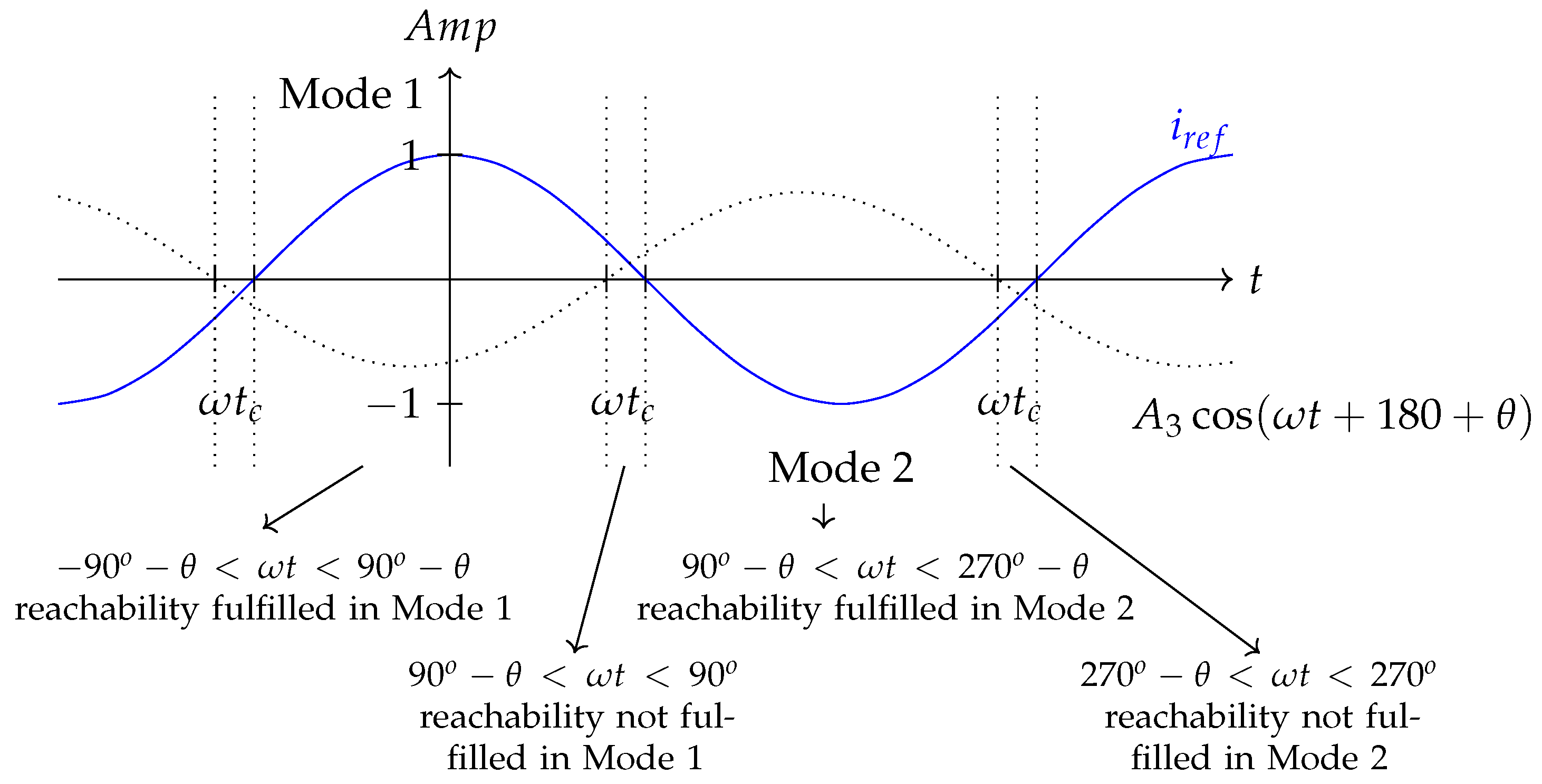
Now, assuming that the system is controlled in steady state (i.e., i ( t ) = i r ( t ) = I p c o s ( ω t ) and v ( t ) = V c c o s ( ω t ) ), it is possible to obtain (18), where the inequality on the right applies to Mode 1 ( v G ( t ) > 0 V ), while the inequality on the left applies to Mode 2 ( v G ( t ) < 0 V ). Writing (18) as a single cosine function results in (19), where A 1 = L I p ω , A 2 = R L I p + V c , A 3 = A 1 2 + A 2 2 , and θ = arctan A 1 A 2 .
0 < ( L I P ω ) sin ω t ( R L I p + V c ) c o s ω t ; & ( L I P ω ) sin ω t ( R L I p + V c ) c o s ω t < 0
0 < A 3 cos ( ω t + 180 + θ ) ; & A 3 cos ( ω t + 180 + θ ) < 0
From the right inequation of (19), it is possible to obtain a range of ω t where the reachability condition is fulfilled in Mode 1 ( v G ( t ) > 0 V ); such a range is introduced in (20). With a similar procedure, it is possible to define the range where the reachability condition is fulfilled in Mode 2 ( v G ( t ) > 0 V ), as shown in (21).
90 θ < ω t < 90 θ
90 θ < ω t < 270 θ
Figure 7 illustrates the condition (19) with the current reference i r e f . It shows the angles where the reachability condition is fulfilled, as given by (20) and (21). Consequently, there are two regions of ω t where reachability condition is not ensured, resulting in instability for the FB-U inverter with the proposed SMC. Those regions are defined in terms of critic values of ω t c , as shown in (22) and (23) for Mode 1 ( v G ( t ) > 0 V ) and Mode 2 ( v G ( t ) < 0 V ), respectively.
90 θ < ω t c < 90
270 θ < ω t c < 270
In summary, the conditions guaranteeing the system reachability are defined in (16), (20), and (21). The condition (16) applies to Mode 1 and Mode 2 (any value of v G ( t ) ), whereas (20) and (21) apply to v G ( t ) > 0 V and v G ( t ) < 0 V , respectively. However, the control in FB-U is not achieved in (22) and (23), making the control inoperable. This issue in the zero-crossing region and increased total harmonic distortion, particularly emphasizing the second harmonic (f = 120 Hz) [4].

3.3. Design of Parameters—Guidelines

This subsection provides a guideline for correctly selecting the parameters of the critical angle ϕ , the peak current i r p , and the amplitude of the hysteresis band H. The careful selection of these parameters is crucial for the right performance of the inverter.
The critical angle ϕ , which marks the transition from unipolar to bipolar commutation, must be defined considering the angle θ explained in Section 3.2, since it defines the theoretical limit where the transversality condition is not fulfilled. Generally, ϕ should be greater than θ under any operating condition to ensure a correct implementation. Furthermore, the minimum value of ϕ m i n must take into account the width of the sliding band (H) and the reference peak current i r p to prevent the lower band of the sliding mode controller from reaching zero before θ . This precaution ensures that the inductor current ripple does not cross zero prematurely. Hence, (24) can be used as a reference for the definition of ϕ m i n , where θ , H, and i r p must be considered for the worst-case scenario, corresponding to an H greater than sin ( θ ) .
ϕ m i n = m a x { θ , 90 arccos ( H / i r p ) }
Another factor to consider for the selection of ϕ m i n is the minimum acceptable frequency. As the current approaches zero crossing, the commutation frequency of u is gradually reduced until it reaches zero. Hence, it is important to choose a minimum frequency that ensures the continuous commutation of the inverter. This consideration, along with the one introduced in (24), is useful in the design process to maintain the stability and proper functioning of the inverter.
The parameter of the peak current i r p is typically derived from a higher level control; i.e., in two-stage microinverters, the current reference comes from a DC bus voltage controller, which is in charge of maintaining a constant voltage at the DC bus. The value of i r p can also be associated with the control of the output power of the inverter, as seen in inverters connected to the grid that provide ancillary services, where the supplied power is adjusted to regulate the frequency of the grid in a power/frequency controller.
The parameter H is intrinsically connected to the inverter switching frequency. This parameter is of paramount importance because the switching frequency of the inverter influences the design of connection filters and is essential for selecting electronic components such as transistors, diodes, capacitors, and inductors. A key factor in choosing H could be the maximum frequency at which the system is intended to switch. The maximum switching frequency calculus is presented in [27] and is obtained by computing the shortest period T in the ripple of the error signal S ( t ) .
From Equation (8), it is possible to define the maximum rising and falling slopes of S ( t ) assuming i ( t ) I r p cos ( ω t ) and v c v G ( t ) = V p cos ( ω t ) . The fastest frequency occurs in the FB-B operation because the rising ( d e r i s e ( t ) / d t ) and falling ( d e f a l l ( t ) / d t ) slopes depend on V B , while in the FB-U operation, only one of the slopes depends on V B and the other depends on i ( t ) , v ( t ) , and I p , as explained in [26]. Moreover, the relationship between H and F for the FB-U operation is presented in [26]; hence, this paper presents such a relation for the worst-case scenario, which is the FB-B operation.
The values of u to calculate the maximum frequency switching are { 1 , 1 } , i.e., when U = 1 , the rise slope is
d e r i s e ( t ) d t = R L i p cos ω t + V B v c cos ω t L + I p ω sin ( ω t )
and when U = 1 , the falling slope is
d e f a l l ( t ) d t = R L i p cos ω t V B v c cos ω t L + I p ω sin ( ω t )
The variation of the period T with time can be calculated as the time required by the error to increase from H to + H during the rising slope, plus the time required by the error to decrease from + H to H during the falling slope, so the period is given by T ( t ) = 1 F ( t ) = 2 H d e r i s e d t + 2 H d e f a l l d t . Here, the frequency strongly depends on the selection of H. Therefore, it is important to analyze the variation of the maximum frequency F m a x for different values of H or vise versa to avoid problems with the limiting frequency of transistors.
H ( F ) = 1 2 F d e r i s e d t d e f a l l d t d e r i s e d t + d e f a l l d t
From Equation (27), we obtain an expression to calculate the hysteretic bands for a specific frequency. Additionally, from (25) and (26), it is clear that the switching frequency F ( t ) varies with time according to v G ( t ) and i r ( t ) .

4. Simulation and Experimental Results

This section presents the simulation and experimental results obtained with the Full-Bridge inverter and its different operating modes. The focus is on analyzing the current in the two inductors and the voltage across the capacitor and the grid nodes. The simulation compares the Full-Bridge inverter with the unipolar (FB-U), the bipolar (FB-B), and the proposed hybrid (FB-H) modulation. Experimental results confirm the effective solution of zero-crossing distortion in hybrid mode, leading to reduced total harmonic distortion (THD) in the current and voltage.

Simulation Results

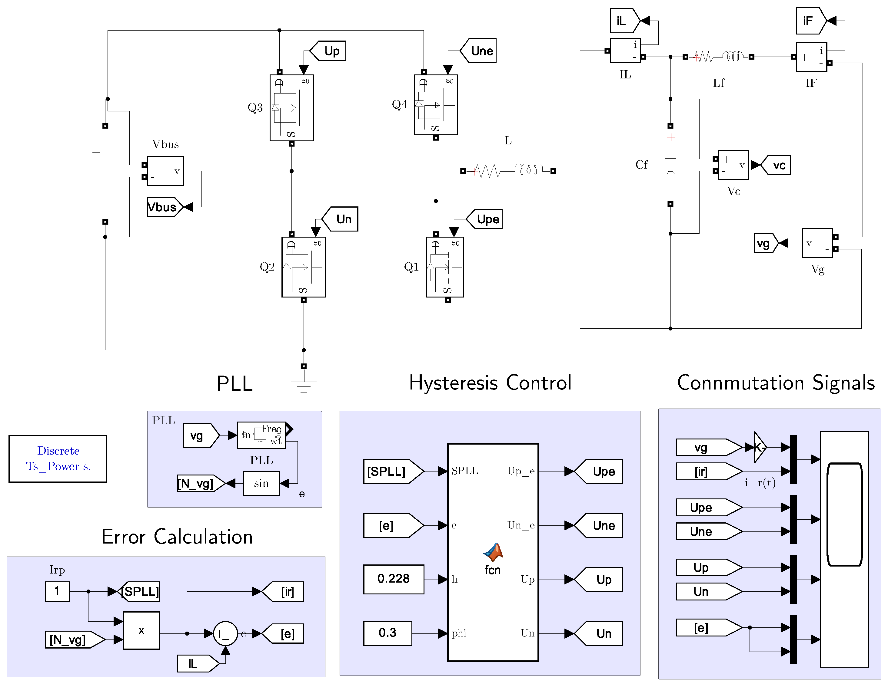
The numerical model of the inverter, implemented in Simulink–Matlab, is illustrated in Figure 8 and includes the parasitic resistances of both inductors. In addition, Table 1 details the values and specifications of the electronic components and semiconductors used.
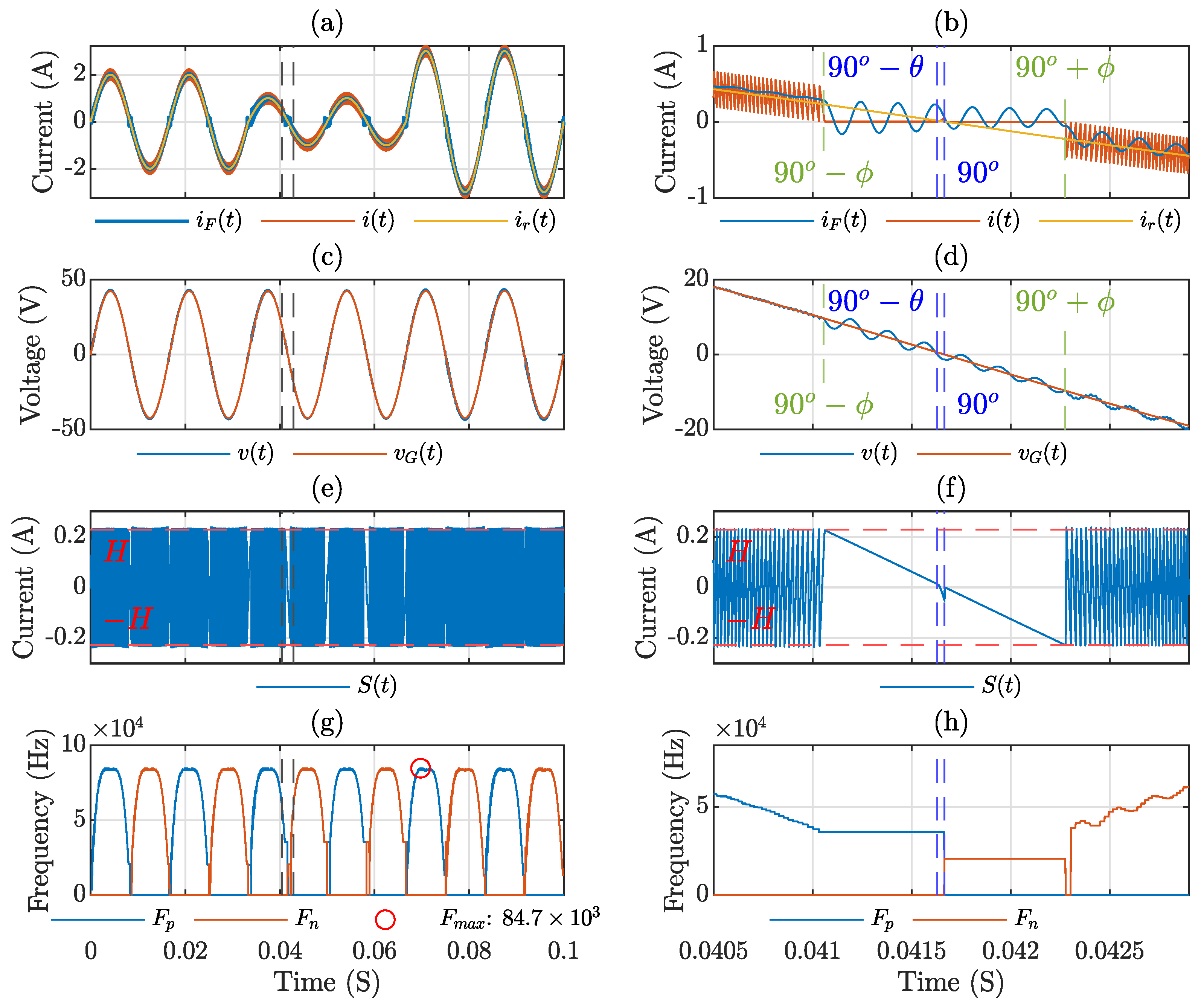
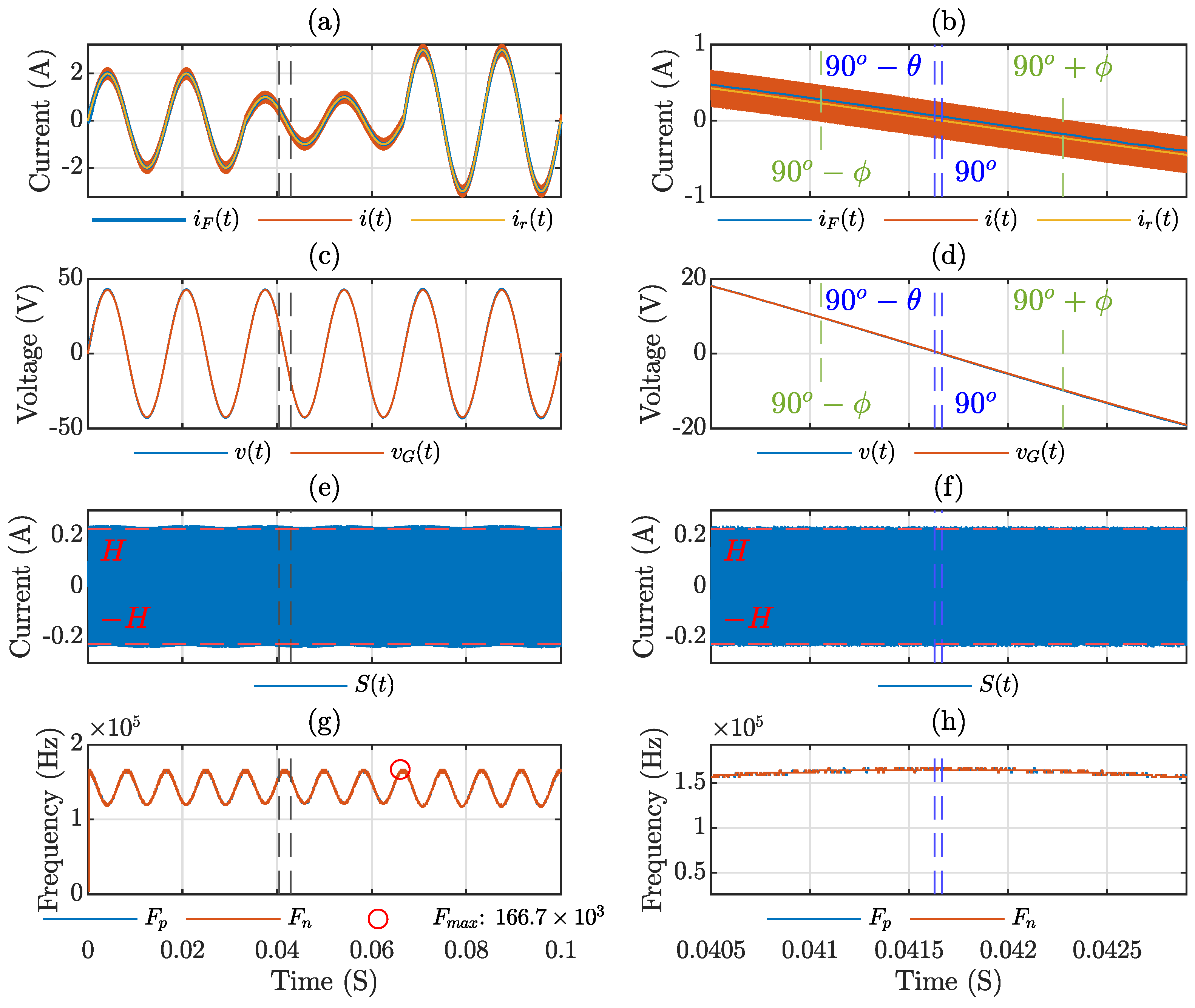
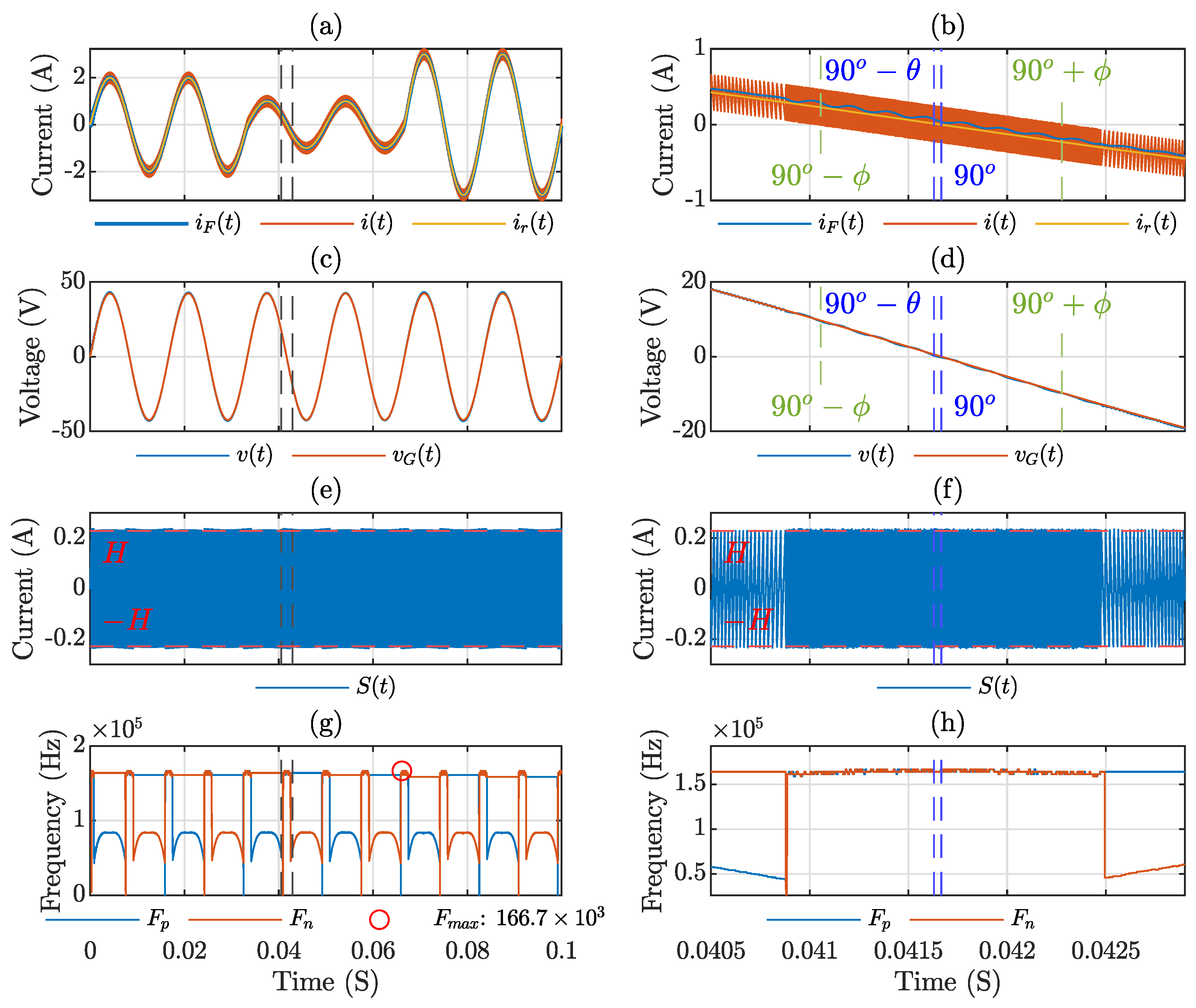
The simulation results for the operating modes FB-U, FB-B, and FB-H are introduced in Figure 9, Figure 10 and Figure 11, respectively. These figures show, from top to bottom, the currents ( i F ( t ) , i ( t ) , and i r ( t ) ); the voltages ( v c ( t ) and v G ( t ) ); the switching function ( S ( t ) ), and the switching frequency (F). In the simulations, I p = 2 A at the beginning, and then there are two-step changes to illustrate the controller performance for reference variations. The first step is from I p = 2 A to I p = 1 A at t = 2 / 60 s, and the second one is to I p = 3 A at t = 4 / 60 s. Additionally, the right side of those figures shows a zoom of the same variables around zero crossing at 40.5 m s. < t < 43.5 m s.
Figure 9a displays the current waveforms in the inverter during unipolar commutation; the black dotted lines demarcate the section for a zoomed view in the right-side figures. The two variations of I p described before and the ripples of i ( t ) and i F ( t ) produced by the SMC implemented with a hysteresis band of 0.2 A can be observed.
Figure 9b provides a closer examination of the phenomenon. It is evident that there is a loss of control near zero; the blue dotted lines delineate the stability limits as calculated by Equation (22) with θ = 0 . 8065 . However, here, the instability occurs before the angle θ , attributed to the width of the hysteresis band. When the lower band of the hysteresis crosses zero, the hysteresis control forces the current to switch to the negative side to commute the signal u ( t ) , but the operation mode for the positive semi-cycle cannot switch to the negative side, resulting in a zero current in i ( t ) during this phase. Control is only re-established when the upper hysteresis band crosses the zero axis, and the operation is shifted to the negative semi-cycle configuration. This pattern repeats at every zero-crossing point.
This discrepancy with the angle θ stems from the analytical procedure assuming H = 0 , whereas, in experimental implementation, H is assigned a value of 0.2 A. Figure 9c,d also clearly illustrate a distortion in the capacitor voltage due to the loss of control. Figure 9e,f show the switching function S ( t ) . Here, the sliding mode control cannot be achieved after the lower band touches zero; the red line indicates the hysteresis bands H. Figure 9g,h present the frequency variation during operation, noting that the maximum frequency in this scenario is 84.7 kHz, which reduces to the minimum at zero crossings.
Figure 10 shows the simulation results for the FB-B inverter. In Figure 10a–d, it is clear that there are no issues in the zero-crossing region, with no distortion observed in either the current or the voltage. The error, as shown in Figure 10e,f, stays consistently within the limits of the hysteresis band, as was demonstrated in Section 3.2. However, it should be noted that, in axes (g) and (h), there is a significant increase in the maximum frequency throughout the operation; the maximum frequency here is 166.7 Khz, almost double the unipolar commutation. This is because the rising and falling slopes of the inductor current depend on V B during FB-B commutation (i.e., u = 1 and u = 1 in (1)), while in FB-U mode, only one slope depends on V B ( u = 1 / u = 1 in (1)), and the other depends on i ( t ) and v ( t ) ( u = 0 in (1)).
Figure 11 presents the simulation results using the proposed hybrid commutation technique. In this simulation, Figure 11a shows that the stability of control during zero crossing is clearly maintained, allowing the current to smoothly adhere to the reference. The blue dotted lines indicate the angle at which stability is lost for unipolar commutation calculated as the angle θ . However, as was shown in Figure 9, the loss of control for this system is presented when the lower band crosses zero, which is shown in Figure 11b with the green lines corresponding to the angle ϕ , calculated from Equation (24).
For this implementation, the calculated ϕ m i n is 13 . 18 and the selected ϕ is 17 . 45 . Figure 11c,d show the voltage waveform, which now appears to be more sinusoidal and free of significant distortions. The error measurements, observed in Figure 11e, remain consistent within the limits of the hysteresis band. Furthermore, in Figure 11f, the transition from FB-U to FB-B commutation can be observed with a variation in switching frequency, which is confirmed in Figure 11g,h. Here, the frequency remains low for most of the operation, with a value of 87.4 kHz, although it increases to almost double ( 166.7 kHz) when the commutation switches to FB-B. However, the commutation losses in this region are minimal because of the low voltage.
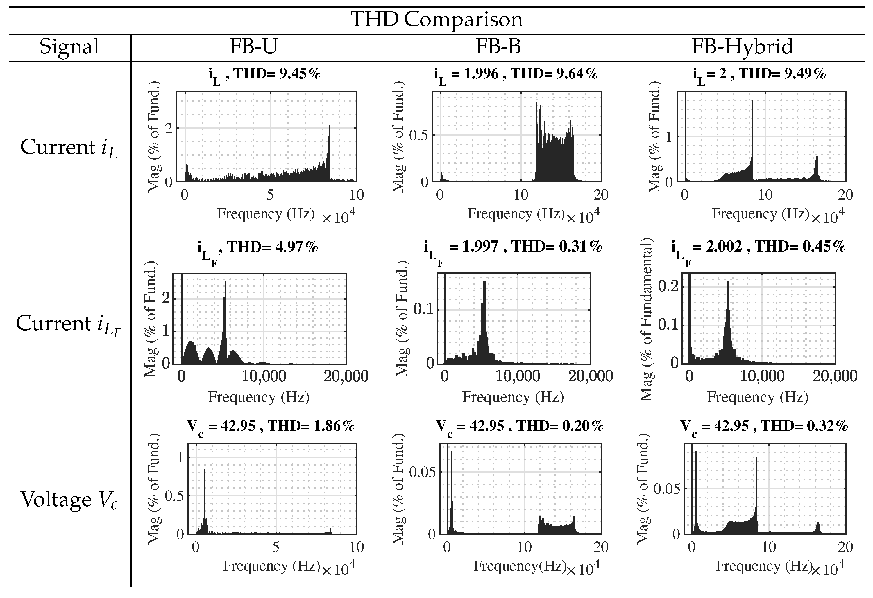
The THD analysis for all operation modes is summarized in Figure 12. The THD of both voltage and current was calculated using the THD block from Matlab/Simulink. Since the measurement of the THD varies depending on I p , the worst-case scenario was selected for analysis, occurring at 2 / 60 < t < 4 / 60 s. Among the modes of operation, the FB-U operation presents the worst-case scenario. The THDs of current and voltage in this mode meet the regulatory standards for grid-connected inverters, which require a THD of less than 5%. Conversely, the FB-B operation exhibits the best results, with a significantly reduced THD. The hybrid technique also demonstrates a low THD, close to the FB-B operation, thus capitalizing on the benefits of both FB-U and FB-B operations. The proposed method represents a balanced trade-off between the reduced switching losses of the FB-U operation and the enhanced stability of the FB-B inverter.
To compare the advantages of the hybrid method, a loss analysis was conducted. In [25], a detailed loss analysis for unipolar and bipolar commutation was performed. Here, the general equation for the loss of the inverter P loss is defined as
P loss = P SSall + P SWall + P DSSall + P RRall
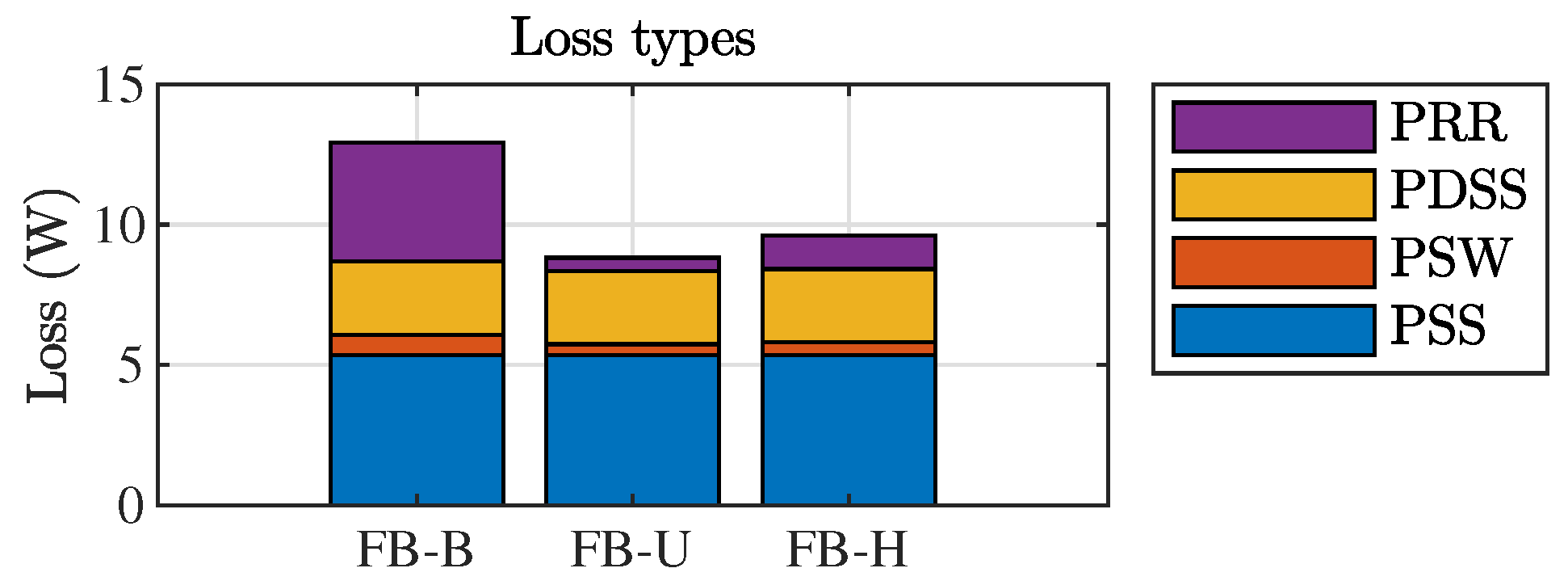
where P SS denotes the conduction loss of the MOSFET, P SW refers to the switching loss of the MOSFET, P DSS indicates the conduction loss of the body diode, and P RR signifies the reverse recovery loss. The suffix -all- represents the total losses for switches S p , S n , S p e , and S n e . Figure 13 presents the loss calculations for the FB inverter using the bipolar, unipolar, and proposed hybrid commutation techniques. The total loss for each configuration was 12.92 W, 8.81 W, and 9.61 W, respectively, with a voltage source of 84 V and an AC output current of 2 A peak . Here, the proposed method obtains the advantages of unipolar commutation, presenting low switching loss, close to the one obtained with FB-U.
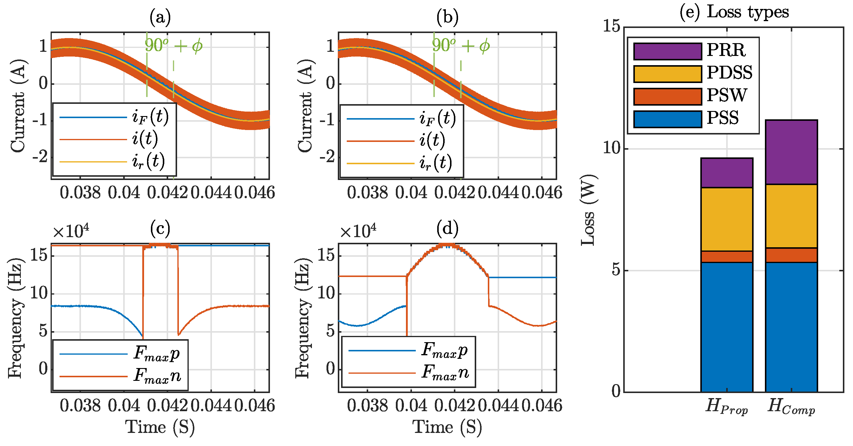
Among the hybrid methods proposed in the literature, most do not suggest an optimal point for switching from FB-U to FB-B. This is crucial for reducing the THD and switching losses. In [13], a hybrid method is proposed in which the rule to change the commutation method is v G = V B / 2 . A comparison of this method with the one proposed in this article is illustrated in Figure 14. Graphs (a) and (b) show the current in the Full-Bridge inverter for both methods. Our method reduces the angle for switching from unipolar (FB-U) to bipolar (FB-B) commutation, minimizing the high-frequency operation time, as shown in graphs (c) and (d). This reduction leads to lower switching losses, which is evident in the loss comparison in graph (e).
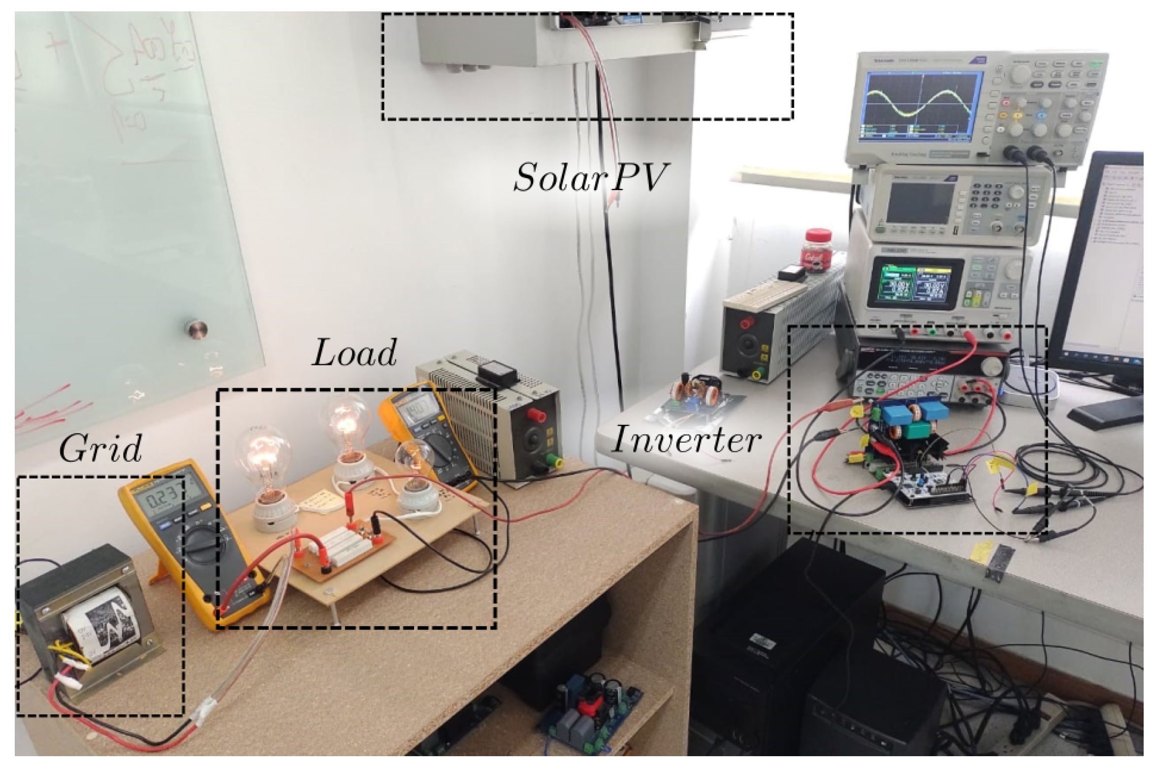
The experimental setup, illustrated in Figure 15, features a Full-Bridge inverter circuit, which was designed using Altium Designer 24.2.2 software and is controlled by an STM32G474RE microcontroller, manufactured by STMicroelectronics, and sourced from Geneva, Switzerland. This inverter is connected to 315 W solar photovoltaic panels mounted on the laboratory rooftop. For grid interfacing, a 120/30 VAC transformer is employed, facilitating the evaluation of circuit control within a low-voltage experimental network. A local load, comprising three 100 W incandescent light bulbs, is connected between the grid and the inverter output to visualize power flow. Initially, all energy is supplied by the grid; however, as the inverter starts to inject current, the energy drawn from the grid decreases until the inverter feeds the total energy to the load and back into the grid. The electrical specifications of this prototype are detailed in Table 1.
The implementation in the STM32G474RE microcontroller, as depicted in Figure 16, receives the input variables V G , i ( t ) , V B , and i r p and outputs the control signal u( u p , u n , u p e , u n e ). The Interrupt Service Routine (ISR) contains the initiation and control sequence for peripherals. The hysteresis bands are created by two digital-to-analog converters (DAC), and the inductor current is compared using two analog comparators. A high-resolution timer (HRTIM) functions as a flip-flop for the four control signals and is reconfigured online according to the control strategy.
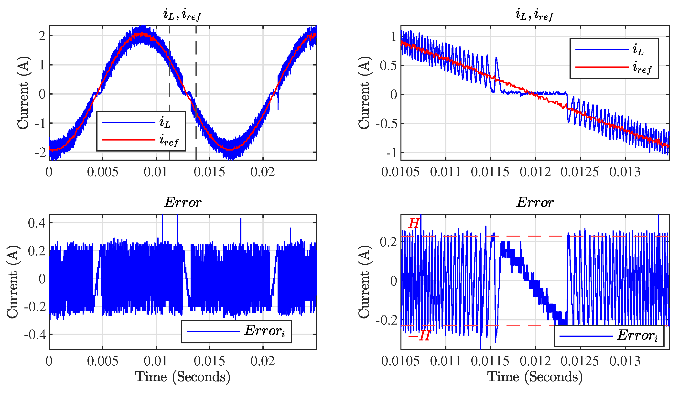
Figure 17 displays the current waveforms captured during the experiment using unipolar commutation. In the first row of the figure, the red line represents the reference current and the blue line depicts the inductor current. The graph on the right side provides a zoomed-in view of the zero-crossing distortion issue, where a noticeable deviation of the inductor current from the reference indicates a loss of control just when the lower hysteresis band reaches zero crossing. The second row illustrates how the error remains within the hysteresis band H = 0.228 A. A slow response in the zero-crossing region is clearly visible. Note that some glitches in the pictures are due to the noise of the measurement instruments.
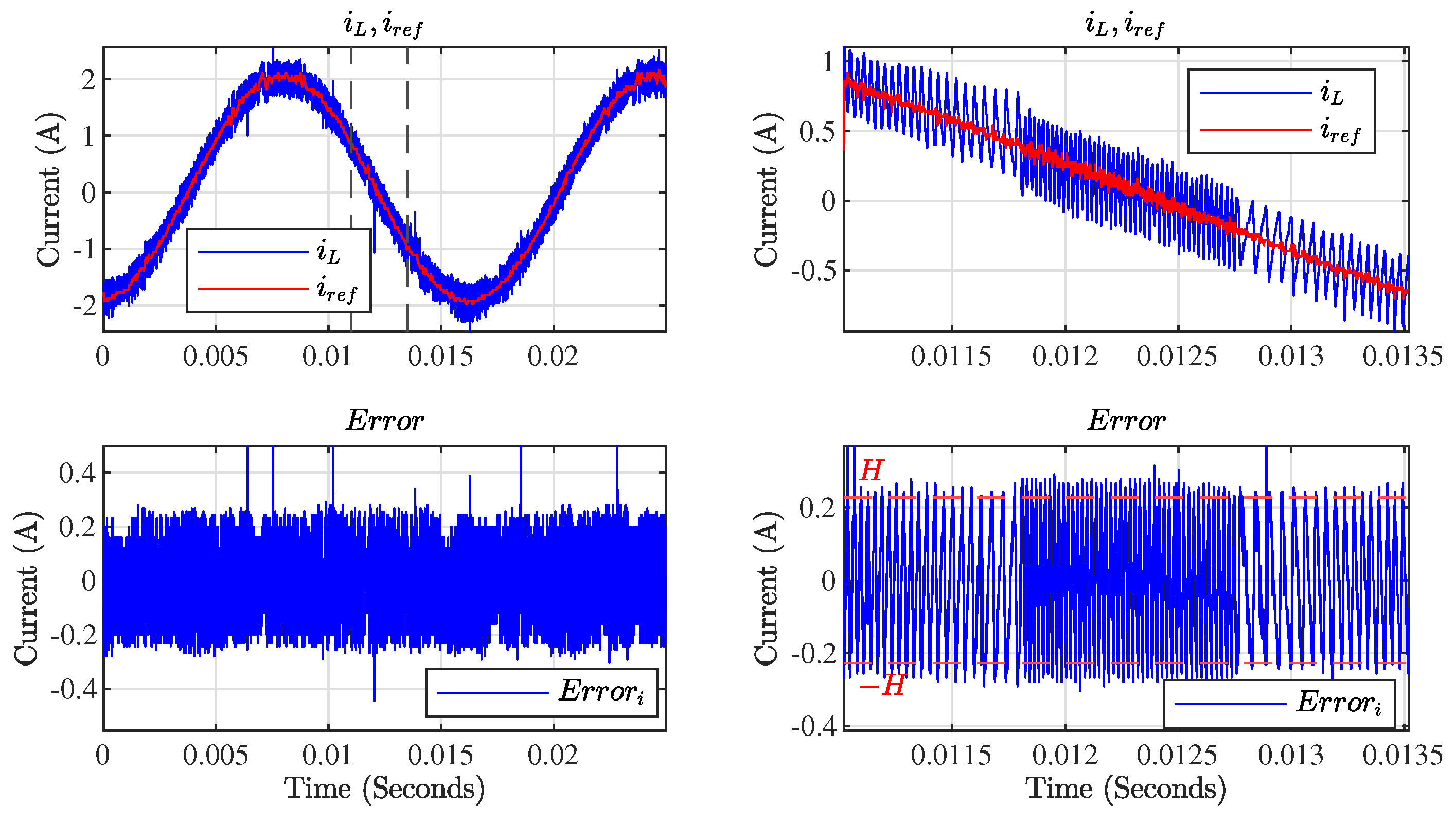
In Figure 18, the effectiveness of the proposed hybrid commutation technique is evident throughout the entire operation. Unlike earlier observations, the loss of control is not present here, and the inductor current closely aligns with the reference signal across all regions. It is clear in the first raw of the figure that the inductor current closely tracks the reference current, with a noticeable change in frequency near the zero-crossing region. Furthermore, the error graph highlights the frequency change during the zero-crossing point due to bipolar commutation, ensuring that the current remains within the hysteresis bands.
In the experimental analysis of the Full-Bridge inverter with unipolar commutation, a key focus was on evaluating the total harmonic distortion (THD) in various operational modes. Initially, as shown in Figure 19, the experiment assessed the THD of the current signal in the filter inductor when the inverter operated off-grid with a resistive load. The results in FB-U mode, illustrated in this figure, showed a THD of 5.39%. While this is within acceptable limits, it indicates potential areas for optimization. In contrast, the same figure demonstrates how the THD was notably reduced to 4.43% when the hybrid technique was used, highlighting the effectiveness of this method in reducing harmonic distortions in an off-grid scenario.
Moving to a grid-connected environment, Figure 20 captures the THD performance under more challenging conditions. When connected to an industrial grid, known for its relatively poor current quality, the inverter THD in FB-U operation jumped to 11.2%. This significant increase can be partially attributed to the inherent current quality issues of the grid. However, a noteworthy observation from the same figure is the substantial reduction in THD to 8.75% achieved by implementing the hybrid technique, emphasizing its capability to mitigate the THD in less-than-ideal grid conditions.
Lastly, the experiment examined the voltage THD in both FB-U and FB-hybrid modes while connected to the grid. As shown in Figure 21, the results indicated that both modes maintained low THD levels, but a slight improvement was observed with the hybrid method. This minor yet significant reduction underscores the efficacy of the hybrid technique in enhancing voltage waveform quality alongside its demonstrated impact on the current THD.
These experimental results validate the effectiveness of the proposed hybrid commutation technique in the Full-Bridge inverter. The technique provides improvements in the stability of the control of the inductor current, especially around zero-crossing regions, besides improving the THD.

5. Conclusions

This study presents a Full-Bridge inverter with a hybrid commutation technique for a sliding mode controller (SMC). The hybrid commutation strategically avoids the zero-crossing distortion limitations associated with unipolar commutation. The proposed commutation switches between unipolar and bipolar commutation modes in response to a loss of control. This enhances the robustness and overall efficiency of the system. We present the unipolar and bipolar operation modes of the inverter and validated transversality and reachability conditions for implementing a sliding mode controller, revealing a crucial range where control loss occurs during unipolar operation. We present an expression to compute critical angles where unipolar operation loses stability and provide guidelines on choosing parameters for the implementation of the controller.
The MATLAB/Simulink simulations verified the efficacy of the proposed hybrid technique against classical operations under perturbations in the reference. To showcase the advantages of the hybrid technique, we conducted a comparison of the THD, demonstrating that the hybrid method achieved a reduction of 4.52 percentage points in the current THD and 1.54 percentage points in the voltage THD with respect to the unipolar technique. The proposed method combines the low-loss benefits of unipolar commutation with the stability of bipolar commutation, effectively mitigating the drawbacks of each. The experimental results confirmed the theoretical and simulated findings: a reduction in percentage points of 0.96 for the local load (off-grid) and a reduction of 2.45 when the inverter was connected to the grid in an industrial environment, compared with unipolar commutation, confirming the practical viability of the proposed control technique.
The control law proposed in this paper is easy to implement and does not require the exact model of the entire system, making the controller suitable for various applications. The controller considers the nonlinear model of the inverter, enabling the tracking of the current reference for any operating condition. Unlike unipolar operation, the proposed control method consistently ensures accurate current tracking and supports the injection of reactive power into the grid. This capability is crucial for maintaining grid stability, especially with the increasing use of renewable energy sources. Furthermore, the digital implementation employs microcontrollers equipped with fast comparators capable of adapting to rapidly varying switching frequencies, thereby overcoming the challenges associated with widespread product deployment.

Author Contributions

Validation, M.A.B.-N.; Investigation, M.A.B.-N., J.D.B.-R. and G.O.; Writing—original draft, M.A.B.-N.; Supervision, G.O. All authors have read and agreed to the published version of the manuscript.

Funding

This work was supported by Universidad Nacional de Colombia, Rymel Ingeniería Eléctrica S.A.S., and Patrimonio Autónomo Fondo Nacional de Financiamiento para la Ciencia, la Tecnología y la Innovación Francisco José de Caldas—Ministerio de Ciencia, Tecnología e Innovación under the project “Validación tecnológica para la fabricación de reconectadores automáticos para redes inteligentes, del tipo seco con polos encapsulados utilizando compuestos poliméricos termoestables”, contract no. 099-2022.

Data Availability Statement

The original contributions presented in the study are included in the article, further inquiries can be directed to the corresponding author.

Conflicts of Interest

The authors declare no conflicts of interest.

References

  1. Kabalcı, E. Review on novel single-phase grid-connected solar inverters: Circuits and control methods. Sol. Energy 2020, 198, 247–274. [Google Scholar] [CrossRef]
  2. Hong, F.; Liu, J.; Ji, B.; Zhou, Y.; Wang, J.; Wang, C. Single Inductor Dual Buck Full-Bridge Inverter. IEEE Trans. Ind. Electron. 2015, 62, 4869–4877. [Google Scholar] [CrossRef]
  3. Khan, M.Y.A.; Liu, H.; Yang, Z.; Yuan, X. A comprehensive review on grid connected photovoltaic inverters, their modulation techniques, and control strategies. Energies 2020, 13, 4185. [Google Scholar] [CrossRef]
  4. Brinker, T.; Hoffmann, L.; Friebe, J. Comparison of Modulation Techniques for a Single-Phase Full-Bridge Photovoltaic Micro-Inverter Considering Reactive Power Capability. In Proceedings of the 2021 IEEE Energy Conversion Congress and Exposition (ECCE), Vancouver, BC, Canada, 10–14 October 2021; Institute of Electrical and Electronics Engineers Inc.: Piscataway, NJ, USA, 2021; pp. 841–846. [Google Scholar] [CrossRef]
  5. Tang, Y.; Zhang, C.; Guo, Y.; Sun, H.; Jiang, L. Optimization of Zero-Crossing Distortion for Unipolar BCM Grid-Tied Inverter. IEEE J. Emerg. Sel. Top. Power Electron. 2023, 11, 3680–3691. [Google Scholar] [CrossRef]
  6. Wu, T.F.; Kuo, C.L.; Sun, K.H.; Hsieh, H.C. Combined unipolar and bipolar PWM for current distortion improvement during power compensation. IEEE Trans. Power Electron. 2014, 29, 1702–1709. [Google Scholar] [CrossRef]
  7. Tang, Z.; Su, M.; Sun, Y.; Cheng, B.; Yang, Y.; Blaabjerg, F.; Wang, L. Hybrid UP-PWM Scheme for HERIC Inverter to Improve Power Quality and Efficiency. IEEE Trans. Power Electron. 2019, 34, 4292–4303. [Google Scholar] [CrossRef]
  8. Liu, B.; Su, M.; Yang, J.; Song, D.; He, D.; Song, S. Combined Reactive Power Injection Modulation and Grid Current Distortion Improvement Approach for H6 Transformer-Less Photovoltaic Inverter. IEEE Trans. Energy Convers. 2017, 32, 1456–1467. [Google Scholar] [CrossRef]
  9. Zeng, B.; Xu, H.B.; Chen, K.; Chen, J.G. Suppression of zero-crossing distortion for single-phase grid-connected photovoltaic inverters with unipolar modulation. Rev. Sci. Instrum. 2013, 84, 104705. [Google Scholar] [CrossRef] [PubMed]
  10. Wu, F.; Sun, B.; Zhao, K.; Sun, L. Analysis and Solution of Current Zero-Crossing Distortion with Unipolar Hysteresis Current Control in Grid-Connected Inverter. IEEE Trans. Ind. Electron. 2013, 60, 4450–4457. [Google Scholar] [CrossRef]
  11. Wu, F.; Li, X.; Duan, J. Improved Elimination Scheme of Current Zero-Crossing Distortion in Unipolar Hysteresis Current Controlled Grid-Connected Inverter. IEEE Trans. Ind. Inform. 2015, 11, 1111–1118. [Google Scholar] [CrossRef]
  12. Xie, R.; Zeng, Q.; Yang, F.; Lin, B.; Xu, O.; He, Y. Decoupled Unipolar Hysteresis Current Control for Single-Phase Grid-Tied Inverter Without Current Zero-Crossing Distortion. IEEE Access 2024, 12, 21453–21463. [Google Scholar] [CrossRef]
  13. Shimada, R.; Huang, C.; Mannen, T.; Isobe, T. Unipolar/Bipolar Mixed Modulation for Discontinuous Current Mode Single-Phase Grid-tied Inverter with Off-time Discrete Control. In Proceedings of the 2021 IEEE International Future Energy Electronics Conference (IFEEC), Taipei, Taiwan, 16–19 November 2021; IEEE: Piscataway, NJ, USA, 2021; pp. 1–6. [Google Scholar] [CrossRef]
  14. Chen, X.; Li, Q. Hybrid Modulation Method for Single Phase Full Bridge CRM Inverter to Improve Reactive Power Capability. In Proceedings of the 2024 IEEE Applied Power Electronics Conference and Exposition (APEC), Long Beach, CA, USA, 25–29 February 2024; IEEE: Piscataway, NJ, USA, 2024; pp. 2314–2319. [Google Scholar] [CrossRef]
  15. Lai, J.C.T.; Yeung, S.C.R.; Chung, H.S.H. Achieving Fast Dynamic Response and Output Filter Condition Monitoring in Hybrid PWM Inverters Using a Low-Computational State Trajectory Prediction Algorithm Incorporating With Reduced-Order Switching Surfaces. IEEE Trans. Power Electron. 2024, 39, 6941–6960. [Google Scholar] [CrossRef]
  16. Chen, J.; Wu, C.; Li, J.; Shao, Z.; Wang, J.; Wang, Y. A Low Distortion Collaborative Modulation for Zero-Crossing Distortion Pseudo DC Link Single-Stage Isolated Inverter. IEEE Trans. Power Electron. 2024, 39, 9132–9137. [Google Scholar] [CrossRef]
  17. Yao, R.; Wei, C.; Li, R. A Quasi-Trapezoidal Modulation Method with Zero-Voltage Switching for Single-Phase Inverters. In Proceedings of the 2023 IEEE 2nd International Power Electronics and Application Symposium (PEAS), Guangzhou, China, 10–13 November 2023; IEEE: Piscataway, NJ, USA, 2023; pp. 2088–2092. [Google Scholar] [CrossRef]
  18. Lin, L.; Zhang, J.; Shao, S. A Variable Switching Frequency Multimode Control Scheme for Single-Phase Grid-Tied Multilevel PV Microinverters. IEEE Trans. Power Electron. 2023, 38, 11543–11555. [Google Scholar] [CrossRef]
  19. Zhang, H.; Li, X.; Xiao, S.; Balog, R.S. Hybrid hysteresis current control and low-frequency current harmonics mitigation based on proportional resonant in dc/ac inverter. IET Power Electron. 2018, 11, 2093–2101. [Google Scholar] [CrossRef]
  20. Li, X.; Liu, Y.; Zhang, H. Hybrid-Modulation Hysteresis Scheme Based Decoupled Power Control of Grid-Connected Inverter. IEEE J. Emerg. Sel. Top. Power Electron. 2023, 11, 276–287. [Google Scholar] [CrossRef]
  21. Zheng, X.; Zhang, L.; Liu, X.; He, Y.; Shi, J.; Wang, C. Half-Cycle Control Method of the Bidirectional Three-Phase Dual-Buck Inverter without Zero-Crossing Distortion. IEEE J. Emerg. Sel. Top. Power Electron. 2021, 9, 2088–2097. [Google Scholar] [CrossRef]
  22. Sabi, K.; Costinett, D. Design and implementation of a bipolar-unipolar switched boundary current mode (BCM) Control GaN-Based single-phase inverter. In Proceedings of the 2019 IEEE Energy Conversion Congress and Exposition, ECCE 2019, Baltimore, MD, USA, 29 September–3 October 2019; pp. 6473–6480. [Google Scholar] [CrossRef]
  23. Zhang, Y.; Li, Y.; Tian, Y.; Zhao, H. Optimization of Boundary Current Mode Control Strategy for Reducing Zero-crossing Distortion in a H-bridge Inverter. In Proceedings of the 2021 IEEE 4th International Electrical and Energy Conference (CIEEC), Wuhan, China, 28–30 May 2021; Institute of Electrical and Electronics Engineers Inc.: Piscataway, NJ, USA, 2021. [Google Scholar] [CrossRef]
  24. Kumar, H.; Banerjee, S.; Mishra, S.K. A Method to Compensate for the Distortion of the Output Voltage of an H-Bridge Inverter Under Sinusoidal Unipolar PWM. In Proceedings of the 2022 IEEE Energy Conversion Congress and Exposition (ECCE), Detroit, MI, USA, 9–13 October 2022; IEEE: Piscataway, NJ, USA, 2022; pp. 1–7. [Google Scholar] [CrossRef]
  25. Haruna, J.; Masubuchi, N.; Iwase, S.; Funato, H. Loss analysis and efficiency enhancing method for a unipolar hysteresis-Controlled single-phase grid-connected inverter. IEEJ Trans. Electr. Electron. Eng. 2018, 13, 1182–1188. [Google Scholar] [CrossRef]
  26. Bolaños-Navarrete, M.A.; Bastidas-Rodríguez, J.D.; Osorio, G.A. Hysteresis control for a grid connected dual-buck inverter. Rev. UIS Ing. 2020, 20, 1–10. [Google Scholar] [CrossRef]
  27. Bolaños, M.A.; Osorio, G.; Bastidas-Rodriguez, J.D.; Revelo-Fuelagan, E. Computational Model of a Two-stage Microinverter With Flyback Active Clamp and Dual Buck. In Proceedings of the 2019 IEEE 4th Colombian Conference on Automatic Control (CCAC), Medellin, Colombia, 15–18 October 2019. [Google Scholar]
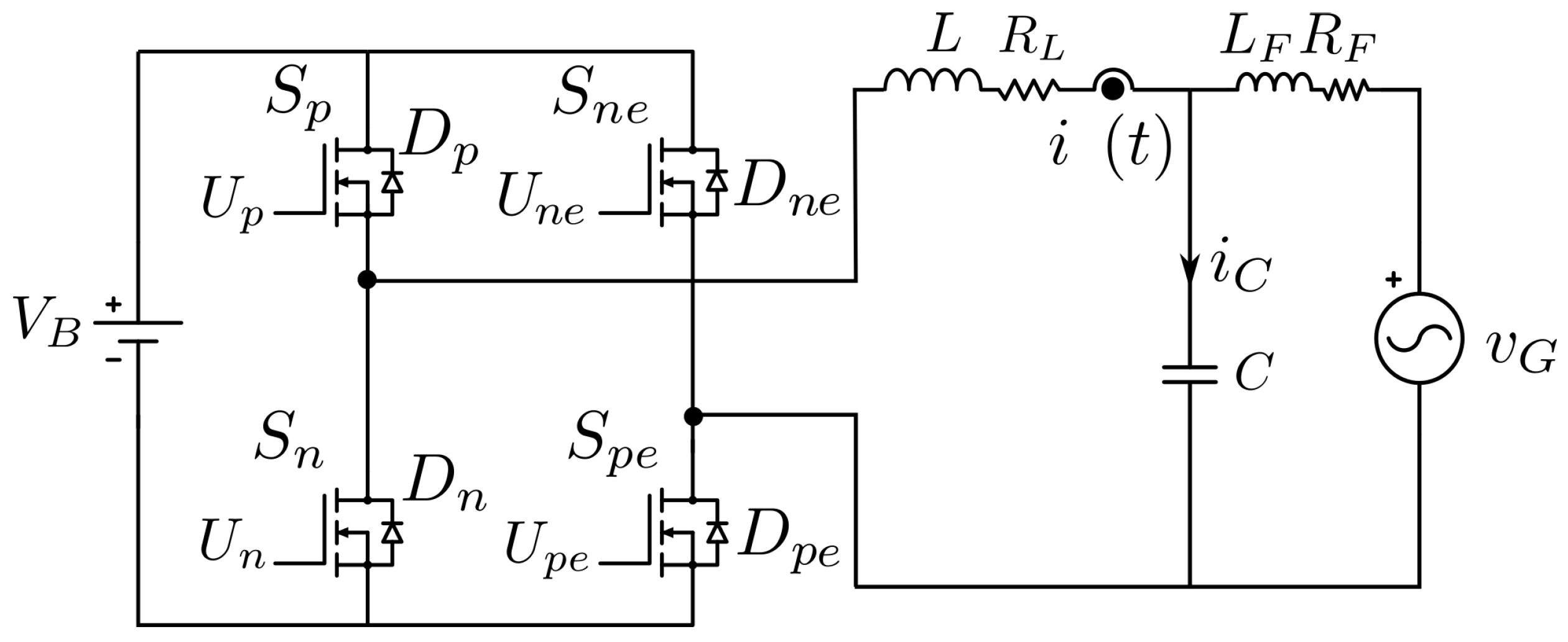
Figure 1. Full-Bridge inverter for on-grid applications.
Energies 17 03671 g001
Figure 2. (a) Inverter output voltage, (b) unipolar modulation, (c) bipolar modulation, and (d) hybrid modulation.
Energies 17 03671 g002
Figure 3. Unipolar commutation in the positive half cycle of v G .
Energies 17 03671 g003
Figure 4. Unipolar commutation in the negative half cycle of v G .
Energies 17 03671 g004
Figure 5. Bipolar commutation for all the ranges of v G .
Energies 17 03671 g005
Figure 6. Control strategy blocks.
Energies 17 03671 g006
Figure 7. Critical limits for the sliding mode controller in unipolar commutation.
Energies 17 03671 g007
Figure 8. Implementation of the inverter in Simulink.
Energies 17 03671 g008
Figure 9. FB-U inverter simulation with step variations in I p ( I p = 2 for 0 ms < t < 2/60 ms, I p = 1 for 2/60 ms < t < 4/60 ms, and I p = 3 for 4/60 ms < t < 6/60 ms). From top to bottom, currents ( i F ( t ) , i ( t ) , and i r ( t ) ); voltages ( v ( t ) and v G ( t ) ); switching function ( S ( t ) ); and switching frequency (F). The black dashed lines in (a,c,e,g) mark the areas for a zoomed view in the figures on the right. The blue dashed lines in (b,d,f,h) show the stability boundaries for θ as determined by Equation (22). The green lines in (b,d) indicate the stability boundaries resulting from the use of hysteresis bands, corresponding to the angle ϕ , derived from Equation (24), i.e., when the lower band crosses zero.
Energies 17 03671 g009
Figure 10. FB-B inverter simulation with step variations in I p . From top to bottom, currents ( i F ( t ) , i ( t ) , and i r ( t ) ); voltages ( v ( t ) and v G ( t ) ); switching function ( S ( t ) ); and switching frequency (F). The black dashed lines in (a,c,e,g) indicate zoom areas on the right. The blue dashed lines in (b,d,f,h) show the stability boundaries for θ from Equation (22). The green lines in (b,d) mark stability boundaries from hysteresis bands for angle ϕ per Equation (24).
Energies 17 03671 g010
Figure 11. FB-H inverter simulation with step variations in I p ( I p = 2 for 0 ms < t < 2/60 ms, I p = 1 for 2/60 ms < t < 4/60 ms, and I p = 3 for 4/60 ms < t < 6/60 ms). From top to bottom, the currents ( i F ( t ) , i ( t ) and i r ( t ) ), the voltages ( v ( t ) and v G ( t ) ), the switching function ( S ( t ) ), and the switching frequency (F). The black dashed lines in (a,c,e,g) mark the areas for a zoomed view in the figures on the right. The blue dashed lines in (b,d,f,h) show the stability boundaries for θ as determined by Equation (22). The green lines in (b,d) indicate the stability boundaries resulting from the implementation of hysteresis bands, corresponding to the angle ϕ , derived from Equation (24), i.e., when the lower band crosses zero.
Energies 17 03671 g011
Figure 12. THD comparison in currents ( i L , i L f ) and voltage ( V c ) for the three types of commutations (FB-U, FB-B, and FB-hybrid) for the Full-Bridge inverter, showing the total harmonic distortion (THD) percentages for each configuration.
Energies 17 03671 g012
Figure 13. Loss calculation for the three types of commutation (FB-B, FB-U, and FB-H) for the Full-Bridge inverter, showing the contributions of reverse recovery loss (PRR), conduction loss of the body diode (PDSS), switching loss of the MOSFET (PSW), and conduction loss of the MOSFET (PSS).
Energies 17 03671 g013
Figure 14. Comparison of the proposed method with the one in [13]. Graphs (a,b) show current waveforms, and graphs (c,d) show switching frequencies. The proposed hybrid method reduces high-frequency operation time, leading to lower switching losses, as shown in graph (e). The green lines in (a,b) indicate the boundaries given by ϕ where the proposed technique marks the transition from unipolar to bipolar commutation and vice versa.
Energies 17 03671 g014
Figure 15. Experimental setup for the Full-Bridge inverter.
Energies 17 03671 g015
Figure 16. Implementation in a STM32G474RE microcontroller.
Energies 17 03671 g016
Figure 17. Currents i L , i r e f and error signal e in the experimental FB-U inverter.
Energies 17 03671 g017
Figure 18. Experimental signals of current i L , i r e f and error e, with the FB-H method.
Energies 17 03671 g018
Figure 19. Comparison of the current i F with (a) FB-U and (b) FB-H operations with a resistive load.
Energies 17 03671 g019
Figure 20. Comparison of the current i F with (a) FB-U and (b) FB-H operations connected to the grid.
Energies 17 03671 g020
Figure 21. Comparison of the voltage i F with (a) FB-U and (b) FB-H operations connected to the grid.
Energies 17 03671 g021
Table 1. Inverter component values and control implementation parameters.
ComponentValueUnits
ComponentL540  μ H
R L 0.320 Ω
L F 270  μ H
R F 0.160 Ω
C3.3  μ f
v G 21.21 V r m s
V b u s 88V
Control Parameters ϕ m i n 13.18
θ0.8065
i r p 2, 1, 3A
H228 mA
F m i n 1 kHz
Disclaimer/Publisher’s Note: The statements, opinions and data contained in all publications are solely those of the individual author(s) and contributor(s) and not of MDPI and/or the editor(s). MDPI and/or the editor(s) disclaim responsibility for any injury to people or property resulting from any ideas, methods, instructions or products referred to in the content.