Abstract
Over the past two decades, double-layered microchannel heat sinks (DL-MCHs) have become increasingly popular as they provide effective performance for electronic cooling, particularly in the counterflow configuration. The cross-flow configuration, which requires much simpler headers, has seldom been considered in the scientific literature, probably due to the possible formation of a hotspot near the outlet port. The aim of this study is to show that cross-flow DL-MCHs can provide performance levels that are comparable to those attained by counterflow DL-MCHs by exploiting the nonuniform flow distribution produced by properly designed headers. Numerical simulations are performed using in-house finite element procedures to solve the parabolized Navier–Stokes equations in the microchannels and the energy equation in the entire computational domain. The analysis is carried out both for ideal linear microchannel velocity distributions and for the realistic velocity distributions induced by headers with or without baffles, as proposed by the authors in previous papers. The optimal degree of velocity nonuniformity in the microchannels yielding the best thermal performance was found to depend on the flow rate. For instance, in the case of optimal linear variations of the microchannel velocity distribution, the thermal resistance was reduced by 11.8%, 7.1%, and 4.4% compared to the case with uniform inlet velocities, and it was only 3.4%, 1.8%, and 0.3% higher than that of the counterflow configuration for average microchannel velocities equal to 0.5, 1, and 2 m/s, respectively. The main conclusion is that the cross-flow configuration, with its simple headers and piping, can achieve thermal resistance and temperature uniformity on the heated surface that are very similar to that of the counter-flow configuration through proper header design that ensures a suitable microchannel velocity distribution.
1. Introduction
In the early 1980s, a well-known paper by Tuckerman and Pease first proposed the use of liquid-cooled microchannel heat sinks (MCHSs) for the thermal control of electronic devices [1]. In the beginning, these MCHSs consisted of a single layer of microchannels parallel to each other, and they were etched or machined into a substrate (often silicon or metal) in direct contact with the electronic component to be cooled (usually a microchip). An inlet header distributes the coolant that flows through all microchannels in the same direction and is collected by an outlet header. This configuration has the merit of simplicity but results in an uneven temperature distribution in the direction of flow since, necessarily, the part of the heated surface near the outlet of the microchannels is hotter than that near the inlet. In any event, this type of MCHS was improved in subsequent years and optimized by studying the effects that characteristic geometric parameters of microchannels (e.g., the size and shape of the cross-section, the number of microchannels, the geometry of side surfaces, and the presence of ribs or pin fins) could have on thermal performance. There are hundreds of published articles on the subject, and they are mentioned in numerous review papers on heat transfer enhancement in MCHSs, some of which are also very recent [2,3,4,5,6,7,8].
About twenty-five years ago, Vafai and Zhu [9] first proposed a double-layered MCHS (DL-MCHS), which features two sets of vertically stacked microchannel layers separated by a thin solid wall. The coolant flows through both layers according to either a parallel flow or a counterflow configuration. The double-layered structure significantly increases the heat transfer surface area, thus enabling a reduction in thermal resistance, an increase in cooling efficiency, and an improvement in temperature distribution. The DL-MCHS, especially in the counterflow configuration, has been shown to provide better temperature uniformity and greater cooling capacity compared to single-layered MCHSs [10], particularly for high flow rates [11], but it does require two separate inlets and two separate outlets on opposite sides. Over the past two decades, the use of double-layered MCHSs (DL-MCHSs) has become increasingly popular; also, with reference to this type of heat sink, dozens of papers have been published describing both experimental and numerical studies. For example, based on the latter type of analysis, Wu et al. [12] not only confirmed that, with the counterflow arrangement, it is possible to achieve a greater uniformity of the heated surface temperature than is possible with a single-layered microchannel heat sink, but they also pointed out that a better performance is achieved with a higher aspect ratio, a smaller width ratio, and a lower velocity in the upper layer microchannels than in those of the lower layer. Hung et al. [13] further investigated the influence on the heat transfer of parameters, such as the channel number, channel width ratio, channel aspect ratio, substrate material, and thickness. Kulkarni et al. [14] studied the effect of seven shapes of microchannel cross-sections (i.e., boot, diamond, hexagonal, pentagonal, rectangular, rectangular wedge, and triangular) in parallel and counterflow arrangements of double-layered MCHSs. Lin et al. [15] used the conjugate gradient method to optimize the performance of a DL-MCHS as a function of six parameters (namely channel number, bottom channel height, vertical rib width, thickness of the two horizontal ribs, and coolant velocity) for fixed values of pumping power, coolant volume flow rate, and pressure drop. The flow rate in the two layers may be different, and the ratio of that in the upper layer to that in the lower layer represents a design variable, as well as the relative height of the microchannels. Lin et al. [15] and Leng et al. [16] found that, in many cases, a higher coolant velocity in the bottom microchannels and a lower bottom channel height are desirable. Shen et al. [17] proposed a variant of the DL-MCHS, with a wavy configuration, with a swap of the upper and lower layers. Sharma et al. [18] investigated the effects of using trapezoidal cross-sectional microchannels in a DL-MCHS with counter- and parallel-flow configurations, whereas Wong and Ang [19] studied the effects from the use of vertically tapered and converging microchannels. Meanwhile, Borah et al. [20] recently analyzed the thermohydraulic performance of wavy, tapered channels in a DL-MCHS. As the last example, one can mention the work of Zhai et al. [21], who numerically studied the characteristics of flow and heat transfer in double-layered microchannels with cavities and ribs.
In order to optimize the use of computational resources in all the above cases, numerical studies were carried out using computational domains that are representative of a very small portion of the considered DL-MCHS, and they were obtained by exploiting existing symmetries. However, this approach, which corresponds to assuming a uniform distribution of the average velocity in the microchannels, does not allow for taking into account the effects of headers on the actual velocity distribution in the microchannels. In actuality, in many cases, this may be far from uniform, i.e., it is affected by significant flow maldistribution, which, in general, has a negative effect on the thermal performance of heat exchangers. Therefore, every effort is made to reduce it as much as possible [22,23,24,25]. Meanwhile, not taking it into account in the numerical studies evidently detracts from the reliability of the computed results. In addition, because of the reduced domains used in the numerical simulations, the analysis of the effects due to the parasitic heat transfer that necessarily takes place outside the counterflow DL-MCHSs core where inlet and outlet headers are adjacent to each other was also not investigated in depth. In fact, in that part of the devices, the hot fluid flowing in the outlet headers preheats the cold fluid in the inlet headers, which are separated from the former only by a thin wall. In this regard, it is important to recall that the counterflow configuration requires two inlet and two outlet headers on opposite sides of the DL-MCHS [11]. Moreover, these headers, besides being partially adjacent to each other, can also be quite complex, as was the case of the DL-MCHS experimentally studied by Wei et al. [26]. As it is easy to guess, both of these effects (flow maldistribution and parasitic heat transfer) result in a thermal performance degradation compared to the theoretical ones reported in most articles concerning counterflow DL-MCHSs. Nevertheless, the numerical studies found in the literature, in which the effect of manifolds was also considered, are very few and mainly concern the case of single-layered MCHSs [27,28,29,30,31,32]. Other studies concern manifold MCHSs [33]; these, however, have headers of a different type than those considered in this work. Very little can be found, instead, for the case of DL-MCHSs. In any event, Elqady et al. [34] concluded that neglecting the effect of headers does not significantly reduce the accuracy in the case of parallel flow DL-MCHSs, but it has a considerable impact on the reliability of simulation results in the case of a counterflow configuration.
As already mentioned, a counterflow DL-MCHS requires the use of geometrically complex headers comprising two inlet and two outlet ports [11]. In contrast, the type of piping required to have a cross-flow arrangement in DL-MCHS can be quite simple because (as can be seen in Figure 1, where it is assumed that the surface in contact with the electronic component to be cooled is the bottom surface) it is sufficient to have headers with only one inlet and one outlet port. On the other hand, according to a review of the scientific literature, a DL-MCHS based on the cross-flow configuration (XF-DL-MCHS) has rarely been taken into consideration. For instance, only Ansari et al. [35] evaluated the performances of various XF-DL-MCHS configurations, and Ansari et al. [36], in addition to considering parallel and counterflow designs for DL-MCHSs, have also investigated the thermal behavior of an XF-DL-MCHS for the mitigation of randomly distributed hotspots under nonuniform heating conditions of the base surface. One of the reasons why the cross-flow configuration has been neglected is probably due to the fact that when the streams in the two microchannel layers are in cross-flow, a hotspot necessarily forms on the heated surface near the outlet port because, in that area, the cooling fluid arrives already heated in the microchannels of both layers. The formation of a hotspot is evidently exactly what one would want to avoid so as not to jeopardize the integrity of the electronic components that the cooling system is supposed to protect. Therefore, this type of flow configuration seems to be poorly suited. Nevertheless, it is also conceivable that, with an appropriate header design, it is possible to achieve a nonuniform velocity distribution in the microchannels of the two layers that would allow hotspot mitigation. This aspect is further explored in this paper.

Figure 1.
A cross-flow, double-layered microchannel heat sink: the overall geometry including headers (arrows indicate flow direction in microchannel layers and dotted line corresponds to bottom layer) (left); and detail showing the microchannel positions in the two layers (right).
These authors had previously demonstrated that hotspot mitigation may be accomplished by taking advantage of the flow maldistribution that headers typically induce, which can lead to an increase in velocity in the microchannels that are closer to the outlet port and more distant from the inlet port [37]. In the current study, a numerical analysis was conducted to determine what degree of velocity nonuniformity is required to provide optimal thermal control of the heated surface of an XF-DL-MCHS in the ideal case of a velocity that varies linearly in the microchannels of both layers, with lower values near the inlet port and higher values near the outlet port. The thermal performance of the same XF-DL-MCHS has also been evaluated in the case where the microchannel velocity nonuniformity is produced by the manifolds analyzed by Savino et al. [38]. The aim was to assess the performance of XF-DL-MCHSs with header geometries that, even with the inclusion of appropriate baffles, allow an enhancement of the flow maldistribution that is naturally provided by actual headers. All this with the purpose of demonstrating that XF-DL-MCHS can represent a viable solution for the thermal control of microelectronic devices.
The description of the problem considered and the adopted numerical procedure for the solution are reported in Section 2. The purpose of this work is to demonstrate that, with XF-DL-MCHSs and appropriate velocity distributions in the microchannels, it is possible to obtain an adequate temperature control of the microchips. First, the effects on the thermal performance attainable under an ideal condition corresponding to a linear variation of the velocity in the microchannels are analyzed in Section 3. Then, those achievable in practice with realistic headers, with or without the aid of baffles such as those already studied from a hydrodynamic point of view in a previous work [38], are described in Section 4. Finally, a comparison of the results obtainable with cross-flow DL-MCHSs and those provided by counterflow DL-MCHSs of similar characteristics is presented in Section 5.
2. Statement of the Problem and Numerical Procedure
To prove the applicability of XF-DL-MCHSs to the thermal control of microchips provided there is an appropriate nonuniform microchannel velocity distribution, the analysis was conducted with reference to a geometry previously considered in [39], having a footprint and microchannel dimensions that can be considered typical for devices of this type. With reference to the same heat sink geometry, an analysis of the flow in the manifolds was then conducted [38]. The corresponding microchannel velocity distributions were used for some of the thermal analyses carried out in this work. In any event, it must be remembered that, here, the authors are merely trying to prove a concept and are not attempting to design or optimize an actual device. Consequently, the considered XF-DL-MCHS has a square footprint with side dimensions of . In each layer, it has identical microchannels, with a height and a width equal to the thickness of all solid walls. The MCHS is made of silicon, with thermal conductivity equal to , and the cooling fluid is water at the inlet temperature , with density, dynamic viscosity, thermal conductivity, and specific heat equal to , , , and , respectively. A uniform specific heat flux was applied to the heated surface, while all other surfaces are assumed to be adiabatic. This assumption was adopted in all the studies that were conducted on reduced portions of the domain corresponding to one or two microchannels [15,16]. It was also retained here for the purpose of highlighting the effect on thermal performance being solely due to the microchannel velocity distribution and to facilitate comparisons. Three values of the total volumetric flow rate of , , and were considered, corresponding to the average microchannel velocities of , , and , respectively, where is the velocity in the j-th microchannel. With all average velocities considered in this work, which were assumed equal in both layers, the Reynolds number remained below 1000 in all microchannels, even in the case of a nonuniform distribution, which implies laminar flow in all cases.
The numerical study of the thermal performance of the MCHS required a solution of the coupled convection–conduction problems to obtain the temperature distributions in the solid/fluid domain corresponding to the core of the device. For this purpose, an in-house finite element procedure—valid in the case of laminar fluid flows of constant property fluids, was previously developed by the authors, and described in detail in other papers [39,40,41]—was used. Therefore, only the main steps required for the calculation of the flow fields in the microchannels and the thermal field in the whole MCHSs are summarized here.
- The velocity field within the microchannels was obtained from the solution of the parabolized Navier–Stokes equations in the direction of the flow in a reference microchannel having the same cross-section as those in the MCHS.
- The velocity field thus obtained was then mapped onto the portions corresponding to the microchannels in the discretized three-dimensional domain where the energy equation will be solved. This can be performed by taking advantage of the fact that, under the adopted assumptions, the velocity distribution over the cross-section of the microchannels is unique for any given dimensionless axial distance , where x is the axial coordinate, is the hydraulic diameter, and is the Reynolds number. This way, it is possible to accurately account for the entrance effects in all the microchannels, even if the velocities are not equal.
- Since the mesh density used for solving the Navier–Stokes equations in the reference microchannel was different from that used for discretizing the domain corresponding to the MCHS, the mapped velocity field no longer satisfied the discrete form of the continuity equation due to the necessary interpolations. To recover local and global mass conservation, the necessary velocity corrections were calculated by solving a Poisson equation for each microchannel with a procedure similar to that used in the framework of methods for solving Navier–Stokes equations based on projection algorithms.
- Finally, the elliptic form of the steady-state energy equation was solved over the entire solid/fluid domain to determine the temperature field.
It must be pointed out that, to allow the use of elongated elements in the flow direction in order to reduce the total number of nodes of the discretization without compromising the accuracy of the results, the solid/fluid subdomains corresponding to the two microchannel layers were discretized separately using nonconforming grids at the common interface located in the mid-plane of the solid layer separating the upper and lower microchannels. For the coupling of the two thermal fields at the common boundary, a method developed by the authors and already described in previous papers, was used [40,41]. It is based on the weak enforcement of flux and temperature continuity at the interface by imposing
where is an empirical weighing factor; and are suitable reference heat flux and reference temperature difference values, respectively; while and denote the adjacent solid boundaries of the two layers of microchannels.
Since no experimental data on cross-flow MCHSs appeared to be available in the literature, the validation of the procedure was conducted by comparison with the data on a cross-flow micro heat exchanger that was experimentally analyzed by Brandner et al. [42]. This consisted of 50 square stainless-steel layers (25 per fluid pass) with 34 microchannels each and dimensions of , including a border along each side. Therefore, the part useful for heat transfer turned out to be . As reported in previous work [40,41], the agreement between experimental and numerical results, which were compared for five values of the mass flow rate of hot and cold fluids, was quite satisfactory and confirmed the validity of the adopted procedure.
A schematic representation of the computational domain, which corresponds to the XF-DL-MCHS that was considered here and was used for the solution of the thermal energy equation, is shown in Figure 2 (left side), and it corresponds to the core part of the MCHS that provides the cooling for the heated surface. The spatial discretization was performed using 22,100,000 eight-node hexahedral elements, with the number of nonuniform subdivisions in each microchannel of each of the two layers equal to 250 in the flow direction, 16 in the transverse direction, and 24 in the vertical direction. A detail of the mesh is also shown in Figure 2 (right side). Conjugate heat transfer problems similar to the one considered in this paper have already been solved by the authors in previous research [39,40,41]. A grid resolution comparable to that used here has been shown to be more than adequate to ensure results that are mesh-independent. In particular, the same mesh has also been used satisfactorily in a previous study to discretize the same domain [39]. The mesh used for solving the parabolized form of the Navier–Stokes equations in the reference microchannel was characterized by a significantly higher spatial resolution than that used for the entire MCHS to ensure the accuracy of the results.

Figure 2.
Schematic representation of the core of the cross-flow, double-layered microchannel heat sink, also showing the inlet port position and qualitative microchannel velocity distribution (left) and the detail of the finite element mesh (right).
3. Effects of Linear Velocity Variation
In this work, the first step toward identifying the type of velocity nonuniformity in the microchannels that can enable improved thermal performance was to study the effect on the temperature distribution of the heated surface that can occur under an ideal condition in which the velocity in the microchannels of both layers varies linearly, with lower values near the inlet port and higher values at the opposite ends. This type of velocity distribution is qualitatively illustrated in Figure 2 (left side), where the core of a DL-MCHS is depicted and the microchannel inlets of both layers are marked. The velocity nonuniformity is characterized by the flow maldistribution parameter (assumed to be the same for both layers), and it is defined as the normalized difference between the velocity in the last () and in the first () of the 50 microchannels in each layer [38]:
The lower the microchannel identification number, the closer it is to the inlet port and the lower the fluid velocity, which varies linearly with the microchannel position. This parameter was adopted to give an intuitive indication of how far the considered linear velocity distribution was from a uniform one. Its value can thus be considered a measure of the flow maldistribution.
Figure 3, Figure 4 and Figure 5 show the temperature distributions on the heated surface for different values of the maldistribution and for the three values of the average velocity in the microchannels considered in this study. It is apparent that, with all velocities, the worst conditions occurred for , which corresponds to the uniform microchannel velocity case and results in the maximum temperature value at the corner of the surface near the outlet port.It can also be seen that, as the nonuniformity in the velocity of the microchannels increased, the hotspot was mitigated with values of for , for , and for , for which the value of the maximum temperature on the heated surface was the lowest. For higher values of , however, the temperature control on the lower surface was reduced due to the formation of a hotspot at a location closer to the entrance of the microchannels of the upper layer. It was also apparent that, as the average velocity increased, there was a reduction in the value of that allows for the best performance.

Figure 3.
Linear variations of the microchannel velocity: heated surface temperature distributions for different values of and where .

Figure 4.
Linear variation of the microchannel velocity: heated surface temperature distributions for different values of and where .

Figure 5.
Linear variation of the microchannel velocity: heated surface temperature distributions for different values of and where .
Further quantitative results concerned the total thermal resistance [11,13,39]
and the maximum temperature difference over the heated surface, which gives a measure of temperature uniformity over the surface,
where and are the maximum and the minimum temperatures on the base surface, respectively. The values of the parameters calculated with Equations (3) and (4) are reported in Table 1, Table 2 and Table 3, and they are consistent with the conclusions drawn in Section 2 and Section 3 for the three average velocities considered in this study and for a greater number of values of parameter than those used in Figure 3, Figure 4 and Figure 5. Also shown in the same tables are the maximum pressure drops in the MCHS, which are significantly dependent on the degree of velocity nonuniformity in the microchannels. In addition, to facilitate the interpretation of the results, the rightmost three columns of the tables show the percentage variations , , and of the parameters , , and from the value pertaining to the case of a uniform velocity distribution in the microchannels (), which was taken as the reference. The tables confirm what had already appeared in Figure 3, Figure 4 and Figure 5, namely that, for each value of the average velocity, there is an optimal value of that yields the best performance corresponding to the minimum of the thermal resistance and also to the maximum of the temperature uniformity over the heated surface. Moreover, as already noted, this optimal value of (emphasized in bold in the tables) decreased as the average velocity increased.

Table 1.
Values of the thermal and hydraulic performance parameters for and for different values of .

Table 2.
Values of the thermal and hydraulic performance parameters for and for different values of .

Table 3.
Values of the thermal and hydraulic performance parameters for and for different values of .
To provide further physical insight into the investigated problem, albeit only for the case of an average velocity where , the values of the outlet mean bulk temperatures at the outlet of the upper and lower microchannel layers are shown in Figure 6 (left side) for the different values of the maldistribution parameter , while the values of the heat flow rates in each microchannel, calculated as , are shown in Figure 6 (right side). In the definition of , c and represent the specific heat and mass flow rate, respectively, while the subscript j refers to the generic j-th microchannel. It is quite clear from the figure what the combined effect is on the heat transfer characteristics in the MCHS due to the cross-flow configuration and the nonuniformity of the velocity in the microchannels.
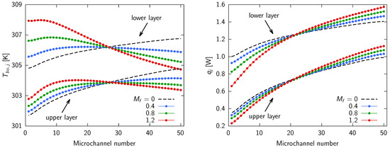
Figure 6.
Cross-flow, double-layered microchannel heat sinks with average velocity and different values of : the outlet mean bulk temperatures (left) and the microchannel heat flow rates (right).
4. Effects of Header Geometry
After proving the validity of the concept of controlling the formation of hotspots using an ideal velocity distribution in the microchannels such that the flow is higher in the microchannels farther from the inlet port, a verification of the performance of the same XF-DL-MCHS when the velocities in the microchannels were determined by the characteristics of the inlet and outlet headers having realistic geometries was conducted.
Figure 7 (left side) depicts the geometry of the analyzed headers, while Figure 7 (right side) illustrates an example of a symmetrical baffle. The baffle, which was designed aiming to create an optimal velocity distribution among the microchannels, is characterized by the semi-length and is placed within the header between the cylindrical inlet port and the inlet of the two microchannel layers.
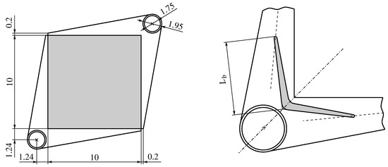
Figure 7.
A plan view and the dimensions, in millimeters, of the XF-DL-MCHS: the basic geometry (left) and the half-length of the baffle placed in the inlet header (right). Figure adapted from [38].
In a previous paper [38], we numerically analyzed the fluid flow in the MCHSs, including the headers and the baffle. The computational domain comprised the two cross-flow microchannel layers, the inlet and outlet headers, and the two sections of the inlet and outlet piping. The core of the heat sink, depicted in Figure 2 (left side) and shaded in gray in Figure 7 (left side), was modeled as a porous medium, and the fluid dynamic calibration coefficients were derived from previous calculations on the same heat sink geometry [39]. The domain was discretized by tetrahedral cells in the piping and headers, as well as by hexahedral cells in the microchannel layers; at the common interfaces between the headers and layers, the grids were non-conformal. An inflation layer, with hexahedral cells of increasing thickness with increasing distance from the wall, was generated at the solid surfaces in the piping and headers. Based on a grid independence study, the number of cells of the adopted grids was larger than 2 million, with slight differences depending on the considered geometry [38]. The fluid used was water, with the same thermophysical properties as those described in Section 2. The simulations were conducted using the ANSYS Fluent software Release 17.0 [43], adopting the Realizable turbulence model because, while the flow in the microchannels is laminar, the one in the headers is turbulent. Further detail regarding the numerical model can be found in reference [38]. The simulations were carried out for three different inlet flow rates, corresponding to average velocities in the microchannels equal to , , and . The velocity distributions at the inlet of the two microchannel layers were numerically calculated, and the degree of maldistribution was assessed using the parameter, as defined in Equation (2).
Table 4 presents a comprehensive overview of the different types and sizes of baffles analyzed in [38], namely solid, cut, and porous. Solid baffles have a height equal to that of the fluid passage in the header, and they can be made of the same material as the heat sink, such as, for example, silicon. Their half-length was equal to , , and 4.5 . The cut baffles were also made of solid material but had a partial height equal to (referred to as Case C1) and (referred to as Case C2) of the height of the header fluid passage in order to offer less resistance to the fluid flow with respect to the full height ones. Their half-length was equal to and 4.5. Porous baffles, with an = 6.5, were full height and made of a porous material such as, for example, a sintered metallic medium made from copper or stainless steel powders [44,45]. They were divided into three equal-length sections characterized by different permeabilities (low, medium, and high), with the lowest values near the inlet port and the highest values at the ends of the baffle. Three different combinations of permeability, referred to as P1, P2, and P3, were investigated, and the corresponding values of permeabilities are reported in Table 5. The permeability values adopted in the different combinations fell within the ranges proposed in the literature for microchannel applications [44,45]. In addition, the case without baffle (NB), which was used as a reference, was also analyzed to identify the effect of the header geometry only.

Table 4.
List of the header geometries with different kinds and sizes of baffles that were analyzed in [38].

Table 5.
Permeability values [m2] for the three porous baffle sections for the P1, P2, and P3 combinations. Table adapted from [38].
The normalized inlet velocity distributions , where j is the j-th microchannel in the layer, were provided for the top and bottom layers in a previous paper [38]. For the sake of completeness, these distributions are also reported in Figure 8 for solid, cut, and porous baffles for the three average velocity values considered. The case without baffle () is displayed, as a reference case, in all figures, with the black dashed and dotted lines representing the top and bottom layers, respectively. The lower the microchannel identification number, the closer it is to the inlet port.
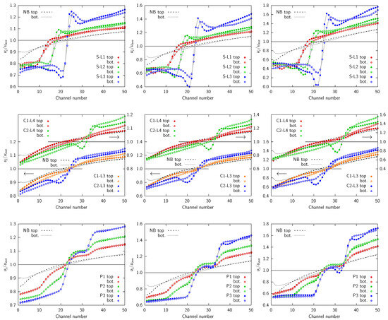
Figure 8.
Effects of the header geometry, i.e., the normalized velocity distributions for the top and bottom microchannel layers for all cases in Table 4 and for the different average velocities: (left) m/s, (center) m/s, and (right) m/s. Figure adapted from [38].
The results indicate that both the header alone and the addition of baffles lead to a nonuniform velocity distribution with higher mass flow rates in the microchannels with higher identification numbers, i.e., those furthest from the inlet port, thus ensuring a positive effect on the hotspot control. A similar velocity distribution was found in the upper and lower layers. It could be concluded that the effect of the geometry on the degree of velocity nonuniformity among the microchannels was amplified if both the baffle half-length and the average velocity in the microchannels increase.
As detailed in [38] and as can be inferred from the top part of Figure 8, solid baffles allow for a pronounced nonuniform distribution, particularly for large values of . However, the velocities in the microchannels are very low just before the baffle ends due to a wide recirculation region at the trailing edges of the baffle. This low-velocity region is followed by a very pronounced peak, resulting in a maldistribution profile that is far from linear. In contrast, cut baffles, i.e., partial height solid baffles, exhibit smoother velocity distributions, although with less pronounced velocity differences, as shown in the middle section of Figure 8. To overcome the limitations of solid and cut baffles, namely to achieve a markedly pronounced nonuniform velocity distribution while maintaining a more regular pattern, we proposed the use of a porous material instead of a solid one in [38]. As can be seen from the bottom section of Figure 8, porous baffles produce nonuniform velocity distributions comparable to those yielded by solid baffles but with smoother, closer-to-linear trends. This result was obtained by subdividing the porous baffles into three equal-length sections, each characterized by a distinct permeability, as detailed in Table 5. To achieve a smoother velocity distribution, the permeability of each baffle section was increased from the center toward the ends. The permeability of the three sections decreased progressively from the case to the case, which presented the largest flow-resistance and therefore the greatest effect on the maldistribution. However, the case also showed a velocity distribution that was far away from linear.
In the present paper, which represents a completion of the previous work [38], the thermal performance of all cases listed in Table 4 were analyzed for the three average velocities in the microchannels that were equal to , , and using the in-house finite element procedure briefly described in Section 2. The boundary conditions and fluid/solid properties were the same as those described in Section 2; the nonuniform inlet velocity profiles in the microchannels of the upper and lower layers were those numerically obtained in [38] and reported in Figure 8.
Figure 9, Figure 10 and Figure 11 illustrate the temperatures at the surface where the heat flow was applied for all the cases listed in Table 4 and for the three average velocities investigated: , , and . For all values of , the hotspot at the corner opposite to that where the cold fluid inlet was located can be clearly seen for the case without baffle (). The high temperature of this hotspot resulted in a significant temperature nonuniformity and in a large thermal resistance of the heat sink. Consequently, the temperature value of this hotspot can be used as a qualitative indicator of the effectiveness of the header- and baffle-induced nonuniform velocity distribution. A brief comparison of the three figures revealed that the same geometry produces increasingly pronounced effects on the temperature distribution as the velocity increases. This is due to the fact that, as previously observed, the velocity nonuniformity is amplified as the average velocity in the microchannels increases.
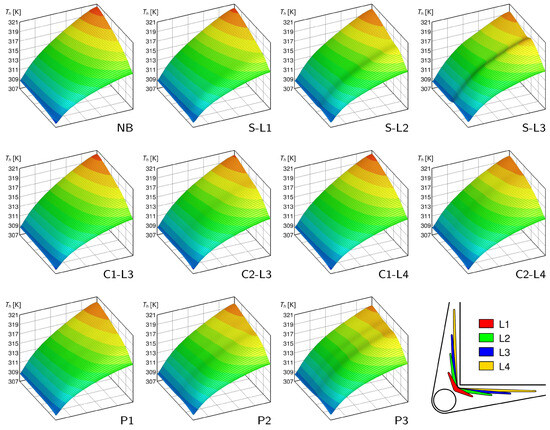
Figure 9.
Effects of the header geometry: heated surface temperature distributions for the geometries listed in Table 4 and where .
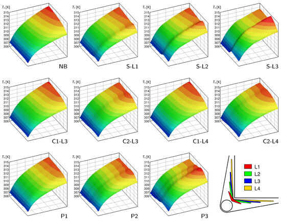
Figure 10.
Effects of the header geometry: heated surface temperature distributions for the geometries listed in Table 4 and where .
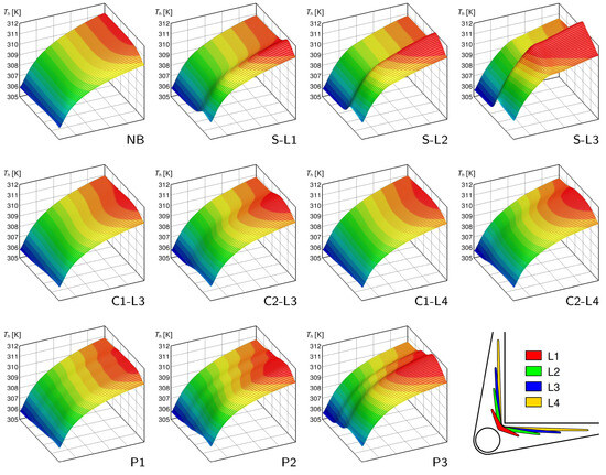
Figure 11.
Effects of the header geometry: heated surface temperature distributions for the geometries listed in Table 4 and where .
It can be observed that, for the case and for all three velocities analyzed, the hotspot temperature value remained lower than that for the so-called case, i.e., the ideal case with uniform velocity distribution and where , as depicted in Figure 3, Figure 4 and Figure 5. This demonstrates that the manifold alone is able to produce a beneficial nonuniform velocity profile, increasing the velocity in the microchannels closer to the outlet port.
As can be seen in Figure 9 for , in the case of a solid baffle (, , and ), the hotspot temperature decreased as the baffle length increased, inducing a more pronounced nonuniform flow distribution. In the case, and particularly in the case, it can be clearly seen that, in addition to the primary hotspot (the one at the corner of the heated surface closest to the outlet port), a secondary hotspot appeared at the exit of the heat sink core, which is at a location close to the entrance of the microchannels of the upper layer. This effect is caused by the valley in the velocity distributions, i.e., the very low velocity values in those microchannels shielded by the baffle and by the recirculation in the header just before the baffle ends, as discussed in [38]. For higher velocities, as can be observed in Figure 10 and Figure 11, the temperature of the secondary hotspot exceeded that of the primary one for the and cases at and for all solid baffles at .
In the case of cut baffles (, , , and ), the effect was small compared to the solution, even with the largest baffle length, . The smooth velocity distribution profile meant that the secondary hotspot, if present, was very weak and comparable to the primary one. For higher velocities, as can be seen in Figure 10 and Figure 11, the temperature of the secondary hotspot exceeded that of the primary one for at and for all cut baffle cases at .
The porous baffle geometries (, , and ) yielded less pronounced secondary hotspots than the solid baffle; for , as shown in Figure 9, the case, i.e., the one with the lowest permeability, gave the lowest hotspot temperature. For , as shown in Figure 10, the most favorable effect was obtained for case despite the formation of a secondary hotspot, and the maximum temperature on the heated surface was the lowest of all the other cases. For case , the temperature of the secondary hotspot exceeded that of the primary hotspot due to the less smooth nonuniform velocity distribution profile induced by the baffle. Finally, for , as shown in Figure 11, the secondary hotspot temperature always exceeded that of the primary hotspot, implying that the degree of flow nonuniformity was too pronounced. The formation of multiple secondary hotspots can be clearly seen for the porous baffle cases, particularly for and at velocities of and , as shown in Figure 10 and Figure 11, respectively. The temperature of these secondary hotspots may exceed that of the primary hotspot, resulting in a reduction in the thermal performance of the heat sink.
To provide further physical insight, for the case of an intermediate velocity taken as an example, the values of the microchannel outlet mean bulk temperatures of the upper and lower layers are shown in Figure 12 for the solid baffle (left side) and the porous baffle (right side) geometries. The cases with cut baffles are not included in the analysis because they produced trends that were very similar to those of the other cases. The no baffle case, , is depicted in Figure 12 with a dashed black line as a reference case. It should be noted that the lower the microchannel identification number on the x-axis, the closer it is to the inlet port. As can be seen, the header alone without a baffle produces a favorable velocity distribution profile as it generates higher velocities in the microchannels further from the inlet port. For all cases, the outlet mean bulk temperatures presented similar trends in the upper and lower layers, but they were higher in the lower one as it is closer to the heated surface.
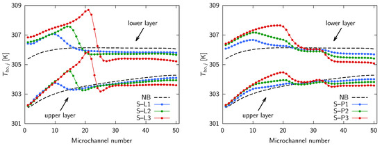
Figure 12.
Outlet mean bulk temperatures for an average velocity : headers with solid baffles (left); and headers with porous baffles (right).
As previously stated, for the solid baffles , , and , the velocities in the microchannels exhibited low values close to the inlet port and markedly low values just before the baffle ended due to the formation of a recirculation zone. Beyond the trailing edges of the baffle, a highly pronounced velocity maximum was observed, followed by large velocity values in the microchannels close to the outlet port. This is consistent with the data presented in Figure 12, where the microchannels with low velocity and, consequently, a lower heat capacity exhibited a higher outlet temperature, while the microchannels with a high velocity displayed a lower outlet temperature. In the the left side of Figure 12, the outlet mean bulk temperatures were higher in the first microchannels close to the inlet port; then, there was a pronounced maximum, and, finally, they decreased significantly in the microchannels close to the outlet port.
These temperature profiles are also consistent with the temperature maps in Figure 10. In fact, the secondary hotspots were a consequence of the presence of microchannels characterized by low fluid velocities and, therefore, high outlet temperatures. Conversely, the low temperatures in the microchannels closest to the outlet port mitigated the primary hotspot. As can be seen in the left side of Figure 12, the maximum values of the outlet temperatures were observed in microchannels situated further and further away from the inlet port as the length of the baffle increased from to . This was due to the fact that the minimum velocity values occur just before the baffle ends, as discussed in [38] and displayed in Figure 8.
Similar conclusions can be drawn with regard to the porous baffle cases , , and , as shown in Figure 12 on the right side. While the outlet mean bulk temperature trends were similar to those observed for the solid baffles, the porous baffles exhibited a much more regular pattern. The different behavior of the three sections of the porous baffles, characterized by different values of permeability, was also evident. In all cases, the baffles ensured a reduction in the temperature of the microchannels close to the outlet port when compared to the scenario without baffles, with a positive impact being observed regarding the temperature of the primary hotspot.
The values of the parameters calculated with Equations (3) and (4) are plotted in Figure 13 against the maldistribution factor and for the three average velocities considered in this study; the temperature uniformity over the heated surface is shown on the left, while the total thermal resistance is shown on the right. For , a decreasing trend of both parameters with was observed, indicating that more uneven velocity distributions provide superior thermal performances. The case, i.e., with the effect of the header alone, showed the highest values, attesting to the positive effect of the baffle from the hotspot control point of view.
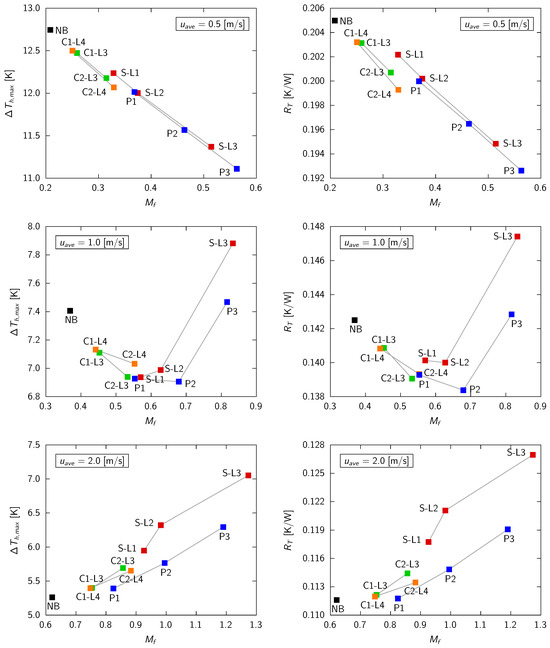
Figure 13.
Thermal performances of the different heat sink headers for different average velocities in the microchannels : vs. (left); and vs. (right).
The header geometries with the lowest thermal resistance and the best thermal uniformity were those with solid and porous baffles, which provided a pronounced velocity nonuniformity in the microchannels. As can be seen from Table 1, for , the optimum value of should be around 1.0. However, even the best performing baffles ( and ) did not allow such high values of to be reached because, as already mentioned, the effect of the baffle was less pronounced at lower velocities. For , it can be observed that and reach a minimum value for case with a value close to . For the smaller values of , the impact on hotspot reduction is less significant. Table 2 indicates that the optimal value was close to , which is comparable to that attained with the and baffles; however, these cases exhibited a velocity distribution that was markedly non-linear, resulting in secondary hotspots, as previously illustrated in Figure 10, leading to a deterioration in the thermal performance. With the exception of the and cases, all other baffle types demonstrated a superior thermal performance compared to the header effect alone (Case ). Finally, for , the degree of nonuniform velocity in the microchannels was very pronounced since the effect of baffles increases at higher velocities. The final outcome was opposite to that of . In fact, an increasing trend of both parameters with was observed, and the case displayed the lowest values, showing that a manifold alone ensures an almost optimal velocity distribution in the microchannels. This could also be inferred from Table 3, which shows that the optimal value of was close to 0.6, a value that was already guaranteed by the header alone. An increase in the parameter led to the development of secondary hotspots, as can be clearly observed in Figure 11.
The results presented in Figure 13 are also confirmed by Table 6, Table 7, and Table 8 for the three average velocities considered in this study, i.e., , , and , respectively. In the tables, the percentage variations , , and of the parameters , , and are reported with respect to the ideal case of a uniform velocity distribution in the microchannels (i.e., Case , corresponding to ), which was taken as a reference. It can be observed that, regardless of the average velocity , the header geometry alone (Case ) ensures a high velocity in the microchannels farthest from the inlet port and a low velocity in the microchannels closest to the inlet port, with a positive effect on the mitigation of the hotspot. Both and were reduced with respect to the case. For instance, the resistance was reduced by , , and for , , and , respectively. On the other hand, the pressure losses were increased due to the unavoidable fluid dynamic resistance of the header. It is important to note that, for Case , the pressure losses are only those in the microchannels and do not include the effect of a header, which is always present in a real heat sink.

Table 6.
Values of the thermal and hydraulic performance parameters for and the different heat sink header cases.

Table 7.
Values of the thermal and hydraulic performance parameters for and the different heat sink header cases.

Table 8.
Values of the thermal and hydraulic performance parameters for and the different heat sink header cases.
As previously illustrated in Figure 13, the optimal thermal performance was observed for Baffle at and at , with a reduction in the thermal resistance of and , respectively. Conversely, at , all the baffles exhibited worse thermal performances with respect to the case of a header without a baffle (). It was evident that the presence of the baffle results in a notable increase in pressure drop. In particular, the increases by for the optimum Case at and by for the optimum Case at . However, when the increase in pressure drop was calculated with respect to the geometry, which takes into account the unavoidable effect of the manifold alone, the increases due to the baffle were found to be for Case at and for Case at .
Finally, the data presented in Table 6, Table 7 and Table 8 are consistent with the conclusions drawn in Section 3 concerning the effect of a linear variation of velocity among the microchannels. It can be seen that, for each value of , there is an optimal value of that yields the best performance corresponding to the minimum of the thermal resistance and also to the maximum of the temperature uniformity over the heated surface. It is apparent that, as the velocity increases, the optimal degree of velocity nonuniformity decreases. At low flow rates (), the baffles analyzed in [38] did not allow for the achievement of optimal values, despite the fact that they ensured an improvement in the thermal performance. Conversely, at intermediate velocities (), it is possible to attain optimum values with the realistic header geometries and baffles proposed in [38]. At high flow rates (), the header alone is able to generate an almost optimal velocity nonuniformity. Nevertheless, if not properly designed, real header geometries may produce deviations from the ideal linear velocity distribution in microchannels, which could lead to the development of secondary hotspots and a subsequent degradation in thermal performance.
5. Comparison with the Counterflow Configuration
As has already been pointed out, it is well established that a double-layered microchannel heat sink with a counterflow configuration (CF-DL-MCHS) is capable of providing effective thermal performance. However, it requires the use of geometrically complex headers with two inlet and two outlet ports, as shown in Figure 14 (left side). On the other hand, the double-layered microchannel heat sink with a cross-flow configuration (XF-DL-MCHS) analyzed in the previous sections requires much simpler headers with only one inlet and one outlet port, as can be seen in Figure 1 (left side).
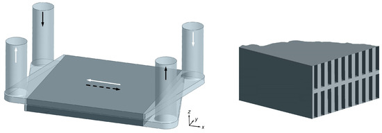
Figure 14.
A Counterflow double-layered microchannel heat sink: the overall geometry including headers (arrows indicate flow direction in microchannel layers and dotted line corresponds to bottom layer) (left); and the detail showing microchannel positions in the two parallel layers (right).
In order to compare the thermal performance of the counterflow and cross-flow configurations, the CF-DL-MCHS depicted in Figure 14 (left side) was numerically investigated. The geometry and operative conditions of both the microchannel layers were identical to those described in Section 2 for the cross-flow configuration. The sole difference was that, for the counterflow configuration, the microchannels in the top and bottom layers were parallel, as can be seen in Figure 14 (right side).
The header geometry for both the top and bottom layers was derived from that of the XF-DL-MCHS shown in Figure 7 (left side). The diameter of the inlet and outlet ports were the same for both cross-flow and counterflow configurations. As can be observed in Figure 14 (left side), the header inlet/outlet configuration was of the Z-type [29] to allow for the simultaneous feeding of both layers from above. This would not have been feasible with a central piping I-type header geometry.
The same numerical methodology described in [38] was employed to derive the velocity distributions in both the top and bottom microchannel layers of the CF-DL-MCHS using ANSYS Fluent, Release 2023 R2 [46]. The normalized inlet velocity distributions , where j is the j-th microchannel in the layer, are given in Figure 15 for the same three average velocity values investigated for the cross-flow configuration. The lower the microchannel identification number, the closer it is to the inlet port. As the head geometry was substantially identical for the top and bottom layers, only a single microchannel velocity distribution was provided for each velocity value. As can be seen, the velocities were lower in the microchannels close to the inlet port and higher in those close to the outlet port. As previously observed, the velocity nonuniformity was amplified as the average velocity in the microchannels increased.
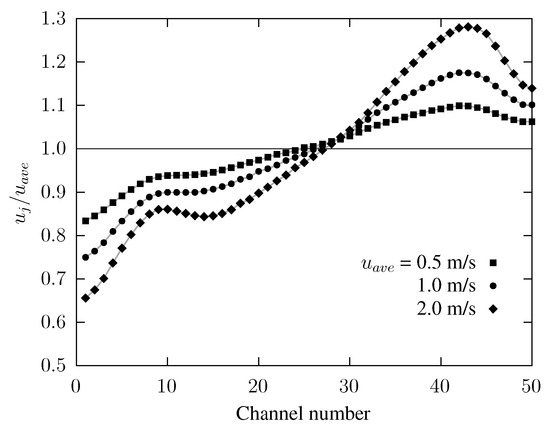
Figure 15.
Normalized velocity distributions for the CF-DL-MCHS with different average velocities .
A thermal analysis of the heat sink core in the counterflow configuration was carried out following the same numerical procedure outlined in Section 2. Two inlet velocity profiles were considered: a uniform one (), which served as a reference case and will be referred to as Case MF0-CF; and the one provided in Figure 15, which was induced by the header and will be referred to as Case HD-CF (HeaDer CounterFlow). Cases MF0-CF and HD-CF for the counterflow configuration correspond to Cases MF0 and for the cross-flow configuration, respectively.
Figure 16 and Figure 17 illustrate the temperatures at the surface where the heat flux was applied for Cases MF0-CF and HD-CF, respectively, and for the three average velocities investigated. The fluid flows from left to right in the bottom layer and from right to left in the top layer, as shown in Figure 14 (left side). In the case of uniform velocity distribution (Figure 16), the expected temperature distribution produced by the counterflow configuration could be observed, with the maximum temperature values close to the exit of the bottom layer. Since all microchannels have the same mass flow rate, the temperature profile was the same in the corresponding position of each microchannel.
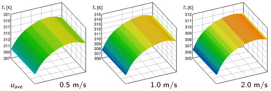
Figure 16.
Heated surface temperature distributions for the counterflow configuration with uniform velocity distribution (Case MF0-CF): (left); (middle); and (right).
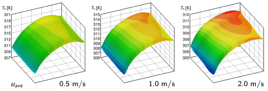
Figure 17.
Heated surface temperature distributions for the counterflow configuration with velocity nonuniformity induced by the header (Case HD-CF): (left); (middle); and (right).
As can be seen from Figure 17, the uneven velocity distribution induced by the headers is not favorable from a thermal point of view, as was the case for the XF-DL-MCHS. The low-velocity values in the microchannels near the inlet ports produce higher maximum temperatures in the areas of the heated surface corresponding to the channels close to the sides of the heat sink. As with the XF-DL-MCHS, the temperature of the resulting hotspot can be used as an indicator of the effect of the nonuniform velocity distribution induced by the header. A brief comparison of the temperature distributions for the same mass flow rates between Figure 16 and Figure 17 reveals that the header produces increasingly pronounced effects on the temperature distribution as the average velocity increases. This is due to the fact that, as previously observed, the velocity nonuniformity is amplified as the mass flow rate in the microchannels increases.
Table 9 shows the values of the parameters of , , , and for both Cases MF0-CF and HD-CF, as well as for , , and . As can be seen, the effect of velocity nonuniformity due to the header is to worsen the thermal performance, i.e., to increase both the maximum temperature difference over the heated surface and the thermal resistance for Case with respect to Case MF0-CF. The effect is smaller at low flow rates (i.e., the thermal resistance increases by 3.6% for while the pressure drops by 20.2%) and larger at high flow rates (the thermal resistance increases by 5.5% for while the pressure drops by 53.0%). It is important to note that, for Case MF0-CF, the pressure losses are only those in the microchannels and do not include the effect of a header, which is always present in a real heat sink.

Table 9.
Values of the thermal and hydraulic performance parameters for counterflow configuration and for different values of .
Finally, Table 10 compares the performance of the cross-flow configuration and the counterflow configuration, which exhibited superior thermal behavior for the uniform velocities in the microchannels. The table shows the percentage differences in the thermal performance parameters and the pressure drop with respect to the counterflow Case for the cross-flow cases emphasized in bold in Table 1, Table 2 and Table 3 and Table 6, Table 7 and Table 8. The cross-flow cases considered are those with the lowest thermal resistance and the best thermal uniformity for a linear velocity distribution, as identified in Section 3 (Table 1, Table 2 and Table 3), as well as in Section 4 for the nonuniform distributions induced by realistic header geometries (Table 6, Table 7 and Table 8).

Table 10.
Values of the thermal and hydraulic performance parameters for the cross-flow configuration and for the different values of with respect to Case HD-CF (the cases labeled “linear” in the table refer to a linear velocity distribution).
It can be observed that the thermal performance of the XF-DL-MCHSs with appropriate headers is comparable to that of the counterflow configuration, particularly at intermediate and high mass flow rates. However, this was achieved at the expense of higher pressure drops, particularly at low flow rates. Concerning the pressure drop comparisons, it is important to note that, for the “linear” cases, the effect of the headers was not taken into account, whereas it was for the reference Case HD-CF.
6. Conclusions
The thermal performance of a cross-flow, double-layered microchannel heat sink was numerically investigated using an in-house finite element procedure for the solution of the parabolized form of the Navier–Stokes equations in the microchannels and the elliptic form of the thermal energy equation in the whole computational domain.
First, the investigation focused on the thermal performance attainable under an ideal condition corresponding to a linear velocity variation among the microchannels. Then, the thermal effect achievable in practice with realistic headers with baffles was assessed. Finally, the more common counterflow configuration for a DL-MCHS was also numerically investigated to compare the thermal performance with that of the cross-flow configuration.
Three different values of the coolant volumetric flow rate were considered, corresponding to the average velocities in the microchannels of , , and . A uniform specific heat flux was applied to the heated surface, while all other surfaces of the heat sink were assumed to be adiabatic. It should be noted that the present study was not intended as a comprehensive design or optimization of an actual device but rather as a proof of concept.
Thermal results were presented in terms of the maximum temperature difference over the heated surface, which gives a measure of the temperature uniformity, as well as of the total thermal resistance of the heat sink. The main outcomes of this study are presented below.
- For each flow rate, an optimal degree of linear velocity nonuniformity among the microchannels existed that yielded the best thermal performance, corresponding to the minimum thermal resistance and the temperature difference over the heated surface. As the flow rate increases, the appropriate degree of nonuniformity decreases. For example, with the optimal velocity distribution, the thermal resistance was only 3.4%, 1.8%, and 0.3% higher than that of the counterflow configuration for average microchannel velocities equal to 0.5, 1, and 2 m/s, respectively, and it was reduced by 11.8%, 7.1%, and 4.4% compared to the case with uniform inlet velocities.
- Realistic baffle geometries at low flow rates do not allow one to achieve optimal nonuniformity, although they do improve thermal performance; at intermediate flow rates, they are able to yield optimal maldistribution values, while, at high flow rates, the header alone can generate an almost optimal velocity nonuniformity.
- The formation of secondary hotspots and the subsequent degradation in thermal performance were observed when the velocity nonuniformity exhibited a far-from-linear distribution. In the design of a proper header, possibly with a baffle, it is of the great importance to ensure a velocity distribution that is both nonuniform and as smooth as possible.
In conclusion, this research demonstrates that a cross-flow DL-MCHS, with its simpler headers and piping, can achieve performance levels that are very close to those of a counterflow DL-MCHS that requires more complex header geometry. This outcome was achieved through the proper design of headers, which ensures a suitable velocity nonuniform distribution among the microchannels.
Since, as shown here, the optimal velocity distribution depends on the geometry and the total mass flow rate, each device and each operating condition needs to be analyzed separately. Thus, the integration of the heat transfer model for microchannel layers treated as porous media in a commercial code, such as ANSYS Fluent, would represent a potential future development for overcoming the limitations of the numerical approach adopted in this work. In fact, this approach could enable the analysis of more complex geometries and realistic heat flux distributions with limited computational resources, and it would also allow for the concept proposed in this paper, namely the mitigation of hotspots through an appropriate velocity distribution in the microchannels, to be applied to the design and optimization of actual devices.
Furthermore, the simultaneous study of the hydrodynamic and thermal behavior of both the headers and the heat sink would allow quantification of the parasitic heat transfer that necessarily occurs outside a counterflow DL-MCHS core where the inlet and outlet headers are adjacent to each other.
Author Contributions
Conceptualization, S.S. and C.N.; methodology, S.S. and C.N.; software, S.S. and C.N.; validation, S.S.; data curation, S.S. and C.N.; writing—original draft preparation, S.S. and C.N.; visualization, S.S. All authors have read and agreed to the published version of the manuscript.
Funding
This research received no external funding.
Data Availability Statement
The original contributions presented in this study are included in the article; further inquiries can be directed to the corresponding authors.
Conflicts of Interest
The authors declare no conflicts of interest.
References
- Tuckerman, D.B.; Pease, R.F.W. High-performance heat sinking for VLSI. IEEE Electron Device Lett. 1981, 2, 126–129. [Google Scholar] [CrossRef]
- Adham, A.M.; Mohd-Ghazali, N.; Ahmad, R. Thermal and hydrodynamic analysis of microchannel heat sinks: A review. Renew. Sustain. Energy Rev. 2013, 21, 614–622. [Google Scholar] [CrossRef]
- He, Z.; Yan, Y.; Zhang, Z. Thermal management and temperature uniformity enhancement of electronic devices by micro heat sinks: A review. Energy 2021, 216, 119223. [Google Scholar] [CrossRef]
- Yu, Z.-Q.; Li, M.-T.; Cao, B.-Y. A comprehensive review on microchannel heat sinks for electronics cooling. Int. J. Extreme Manuf. 2024, 6, 022005. [Google Scholar] [CrossRef]
- Hajialibabaei, M.; Saghir, M.Z. A critical review of the straight and wavy microchannel heat sink and the application in lithium-ion battery thermal management. Int. J. Thermofluids 2022, 14, 100153. [Google Scholar] [CrossRef]
- Dwivedi, A.; Khan, M.M.; Pali, H.S. A comprehensive review of thermal enhancement techniques in microchannel heat exchangers and heat sinks. J. Therm. Anal. Calorim. 2023, 148, 13189–13231. [Google Scholar] [CrossRef]
- Japar, W.M.A.A.; Sidik, N.A.C.; Saidur, R.; Asako, Y.; Nurul Akmal Yusof, S. A review of passive methods in microchannel heat sink application through advanced geometric structure and nanofluids: Current advancements and challenges. Nanotechnol. Rev. 2020, 9, 1192–1216. [Google Scholar] [CrossRef]
- Zhou, J.; Cao, X.; Zhang, N.; Yuang, Y.; Zhao, X.; Hardy, D. Micro-channel heat sink: A review. J. Therm. Sci. 2020, 29, 1431–1462. [Google Scholar] [CrossRef]
- Vafai, K.; Zhu, L. Analysis of two-layered micro-channel heat sink concept in electronic cooling. Int. J. Heat Mass Transf. 1999, 42, 2287–2297. [Google Scholar] [CrossRef]
- Xu, Y.; Gong, L.; Li, Y.; Bai, Z.; Xu, M. Thermal performance and mechanics characteristic for double layer microchannel heat sink. J. Therm. Sci. 2019, 28, 271–282. [Google Scholar] [CrossRef]
- Xie, G.; Liu, Y.; Sunden, B.; Zhang, W. Computational study and optimization of laminar heat transfer and pressure loss of double-layer microchannels for chip liquid cooling. J. Therm. Sci. Eng. Appl. 2013, 5, 011004. [Google Scholar] [CrossRef]
- Wu, J.M.; Zhao, J.Y.; Tseng, K.J. Parametric study on the performance of double-layered microchannels heat sink. Energy Convers. Manag. 2014, 80, 550–560. [Google Scholar] [CrossRef]
- Hung, T.-C.; Yan, W.-M.; Li, W.-P. Analysis of heat transfer characteristics of double-layered microchannel heat sink. Int. J. Heat Mass Transf. 2012, 55, 3090–3099. [Google Scholar] [CrossRef]
- Kulkarni, K.; Khan, A.A.; Kim, K.-Y. Performance analysis of double-layer microchannel heat sink with various microchannel shapes. Heat Transf. Res. 2018, 49, 349–368. [Google Scholar] [CrossRef]
- Lin, L.; Chen, Y.-Y.; Zhang, X.-X.; Wang, X.-D. Optimization of geometry and flow rate distribution for double-layer microchannel heat sink. Int. J. Therm. Sci. 2014, 78, 158–168. [Google Scholar] [CrossRef]
- Leng, C.; Wang, X.-D.; Wang, T.-H.; Yan, W.-M. Optimization of thermal resistance and bottom wall temperature uniformity for double-layered microchannel heat sink. Energy Convers. Manag. 2015, 93, 141–150. [Google Scholar] [CrossRef]
- Shen, H.; Zhang, Y.; Wang, C.-C.; Xie, G. Comparative study for convective heat transfer of counter-flow wavy double-layer microchannel heat sinks in staggered arrangement. Appl. Therm. Eng. 2018, 137, 228–237. [Google Scholar] [CrossRef]
- Sharma, D.; Singh, P.P.; Garg, H. Numerical analysis of trapezoidal shape double layer microchannel heat sink. Int. J. Mech. Eng. 2013, 3, 10–15. [Google Scholar] [CrossRef]
- Wong, K.C.; Ang, M.L. Thermal hydraulic performance of a double-layer microchannel heat sink with channel contraction. Int. Commun. Heat Mass Transf. 2017, 81, 269–275. [Google Scholar] [CrossRef]
- Borah, S.; Tamuli, B.R.; Bhanja, D. Thermohydraulic performance intensification of wavy, double-layered microchannel heat sink with height tapering. J. Thermophys. Heat Transf. 2023, 37, 119–132. [Google Scholar] [CrossRef]
- Zhai, Y.; Li, Z.; Wang, H.; Xu, J. Analysis of field synergy principle and the relationship between secondary flow and heat transfer in double-layered microchannels with cavities and ribs. Int. J. Heat Mass Transf. 2016, 101, 190–197. [Google Scholar] [CrossRef]
- Chein, R.; Chen, J. Numerical study of the inlet/outlet arrangement effect on microchannel heat sink performance. Int. J. Therm. Sci. 2009, 48, 1627–1638. [Google Scholar] [CrossRef]
- Chu, W.-X.; Ma, T.; Zeng, M.; Qu, T.; Wang, L.-B.; Wang, Q.-W. Improvements on maldistribution of a high temperature multi-channel compact heat exchanger by different inlet baffles. Energy 2014, 75, 104–115. [Google Scholar] [CrossRef]
- Said, S.A.M.; Ben-Mansour, R.; Habib, M.A.; Siddiqui, M.U. Reducing the flow mal-distribution in a heat exchanger. Comput. Fluids 2015, 107, 1–10. [Google Scholar] [CrossRef]
- Liu, X.; Yu, J. Numerical study on performances of mini-channel heat sinks with non-uniform inlets. Appl. Therm. Eng. 2016, 93, 856–864. [Google Scholar] [CrossRef]
- Wei, X.; Joshi, Y.; Patterson, M.K. Experimental and numerical study of a stacked microchannel heat sink for liquid cooling of microelectronic devices. ASME J. Heat Transf. 2007, 129, 1432–1444. [Google Scholar] [CrossRef]
- Xie, G.; Li, S.; Sunden, B.; Zhang, W. Computational fluid dynamics for thermal performance of a water-cooled minichannel heat sink with different chip arrangements. Int. J. Numer. Methods Heat Fluid Flow 2014, 24, 797–810. [Google Scholar] [CrossRef]
- Satheeshkumar, M.; Thansekhar, M.; Pandiyarajan, R. Examining the impact of inlet header configurations on wavy microchannel heat sinks. Heat Mass Transf. 2023, 59, 1805–1819. [Google Scholar] [CrossRef]
- Xia, G.D.; Jiang, J.; Wang, J.; Zhai, Y.L.; Ma, D.D. Effects of different geometric structures on fluid flow and heat transfer performance in microchannel heat sinks. Int. J. Heat Mass Transf. 2015, 80, 439–447. [Google Scholar] [CrossRef]
- Ghani, I.A.; Sidik, N.A.C.; Kamaruzzaman, N.; Yahya, W.J.; Mahian, O. The effect of manifold zone parameters on hydrothermal performance of micro-channel Heat Sink: A review. Int. J. Heat Mass Transf. 2017, 109, 1143–1161. [Google Scholar] [CrossRef]
- Hempijid, T.; Kittichaikarn, C. Effect of heat sink inlet and outlet flow direction on heat transfer performance. Appl. Therm. Eng. 2020, 164, 114375. [Google Scholar] [CrossRef]
- Awais, A.A.; Kim, M.-H. Experimental and numerical study on the performance of a minichannel heat sink with different header geometries using nanofluids. Appl. Therm. Eng. 2020, 171, 115125. [Google Scholar] [CrossRef]
- Lin, Y.; Luo, Y.; Li, W.; Cao, Y.; Tao, Z.; Shih, T.I.-P. Single-phase and two-phase flow and heat transfer in microchannel heat sink with various manifold arrangements. Int. J. Heat Mass Transf. 2021, 171, 121118. [Google Scholar] [CrossRef]
- Elqady, H.I.; Abo-Zahhad, E.M.; Ali, A.Y.M.; Elkady, M.F.; El-Shazly, A.H.; Radwan, A. Header impact assessment of double-layer microchannel heat sink in the computational fluid mechanics simulation for CPV thermal management. Energy Rep. 2020, 6, 55–60. [Google Scholar] [CrossRef]
- Ansari, D.; Kim, K.-Y. Double-layer microchannel heat sinks with transverse flow configurations. J. Electron. Packag. 2016, 138, 031005. [Google Scholar] [CrossRef]
- Ansari, D.; Kim, K.-Y. Performance analysis of double-layer microchannel heat sinks under non-uniform heating conditions with random hotspots. Micromachines 2017, 8, 54. [Google Scholar] [CrossRef]
- Nonino, C.; Savino, S. Effects of Non-Uniform Flow Distribution In Double-Layered Cross-Flow Microchannel Heat Sinks. In Proceedings of the Second Pacific Rim Thermal Engineering Conference, Maui, HI, USA, 13–17 December 2019. Paper No. PRTEC-24191. [Google Scholar]
- Nonino, C.; Savino, S. Header shape effect on the inlet velocity distribution in cross-flow double-layered microchannel heat sinks. Fluids 2022, 7, 7. [Google Scholar]
- Nonino, C.; Savino, S. Temperature uniformity in cross-flow double-layered microchannel heat sinks. Fluids 2020, 5, 143. [Google Scholar] [CrossRef]
- Nonino, C.; Savino, S.; Del Giudice, S. FEM for the 3-D analysis of conjugate conduction-convection heat transfer in cross-flow micro heat exchangers. Int. J. Numer. Methods Heat Fluid Flow 2015, 25, 1322–1339. [Google Scholar] [CrossRef]
- Nonino, C.; Savino, S. Numerical investigation on the performance of cross-flow micro heat exchangers. Int. J. Numer. Methods Heat Fluid Flow 2016, 26, 745–766. [Google Scholar] [CrossRef]
- Brandner, J.J.; Henning, T.; Schygulla, U.; Wenka, A.; Zimmermann, S.; Schubert, K. Comparison of crossflow micro heat exchangers with different microstructure designs. In Proceedings of the Third International Conference on Microchannels and Minichannels, Toronto, ON, Canada, 13–15 June 2005. Paper No. ICMM2005-75072. [Google Scholar]
- ANSYS, Inc. Ansys Fluent User’s Guide; Release 17.0; ANSYS, Inc.: Southpointe, PA, USA, 2016. [Google Scholar]
- Chuan, L.; Wang, X.D.; Wang, T.H.; Yan, W.M. Fluid flow and heat transfer in microchannel heat sink based on porous fin design concept. Int. Commun. Heat Mass Transf. 2015, 65, 52–57. [Google Scholar] [CrossRef]
- Singh, R.; Akbarzadeh, A.; Mochizuki, M. Sintered porous heat sink for cooling of high-powered microprocessors for server applications. Int. J. Heat Mass Transf. 2009, 52, 2289–2299. [Google Scholar] [CrossRef]
- ANSYS, Inc. Ansys Fluent User’s Guide; Release 2023 R2; ANSYS, Inc.: Southpointe, PA, USA, 2023. [Google Scholar]
Disclaimer/Publisher’s Note: The statements, opinions and data contained in all publications are solely those of the individual author(s) and contributor(s) and not of MDPI and/or the editor(s). MDPI and/or the editor(s) disclaim responsibility for any injury to people or property resulting from any ideas, methods, instructions or products referred to in the content. |
© 2024 by the authors. Licensee MDPI, Basel, Switzerland. This article is an open access article distributed under the terms and conditions of the Creative Commons Attribution (CC BY) license (https://creativecommons.org/licenses/by/4.0/).