Abstract
The current inverter control strategies have limitations in suppressing grid resonance, especially in complex grid environments with high penetration of renewable energy sources. These strate-gies often focus on suppressing resonance at a single frequency point, but their effectiveness is constrained when dealing with multi-band resonance or dynamically changing grid conditions. The study investigates the application of parallel-operated inverters in the grid, particularly their impact on grid stability. A novel active damping strategy is developed to enhance the grid’s dynamic response and suppress grid resonance. The effectiveness of the control strategy is verified through simulation by establishing Norton equivalent circuit models for multiple in-verters. Fast Through simulation, this study comprehensively evaluates the performance and adaptability of the strategy under various conditions. Results demonstrate that implementing the active damping strategy increases the inverter output power from 9.5 kW to 10 kW, an im-provement of 5.26%. System response time is reduced from 50 ms to 30 ms, and post-stabilization fluctuations decrease to 1.5%. These data conclusively prove the effectiveness of the control strategy in enhancing grid stability and reducing resonance effects. The findings underscore the potential of active damping strategies in improving grid performance and in-verter efficiency. However, further research and optimization are necessary to assess the adapt-ability of these strategies under different grid conditions.
1. Introduction
In the current energy transition and grid modernization process, multi-machine grid-connected inverters [1], as one of the key technologies, play an important role in the development of distributed generation, microgrids, and smart grids [2]. For example, Barkat et al. (2020) [3] proposed a hybrid islanding detection method for multi-single-phase photovoltaic inverters, combining four active methods and three passive methods. These inverters effectively convert renewable energy sources such as solar and wind energy and integrate them into the grid [4], contributing to the improvement of energy utilization efficiency and system reliability [5]. However, in practical applications, the multi-inverter grid connection often faces resonance problems, especially when they do not share the same direct current (DC) power source [6]. Resonance not only affects the quality of electrical energy but may also lead to issues of system stability and equipment safety [7]. In the context of current energy transition and grid modernization, the proliferation and development of multi-inverter grid-connection technology bring new challenges and opportunities to power systems [8]. Traditional single-inverter systems can no longer meet the growing demand for renewable energy integration. Multi-inverter systems, which enable the coordinated grid connection of multiple energy sources, are gradually becoming a key part of the solution [9]. However, due to the complex interactions and differing control strategies among multiple inverters, system resonance issues have become a major obstacle to their stability and operational reliability [10].
In multi-machine grid-connected systems, factors such as inconsistent control strategies, electrical parameter disparities, or differences in system impedance characteristics can easily cause or exacerbate resonance phenomena in the power system [11]. These resonance problems may result in a decreased inverter performance or even equipment damage [12], thus requiring effective technical means for suppression [13]. Active damping-based resonance suppression strategies provide a solution that can effectively control resonance without sacrificing the system dynamic performance [14] and energy efficiency, ensuring the stable operation of power systems [15]. Therefore, researching active damping resonance suppression strategies applicable to multi-inverter grid-connected systems [16] with independent DC power sources holds important theoretical and practical significance [17].
The goal of this study is to design and validate an active damping resonance sup-pression strategy for multi-inverter grid-connected systems with independent DC power sources [18]. Through detailed theoretical analysis and model construction, this study delves into the interaction between inverters and the mechanisms causing resonance in grid-connected systems. The main contributions and novelty of this research lie in the establishment of an accurate power system model, providing an in-depth analysis of the interaction mechanisms between inverters and their impact on resonance issues. An innovative active damping control strategy is proposed, combining theoretical analysis and numerical simulation, which can effectively suppress resonant oscillations in power systems. Detailed simulation verification has confirmed that the proposed strategy has robustness and adaptability under different operating conditions, ensuring its high efficiency and stability in complex networks and various load conditions. These contributions not only fill the research gap on resonance suppression in multi inverter power generation systems in existing literature, but also provide important theoretical and practical guidance for further research and application in related fields.
2. Literature Review
In multi-machine grid-connected inverter systems, resonance is a key factor affecting system stability and power quality [19]. Existing studies have shown that, when multiple inverters are connected to the grid, inconsistencies in control strategies, differences in parameter settings, and mismatches in system impedance characteristics can easily trigger low-frequency and high-frequency resonance phenomena in the system [20]. For instance, Jurkov et al. (2020) [21] pointed out in their research that, when inverters share the same power source, effective control of system resonance can be achieved through appropriate synchronization and impedance matching. However, when inverters use independent DC power sources, the complexity of control significantly increases, and the difficulty of resonance suppression also escalates. Additionally, Jiang and Konstantinou (2023) [22] showed, through simulating different network conditions, that slight variations in grid impedance could trigger resonance states in the system, leading to an unstable inverter performance.
Active damping technology, as an effective method for resonance suppression, has been widely applied in many studies [23]. Active damping intervenes in the system using auxiliary devices such as power system stabilizers, dynamic voltage restorers, and active power filters to suppress resonance by dynamically adjusting grid impedance characteristics [24]. For example, Babu et al. (2020) [25] demonstrated the effectiveness of power system stabilizers in reducing system resonance. By adjusting the inverter control strategy, they enhanced the system’s resistance to frequency fluctuations. In contrast, Wang et al. (2023) [26] utilized active power filter technology in their research to directly suppress harmonics caused by inverter operations, improving power quality. Meraj et al. (2022) [27] proposed a novel filter-less active/reactive power management method that compensated reactive power by precisely eliminating harmonics in the grid system. Case study results showed that the proposed control method effectively reduced system harmonics and maintained power factor close to unity. Li et al. (2023) [28] improved the mathematical model construction process of a multi-inverter grid-connected system powered by multiple independent DC sources. Xue et al. (2022) [29] proposed an adaptive active damping method to eliminate resonance effects. This method treated the system based on a model predictive controller as a closed-loop system for the grid-side current, where the active damping composed of virtual resistance and virtual capacitance effectively suppressed resonance peaks. Cai et al. (2020) [30] introduced a novel first-order active disturbance rejection active damping control strategy for inverter-side current feedback. Zhang et al. (2024) [31] derived the resonance suppression domain of a DC distribution network based on the changes in node impedance before and after resonance suppression. Additionally, they proposed a DC active damper control strategy based on resonance suppression strategy evaluation, which could suppress resonance in various scenarios by specifically designing shaping admittance parameters.
Although active damping technology has been proven effective in controlling resonance in grid-connected inverter systems, most existing research focuses on systems with a shared single DC source [32,33]. This study aims to explore active damping strategies suitable for such systems through systematic theoretical analysis and simulation modeling, aiming to provide new ideas and methods for solving resonance problems in these systems. Therefore, the innovation and main contribution of this study lie in proposing an active damping strategy specifically targeting grid stability in parallel inverter systems. This strategy effectively suppresses grid resonance through precise signal analysis and dynamic adjustment mechanisms, significantly enhancing the system’s dynamic response capability and stability.
3. Research Methodology
3.1. Establishment of System Model
When establishing the mathematical model of a multi-inverter grid-connected system powered by multiple independent DC sources, it is essential to accurately describe the electrical characteristics of each component and their interactions. Figure 1 illustrates the topology of a multi-inverter parallel grid-connected system. In this system, each of the N distributed power sources is connected to an inverter at its output terminal. The output of each inverter is connected to the grid’s common coupling point through an Inductor-Capacitor-Inductor (LCL) filter. This configuration helps reduce harmonic interference and improve power quality. Ultimately, the output currents of all inverters converge on a shared busbar, which is then uniformly input into the grid.
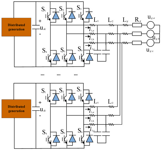
Figure 1.
Topology of multi-inverter parallel grid-connected system.
The LCL filter is a critical component, consisting of two inductive elements (L) and one capacitive element (C), installed, respectively, at the inverter side and the grid side. Its purpose is to reduce the high-frequency components in the output current, thereby lowering harmonic effects. The design and parameter selection of the filter have a direct impact on the stability and performance of the system. The parameter selection for the LCL filter is based on industry standard practices and optimized according to the specific objectives of this study. The goal of this study is to ensure that the total harmonic distortion (THD) of the inverter output current remains at a low level while minimizing the cost and size of the filter. The LCL filter is designed to effectively suppress high-order harmonics generated by the inverter, with the inductor and capacitor values carefully calculated based on the expected harmonic frequency range. To avoid resonance phenomena, the parameters of the LCL filter need to be optimized to ensure system stability under different operating conditions. The optimal combination of inductance and capacitance is determined through simulation analysis.
In Figure 1, the outputs of each inverter are connected to the grid through inductance and filter capacitor C, and then coupled to the grid side inductance . The grid impedance consists of grid-side resistance and inductance . The distribution of current and voltage is as follows: is the current flowing through the grid-side inductance of the filter; is the current flowing through the inverter-side inductance; is the current flowing through the inductance at the inverter output terminal; represents the voltage of the three-phase grid; is the voltage at the point of common coupling; is the voltage across the capacitor; is the output voltage of the three-phase inverter bridge; and is the voltage on the DC side.
An equivalent impedance model is applied to simplify the analysis of the multi-inverter interconnected system. The dynamic and static behavior of the system can be analyzed and calculated using simple methods from circuit theory. The advantage of the model lies in its flexibility and intuitiveness, especially in handling changes in grid impedance. By directly adjusting the model parameters, the system analysis can be quickly updated, thus achieving adaptation to different operating conditions.
The equivalent impedance model typically includes the internal impedance of the inverter, the impedance of the LCL filter, and the sum of the impedance at the grid side. This model helps analyze the interaction between inverters and the overall system response to external disturbances, as calculated by Equation (1):
In Equation (1), represents the internal impedance of the inverter, is the impedance of the LCL filter, and represents the impedance at the grid side.
This model can effectively predict and analyze the behavior of grid-connected inverters under different operating conditions, especially when there are changes in grid impedance. It can provide real-time and accurate feedback, helping optimize control strategies and system design. This approach not only improves the efficiency of the system operation but also ensures power quality and system stability.
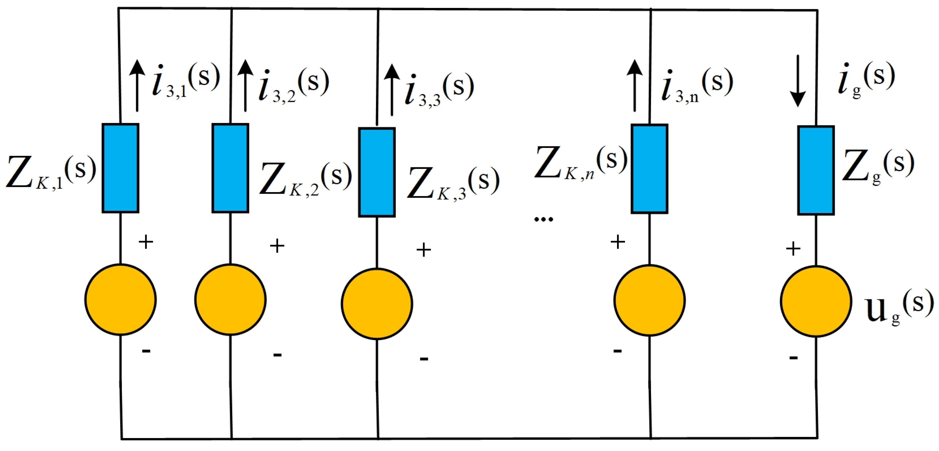
To assess the impact of multiple parallel inverters on grid voltage stability, an experiment constructs a simplified mathematical model. Based on the Thevenin equivalent circuit of a single inverter, a Thevenin equivalent circuit model incorporating multiple inverters is proposed. Since the Thevenin model centers around a voltage source, it is highly suitable for describing the behavior of inverters as voltage sources for the grid. This model intuitively reflects the interaction between inverter output voltage characteristics and the grid, particularly offering a natural advantage in analyzing voltage stability during parallel inverter operation. Furthermore, in inverter control system design, the Thevenin model simplifies the implementation of control algorithms. By equating the inverter output to a voltage source and series impedance, this study facilitates the design of active damping strategies to effectively suppress resonance frequencies and enhance system stability. In the fields of power electronics and power systems, the Thevenin model is widely accepted and used due to its intuitiveness and universality. It is applicable not only to static analysis but also to dynamic system modeling, especially in studying resonance phenomena and dynamic response characteristics. When N inverters operate simultaneously, the equivalent circuit of the system is shown in Figure 2.
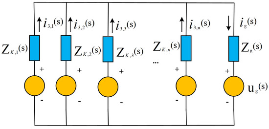
Figure 2.
Topology of multi-inverter parallel grid-connected system.
In Figure 2, the controlled voltage source is represented as , and the equivalent impedance is . The grid current represents the incoming current at the grid side. The total input current of N inverters operating in parallel is calculated as shown in Equation (2):
In Equation (2), represents the output current of the k-th inverter, where k = 1, 2, …, N. Therefore, the total current received at the grid side, , can be calculated by summing up the output currents of all inverters. This is because the output of each inverter directly affects the current load at the grid side. This analytical method is crucial for understanding and controlling the dynamic currents in multi-inverter systems.
The system transfer function is shown in Equation (3):
In Equation (3), Vo(s) is the Laplace transform of the output voltage, representing the voltage characteristics at the system output terminal. Vi(s) is the Laplace transform of the input voltage, corresponding to the voltage provided by the inverter or power source. I(s) is the Laplace transform of the total current of the system, reflecting the total current flowing through the system. H(s) is the system transfer function, describing the frequency response from the input voltage Vi(s) to the output voltage Vo(s), and it is a key metric for analyzing system stability, bandwidth, and dynamic performance.
3.2. Active Damping Strategy Design
To effectively suppress resonance phenomena in multi-inverter grid-connected systems powered by multiple independent DC sources, this study proposes an active-damping-based resonance suppression strategy. This strategy mainly relies on the control capability of the inverters themselves, by adjusting their control parameters and introducing additional control loops to suppress system resonance. The active damping strategy primarily introduces additional control loops into the inverter control system, leveraging the fast dynamic response characteristics of the inverters to actively suppress resonance in the power system. The core of this strategy lies in detecting voltage and current signals of the system, analyzing their oscillatory components, and adjusting the inverter output to counteract these oscillatory components, thus achieving system stability.
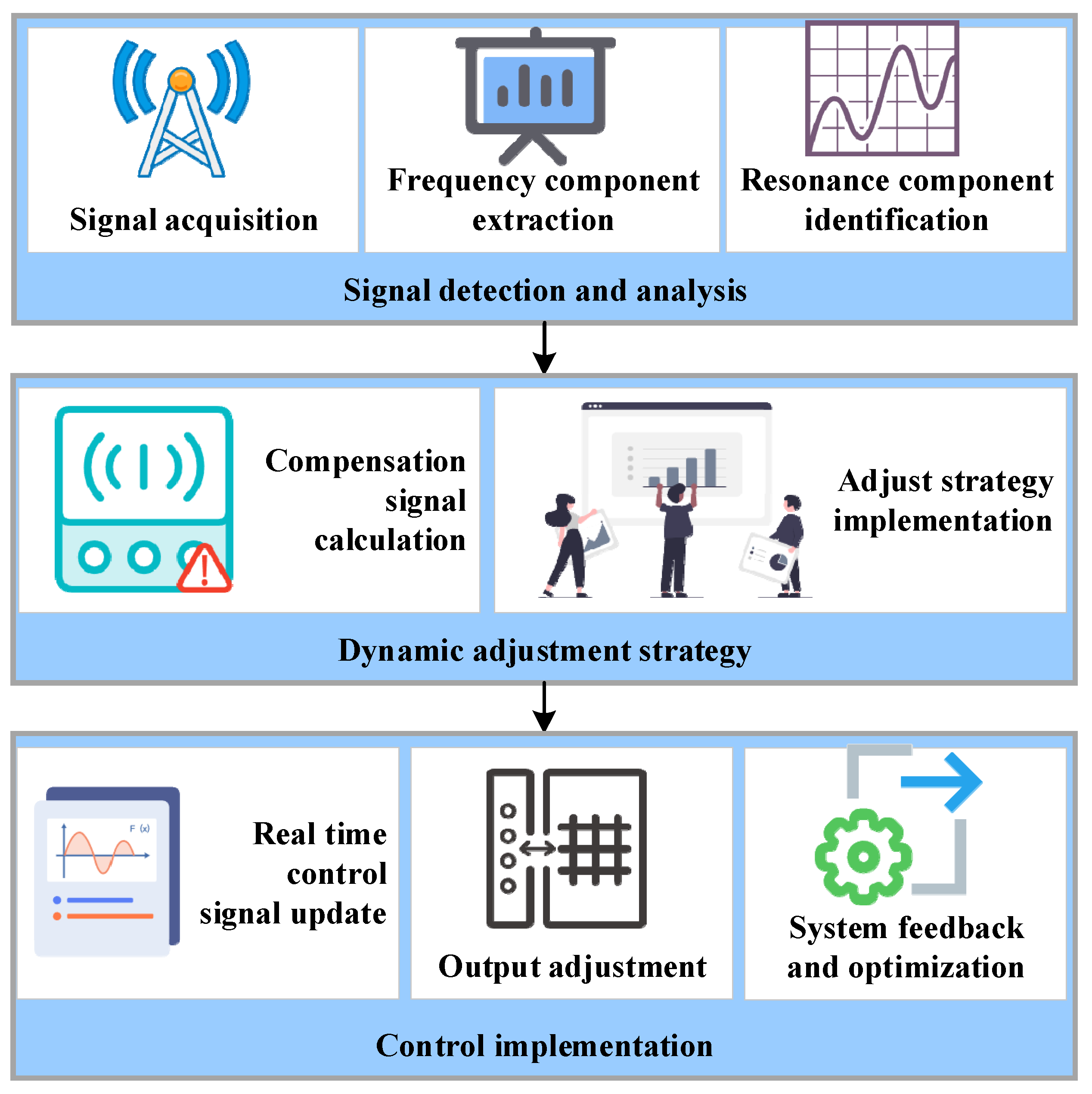
For this purpose, the following control algorithm is established. The core of this algorithm is to achieve efficient resonance frequency identification and dynamic compensation adjustment, ensuring system stability under various operating conditions. The algorithm process is illustrated in Figure 3.
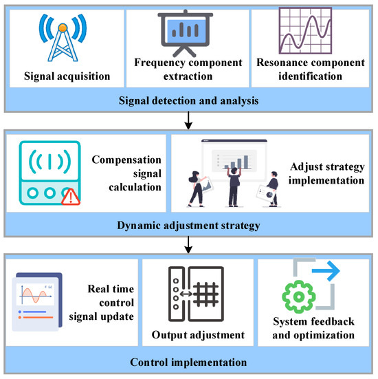
Figure 3.
Implementation process of active damping control algorithm.
In Figure 3, the process begins with signal detection and analysis. Signals collected from current and voltage sensors of the inverters, including the output current of the inverter and the grid-side voltage signal, are processed using fast Fourier transform to identify resonance frequency components present in the system. Then, by analyzing the transformed results, the main resonance frequency in the signal is identified, and the corresponding magnitude and phase information are extracted.
Next, the dynamic adjustment strategy is implemented. Based on the magnitude and phase of the resonance frequency components obtained from the signal detection and analysis step, necessary compensation signals are computed. These compensation signals have opposite phase to the resonance frequency and match the resonance magnitude to effectively counteract the resonance. The implementation of the compensation signals relies on the control capability of the inverters, achieved by modifying the pulse width modulation control signals of the inverters.
Finally, the control implementation step is executed. The computed compensation signals are converted into specific control commands, such as adjusting the modulation waveform of the inverters, and are inputted in real time into the control system of the inverters. Then, the inverters adjust their output current or voltage based on the input compensation control signals to implement resonance suppression. This step is dynamic and requires adjustments based on continuous changes in grid and load conditions. After the control implementation, the system continuously monitors the grid status and inverter outputs, and feedback information is used to optimize the control algorithm to improve response speed and compensation accuracy, ensuring long-term stable operation of the system.
3.3. Simulation Environment Construction
Considering the flexibility and widespread industrial application of simulation, MATLAB/Simulink 2022b is chosen as the primary simulation environment to support the simulation of power systems and power electronic devices. The Simulink model design revolves around core components of power systems and power electronic devices. The main circuit model meticulously describes the electrical characteristics of inverters, filters, loads, and the grid. Parameters for the inverters and filters are based on the settings in Table 1. The control logic includes implementation of active damping strategies, involving simulations of feedback loops, feedforward control, and digital signal processor algorithms. The signal processing module is responsible for signal acquisition, conversion, and processing to ensure accurate implementation of control strategies. Data logging and visualization utilize Scope modules and other visualization tools to monitor and record changes in key signals such as voltage, current, and frequency. To ensure the accuracy and practicality of the simulation environment, the parameter settings are as shown in Table 1.

Table 1.
Control Strategy Parameter Settings.
By constructing a simulation model that includes multiple inverters operating in parallel, each inverter is equipped with an independent active damping controller. By changing the number of inverters, connection methods, and grid conditions, this study explores the performance of active damping strategies in different scales and configurations to verify their applicability and robustness in actual multi machine parallel systems. Nonlinear loads are introduced in the simulation to simulate common load characteristics in real power grids. The study analyzes the impact of nonlinear loads on system stability and how active damping strategies effectively suppress resonance phenomena caused by nonlinear loads.
4. Results and Discussion
4.1. Basic Performance Evaluation
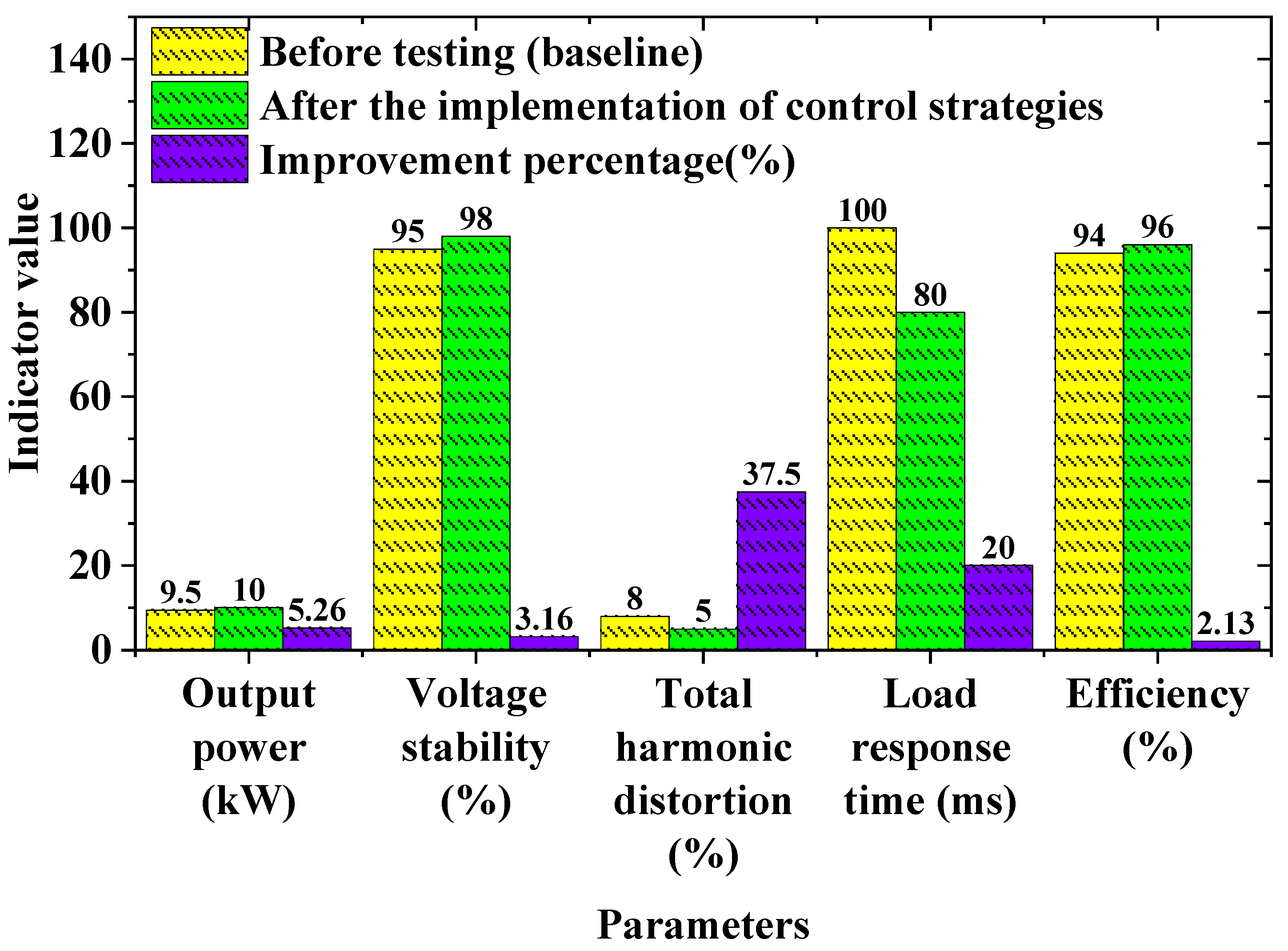
A detailed analysis of the operating performance of the inverter system under standard conditions is shown in Figure 4. Key focuses include power output, voltage stability, and the waveform quality of the current. Through a comprehensive data comparison, this study evaluates the changes in system performance before and after the implementation of the control strategy, as well as the impact of these changes on the overall system performance.

Figure 4.
Inverter output performance under basic conditions.
Figure 4 indicates that, after the implementation of the control strategy, the output power of the inverter increased from 9.5 kW to 10.0 kW. This improvement is mainly attributed to a more efficient power control and optimized energy conversion, demonstrating that the control strategy can effectively enhance the system’s power output capability. The voltage stability increases from 95% to 98%, reflecting the inverter’s enhanced ability to maintain a stable output voltage when facing grid fluctuations or load changes. By implementing the control strategy, the THD of the inverter decreases from 8% to 5%, a reduction of 37.5%. This indicates that the new strategy effectively suppresses the harmonics caused by nonlinear loads, thereby improving the quality of electrical energy. The improvement in the load response time decreases from 100 milliseconds to 80 milliseconds, demonstrating that the system responds faster to rapid load changes, which is particularly important in dynamically changing grid environments, ensuring a higher system responsiveness and reliability.
Additionally, the system efficiency increases from 94% to 96%, optimizing the energy conversion process and reducing energy losses. An improved efficiency means lower operating costs and reduced environmental impact, which is an important advancement for sustainable energy systems. The above analysis demonstrates that the implementation of the control strategy has a significant positive impact on the performance of the inverter, not only improving the basic electrical parameters but also enhancing the economic and environmental benefits of the system.
4.2. Resonance Suppression Effect
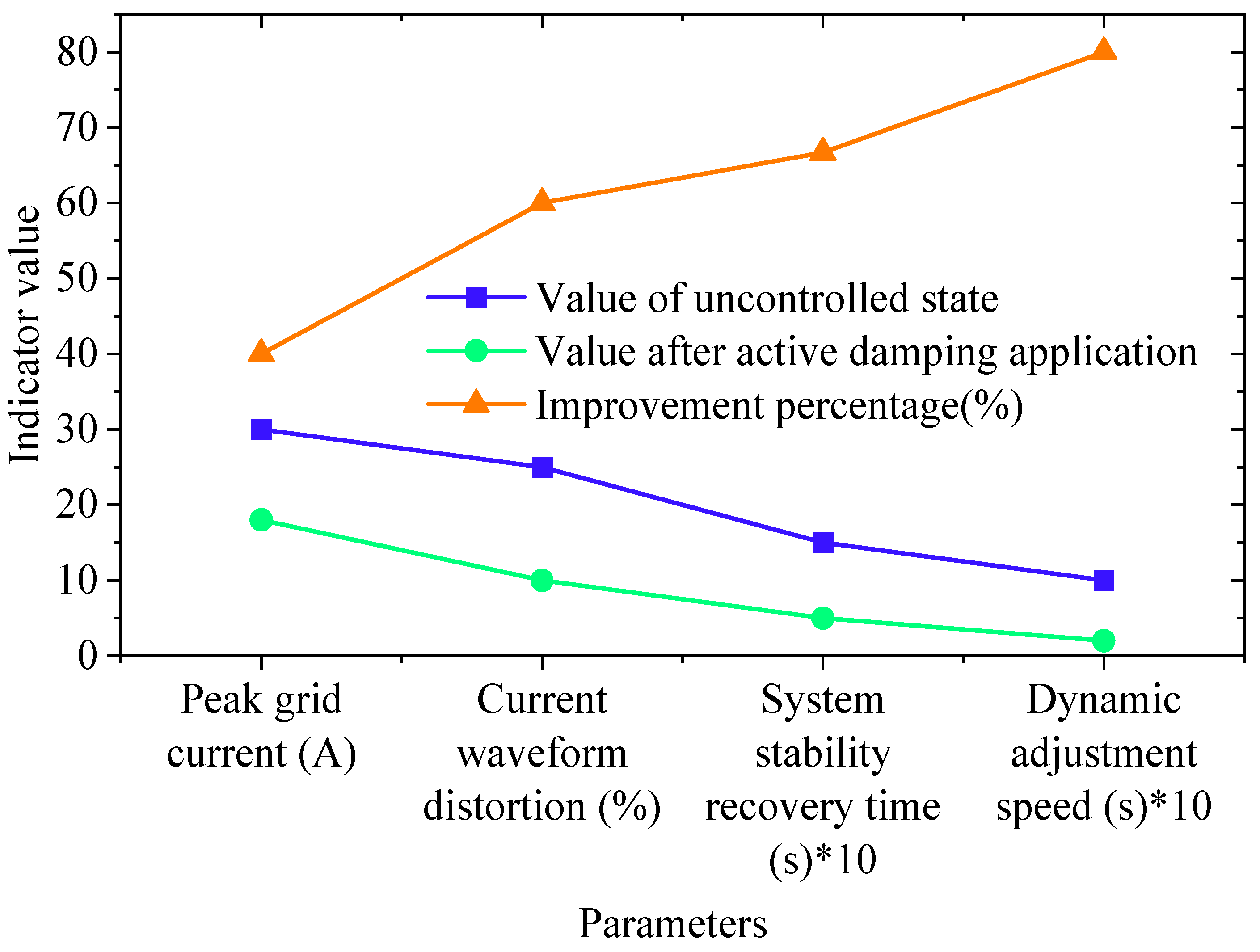
A comparison of the grid response before and after the implementation of the control strategy at the resonance frequency is shown in Figure 5.
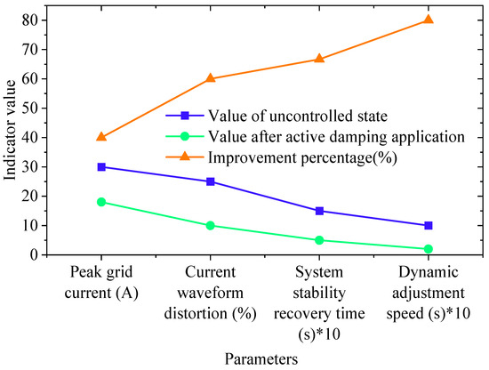
Figure 5.
Grid response at resonance frequency.
Figure 5 shows that, in the uncontrolled state, the peak value of the grid current is 30 amps, while, after applying active damping, the peak value decreases to 18 amps, improving by 40%. The data indicate that the control strategy effectively reduces the peak current, alleviating the burden on the grid and reducing the risk of overload. The distortion decreases from 25% to 10%, improving by 60%. This is particularly important because the waveform distortion directly affects the quality of the power system and the efficiency of equipment operation. By reducing distortion, the operational lifespan of equipment can be extended, and the system’s operational efficiency is higher. The resonance amplitude attenuation reaches 55%, demonstrating the effectiveness of the control strategy in reducing grid resonance. The presence of resonance can cause system instability or even damage sensitive equipment, so this result is crucial for the safety and stability of the entire grid.
The time for the system to recover from an unstable state to a stable state decreases from 1500 milliseconds to 500 milliseconds, improving by 66.7%. This means that, after a disturbance, the system can quickly return to normal operation, enhancing the system’s ability to respond to disturbances. The dynamic adjustment speed improves from 1000 milliseconds to 200 milliseconds, improving by 80%. This indicates that the control strategy can quickly respond to system changes, further enhancing the system’s adaptability and stability. These data demonstrate the significant effects of the active damping strategy in enhancing the power system performance, stability, and response speed.
4.3. System Stability Analysis
The adaptability and reliability of the active damping strategy are evaluated under different grid and load conditions, as shown in Table 2.
Table 2.
Control effectiveness under different grid conditions.
Table 2 reveals that varying environmental temperatures significantly impact the effectiveness of the control strategy under high- and low-temperature conditions. For instance, under high-temperature conditions, an increase in the grid resistance may slightly decrease the effectiveness of resonance suppression, but the power factor and stability still maintain relatively high improvements. The line length has a notable effect on the resonance suppression effectiveness, as longer lines may exhibit more effective resonance suppression due to their larger line inductance and capacitance effects. The load type is also a crucial factor; dynamic loads demonstrate the effectiveness of the control strategy more than static loads, possibly because dynamic loads induce greater fluctuations in the grid, requiring more control inputs to stabilize the system.
5. Conclusions
This study designs and implements an effective active damping strategy aimed at improving the performance and stability of grid connected inverter systems. Through detailed simulation verification, this control strategy not only optimizes the output characteristics of the inverter, but also significantly suppresses resonance problems in the power grid, enhancing the overall stability of the system. The developed control algorithm effectively counteracts the resonant frequency of the power grid by dynamically adjusting the inverter output, reduces total harmonic distortion in the system, and improves the stability of voltage and current. Simulation of inverter performance under different conditions shows that this control strategy maintains efficiency and stability under changing grid conditions, enhancing its practicality and reliability. Despite the positive outcomes of this study, some limitations remain. Therefore, future plans involve continuing to refine control algorithms to adapt to a wider range of grid conditions and more complex disturbances, especially in applications involving nonlinear loads and large-scale distributed generation scenarios.
Author Contributions
Conceptualization, T.H. and Y.J.; Methodology, T.H.; Software, T.H.; Validation, Y.J.; Resources, T.H. and Z.C.; Data curation, T.H. and Z.C.; Writing—original draft, T.H. and Z.C.; Writing—review & editing, T.H. and Y.J.; Project administration, Y.J. All authors have read and agreed to the published version of the manuscript.
Funding
This research received no external funding.
Data Availability Statement
The raw data supporting the conclusions of this article will be made available by the authors on request.
Conflicts of Interest
The authors declare no conflict of interest.
References
- Salem, M.; Richelli, A.; Yahya, K.; Hamidi, M.N.; Ang, T.Z.; Alhamrouni, I. A comprehensive review on multilevel inverters for grid-tied system applications. Energies 2022, 15, 6315. [Google Scholar] [CrossRef]
- Easley, M.; Shadmand, M.B.; Abu-Rub, H. Hierarchical model predictive control of grid-connected cascaded multilevel inverter. IEEE J. Emerg. Sel. Top. Power Electron. 2020, 9, 3137–3149. [Google Scholar] [CrossRef]
- Barkat, F.; Cheknane, A.; Guerrero, J.M.; Lashab, A.; Istrate, M.; Viorel Banu, I. Hybrid islanding detection technique for single-phase grid-connected photovoltaic multi-inverter systems. IET Renew. Power Gener. 2020, 14, 3864–3880. [Google Scholar] [CrossRef]
- He, S.; Zhou, D.; Wang, X.; Blaabjerg, F. Line voltage sensorless control of grid-connected inverters using multisampling. IEEE Trans. Power Electron. 2021, 37, 4792–4803. [Google Scholar] [CrossRef]
- Barzegarkhoo, R.; Lee, S.S.; Khan, S.A.; Siwakoti, Y.P.; Lu, D.D.C. A novel generalized common-ground switched-capacitor multilevel inverter suitable for transformerless grid-connected applications. IEEE Trans. Power Electron. 2021, 36, 10293–10306. [Google Scholar] [CrossRef]
- Zhang, M.; Wang, J.; Zhang, S.; Gao, L.; Guo, X.; Chen, L.; Xu, Y. Harmonic Resonance Analysis and Impedance Remodeling Method of Multi-Inverter Grid-Connected System. Electronics 2023, 12, 3684. [Google Scholar] [CrossRef]
- Yang, W.; Wang, D.; Wang, X.; Li, X.; Zhang, P. Resonance Analysis of Medium Voltage Multi-Microgrids Considering the Interaction of Controllable Series Compensator and Grid-Connected Inverters. J. Electr. Eng. Technol. 2024, 19, 1005–1022. [Google Scholar] [CrossRef]
- Liu, J.; Sun, X.; Chen, Z.; Chi, Y.; Song, W.; Zhu, Q.; Wheeler, P. A Hybrid Multiresonances Suppression Method for Nonsynchronous LCL-Type Grid-Connected Inverter Clusters Under Weak Grid. IEEE Trans. Power Electron. 2024, 39, 5386–5399. [Google Scholar] [CrossRef]
- Li, Q.; Sun, P.; Dong, G.; Chen, Y. Resonance coupling analysis of multiple differently parameterized grid-connected inverters in new energy generation. Int. J. Electr. Power Energy Syst. 2024, 156, 109743. [Google Scholar] [CrossRef]
- Chen, L.; Xu, Y.; Tao, S.; Wang, T.; Sun, S. Multi-inverter resonance modal analysis based on decomposed conductance model. Electronics 2023, 12, 1251. [Google Scholar] [CrossRef]
- Zheng, F.; Wu, G.; Lin, X.; Zheng, S.; Wu, X.; Lin, Y.; Deng, C. Research on control strategy for improving stability of multi-inverter parallel system under weak grid condition. Int. J. Electr. Power Energy Syst. 2023, 153, 109121. [Google Scholar] [CrossRef]
- Wang, X.; Rong, X.; Huang, P.; Zhao, X. Stability analysis and resonance suppression of multi-inverter parallel operation. Electr. Power Syst. Res. 2024, 226, 109907. [Google Scholar] [CrossRef]
- Samanes, J.; Urtasun, A.; Gubia, E.; Petri, A. Robust multisampled capacitor voltage active damping for grid-connected power converters. Int. J. Electr. Power Energy Syst. 2019, 105, 741–752. [Google Scholar] [CrossRef]
- Khan, A.; Gastli, A.; Ben-Brahim, L. Modeling and control for new LLCL filter based grid-tied PV inverters with active power decoupling and active resonance damping capabilities. Electr. Power Syst. Res. 2018, 155, 307–319. [Google Scholar] [CrossRef]
- Yuan, C.; Shi, D.; Hu, Q.; Liao, Y.; Yu, J.; Zhou, P. Active damping resonance suppression and optimization of photovoltaic cluster grid connected system. J. Electr. Eng. Technol. 2021, 16, 2509–2521. [Google Scholar] [CrossRef]
- Guo, Y.; Lu, X.; Chen, L.; Zheng, T.; Wang, J.; Mei, S. Functional-rotation-based active dampers in AC microgrids with multiple parallel interface inverters. IEEE Trans. Ind. Appl. 2018, 54, 5206–5215. [Google Scholar] [CrossRef]
- Xu, X.; Yao, W.; Xie, G. A Damping Control Strategy to Improve the Stability of Multi-Parallel Grid-Connected PCSs. Energies 2023, 16, 4633. [Google Scholar] [CrossRef]
- Zhang, X.; Yu, C.; Liu, F.; Li, F.; Xu, H. Overview on resonance characteristics and resonance suppression strategy of multi-parallel photovoltaic inverters. Chin. J. Electr. Eng. 2016, 2, 40–51. [Google Scholar]
- Li, Y.; Zhang, J.; Hao, Z.; Tian, P. Improved PR control strategy for an LCL three-phase grid-connected inverter based on active damping. Appl. Sci. 2021, 11, 3170. [Google Scholar] [CrossRef]
- Petric, I.Z.; Mattavelli, P.; Buso, S. Passivation of grid-following VSCs: A comparison between active damping and multi-sampled PWM. IEEE Trans. Power Electron. 2022, 37, 13205–13216. [Google Scholar] [CrossRef]
- Jurkov, A.S.; Radomski, A.; Perreault, D.J. Tunable matching networks based on phase-switched impedance modulation. IEEE Trans. Power Electron. 2020, 35, 10150–10167. [Google Scholar] [CrossRef]
- Jiang, S.; Konstantinou, G. Generalized impedance model and interaction analysis for multiple grid-forming and grid-following converters. Electr. Power Syst. Res. 2023, 214, 108912. [Google Scholar] [CrossRef]
- Büyük, M.; Tan, A.; Tümay, M. Resonance suppression of LCL filter for shunt active power filter via active damper. Int. J. Electr. Power Energy Syst. 2022, 134, 107389. [Google Scholar] [CrossRef]
- Yang, S.; Liu, K.; Qin, L.; Zhu, S.; Xu, B.; Wang, Q. A broadband active damping method for high-frequency resonance suppression in MMC-HVDC system. Int. J. Electr. Power Energy Syst. 2023, 146, 108791. [Google Scholar] [CrossRef]
- Babu, N.; Guerrero, J.M.; Siano, P.; Peesapati, R.; Panda, G. A novel modified control scheme in grid-tied photovoltaic system for power quality enhancement. IEEE Trans. Ind. Electron. 2020, 68, 11100–11110. [Google Scholar]
- Wang, S.; Li, Y.; Zhang, M.; Peng, Y.; Tian, Y.; Lin, G.; Chang, F. Harmonic resonance suppression with inductive power filtering method: Case study of large-scale photovoltaic plant in China. IEEE Trans. Power Electron. 2023, 38, 6444–6454. [Google Scholar] [CrossRef]
- Meraj, S.T.; Yahaya, N.Z.; Hasan, K.; Lipu, M.H.; Elavarasan, R.M.; Hussain, A.; Hannan, M.A.; Muttaqi, K.M. A filter less improved control scheme for active/reactive energy management in fuel cell integrated grid system with harmonic reduction ability. Appl. Energy 2022, 312, 118784. [Google Scholar] [CrossRef]
- Li, Z.; Wang, M.; Fan, G.; Zeng, X.; Yan, Y.; Ma, F. Effects of rolling motion on flow and heat transfer characteristics in a tube bundle channel. Appl. Therm. Eng. 2023, 220, 119696. [Google Scholar] [CrossRef]
- Xue, R.; Li, G.; Tong, H.; Chen, Y. Adaptive active damping method of grid-connected inverter based on model predictive control in weak grid. J. Power Electron. 2022, 22, 1100–1111. [Google Scholar] [CrossRef]
- Cai, Y.; He, Y.; Zhou, H.; Liu, J. Active-damping disturbance-rejection control strategy of LCL grid-connected inverter based on inverter-side-current feedback. IEEE J. Emerg. Sel. Top. Power Electron. 2020, 9, 7183–7198. [Google Scholar] [CrossRef]
- Zhang, H.; Wang, Y.; Zhu, X.; Xu, Y.; Tao, S. DC Active Damper Control Strategy Based on Resonance Suppression Effectiveness Evaluation Method. Energies 2024, 17, 480. [Google Scholar] [CrossRef]
- Dash, D.K.; Sadhu, P.K. A Review on the Use of Active Power Filter for Grid-Connected Renewable Energy Conversion Systems. Processes 2023, 11, 1467. [Google Scholar] [CrossRef]
- Yusuf, S.D.; Loko, A.Z.; Abdullahi, J.; Abdulhamid, A.A. Performance Analysis of Three-Phase Shunt Active Power Filter for Harmonic Mitigation. Asian J. Res. Rev. Phys. 2022, 6, 7–24. [Google Scholar] [CrossRef]

Disclaimer/Publisher’s Note: The statements, opinions and data contained in all publications are solely those of the individual author(s) and contributor(s) and not of MDPI and/or the editor(s). MDPI and/or the editor(s) disclaim responsibility for any injury to people or property resulting from any ideas, methods, instructions or products referred to in the content. |
© 2024 by the authors. Licensee MDPI, Basel, Switzerland. This article is an open access article distributed under the terms and conditions of the Creative Commons Attribution (CC BY) license (https://creativecommons.org/licenses/by/4.0/).