
Study of the Thermal Performance of Solar Air Collectors with and without Perforated Baffles

 , and
, and 
Abstract
1. Introduction
Motivation and Objective of the Study
2. Materials and Methods
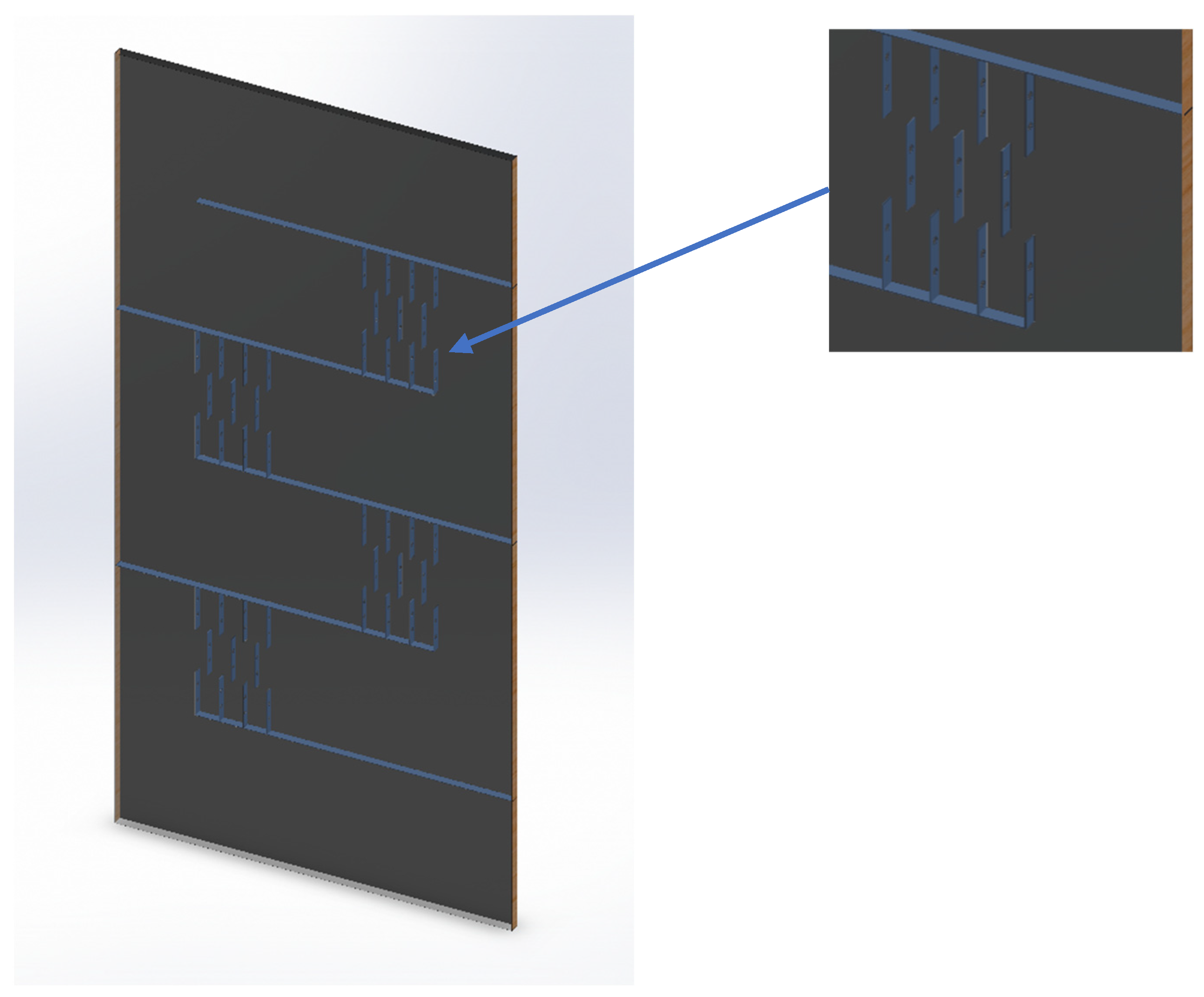
2.1. Geometry
- The first case: solar collector without baffles “Smooth“.
- The second case: solar collector with transverse and longitudinal baffles “LT”.
- The third case: a solar collector with a single hole in the middle of the transverse baffles, 10 mm of diameter “LTH 1”.
- The fourth case: a solar collector with a single hole in the middle of the transverse baffles 15 mm of diameter “LTH 1”.
- The fifth case: a solar collector with two holes in the transverse baffles, 10 mm in diameter “LTH 2”.
- The sixth case: a solar collector with two holes in the transverse baffles 15 mm in diameter “LTH 2”.
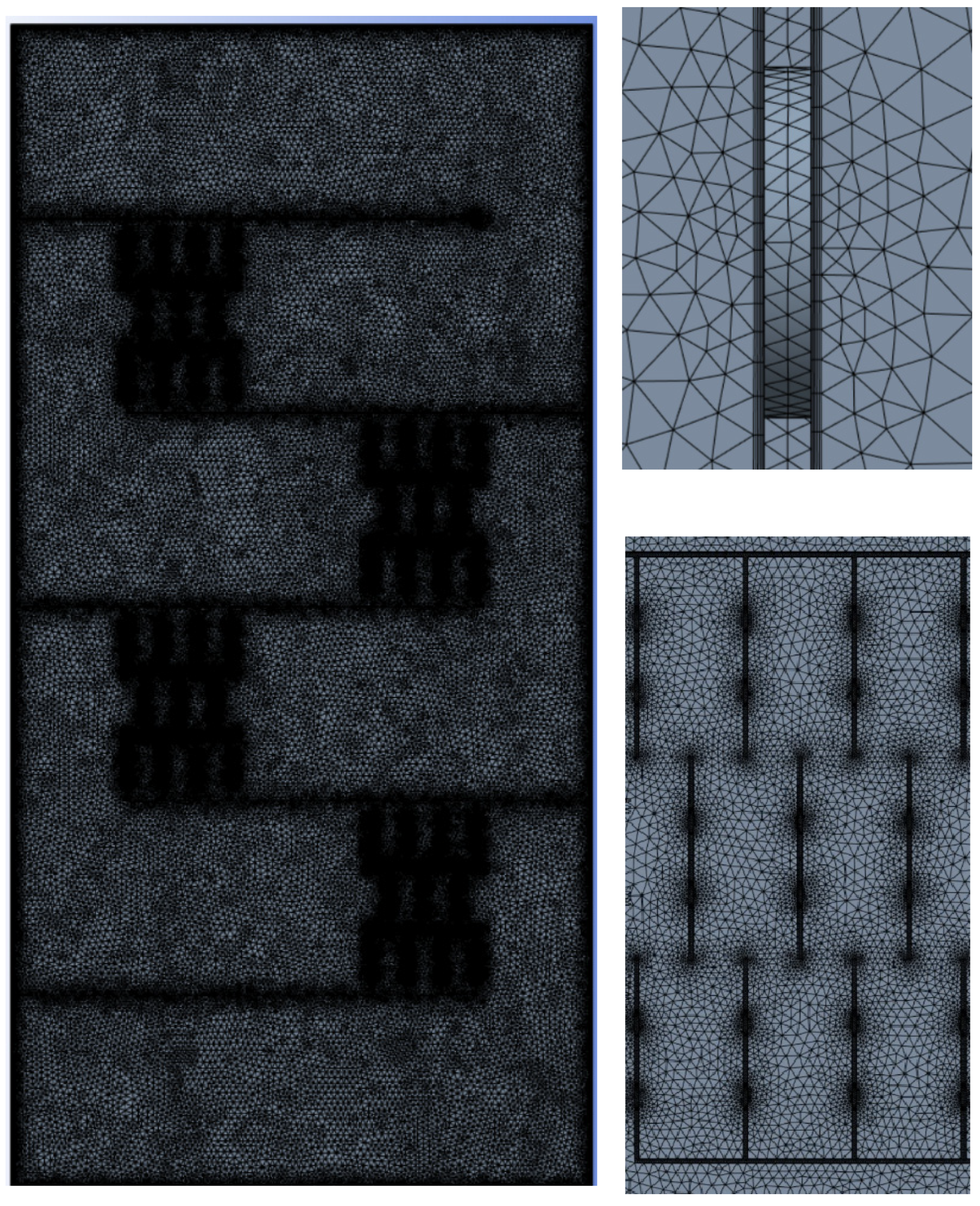
2.2. Grid Mesh
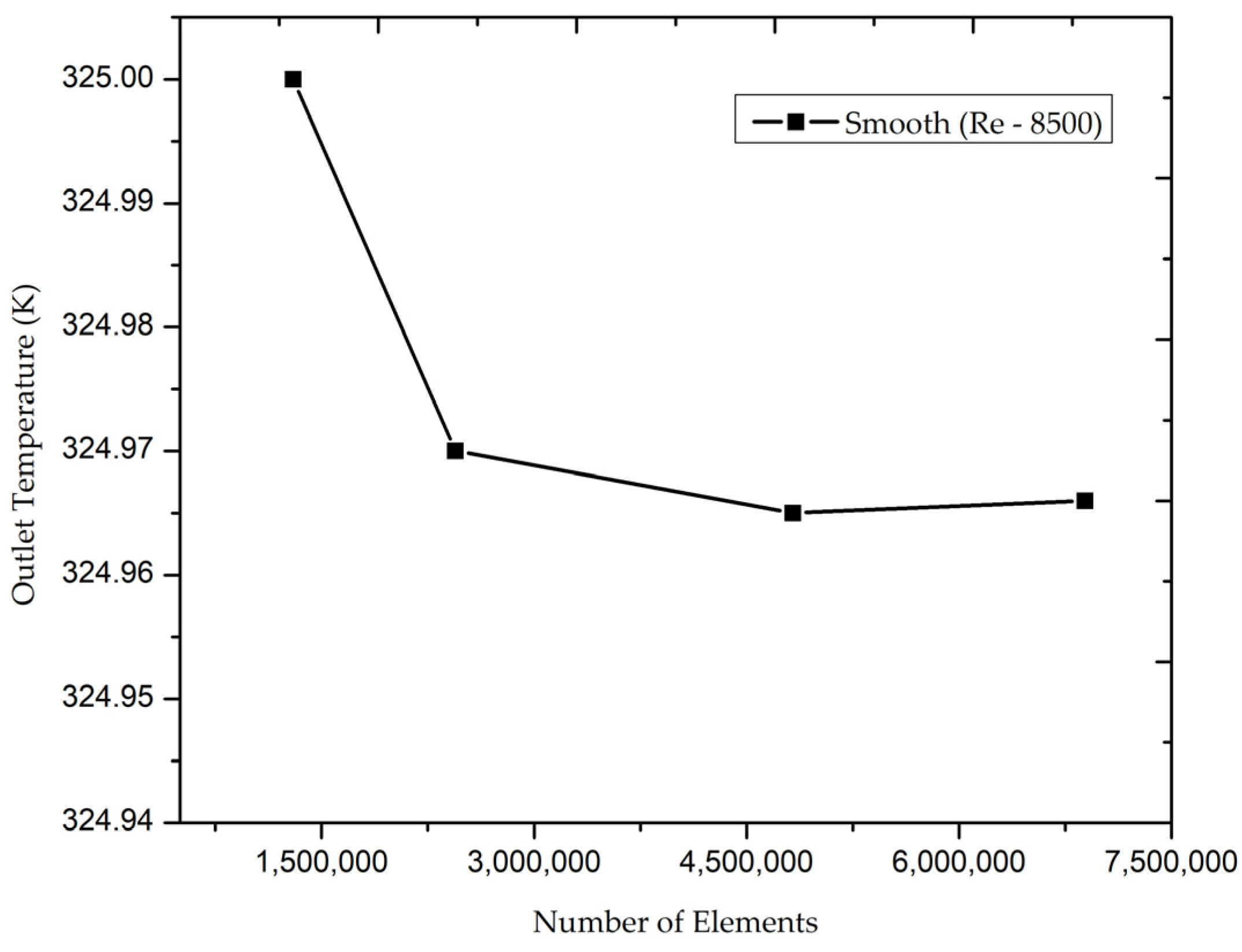
2.3. Grid Independence Study
2.4. Mathematical Modeling and Solution Technique
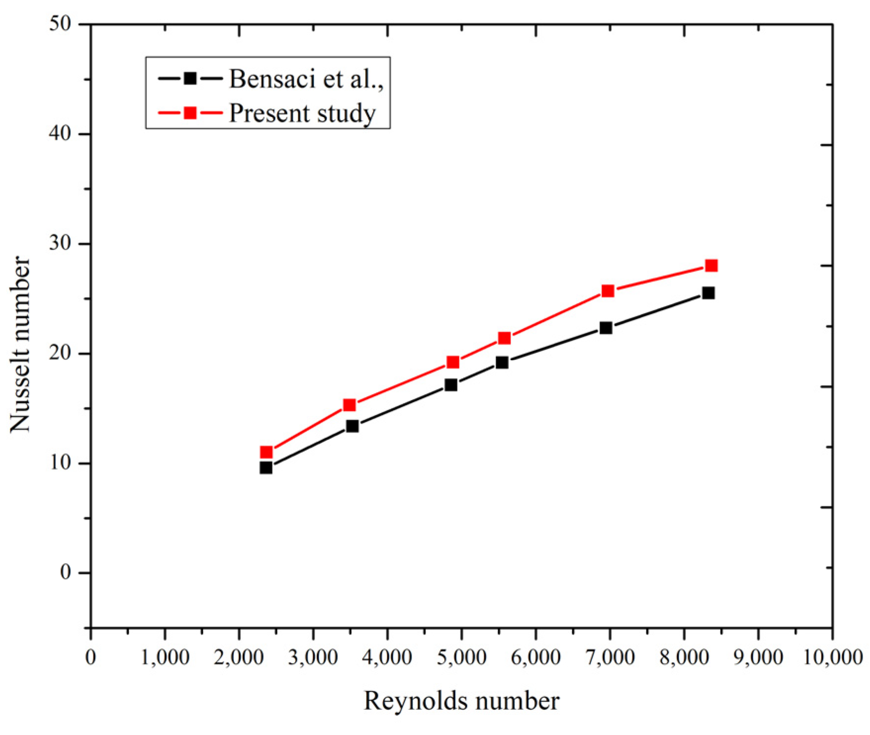
2.5. Validation
3. The Boundary Conditions
4. Results and Discuss
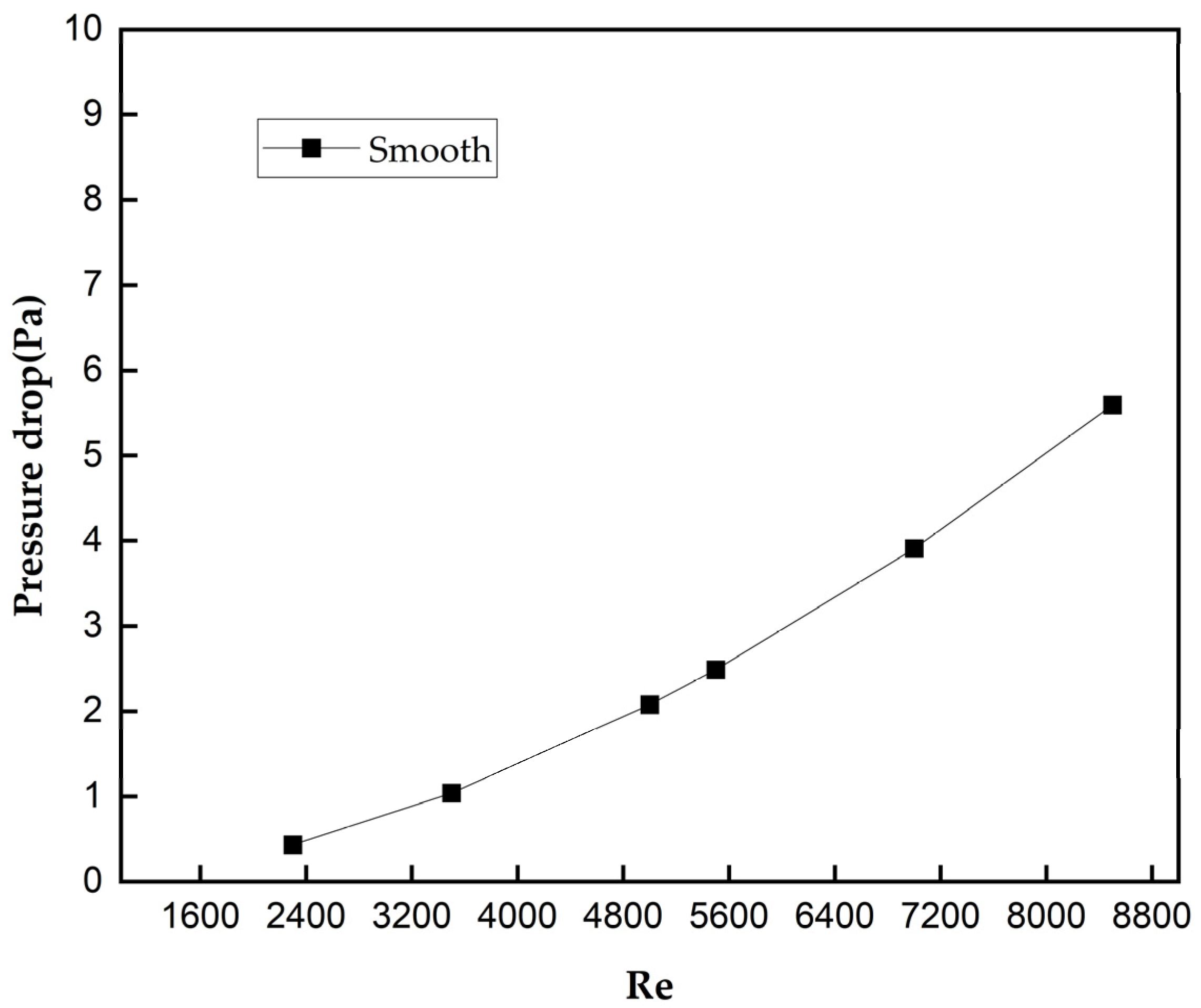
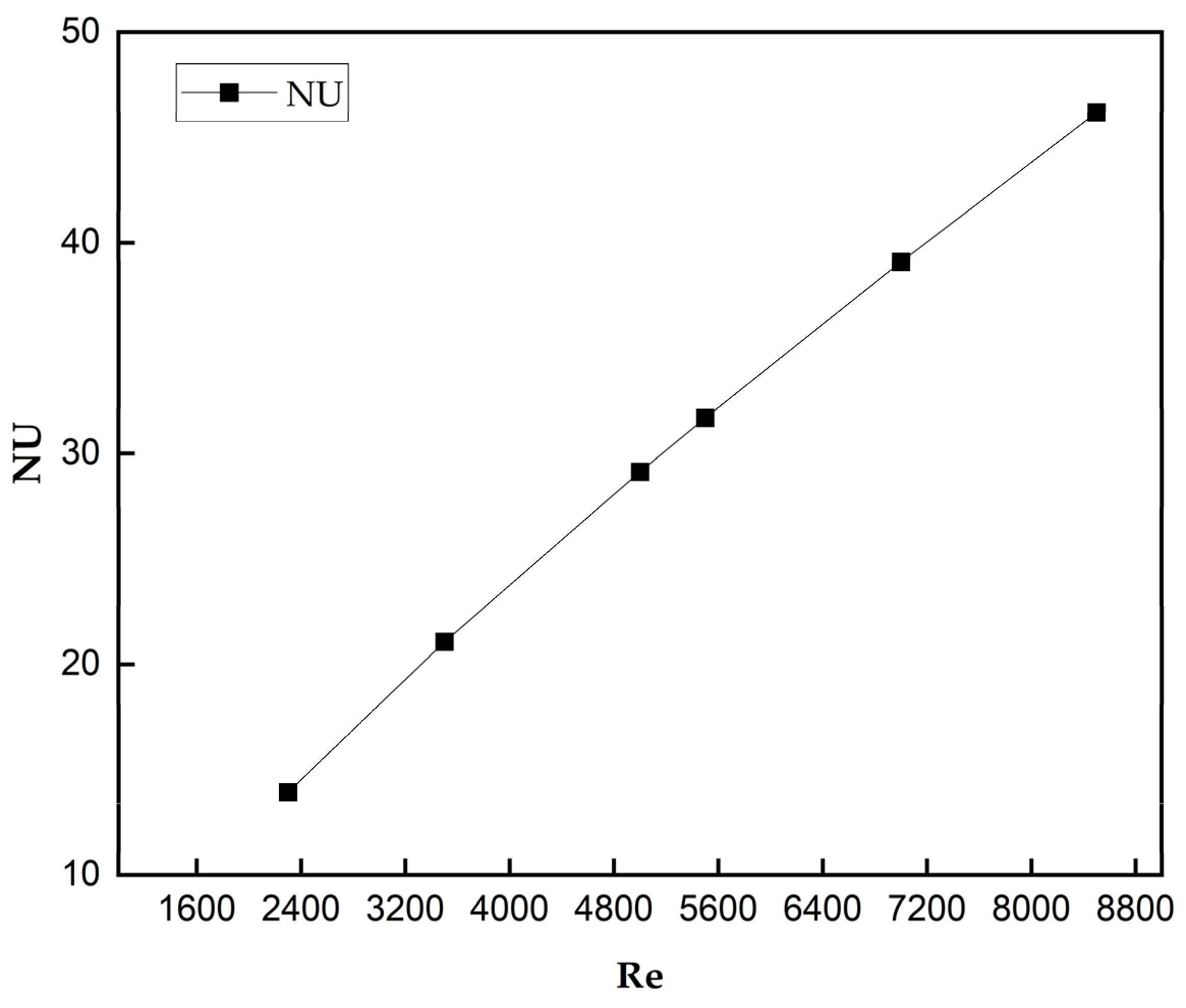
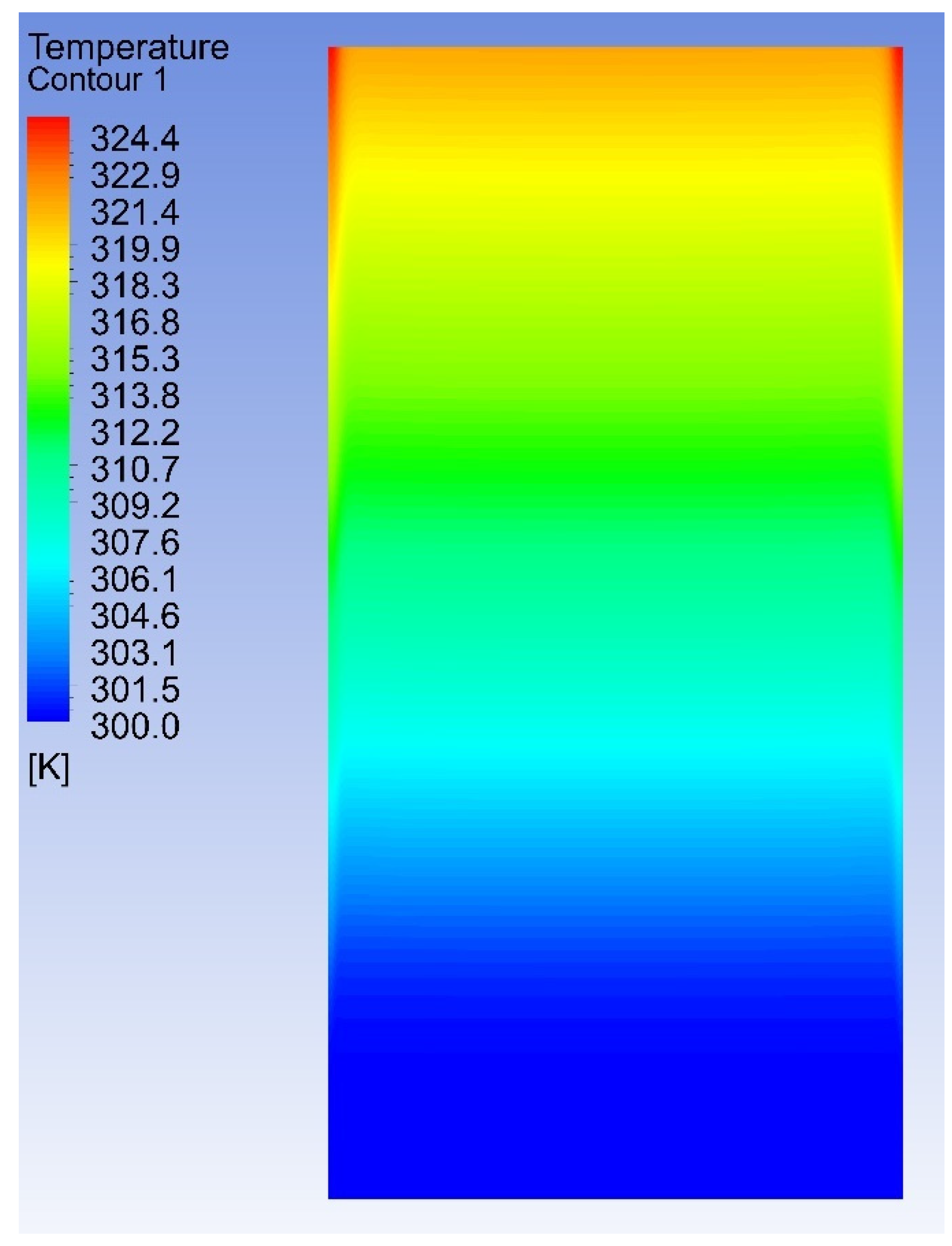
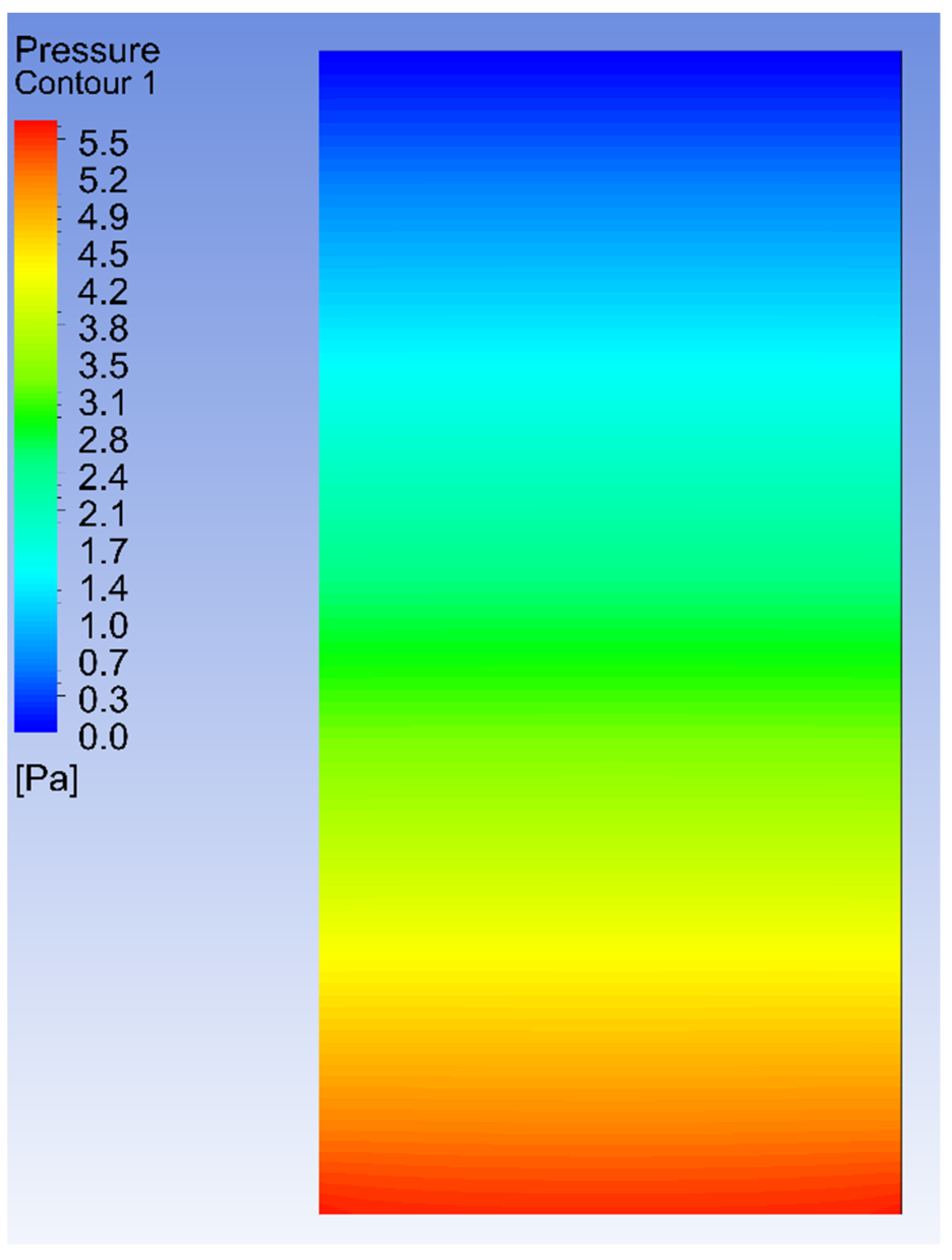
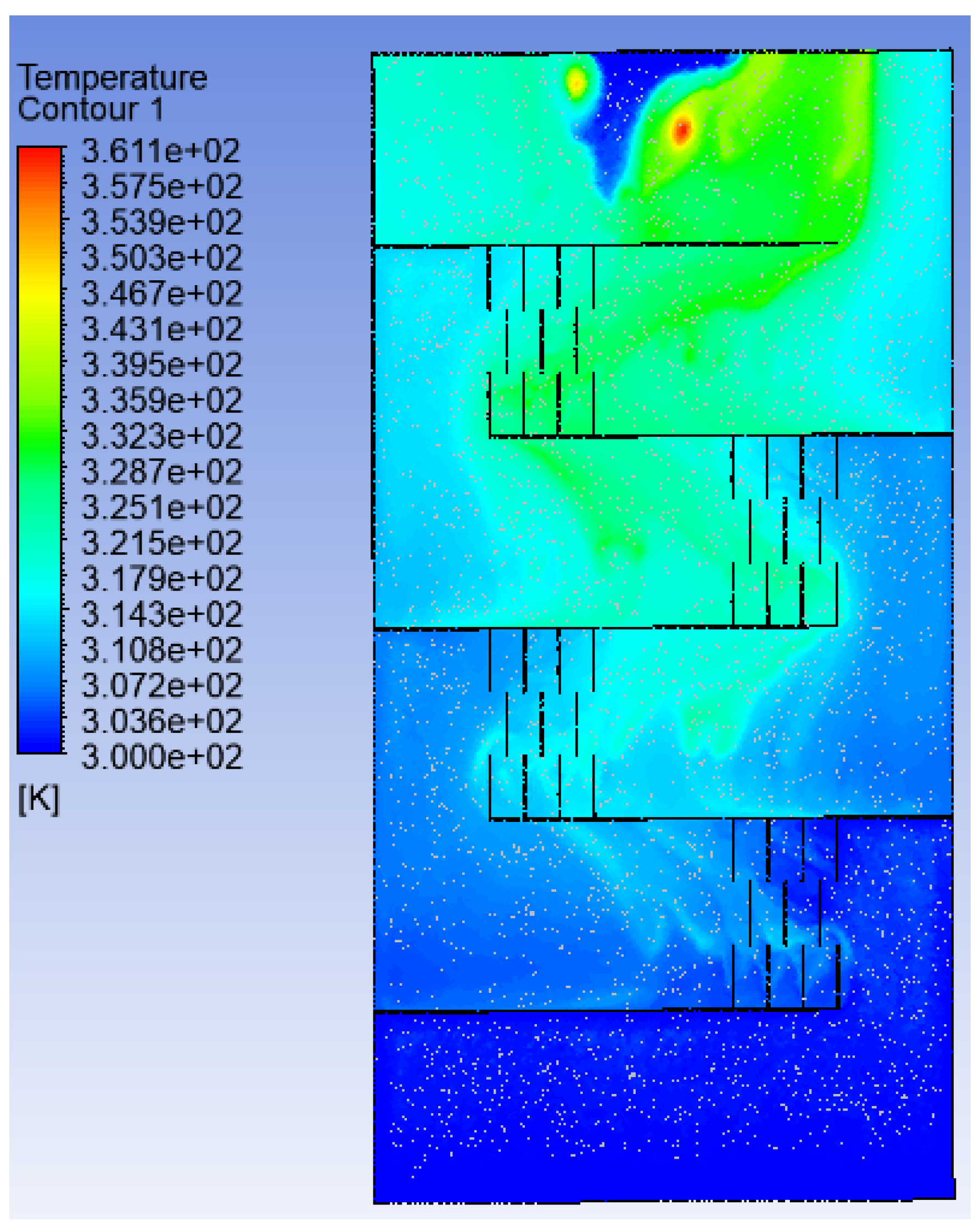
4.1. Smooth Case
4.2. Comparison of Longitudinal and Transverse Baffles with and without Perforation
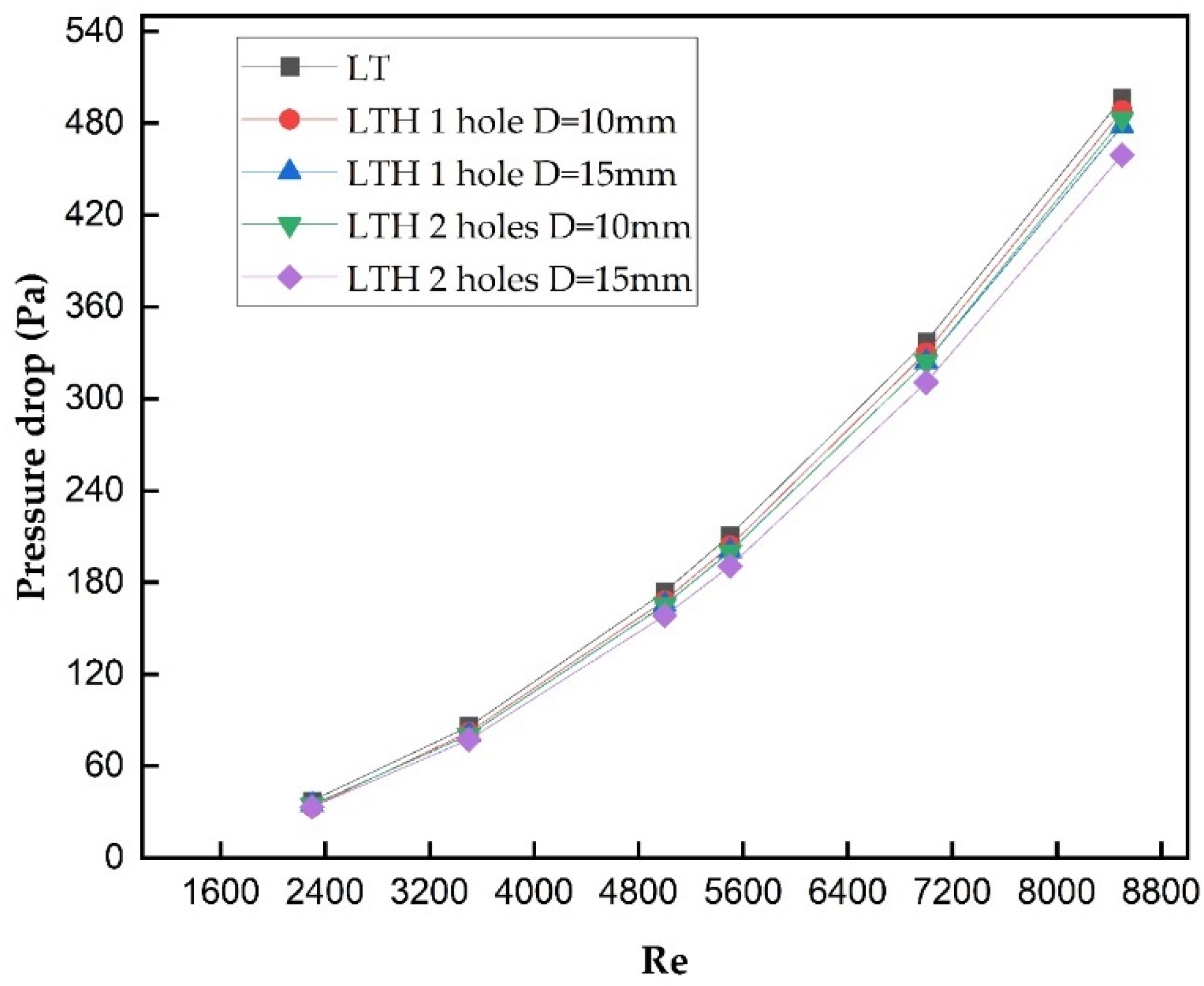
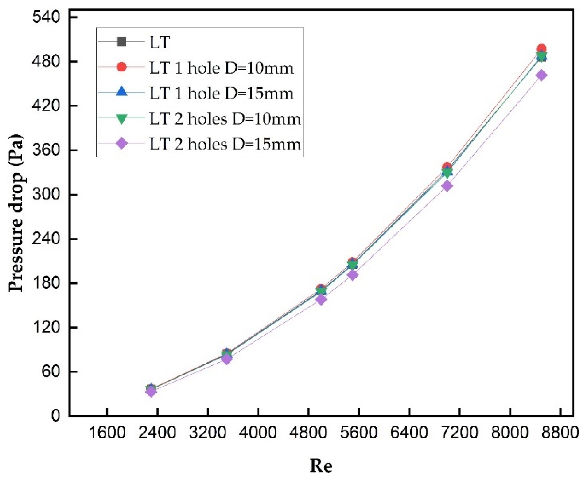
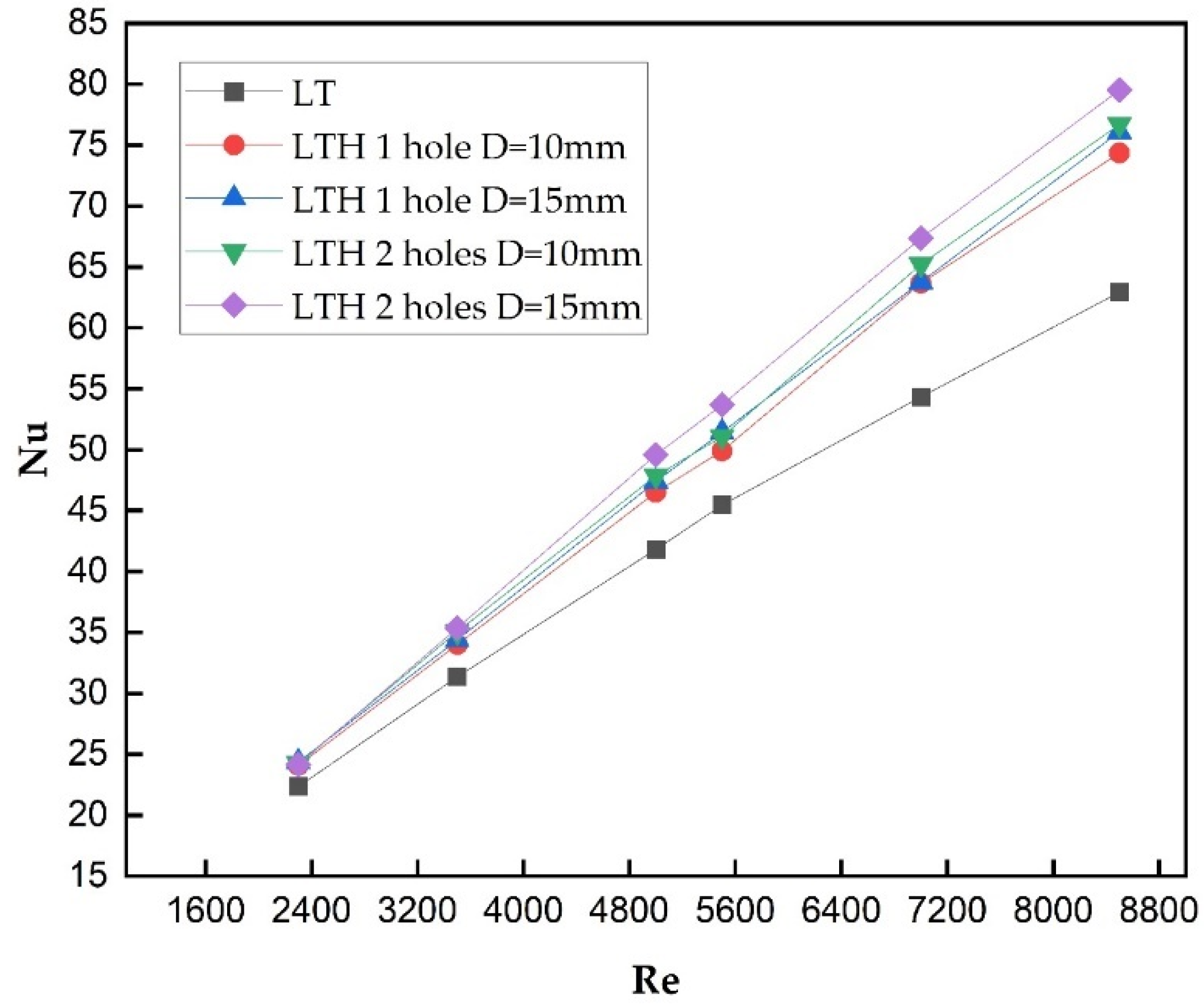
Assessment of the Nusselt Number and Pressure Drop
5. Conclusions
- The study revealed that utilizing longitudinal and transverse baffles led to improved heat transfer characteristics compared to a smooth surface. This improvement was manifested by an increase in the Nusselt number. However, it is important to note that a significant increase in pressure drop accompanied this enhanced performance. The influence of baffle thickness on the improvement in Nusselt number or the increase in pressure drop was found to be negligible;
- On comparison of baffles with and without perforation, results clearly predicted that perforated baffles with LTH 2 holes with a diameter of 15 mm provided better heat transfer characteristics and a better estimated maximum Nu and optimal pressure drop than LTH 1 holes of diameters 10 mm and 15 mm and LT without perforation for all Re, respectively. Also, variation in the thickness of baffles has no significant improvement in terms of the Nu and pressure drop of all the models considered. Even though thickness has no impact on the thermal performance of solar air collectors, it will be a deciding factor in terms of the selection of thickness of baffles.
Author Contributions
Funding
Data Availability Statement
Conflicts of Interest
Nomenclature
| Specific heat capacity (J·kg−1·K−1) | |
| H | Heat transfer coefficient (W·m−2·K−1) |
| K | Turbulence kinetic energy (m2·s−2) |
| Nu | Nusselt number |
| Q | Absorbed heat flux (W·m−2) |
| Re | Reynolds number |
| T | Temperature (K) |
| V | Velocity (m/s) |
| P | Pressure (Pa) |
| ṁ | Air mass flow rate per meter (kg/m·s) |
| The turbulent viscosity. | |
| Absorber plate surface area (m2) | |
| Fluid density (kg·m−3) |
Abbreviations
| SAH | Solar air heater. |
| SAC | Solar air collector. |
| RHMA | Reference hot-mix asphalt. |
| C-HMA | Conductive hot-mix asphalt. |
| CSCs | Concentrated solar collectors. |
| FPSACs | Flat-plate solar air collectors. |
| TSAC | Triangular solar air collector. |
| PCM | Phase change material. |
| DSAC | Double flow solar air collector. |
| NFAD | Nano-enhanced flexible aluminum air duct. |
| FESAC | Front entrance solar air collector. |
| SESAC | Side entrance solar air collector. |
| CPC | Compound parabolic concentrator. |
| WCSAC | Wavy corrugated solar air collector. |
| IB-ETC-SAH | Inserting a baffle inside the ETC-SAH. |
| PPI | Pores per inch. |
References
- Labed, A.; Moummi, N.; Aouès, K.; Zellouf, M.; Moummi, A. Etude Théorique et Expérimentale Des Performances d’un Capteur Solaire Plan à Air Muni d’une Nouvelle Forme de Rugosité Artificielle. J. Renew. Energ. 2009, 12, 551. [Google Scholar] [CrossRef]
- Menasria, F.; Moummi, E.; Moummi, N.; Zedayria, M.; Guestal, M. Modélisation Des Échanges Convectifs Dans Le Conduit Utile d’un Capteur Solaire Plan à Air Muni de Rugosités Artificielles de Formes Rectangulaires. J. Renew. Energ. 2023, 14, 369–379. [Google Scholar] [CrossRef]
- Fakoor Pakdaman, M.; Lashkari, A.; Basirat Tabrizi, H.; Hosseini, R. Performance Evaluation of a Natural-Convection Solar Air-Heater with a Rectangular-Finned Absorber Plate. Energy Convers. Manag. 2011, 52, 1215–1225. [Google Scholar] [CrossRef]
- Bensaci, C.E.; Moummi, A.; Sanchez de la Flor, F.J.; Rodriguez Jara, E.A.; Rincon-Casado, A.; Ruiz-Pardo, A. Numerical and Experimental Study of the Heat Transfer and Hydraulic Performance of Solar Air Heaters with Different Baffle Positions. Renew. Energy 2020, 155, 1231–1244. [Google Scholar] [CrossRef]
- Sharma, S.; Kumar Das, R.; Kulkarni, K. Sustainability Analysis of Solar Air Heater Roughned with Baffles Based on Exergy Efficiency. Mater. Today Proc. 2022, 69, 75–81. [Google Scholar] [CrossRef]
- Rani, P.; Tripathy, P.P. Experimental Investigation on Heat Transfer Performance of Solar Collector with Baffles and Semicircular Loops Fins under Varied Air Mass Flow Rates. Int. J. Therm. Sci. 2022, 178, 107597. [Google Scholar] [CrossRef]
- Mohammadi, K.; Sabzpooshani, M. Appraising the Performance of a Baffled Solar Air Heater with External Recycle. Energy Convers. Manag. 2014, 88, 239–250. [Google Scholar] [CrossRef]
- Rani, P.; Tripathy, P.P. Thermal Characteristics of a Flat Plate Solar Collector: Influence of Air Mass Flow Rate and Correlation Analysis among Process Parameters. Sol. Energy 2020, 211, 464–477. [Google Scholar] [CrossRef]
- Biswas, R.; Tripathy, P.P. Finite Element Based Computational Analysis to Study the Effects of Baffle and Fin on the Performance Assessment of Solar Collector. Therm. Sci. Eng. Prog. 2024, 49, 102431. [Google Scholar] [CrossRef]
- Promvonge, P.; Skullong, S. Thermal Characteristics in Solar Air Duct with V-Shaped Flapped-Baffles and Chamfered-Grooves. Int. J. Heat Mass Transf. 2021, 172, 121220. [Google Scholar] [CrossRef]
- Sai Kandukuri, K.; Kishor Sharma, P.; Kumar Arun, R. A Comparative Assessment of Distributive Mode Active Solar Dryers: Flat Plate Collector vs Evacuated Tube Collector with Thermal Energy Storage and Perforated Baffled Trays. Sol. Energy 2024, 271, 112421. [Google Scholar] [CrossRef]
- Hu, J.; Liu, K.; Ma, L.; Sun, X. Parameter Optimization of Solar Air Collectors with Holes on Baffle and Analysis of Flow and Heat Transfer Characteristics. Sol. Energy 2018, 174, 878–887. [Google Scholar] [CrossRef]
- Khanlari, A.; Aytaç, İ.; Tuncer, A.D.; Variyenli, H.İ.; Şahin, H.N. Improving the Performance of a PCM Integrated Solar Air Collector by Adding Porous Fins over the Bottom Side of the Absorber: A Transient CFD Study. J. Energy Storage 2024, 90, 111847. [Google Scholar] [CrossRef]
- Abbas, F.A.; Alhamdo, M.H. Experimental and Numerical Analysis of an Asphalt Solar Collector with a Conductive Asphalt Mixture. Energy Rep. 2024, 11, 327–341. [Google Scholar] [CrossRef]
- Zhang, J.; Zhu, T. Systematic Review of Solar Air Collector Technologies: Performance Evaluation, Structure Design and Application Analysis. Sustain. Energy Technol. Assess. 2022, 54, 102885. [Google Scholar] [CrossRef]
- Jiang, Y.; Zhang, H.; Zhao, R.; Liu, Z.; Wang, Y.; You, S.; Wu, Z.; Wei, S. Thermal and Optical Performance Analysis of Triangular Solar Air Collectors and Regional Applicability in China. Sol. Energy 2023, 249, 288–300. [Google Scholar] [CrossRef]
- Rajaseenivasan, T.; Srinivasan, S.; Srithar, K. Comprehensive Study on Solar Air Heater with Circular and V-Type Turbulators Attached on Absorber Plate. Energy 2015, 88, 863–873. [Google Scholar] [CrossRef]
- Patel, S.S.; Lanjewar, A. Experimental Analysis for Augmentation of Heat Transfer in Multiple Discrete V-Patterns Combined with Staggered Ribs Solar Air Heater. Renew. Energy Focus 2018, 25, 31–39. [Google Scholar] [CrossRef]
- Öztürk, M.; Çiftçi, E. Upgrading the Performance of a Solar Air Collector with Flexible Aluminum Air Ducts and Graphene Nanoplatelet-Enhanced Absorber Coating. Therm. Sci. Eng. Prog. 2023, 40, 101760. [Google Scholar] [CrossRef]
- Nowzaria, R.; Aldabbagh, L.B.Y.; Mirzaei, N. Experimental Study on Double Pass Solar Air Heater with Mesh Layers as Absorber Plate. Int. J. Electron. Mech. Mechatron. Eng. 2011, 3, 673–682. [Google Scholar]
- Bhargava, A.K.; Garg, H.P.; Sharma, V.K. Evaluation of the Performance of Air Heaters of Conventional Designs. Sol. Energy 1982, 29, 523–533. [Google Scholar] [CrossRef]
- Wang, D.; Zhang, R.; Liu, Y.; Zhang, X.; Fan, J. Optimization of the Flow Resistance Characteristics of the Direct Return Flat Plate Solar Collector Field. Sol. Energy 2021, 215, 388–402. [Google Scholar] [CrossRef]
- Elwekeel, F.N.; Nasr, A.A.E.; Radwan, M.I.; Aly, W.I. Influence of Impingement Jet Designs on Solar Air Collector Performance. Renew. Energy 2024, 221, 119757. [Google Scholar] [CrossRef]
- Tuncer, A.D.; Amini, A.; Khanlari, A. Experimental and Transient CFD Analysis of Parallel-Flow Solar Air Collectors with Paraffin-Filled Recyclable Aluminum Cans as Latent Heat Energy Storage Unit. J. Energy Storage 2023, 70, 108009. [Google Scholar] [CrossRef]
- Machi, M.H.; Farkas, I.; Buzas, J. Enhancing Solar Air Collector Performance through Optimized Entrance Flue Design: A Comparative Study. Int. J. Thermofluids 2024, 21, 100561. [Google Scholar] [CrossRef]
- Yousif, M.N.; Alomar, O.R.; Saleem, A.M. Performance of Compound Parabolic Concentrator Solar Air Flat Plate Collector Using Phase Change Material. Appl. Therm. Eng. 2024, 240, 122224. [Google Scholar] [CrossRef]
- Yang, L.; Zhang, N.; Yuan, Y.; Cao, X.; Qian, B.; Zeng, C. A New Operating Model for Improving Thermal Efficiency of Double-Glazed Solar Air-Phase Change Material Collector: An Experimental Study. J. Energy Storage 2023, 58, 106448. [Google Scholar] [CrossRef]
- Zayed, M.E.; Kabeel, A.E.; Shboul, B.; Ashraf, W.M.; Ghazy, M.; Irshad, K.; Rehman, S.; Zayed, A.A.A. Performance Augmentation and Machine Learning-Based Modeling of Wavy Corrugated Solar Air Collector Embedded with Thermal Energy Storage: Support Vector Machine Combined with Monte Carlo Simulation. J. Energy Storage 2023, 74, 109533. [Google Scholar] [CrossRef]
- Rawat, P.; Ashwni; Sherwani, A.F. Optimization of Single and Double Pass Solar Air Heater-Phase Change Material (SAH-PCM) System Based on Thickness to Length Ratio. Int. J. Heat Mass Transf. 2024, 224, 125356. [Google Scholar] [CrossRef]
- Fadhil, A.M.; Jalil, J.M.; Bilal, G.A. Experimental and Numerical Investigation of Solar Air Collector with Phase Change Material in Column Obstruction. J. Energy Storage 2024, 79, 110066. [Google Scholar] [CrossRef]
- Bo, R.; Fu, W.; Meng, X.; Zhang, G. Employing a Fan to Improve the Wintery Heating Performance of Solar Air Collectors with Phase-Change Material: An Experimental Comparison. Case Stud. Therm. Eng. 2023, 50, 103425. [Google Scholar] [CrossRef]
- Kumar Ahirwar, B.; Kumar, A. Review on Different Techniques Used to Enhance the Thermal Performance of Solar Air Heater. Int. J. Heat Mass Transf. 2024, 220, 124979. [Google Scholar] [CrossRef]
- Abrofarakh, M.; Moghadam, H. Investigation of Thermal Performance and Entropy Generation Rate of Evacuated Tube Collector Solar Air Heater with Inserted Baffles and Metal Foam: A CFD Approach. Renew. Energy 2024, 223, 120022. [Google Scholar] [CrossRef]


| Models: | Figures | Length of Longitudinal Baffles (mm) | Length of Transverse Baffles (mm) | Height of the Baffle (mm) | Distance between the Longitudinal Baffles H (mm) | Distance between the Transverse Baffles (mm) | Diameter of the Holes D (mm) | Thicknesses of the Baffles (mm) |
|---|---|---|---|---|---|---|---|---|
| Model 1 Smooth | 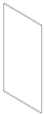 | |||||||
| Model 2 LT |  | 800 | 111.11 | 20 | 333.33 | 60 | 1, 1.5, 2 | |
| Model 3 LTH 1 | 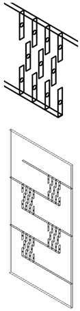 | 800 | 111.11 | 20 | 333.33 | 60 | 15, 10 | 1, 1.5, 2 |
| Model 4 LTH 2 | 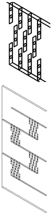 | 800 | 111.11 | 20 | 333.33 | 60 | 15, 10 | 1, 1.5, 2 |
| S.M | Boundary Name | Boundary Type | Value |
|---|---|---|---|
| 1 | Inlet | Mass flow | 0.021807, to 0.080591 kg/s |
| 2 | Outlet | Pressure | 0 Pa |
| 3 | Absorber | Wall heat flux | 1000 W/m2 |
| 4 | Isolator | Adiabatic wall | Wall no slip |
| 5 | Baffles | Adiabatic wall | Wall no slip |
| 6 | Side wall | Adiabatic wall | Wall no slip |
| Properties | Fluid (Air) | Absorber Plate and Baffles (Aluminum) |
|---|---|---|
| Density (kg/m3) | 1.167 | 2719 |
| Viscosity (kg/ms) | 1.85 × 10⁻⁵ | |
| Thermal conductivity (W/mk) | 0.0262 | 202.4 |
| Specific heat (J/kgk) | 1006 | 871 |
Disclaimer/Publisher’s Note: The statements, opinions and data contained in all publications are solely those of the individual author(s) and contributor(s) and not of MDPI and/or the editor(s). MDPI and/or the editor(s) disclaim responsibility for any injury to people or property resulting from any ideas, methods, instructions or products referred to in the content. |
© 2024 by the authors. Licensee MDPI, Basel, Switzerland. This article is an open access article distributed under the terms and conditions of the Creative Commons Attribution (CC BY) license (https://creativecommons.org/licenses/by/4.0/).
Share and Cite
Boussouar, G.; Rostane, B.; Aliane, K.; Ravi, D.; Gęca, M.J.; Gola, A. Study of the Thermal Performance of Solar Air Collectors with and without Perforated Baffles. Energies 2024, 17, 3812. https://doi.org/10.3390/en17153812
Boussouar G, Rostane B, Aliane K, Ravi D, Gęca MJ, Gola A. Study of the Thermal Performance of Solar Air Collectors with and without Perforated Baffles. Energies. 2024; 17(15):3812. https://doi.org/10.3390/en17153812
Chicago/Turabian StyleBoussouar, Ghizlene, Brahim Rostane, Khaled Aliane, Dineshkumar Ravi, Michał Jan Gęca, and Arkadiusz Gola. 2024. "Study of the Thermal Performance of Solar Air Collectors with and without Perforated Baffles" Energies 17, no. 15: 3812. https://doi.org/10.3390/en17153812
APA StyleBoussouar, G., Rostane, B., Aliane, K., Ravi, D., Gęca, M. J., & Gola, A. (2024). Study of the Thermal Performance of Solar Air Collectors with and without Perforated Baffles. Energies, 17(15), 3812. https://doi.org/10.3390/en17153812