Abstract
Inductive power transfer (IPT) technology is used in various applications owing to its safety features, robust environmental adaptability, and convenience. In some special applications, the charging pads are required to be as compact as possible to accommodate practical spatial requirements, and even size requirements dictate that the diameter of the charging pad matches the air gap. However, such requirements bring about a decrease in the transmission efficiency, power, and tolerance to misalignment of the system. In this paper, by comparing a double-sided inductor–capacitor–capacitor (LCC), double-sided inductor–capacitor–inductor (LCL), series–series (SS), and inductor–capacitor–capacitor–series (LCC-S) compensation topologies in IPT systems, we identified a double-sided LCC compensation topology that is suitable for weak coupling coefficients. Furthermore, this study modeled and simulated the typical parameters of coreless coils in circular power pads, such as the number of coil layers, turns, wire diameter, and wire spacing, to enhance the mutual inductance of the magnetic coupler during misalignment and long-distance transmission. A wireless charging system with 640 W output power was built, and the experimental results show that a maximum dc-dc efficiency of over 86% is achieved across a 200 mm air gap when the circular power pad with a diameter of 200 mm is well aligned. The experimental results show that using a suitable compensation topology and optimizing the charging pad parameters enables efficient IPT system operation when the coupling coefficient is 0.02.
1. Introduction
IPT technology has gained widespread adoption due to its advantages of high power and efficiency in near-field wireless power transfer, making it suitable for various applications such as electric vehicles [1,2,3,4,5], medical implant devices [6,7], and underwater vehicles [8,9,10]. However, in several narrow applications, such as inter-satellite modules, internal machinery with rotating components, or high-voltage transmission line monitoring equipment [11], the need arises for smaller charging pads to conserve space and reduce weight. As the size of coils decreases and the air gap increases, the coupling coefficient between the coils typically falls within the range of 0.015–0.03, which makes the transmission efficiency and stability of the system decrease. There is no doubt that optimizing coil design to enhance the coupling coefficient under large air gaps is crucial [12].
Many different compensation topologies have been proposed for tuning two coils at resonant frequency in order to work in a range of misalignment types or air gaps; these include four basic compensation topologies [13,14,15,16], LCC-LCC [1,2,3,4,17,18,19], LCL-LCL [20,21], and LCC-Series [9,22,23]. Usually, the constant-current output topologies suitable for wireless charging are the SS, LCL-LCL, and LCC-LCC compensation topologies. The resonant frequency of the SS compensation topology can be independent of the coupling coefficient and load [13,15], but the input impedance of the compensation topology is dependent on the coupling coefficient and load, which can be dangerous if misaligned or the load changes [16,24,25]. The design of an LCL compensation topology usually requires the compensation inductance value to be equal to the coil inductance value [20]. The LCC-LCC compensation topology has constant-current output, achieves a fixed operation frequency within a range of loads and air gaps, and is less sensitive to the variations of mutual inductance [4,18,19,26,27].
In an IPT system, the magnetic coupler plays an important role, and well-designed coupling coils and magnetic material core are essential. Many types of coil topologies have been proposed to enhance the coupling coefficient and tolerance to misalignment. Circular coils and rectangular coils are commonly used configurations in IPT systems. Several studies have focused on improving the performance of circular coils [28,29,30,31,32,33,34], while a method to enhance the quality factor (Q) of rectangular coils is reported in [35]. Additionally, Double D (DD) coils have been presented in [36], and they have been widely used in electric vehicle IPT systems due to their lower leakage flux from the outside of the coil and higher average flux path compared with other coil topologies [5,36,37,38,39]. In addition, there are also some methods available to increase the transmission distance by adding more coils [40,41] or designing new charging pads [11,42].
However, the conditions for these techniques are difficult to achieve efficient transmission in narrow engineering applications. Compared to previous literature, the primary contribution of this paper is the design methodology of a long-distance and efficient two-coil IPT system, which can be divided into two main aspects. First, it uses the typical parameters of the coreless coil such as the number of coil layers, turns, wire diameter, and wire spacing to establish a mathematic model in order to optimize the design of the multi-layer charging pads to save space and increase mutual inductance. Second, by comparing the outputs of commonly used compensation topologies under varying coupling coefficients, a double-sided LCC compensation topology suitable for weak couplings is selected.
This paper is structured as follows: Initially, the coupling coefficient of a charging pad composed of a single-layer circular coil and ferrite is simulated. Subsequently, double-sided LCC, double-sided LCL, SS, and LCC-S compensation topology wireless charging systems using the same charging pad diameter of 200 mm are designed to simulate changes in efficiency under different coupling coefficients or load, thereby identifying the compensation topology suitable for weak coupling IPT charging. Furthermore, this study proceeds to model and analyze the number of layers, turns, wire diameter, and wire spacing in coreless coils to optimize the charging pad design. Finally, a prototype circular charging pad with a diameter of 200 mm and a double-sided LCC compensation topology is built. It is verified that when the air gap is 200 mm and well aligned, the wireless charging system achieved an output power of 640 W with an efficiency exceeding 86%.
2. Comparison of Different Compensation Topologies
2.1. Magnetic Field Simulation of Charging Pad in Weak Coupling IPT System
An efficient IPT system necessitates the employment of suitably designed charging pads, as the coupling coefficient diminishes rapidly when the air gap is comparable to the diameter of the charging pad. While commonly used DD coils offer a higher average flux path compared to circular coils, circular coils are more suitable for weak coupling IPT systems due to their higher central magnetic flux density. The circular coils considered in this work for the charging pad of the primary transmitter and secondary receiver rely on magnetic field simulations of single-layer circular coils with ferrite cores to ascertain the mutual inductance and coupling coefficient between the coils across different air gaps. This preliminary analysis serves as foundational guidance for the development of the prototype charging pad discussed in Section 3.
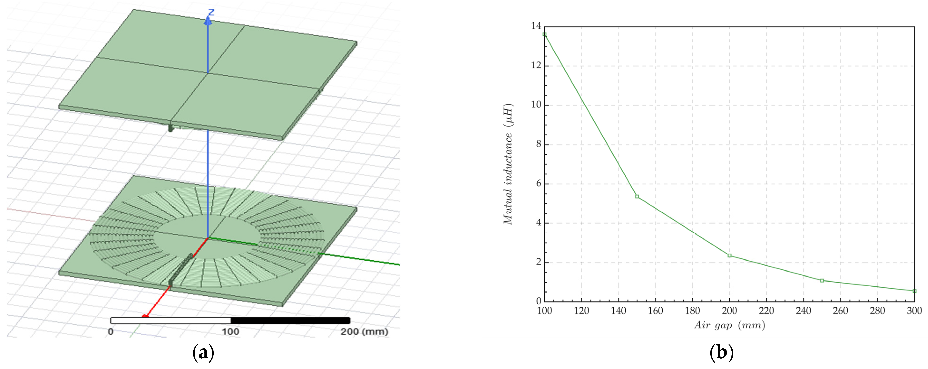
The circular coils employed for Ansys Maxwell magnetic field simulations consist of a single layer, comprising 17 turns, with a diameter of 200 mm. The Litz wire utilized has a diameter of 3 mm, and the wire spacing is set at 3.2 mm. Four pieces of ferrite were used, each with a size of 100 mm × 100 mm × 5 mm. The root mean square (RMS) value of the excitation current was 3 A. The operation frequency was 83 kHz, selected based on the frequency range specified in the ISO 19363:2020 standard [43] for wireless charging of electric vehicles.
Figure 1a illustrates a coreless circular coil with a self-inductance of 48 . The charging pad, when equipped with ferrite, has a self-inductance of 85 . Figure 1b shows that the mutual inductance of charging pads decreases rapidly as the air gap increases. When the air gap is 200 mm, the mutual inductance is 2.359 and the self-inductance is 85 , resulting in a coupling coefficient of less than 0.03 for air gaps greater than 200 mm. The simulation results suggest that a single-layer circular charging pad is suitable when the air gap is less than the radius of the circular coil. However, the coupling coefficient drops below 0.03 when the air gap equals the diameter of the charging pad, necessitating the use of multi-layered circular coils to maintain efficient IPT as the air gap increases.

Figure 1.
Magnetic simulation of circular charging pads. (a) Simulation models with an air gap of 200 mm; (b) mutual inductance of the charging pad under different air gaps.
2.2. Basic Characteristics of Different Compensation Topologies
The S and LCC compensation topologies are commonly used to realize IPT. With an increase in the air gap and misalignment, the coupling coefficient of the system is less than 0.03 and the dc-dc efficiency decreases rapidly. In this section, the model of compensation topology is established, and the output power and efficiency of different topologies under different coupling coefficients are analyzed.
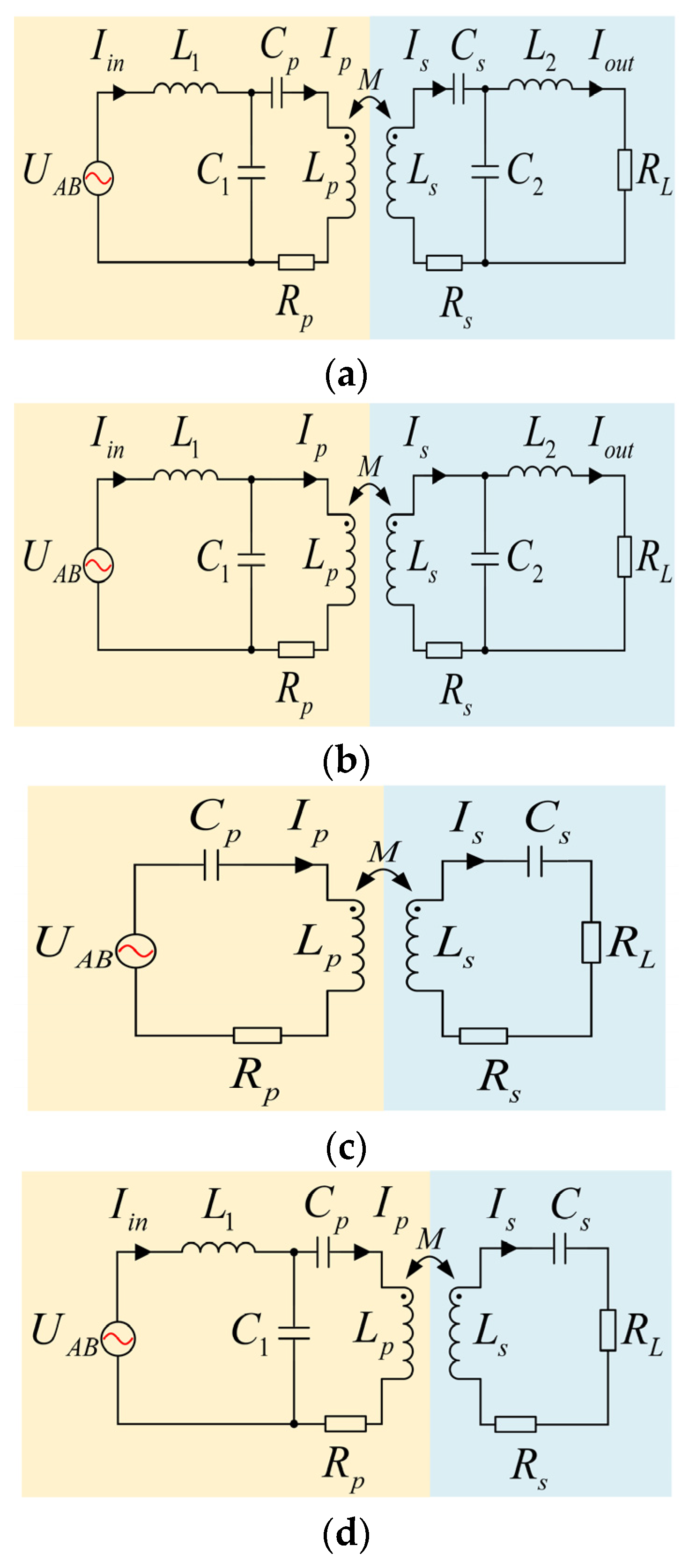
Figure 2 shows the different compensation topologies used to transfer power from the inverter to load resistance, RL. C1 and C2 are parallel compensation capacitors of the transmitter and receiver side, respectively. L1 and L2 represent the compensation inductance. Lp and Ls represent self-inductance, and associated transmitting and receiving coil resistances are represented by Rp and Rs. Cp and Cs are series compensation capacitors of Lp and Ls, respectively. Zs represents the equivalent impedance of the secondary circuit; Zr represents the impedance reflected by the secondary circuit to the primary circuit; Zp represents the overall impedance of the entire system after inversion. M represents mutual inductance between coils. ω0 represents the resonant angular frequency, ω0 = 2πf, and f represents the operation frequency of the system.
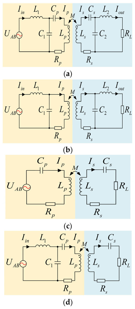
Figure 2.
Different compensation topologies of an IPT system. (a) Double-sided LCC compensation topology; (b) double-sided LCL compensation topology; (c) SS compensation topology; (d) LCC-S compensation topology.
k represents the coupling coefficient between the transmitting and receiving coils, and it is given by Equation (1):
In this paper, Lp and Ls have a larger self-inductance than the transmitting coil in Annex A of ISO 19363:2020, Lp = Ls = 285 . The capacitance and inductance values of the compensation topology are calculated according to Equation (2).
Drawing upon the previous literature and assuming coil self-inductance, we determined the parameters necessary for comparing these topologies at an equivalent output power. These parameters are summarized in Table 1.

Table 1.
Parameters of the double-sided LCC, SS, and LCC-S compensation topologies.
For ideal double-sided LCC, double-sided LCL, SS, and LCC-S compensated wireless charging systems operating at f0, the output power is calculated by:
and are the reflection impedance from the secondary side to the primary side of the double-sided LCC and double-sided LCL compensation topology, respectively.
The transmission efficiency can be calculated by Equation (5):
Figure 3 compares the efficiency of the double-sided LCC, double-sided LCL, SS, and LCC-S compensation topologies when only considering the equivalent resistance of the inductance.
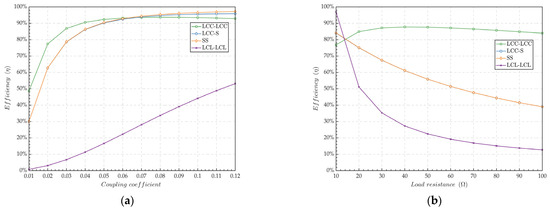
Figure 3.
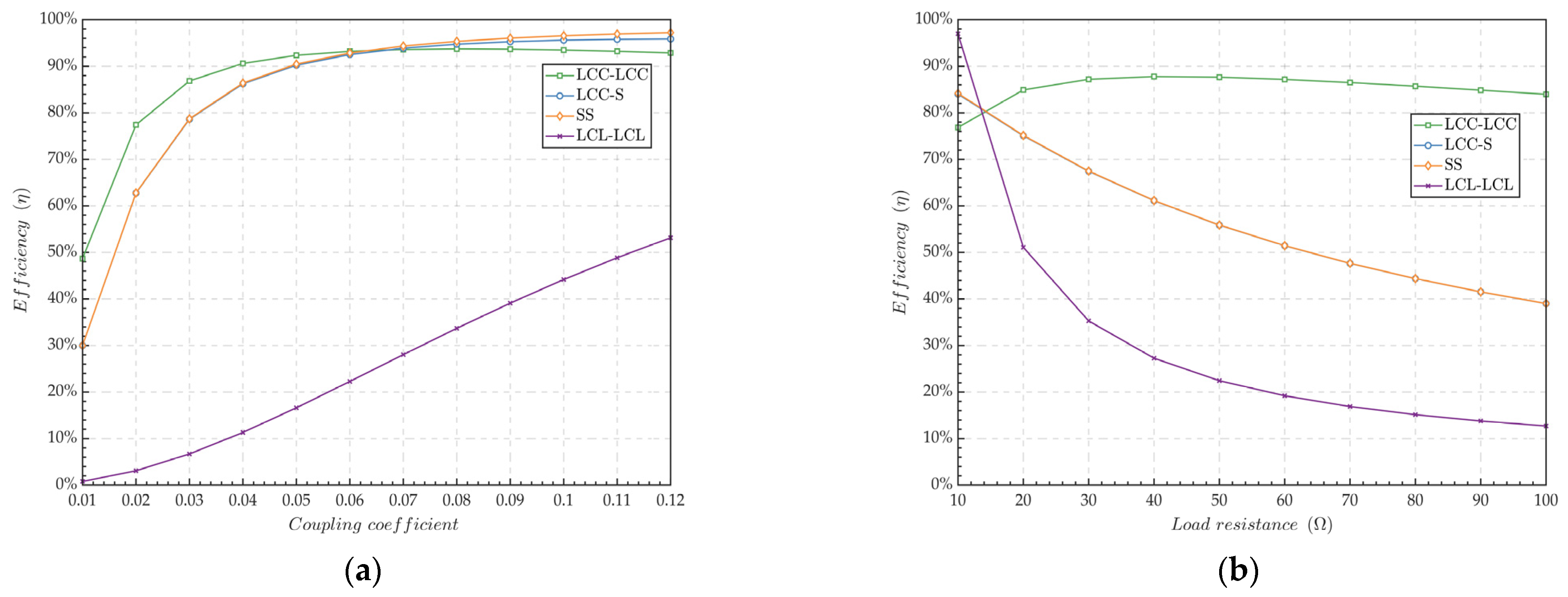
Influence of different parameters on transmission efficiency in LCC-LCC, LCL-LCL, LCC-S, and SS. (a) Only considering the equivalent resistance of the inductors and RL = 20; (b) k = 0.027.
Figure 3a shows that the double-sided LCC compensation topology exhibits higher efficiency compared to the LCL-LCL, LCC-S, and SS compensation topologies. Figure 3b shows that the double-sided LCC compensation topology achieves a higher average efficiency in comparison to the LCL-LCL, LCC-S, and SS compensation topologies under weak coupling conditions. Owing to the increase in Ip for the SS compensation and higher average transmission efficiency of double-sided LCC compensation under weak coupling coefficient, this paper selects the double-sided LCC compensation topology for the IPT system under weak coupling.
3. Modeling of Coupling Coils
3.1. Modeling of Coreless Coils
The k of charging pads is a significant parameter which is determined by the coils’ self-inductance and mutual inductance. Keeping k within a reasonable range is a significant condition of ensuring stable IPT. The self-inductance of the coil mainly depends on the outer diameter dout of the coil, the inner diameter din of the coil, the number of single-layer coil turns N, the number of coil layers m, the wire spacing Sw, and wire diameter Dw. The mutual inductance of the coils depends on the coil shape and relative position of the coil.
The self-inductance L of a regular polygon hollow coil can be calculated by the following Neumann formula [44]. L can be calculated by Equation (6):
where is the permeability of vacuum. The specific parameters are shown in Table 2.
Table 2.
Self-inductance parameters of different coreless coils.
The error of this method increases with the increase in the ratio between Sw and Dw of the coil. The fitting effect is more accurate when Sw is less than or equal to Dw. The error is 8% when Sw is three times Dw.
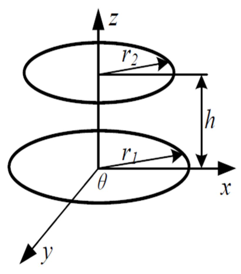
According to Maxwell’s theory, the M of the coupling coils is related to the coil current in a single period. Take an asymmetric, single-layer coupling coreless circular coil without misalignment as an example, as shown in Figure 4.
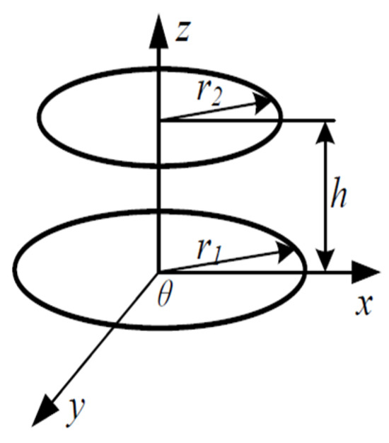
Figure 4.
Asymmetric single-layer coupling coreless circular coil without misalignment.
The M of the axisymmetric coupling coreless circular coil can be expressed as Equation (7) [45].
In Equation (7), the average radii of the two coils are r1 and r2, respectively, N1 and N2 are the turns of the two coils, and h is the air gap, where:
N1 and N2 are limited when the coil size is limited, so the number of coil layers m needs to be increased to improve L and M, and multiple single-layer coupling coils can simulate the multi-layer coil. According to Equation (6), the self-inductance of a coil with turn number N and layer number m can be expressed as Equation (9):
Equation (9) suggests that the self-inductance of a multi-layer coil is approximately equal to the self-inductance of a single-layer coil multiplied by the square of the coil layers. Nonetheless, the self-inductance of coils does not consistently rise with the coil layers due to wire spacing. Specifically, as the number of layers increases, the effective air gap between coupled coils expands, which in turn diminishes both coil self-inductance and mutual inductance. The self-inductance of multi-layer coupling coils with larger intervals can also be understood as the superposition of the self-inductance of each layer of coils and the internal mutual inductance, which can be expressed as Equation (10):
The M between multi-layer coupling coils can be understood as the mutual inductance superposition of multiple single-layer transmitting coils and multiple single-layer receiving coils. For coils with few layers, the mutual inductance formula of single-layer coupling coils can be directly calculated.
When the IPT system works at high-frequency alternating current, the relationship between the AC resistance of Litz wire and the operation frequency can be described by Equation (11) [46]:
where Kc is the length correction coefficient, usually 1.04~1.056; Lcoil is the length of the coil wire; Ns is the number of Litz wire strands; Ds is the single strand diameter of the Litz wire; H is the ratio of AC resistance to DC resistance of single strand wire; and is the conductivity of the Litz wire.
Equation (11) shows that the Lcoil of circular coil is smaller than that of rectangular coil for the same outer diameter and number of turns, so a circular coil is more suitable for weak coupling IPT. The output power of the double-sided LCC compensation topology can be obtained as:
The mutual inductance, self-inductance, and AC resistance of the coupling coils can be calculated using parameters such as the number of coil layers, turns, and wire spacing, etc.
3.2. Designing Coreless Coupling Coils to Optimize Mutual Inductance
The coupling coefficient is less than 0.03 when the coil diameter and air gap are equal, so M should be increased as much as possible to make the double-sided LCC compensation topology work efficiently under a weak coupling coefficient. In this work, the coil diameter and the air gap have been determined, so the coupling coefficient can only be improved by designing the number of coil layers, turns, wire diameter, and wire spacing. By using Equations (6) to (12), the coreless circular coil parameters of a weak coupling IPT system are calculated and designed. The detailed design process is shown in Figure 5.
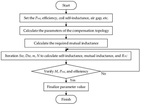
Figure 5.
Design process of coreless coupling coils.
M must be at least 7.7 to achieve k = 0.027 when Lp = Ls = 285 . Therefore, the mutual inductance of IPT should be improved by optimizing the Sw, Dw, m, and N of coupling coils, while keeping the coil self-inductance and air gap fixed.
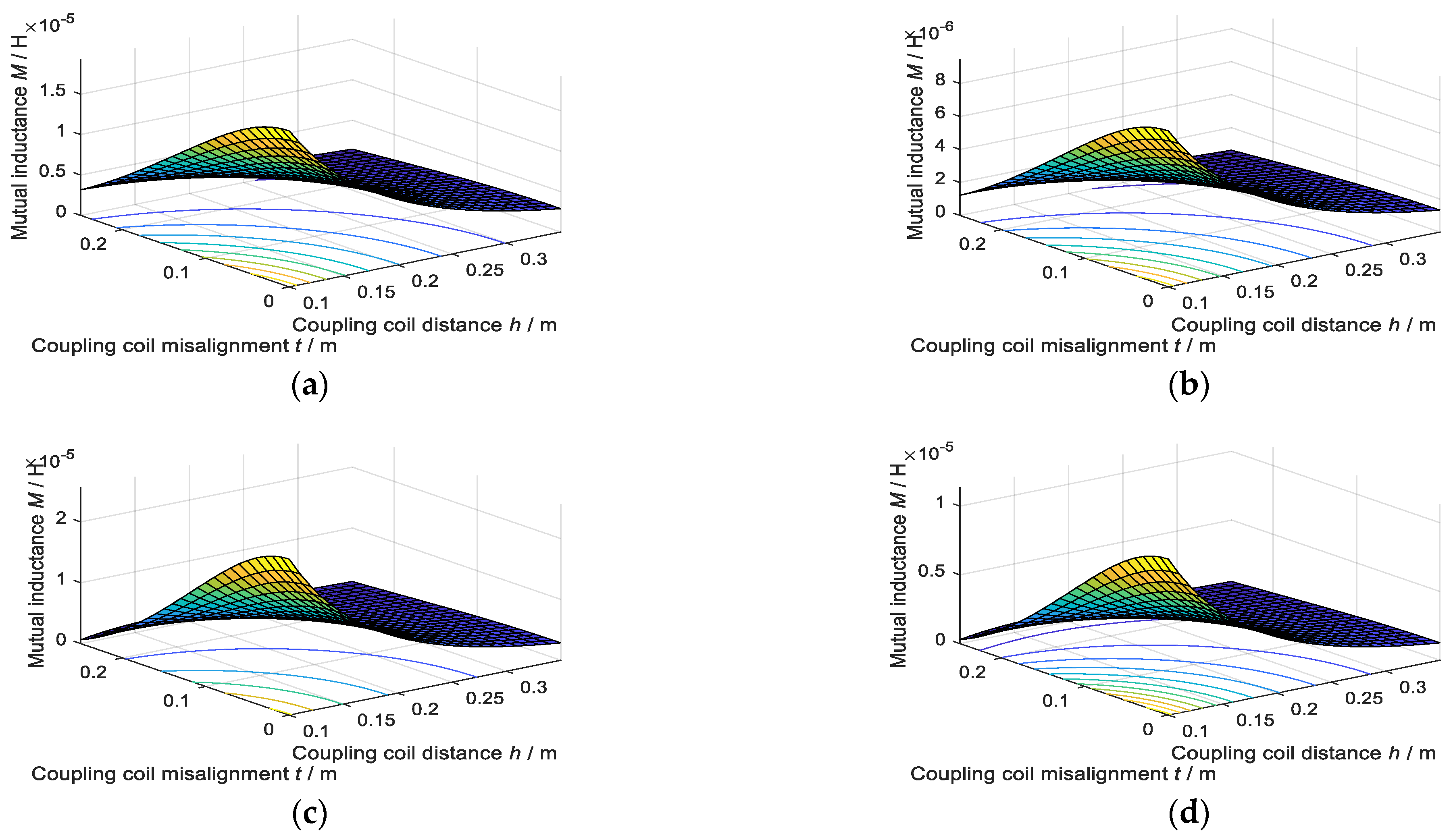
The maximum number of coil turns is limited because the coil diameter and wire diameter are limited. Figure 6 shows the influence of different Dw, Sw, and m values on the mutual inductance of the coreless circular coupling coils when N = 17. When the circular coil diameter and the air gap are 200 mm, the simulation results show that, when Dw = 2 mm, Sw = 0 mm, m = 2, and N = 17, the mutual induction reaches the target value in the case of positive alignment and changes slightly in the case of a small lateral misalignment, which is suitable for weak coupling coefficient IPT. The modeling of coreless circular coils helps determine the number of layers, turns, wire diameter, and wire spacing for the charging pad.
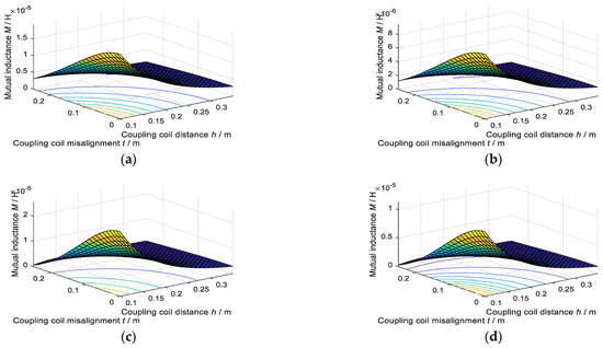
Figure 6.
Simulation of mutual inductance. (a) Dw = 2 mm, Sw = 0 mm, m = 2; (b) Dw = 2 mm, Sw = 2 mm, m = 3; (c) Dw = 2 mm, Sw = 2 mm, m = 2; (d) Dw = 2 mm, Sw = 4 mm, m = 3.
4. Experiment
Using the parameters in Table 3, a 640 W experimental platform for an IPT system was built.
Table 3.
Parameter values of IPT prototype.
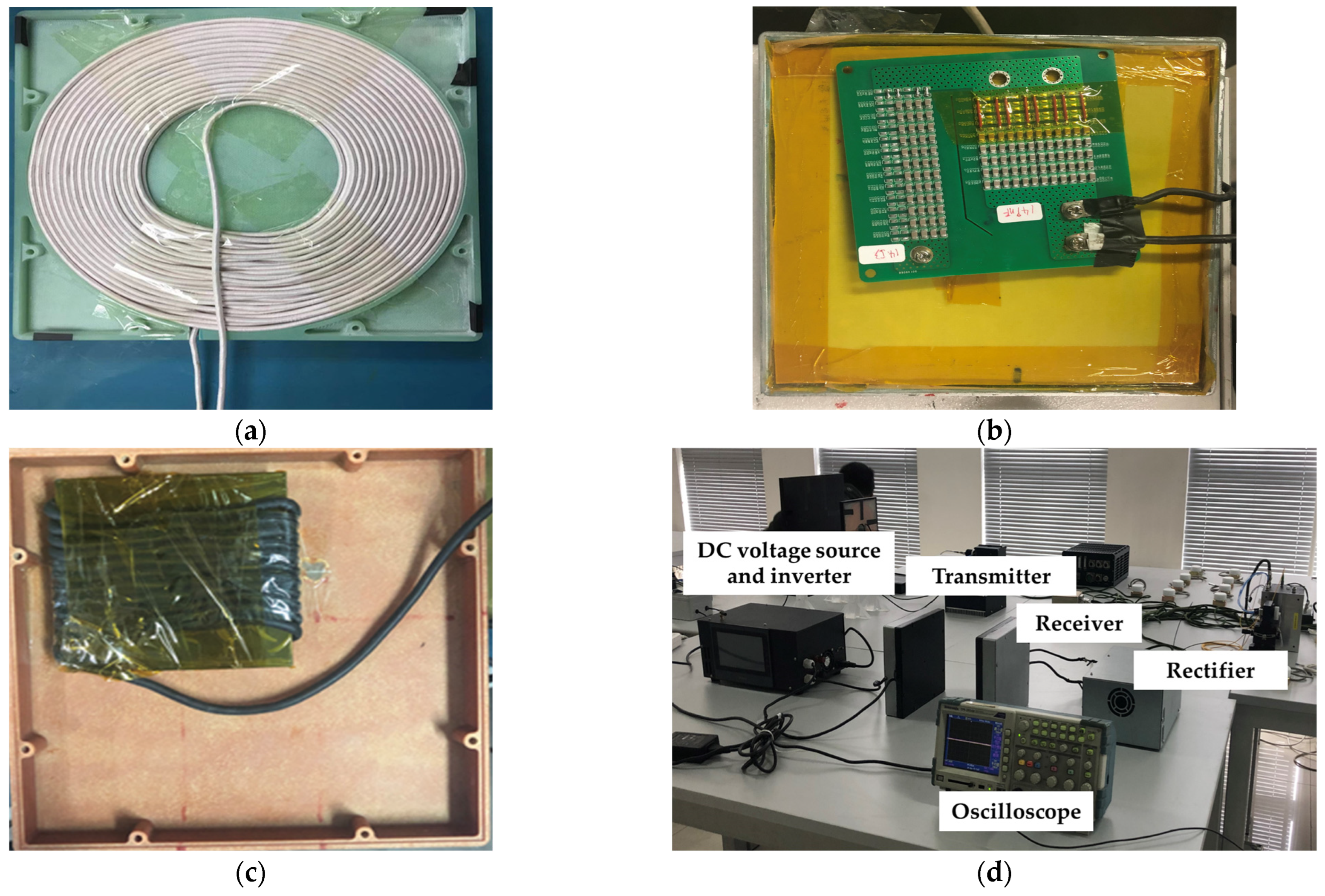
The charging pad is shown in Figure 7a. In Figure 7b, the capacitors C1 and Cs are shown mounted on a circuit board. L1, as shown in Figure 7c, is fabricated by winding Litz wire on ferrite. The experimental platform is shown in Figure 7d. The IPT characteristics of the double-sided LCC compensation topology under conditions of weak coupling coefficient are examined, with the air gap set at 200 mm for the test.
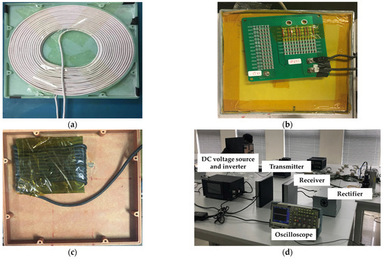
Figure 7.
(a) Charging pads; (b) capacitor in double-sided LCC compensation topology; (c) compensation inductance; (d) experimental platform.
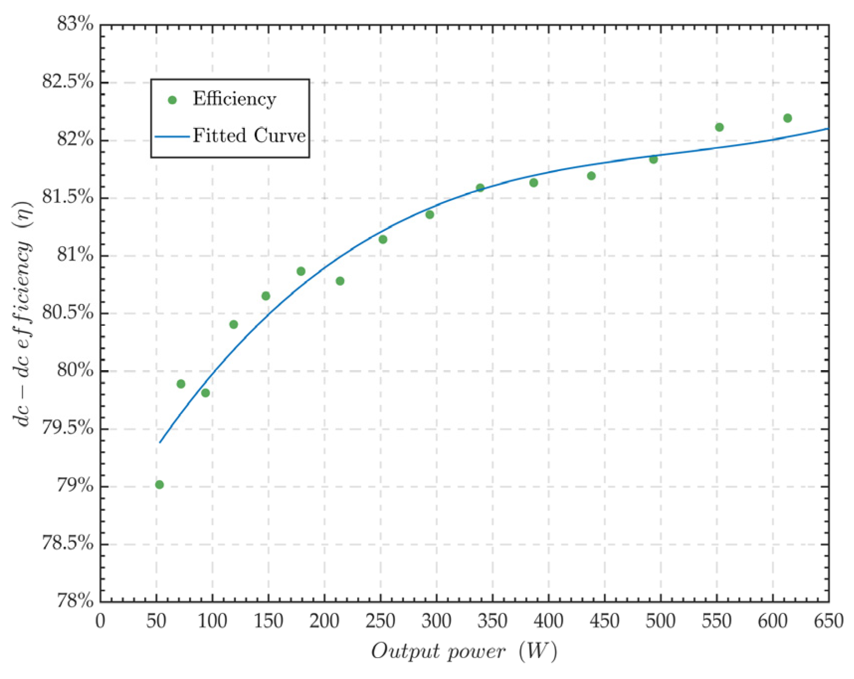
The efficiency from the DC voltage source to the DC electronic load, also known as dc-dc efficiency, of the IPT prototype with no misalignment, an air gap of 200 mm, and a coil diameter of 200 mm is shown in Figure 8 as a function of the output power. The experimental results show that the double-sided LCC IPT system can achieve stable power transmission under a weak coupling coefficient with the same coil diameter and air gap.
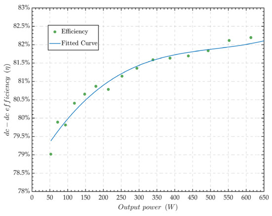
Figure 8.
Measured dc–dc efficiency at a 200 mm air gap.
The maximum dc-dc efficiency of the simulated system is 87.7%, whereas the maximum measured efficiency is 86.6%, owing to the presence of a rectifier, inverter, and non-ideal components within the circuit. However, the IPT prototype has the capability to demonstrate a dc-dc efficiency consistently exceeding 79% when the coupling coefficient is 0.02.
5. Discussion
This paper proposes a method utilizing multi-layer circular coils in conjunction with a double-sided LCC compensation topology to achieve efficient IPT under weak coupling conditions. The charging pads discussed in the literature usually employ single-layer coils [8,19]; however, the weak coupling occurring when the air gap equals the diameter of the single-layer coil leads to detuning and reduced efficiency. The modeling of coreless circular coils helps to optimize the number of layers, turns, wire diameters, and wire spacing of the charging pad to increase mutual inductance during misalignment and long-distance transmission. Table 4 provides a comparison of the performance of IPT prototypes.
Table 4.
Comparison of IPT systems.
This paper elucidates through simulations that single-layer coils are better suited when the air gap is less than the coil radius. Furthermore, a charging pad with enhanced mutual inductance via multi-layer coreless circular coils is employed and, in conjunction with double-sided LCC compensation topology, constitutes an IPT prototype capable of delivering 640 W output power. The experimental results show that this prototype achieves a maximum dc-dc efficiency of 86.6%, with the dc-dc efficiency consistently exceeding 79% when the coupling coefficient is 0.02.
Author Contributions
Y.C., X.Y. and S.Y. developed the idea of this study; Y.C. conducted the methodology, calculations, experiments, data analysis, and writing; X.Y. conducted the software and electromagnetic simulation; M.Z. conducted the investigation; S.Y. conducted the project administration and funding acquisition. All authors have read and agreed to the published version of the manuscript.
Funding
This research was financially supported by the National Key R&D Program of China, grant number 2021YFB2501700.
Data Availability Statement
Data are contained within the article.
Conflicts of Interest
The authors declare no conflicts of interest.
References
- Deng, Z.; Hu, H.; Su, Y.; Chen, F.; Xiao, J.; Tang, C.; Lin, T. Design of a 60-kW EV Dynamic Wireless Power Transfer System With Dual Transmitters and Dual Receivers. IEEE J. Emerg. Sel. Top. Power Electron. 2024, 12, 316–327. [Google Scholar] [CrossRef]
- Liu, C.; Zhang, Y.; Chen, H.; Wu, J.; He, X. Orthogonal-Frequency Simultaneous Wireless Power and Data Transfer for High-Power Wireless EV Charging. Energies 2024, 17, 1851. [Google Scholar] [CrossRef]
- Song, K.; Lan, Y.; Wei, R.; Yang, G.; Yang, F.; Li, W.; Jiang, J.; Zhu, C.; Li, Y. A Control Strategy for Wireless EV Charging System to Improve Weak Coupling Output Based on Variable Inductor and Capacitor. IEEE Trans. Power Electron. 2022, 37, 12853–12864. [Google Scholar] [CrossRef]
- Li, S.; Li, W.; Deng, J.; Nguyen, T.D.; Mi, C.C. A Double-Sided LCC Compensation Network and Its Tuning Method for Wireless Power Transfer. IEEE Trans. Veh. Technol. 2015, 64, 2261–2273. [Google Scholar] [CrossRef]
- Pearce, M.G.S.; Covic, G.A.; Boys, J.T. Reduced Ferrite Double D Pad for Roadway IPT Applications. IEEE Trans. Power Electron. 2021, 36, 5055–5068. [Google Scholar] [CrossRef]
- Zhu, H.; Tahir, M.; Wu, X.; Hu, S. High-Performance Wireless Power and Data Transmission System for Medical Implant Devices Using ASK Modulation. Energies 2024, 17, 731. [Google Scholar] [CrossRef]
- Chen, J.; Xu, J. A New Coil Structure for Implantable Wireless Charging System. Biomed. Signal Process. Control 2021, 68, 102693. [Google Scholar] [CrossRef]
- Chen, C.; Jiang, C.; Wang, Y.; Fan, Y.; Luo, B.; Cheng, Y. Compact Curved Coupler With Novel Flexible Nanocrystalline Flake Ribbon Core for Autonomous Underwater Vehicles. IEEE Trans. Power Electron. 2024, 39, 53–57. [Google Scholar] [CrossRef]
- Li, X.; Wu, Y.; Wang, H.; Dai, X.; Sun, Y.; Xiao, J.; Zuo, Z. A Magnetic Coupling Structure Design of Wireless Charging UAVs with Multidirectional Misalignment Improvement and Output Fluctuation Suppression. In Proceedings of the 2023 IEEE 6th International Electrical and Energy Conference (CIEEC), Hefei, China, 12–14 May 2023; pp. 4296–4299. [Google Scholar]
- Yan, Z.; Zhang, Y.; Kan, T.; Lu, F.; Zhang, K.; Song, B.; Mi, C.C. Frequency Optimization of a Loosely Coupled Underwater Wireless Power Transfer System Considering Eddy Current Loss. IEEE Trans. Ind. Electron. 2019, 66, 3468–3476. [Google Scholar] [CrossRef]
- Cai, C.; Wang, J.; Liu, R.; Fang, Z.; Zhang, P.; Long, M.; Hu, M.; Lin, Z. Resonant Wireless Charging System Design for 110-kV High-Voltage Transmission Line Monitoring Equipment. IEEE Trans. Ind. Electron. 2019, 66, 4118–4129. [Google Scholar] [CrossRef]
- Nguyen, T.-D.; Li, S.; Li, W.; Mi, C.C. Feasibility Study on Bipolar Pads for Efficient Wireless Power Chargers. In Proceedings of the 2014 IEEE Applied Power Electronics Conference and Exposition—APEC 2014, Fort Worth, TX, USA, 16–20 March 2014; pp. 1676–1682. [Google Scholar]
- Wang, C.-S.; Covic, G.A.; Stielau, O.H. Power Transfer Capability and Bifurcation Phenomena of Loosely Coupled Inductive Power Transfer Systems. IEEE Trans. Ind. Electron. 2004, 51, 148–157. [Google Scholar] [CrossRef]
- Villa, J.L.; Sallan, J.; Sanz Osorio, J.F.; Llombart, A. High-Misalignment Tolerant Compensation Topology For ICPT Systems. IEEE Trans. Ind. Electron. 2012, 59, 945–951. [Google Scholar] [CrossRef]
- Sohn, Y.H.; Choi, B.H.; Lee, E.S.; Lim, G.C.; Cho, G.-H.; Rim, C.T. General Unified Analyses of Two-Capacitor Inductive Power Transfer Systems: Equivalence of Current-Source SS and SP Compensations. IEEE Trans. Power Electron. 2015, 30, 6030–6045. [Google Scholar] [CrossRef]
- Patil, D.; McDonough, M.K.; Miller, J.M.; Fahimi, B.; Balsara, P.T. Wireless Power Transfer for Vehicular Applications: Overview and Challenges. IEEE Trans. Transport. Electrific. 2018, 4, 3–37. [Google Scholar] [CrossRef]
- Luo, S.; Yao, Z.; Zhang, Z.; Zhang, X.; Ma, H. Balanced Dual-Side LCC Compensation in IPT Systems Implementing Unity Power Factor for Wide Load Range and Misalignment Tolerance. IEEE Trans. Ind. Electron. 2023, 70, 7796–7809. [Google Scholar] [CrossRef]
- Cai, J.; Wu, X.; Sun, P.; Deng, Q.; Sun, J.; Zhou, H. Design of Constant-Voltage and Constant-Current Output Modes of Double-Sided LCC Inductive Power Transfer System for Variable Coupling Conditions. IEEE Trans. Power Electron. 2024, 39, 1676–1689. [Google Scholar] [CrossRef]
- Wang, X.; He, R.; Wang, H.; Liang, J.; Fu, M. Modified LCC Compensation and Magnetic Integration for Inductive Power Transfer. IEEE J. Emerg. Sel. Top. Power Electron. 2024, 12, 186–194. [Google Scholar] [CrossRef]
- Xia, C.; Sun, Q.; Li, X.; Hu, A.P. Robust μ-synthesis Control of Dual LCL Type IPT System Considering Load and Mutual Inductance Uncertainty. IEEE Access 2019, 7, 72770–72782. [Google Scholar] [CrossRef]
- Dongming, G.; Dangshu, W. Research on Transmission Characteristics of Dual LCL Resonance Compensation Topology in Wireless Charging System. In Proceedings of the 2021 IEEE 5th Information Technology, Networking, Electronic and Automation Control Conference (ITNEC), Xi’an, China, 15–17 October 2021; pp. 185–189. [Google Scholar] [CrossRef]
- Yang, J.; Zhang, X.; Zhang, K.; Cui, X.; Jiao, C.; Yang, X. Design of LCC-S Compensation Topology and Optimization of Misalignment Tolerance for Inductive Power Transfer. IEEE Access 2020, 8, 191309–191318. [Google Scholar] [CrossRef]
- Wang, H.; Sun, J.; Cheng, K.W.E. A Compact and Integrated Magnetic Coupler Design With Cross-Coupling Elimination Utilizing LCC-S Compensation Network for Building Attached Photovoltaic Systems. IEEE Trans. Magn. 2023, 59, 8401205. [Google Scholar] [CrossRef]
- Yang, S.; Yan, X.; He, H.; Yang, P.; Peng, Z.; Cui, H. Control Strategy for Vehicle Inductive Wireless Charging Based on Load Adaptive and Frequency Adjustment. Energies 2018, 11, 1222. [Google Scholar] [CrossRef]
- Li, W.; Zhao, H.; Deng, J.; Li, S.; Mi, C.C. Comparison Study on SS and Double-Sided LCC Compensation Topologies for EV/PHEV Wireless Chargers. IEEE Trans. Veh. Technol. 2016, 65, 4429–4439. [Google Scholar] [CrossRef]
- Lu, F.; Hofmann, H.; Deng, J.; Mi, C. Output Power and Efficiency Sensitivity to Circuit Parameter Variations in Double-Sided LCC-Compensated Wireless Power Transfer System. In Proceedings of the 2015 IEEE Applied Power Electronics Conference and Exposition (APEC), Charlotte, NC, USA, 15–19 March 2015; pp. 597–601. [Google Scholar]
- Shin, Y.; Woo, S.; Lee, C.; Rhee, J.; Huh, S.; Ahn, S. Determination of Current Ratio to Minimize Power Losses of Coils in Wireless Power Transfer System with Double-Sided LCC Topology. In Proceedings of the 2022 Wireless Power Week (WPW), Bordeaux, France, 5–8 July 2022; pp. 95–98. [Google Scholar]
- Budhia, M.; Covic, G.A.; Boys, J.T. Design and Optimization of Circular Magnetic Structures for Lumped Inductive Power Transfer Systems. IEEE Trans. Power Electron. 2011, 26, 3096–3108. [Google Scholar] [CrossRef]
- Bosshard, R.; Kolar, J.W. Inductive Power Transfer for Electric Vehicle Charging: Technical Challenges and Tradeoffs. IEEE Power Electron. Mag. 2016, 3, 22–30. [Google Scholar] [CrossRef]
- Long, B.R.; Miller, J.M.; Daga, A.; Schrafel, P.C.; Wolgemuth, J. Which Way for Wireless Power: High Q or High k? In Proceedings of the 2016 IEEE PELS Workshop on Emerging Technologies: Wireless Power Transfer (WoW), Knoxville, TN, USA, 4–6 October 2016; pp. 6–10. [Google Scholar]
- Xia, C.; Li, X.; Sun, Q.; Liao, Z.; Hu, A.P. Improving Magnetic Coupling Characteristics of Square Coupler ICPT System by Round Corner Design. Electr. Eng. 2020, 102, 1021–1033. [Google Scholar] [CrossRef]
- Dharani, M.; Ravi, K. An Analytical Study for the Realization of Maximum Efficiency in Wireless Charging System Using a Circular Inductive Coil. In Proceedings of the 2023 Innovations in Power and Advanced Computing Technologies (i-PACT), Kuala Lumpur, Malaysia, 8–10 December 2023; pp. 1–7. [Google Scholar]
- Li, Y.; Jiang, S.; Liu, X.-L.; Li, Q.; Dong, W.-H.; Liu, J.-M.; Ni, X. Influences of Coil Radius on Effective Transfer Distance in WPT System. IEEE Access 2019, 7, 125960–125968. [Google Scholar] [CrossRef]
- Kim, D.-H.; Kim, J.; Park, Y.-J. Optimization and Design of Small Circular Coils in a Magnetically Coupled Wireless Power Transfer System in the Megahertz Frequency. IEEE Trans. Microw. Theory Tech. 2016, 64, 2652–2663. [Google Scholar] [CrossRef]
- Awuah, C.M.; Danuor, P.; Moon, J.-I.; Jung, Y.-B. Novel Coil Design and Analysis for High-Power Wireless Power Transfer with Enhanced Q-Factor. Sci. Rep. 2023, 13, 4187. [Google Scholar] [CrossRef]
- Budhia, M.; Boys, J.T.; Covic, G.A.; Huang, C.-Y. Development of a Single-Sided Flux Magnetic Coupler for Electric Vehicle IPT Charging Systems. IEEE Trans. Ind. Electron. 2013, 60, 318–328. [Google Scholar] [CrossRef]
- Zhang, W.; White, J.C.; Abraham, A.M.; Mi, C.C. Loosely Coupled Transformer Structure and Interoperability Study for EV Wireless Charging Systems. IEEE Trans. Power Electron. 2015, 30, 6356–6367. [Google Scholar] [CrossRef]
- Bosshard, R.; Iruretagoyena, U.; Kolar, J.W. Comprehensive Evaluation of Rectangular and Double-D Coil Geometry for 50 kW/85 kHz IPT System. IEEE J. Emerg. Sel. Top. Power Electron. 2016, 4, 1406–1415. [Google Scholar] [CrossRef]
- Mohammad, M.; Choi, S. Optimization of Ferrite Core to Reduce the Core Loss in Double-D Pad of Wireless Charging System for Electric Vehicles. In Proceedings of the 2018 IEEE Applied Power Electronics Conference and Exposition (APEC), San Antonio, TX, USA, 4–8 March 2018; pp. 1350–1356. [Google Scholar]
- Cheng, C.; Zhou, Z.; Li, W.; Deng, Z.; Mi, C.C. A Power Relay System With Multiple Loads Using Asymmetrical Coil Design. IEEE Trans. Ind. Electron. 2021, 68, 1188–1196. [Google Scholar] [CrossRef]
- Lu, F.; Zhang, H.; Li, W.; Zhou, Z.; Zhu, C.; Cheng, C.; Deng, Z.; Chen, X.; Mi, C.C. A High-Efficiency and Long-Distance Power-Relay System With Equal Power Distribution. IEEE J. Emerg. Sel. Top. Power Electron. 2020, 8, 1419–1427. [Google Scholar] [CrossRef]
- Cai, C.; Wang, J.; Jing, H.; Zhang, F.; Zhang, P.; Fang, Z.; Zhou, Y.-G. Universal Wireless Powered Terminals for Robust Overhead Transmission Line Monitoring. IET Power Electron. 2019, 12, 3739–3748. [Google Scholar] [CrossRef]
- ISO 19363:2020; Electrically Propelled Road Vehicles—Magnetic Field Wireless Power Transfer—Safety and Interoperability Requirements. International Organization for Standardization: Geneva, Switzerland, 2020.
- Mohan, S.S.; del Mar Hershenson, M.; Boyd, S.P.; Lee, T.H. Simple Accurate Expressions for Planar Spiral Inductances. IEEE J. Solid-State Circuits 1999, 34, 1419–1424. [Google Scholar] [CrossRef]
- Bieler, T.; Perrottet, M.; Nguyen, V.; Perriard, Y. Contactless Power and Information Transmission. IEEE Trans. Ind. Appl. 2002, 38, 1266–1272. [Google Scholar] [CrossRef]
- Väisänen, V.; Hiltunen, J.; Nerg, J.; Silventoinen, P. AC Resistance Calculation Methods and Practical Design Considerations When Using Litz Wire. In Proceedings of the IECON 2013—39th Annual Conference of the IEEE Industrial Electronics Society, Vienna, Austria, 10–13 November 2013; pp. 368–375. [Google Scholar]
- Wang, W.; Zhu, Z.; Wang, Q.; Hu, M. Optimisation Design of Real-Time Wireless Power Supply System Overhead High-Voltage Power Line. IET Electr. Power Appl. 2019, 13, 206–214. [Google Scholar] [CrossRef]

Disclaimer/Publisher’s Note: The statements, opinions and data contained in all publications are solely those of the individual author(s) and contributor(s) and not of MDPI and/or the editor(s). MDPI and/or the editor(s) disclaim responsibility for any injury to people or property resulting from any ideas, methods, instructions or products referred to in the content. |
© 2024 by the authors. Licensee MDPI, Basel, Switzerland. This article is an open access article distributed under the terms and conditions of the Creative Commons Attribution (CC BY) license (https://creativecommons.org/licenses/by/4.0/).