Abstract
The role of pumped storage in global energy structure transformation is becoming increasingly prominent. This article introduces a flexible excitation system based on fully controlled device converters into pumped storage units (PSUs). It can address the issues of insufficient excitation capacity and limited stability associated with traditional thyristor excitation systems. The study focuses on linear active disturbance rejection control (LADRC) for the flexible excitation control system of pumped storage units and utilizes intelligent optimization algorithms to optimize the controller parameters. This addresses the inherent problem of traditional PID controllers, which are unable to alleviate the trade-off between response speed and overshoot. At the same time, the robustness and anti-interference of the control system are improved, effectively enhancing the performance of the pumped storage flexible excitation control system. Simulation verifies the feasibility and superiority of the proposed method.
1. Introduction
Pumped storage is currently the largest and most economical large-scale energy storage method. It undertakes various functions in the power system, such as peak shaving and valley filling, phase modulation and frequency regulation, emergency backup, and black start. The flexible operation and rapid response of pumped storage make it an important guarantee for the safe and stable operation of the power grid and the large-scale consumption of new energy sources such as photovoltaic and wind power. It is known as the “super power bank” of the power system [1]. The development of pumped storage energy is an important strategic measure to build a modern energy system that is clean, low-carbon, safe, economically efficient, supply–demand-coordinated, flexible, and intelligent [2].
As a core component of the synchronous motor, the excitation system is an important link in the conversion of electrical energy and mechanical energy. At present, fixed-speed PSUs generally adopt a self-excited static excitation system based on thyristors, because it has the advantages of simple wiring and fast dynamic response [3]. However, when a short circuit fault occurs in the power grid, its excitation capacity is limited by the terminal voltage and can only absorb reactive power from the system, making it difficult to meet the high requirements of the new power system for the voltage stability and power angle stability of PSUs. The flexible excitation system based on fully controlled device converters can maintain the excitation voltage better and has stronger excitation ability through its own boosting characteristics and constant DC voltage control. Meanwhile, power decoupling control can provide dual damping channels with stronger damping support capabilities [4,5,6,7]. When the flexible excitation system is adopted, the voltage support capacity and damping support capacity of PSUs can be effectively improved, which helps PSUs play a better role in the new power system.
Excitation control is a key factor in leveraging the performance of flexible excitation systems. Since the emergence of flexible excitation systems, many scholars have conducted research on control strategies for flexible excitation systems. Reference [6] studied the basic principle of damping control for flexible excitation systems based on voltage source converters, and analyzed the mechanism of improving power system damping by flexible excitation systems. Reference [8] studied the basic control strategy of a flexible excitation system based on a multi-level voltage source inverter. Reference [4] studied the linear optimal excitation control strategy for flexible excitation systems, and coordinated the design of power system stabilizers and reactive power damping controllers. Reference [9] studied a multivariable feedback linearization control strategy for flexible excitation systems, achieving the goal of simultaneously controlling rotor angle and stabilizing machine terminal voltage. Reference [10] studied the excitation control strategy of flexible excitation systems based on intelligent algorithms. Reference [11] studied the optimization design method of flexible excitation systems to improve the stability of the power system. Reference [7] studied the coordinated optimization method of adaptive limiting voltage reactive power control based on flexible excitation systems. Reference [12] studied the control method of flexible excitation systems for improving the transient stability characteristics of the receiving end power grid. Reference [13] studied the control method of flexible excitation systems to enhance the damping of the power system. The control methods for flexible excitation systems mentioned above have their own advantages and limitations. Therefore, exploring the use of new excitation control methods to fully leverage the performance and tap into the potential of flexible excitation systems is of great research significance.
Reference [14], in response to the limitations of classical PID controllers, absorbed the essence of error elimination in classical PID controllers while introducing an extended state observer to obtain the total disturbance of the control object (including external and internal disturbances) and provide compensation, thus proposing active disturbance rejection control technology (ADRC). ADRC not only improves the dynamic and static performance of the system, but also has strong robustness and anti-interference ability. However, its structure is complex, and there are many parameters that need to be tuned. Therefore, reference [15] proposed linear active disturbance rejection control (LADRC), which simplified the structure of the controller and transformed parameter design into bandwidth selection, promoting the widespread application of active disturbance rejection control. By combining LADRC with excellent control performance and flexible excitation systems with excellent operational performance, the performance of flexible excitation systems can be fully utilized, their potential can be further explored, and their application in PSUs can be promoted. At the same time, this can also promote the application of LADRC technology in power systems.
In summary, Section 2 of this article first establishes a pumped storage unit model based on a flexible excitation system, and proposes the LADRC strategy for it. In Section 3, in order to solve the problem of the difficult tuning of LADRC parameters, intelligent algorithms are used to optimize the controller parameters. Section 4 finally verifies the feasibility and superiority of the LADRC strategy for the pumped storage flexible excitation system through simulation.
2. Control Strategy for Flexible Excitation System of PSU Based on LADRC
2.1. Structure of Single-Machine Infinite Bus System Based on Flexible Excitation System
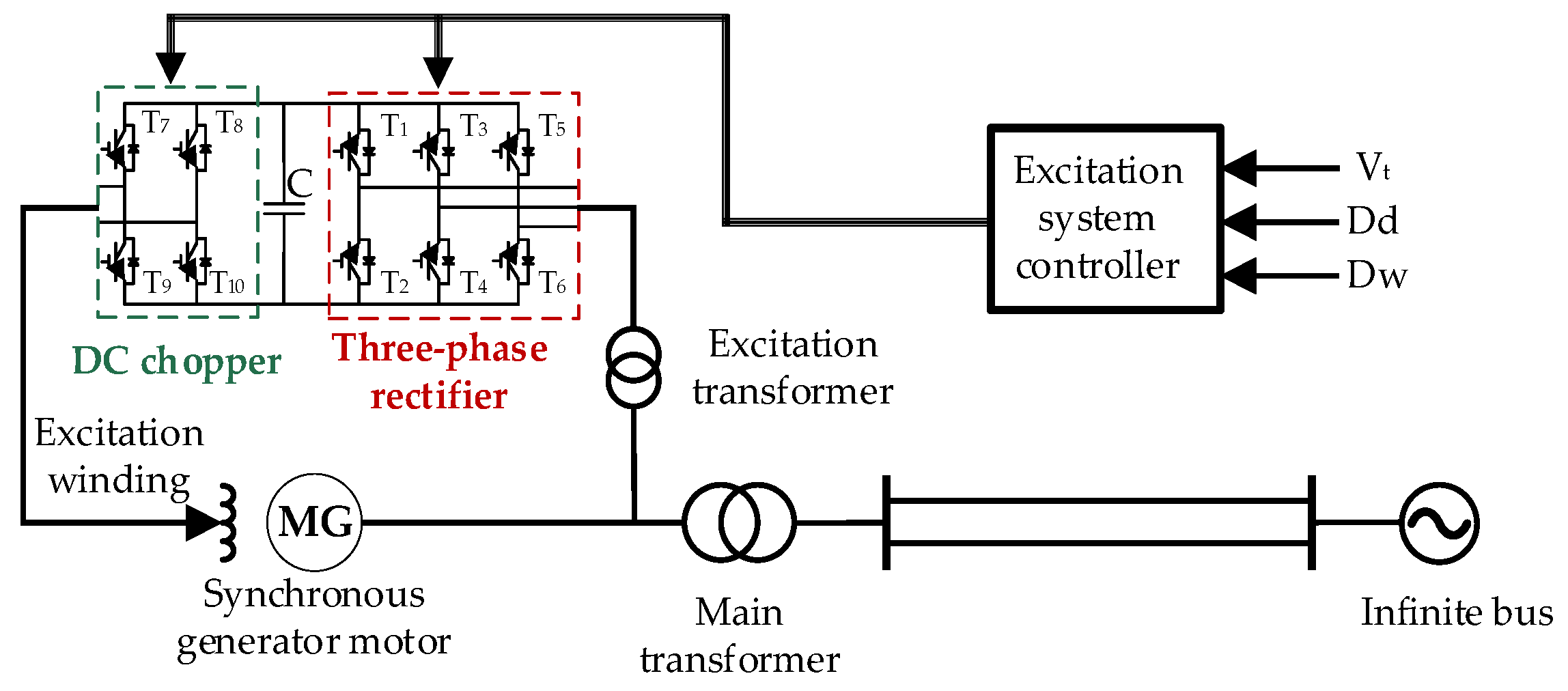
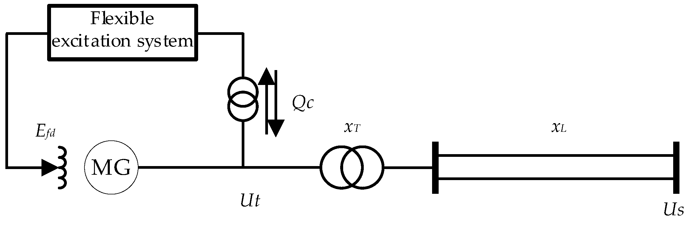
The flexible excitation system is divided into voltage source converter (VSC) and current source converter (CSC) based on the different fully controlled device converters used. Due to the wider application of the VSC type compared to the CSC type [16,17,18], a VSC-type flexible excitation system was used for analysis. Figure 1 shows the structure of a pumped storage single-machine infinite bus system based on the VSC-type flexible excitation system.

Figure 1.
Structure of single-machine infinite bus system based on VSCtype flexible excitation system.
The VSC-type flexible excitation system consists of a three-phase rectifier, a DC capacitor, a DC chopper, and a corresponding controller. Due to the use of fully controlled devices in the rectifier, the active and reactive power decoupling of the converter can be achieved, that is, the reactive power exchanged with the unit terminal can be controlled while controlling the excitation voltage. Therefore, the use of a flexible excitation system in a PSU can effectively improve the voltage support capacity and damping support capacity of the unit.
2.2. Mathematical Model of Pumped Storage Unit Based on Flexible Excitation System
On the basis of the structure of the pumped storage single machine infinite bus system based on the flexible excitation system mentioned above, the mathematical model of the single-machine infinite bus system for the generation/motor of the PSU and flexible excitation system are established, which lays a theoretical and model foundation for the subsequent research on flexible excitation control strategies.
2.2.1. Mathematical Model of Generation/Motor
In practical power system dynamic analysis, when considering the dynamics of the excitation system, the simplest and most practical one is the third-order model of the synchronous generator, namely, the first-order equation of the excitation winding and the second-order equation of rotor motion [19], which can be expressed as:
where δ is the generator power angle, ω is the generator speed, Mm is the generator mechanical torque, Me is the generator electromagnetic torque, D is the damping coefficient, TJ is the rotor inertia time constant, E’q is the q-axis transient electromotive force, Efd is the excitation voltage, Eq is the q-axis electromotive force, and T’d0 is the rotor open circuit time constant.
2.2.2. Mathematical Model of Flexible Excitation System
An important difference between a flexible excitation system and a conventional thyristor excitation system is that the flexible excitation system can achieve decoupling control through a fully controlled converter, thereby injecting or absorbing reactive power into the power system through the generator terminal. The main difference in its mathematical model also comes from this [4]. Shown in Figure 2 is an equivalent model of a pumped storage single-machine infinite bus system based on a flexible excitation system.

Figure 2.
Equivalent model of pumped storage single-machine infinite system based on flexible excitation system.
- (1)
- Generating conditions
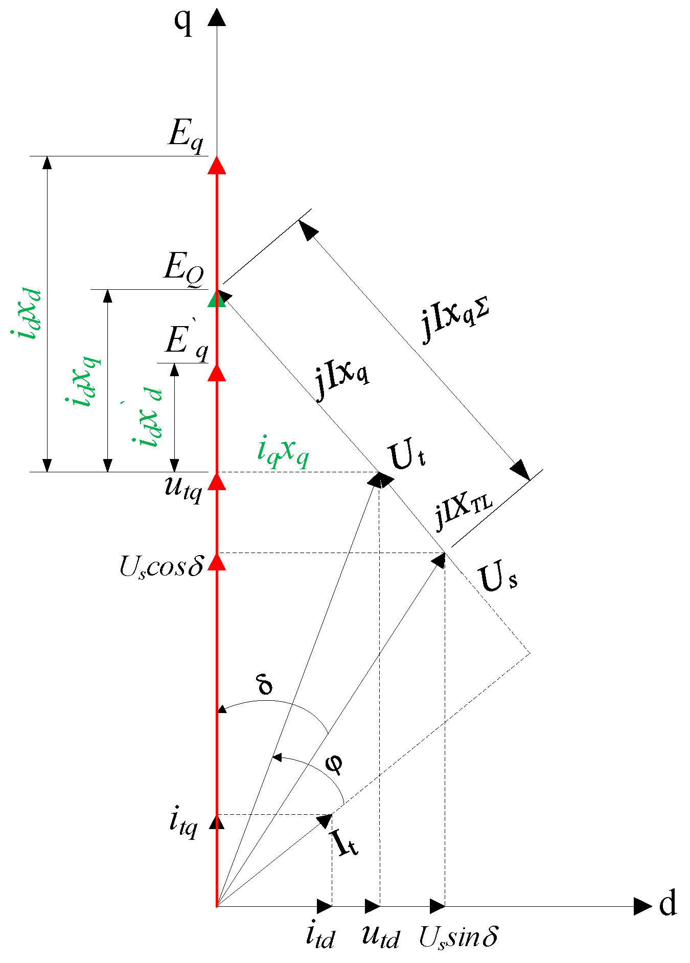
When the generator motor operates under generation conditions, the electrical vector diagram of the system described in Figure 2 is shown in Figure 3.

Figure 3.
Vector diagram of single-machine infinite bus system with pumped storage flexible excitation system under generating conditions.
The difference between a flexible excitation system and a conventional excitation system is that the former can exchange power with the generator through VSC. Assuming that the flexible excitation system injects power in the positive direction into the generator, there are:
where Pi and Qi represent the active power and reactive power injected into the generator by the flexible excitation system, respectively. For the convenience of deduction and understanding, BiP and BiQ are defined to, respectively, express the equivalent admittance of active power and reactive power injected into the flexible excitation system, and their expressions are as follows:
The flexible excitation system can only exchange reactive power with the generator without energy storage, BiP = 0, and linearize around the steady-state values of each variable. Further organization can obtain the third-order linearization model state equation of the synchronous motor as follows:
The specific expressions for each coefficient are:
where subscript 0 represents the steady-state values of each electrical quantity.
At the same time, the relationship between electrical quantities such as electromagnetic torque increment, q-axis electromotive force increment, terminal voltage increment, transient electromotive force increment, synchronous motor power angle increment, excitation voltage increment, and equivalent admittance increment of reactive power injection can be obtained:
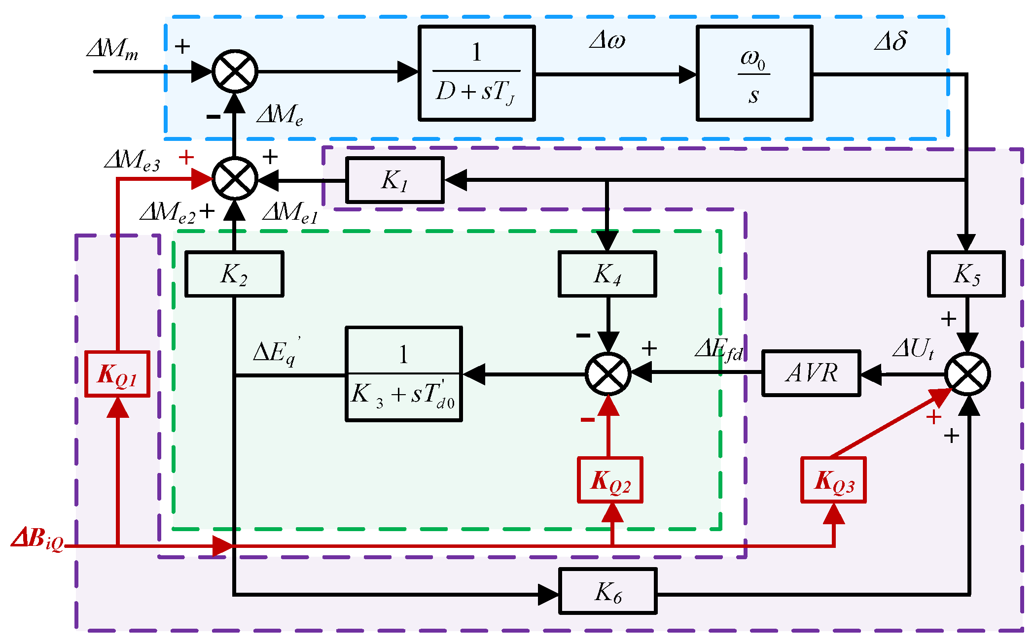
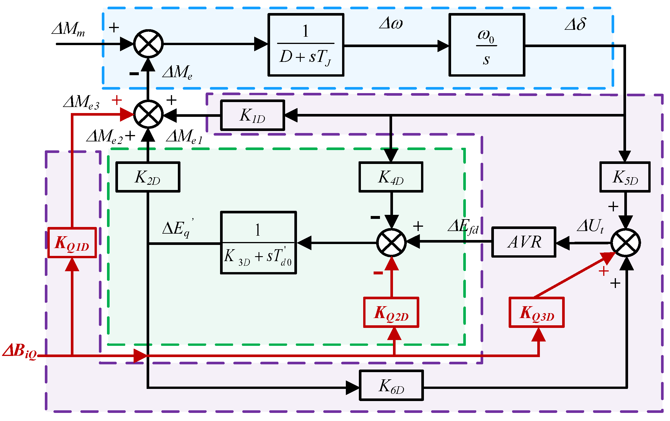
The Philips–Heffron model of the single-machine infinite bus system of the pumped storage flexible excitation system under power generation conditions can be obtained, as shown in Figure 4.
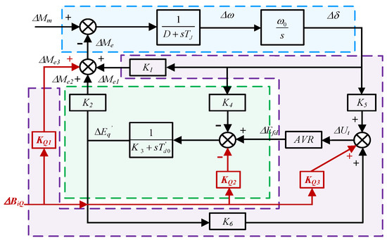
Figure 4.
Philips–Heffron model under generating conditions.
Figure 4 clearly illustrates the profound mechanism of the effect and influence of the flexible excitation system on the synchronous motor. The blue box in Figure 4 represents the electromechanical operation equation of the synchronous motor, including the Δw generated by the motor’s ΔMe and the resulting Δδ. The part inside the purple box is the module for generating synchronous torque ΔMe1 and exchanging reactive power torque ΔMe3 at the machine terminal, as well as the excitation control system. Δδ passes through K5, ΔE′q passes through K6, and exchanging reactive power at the machine terminal passes through KQ3, resulting in ΔUt and generating ΔEfd after passing through the excitation control system. The part inside the green box is the excitation torque generation module of the synchronous motor. Δδ undergoes armature reaction, ΔBiQ undergoes reactive power exchange at the machine terminal, and ΔEfd generates ΔE’q through the synchronous motor, which in turn generates excitation torque ΔMe2.
- (2)
- Pumping conditions
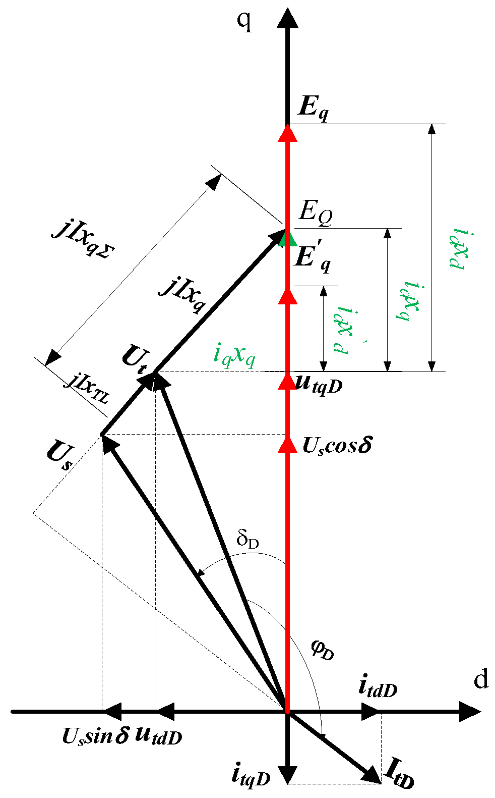
When the generator motor operates under pumping conditions, according to generator conventions, the electrical vector diagram of the system described in Figure 2 is shown in Figure 5.

Figure 5.
Vector diagram of single-machine infinite bus system with pumped storage flexible excitation system under pumping conditions.
From the comparison between the vector diagram under pumping conditions and the vector diagram under generation operating conditions, it can be seen that under the same parameters and corresponding symmetrical electrical vectors, the power angle between the generation operating conditions and the pumping operating conditions is opposite, and the sum of the angles between the current and the q-axis is 180° [19]:
where the subscript D represents the electrical quantity under pumping conditions for differentiation.
By substituting the above relationship into the specific expressions of each coefficient, it can be concluded that:
Similarly, the Philips–Heffron model for a single-machine infinite bus system of a pumped storage flexible excitation system under pumping conditions can be obtained, as shown in Figure 6.

Figure 6.
Philips–Heffron model under pumping conditions.
2.3. Principle of LADRC
In the design of excitation control for synchronous motors, the synchronous motor and excitation system can be simplified as an inertial system, which is a second-order system as a whole [20]. The state equation can be expressed as:
where b0 represents the gain coefficient and f is the combination of unknown system dynamics and external disturbances, which is assumed to be unknown in LADRC design and is called the total disturbance.
The core of LADRC is the extended state observer, which utilizes the extended state to estimate the total disturbance in real time [21]. Let:
There are:
Among them:
For the above system, the following Luenberger Extended State Observer (ESO) is designed. The input of ESO includes controller output u(t) and system output y(t), and the output of ESO is an estimated value of the system state. There are:
where L0 = [β1, β2, β3]T is the gain of the observer, and then:
The following control laws can be used to compensate for the “total disturbance”:
where r(t) is the reference value signal, is the expansion signal of the reference value, composed of the reference value and its differential signal, and K0 is the controller gain matrix.
In summary, the state equation of the second-order LADRC system is:
Using the concept of controller bandwidth [21], the poles of the observer can be configured to w0 and the poles of the controller can be configured to wc, so that the gain matrices of the observer and controller are:
Therefore, for the design of LADRC, only the order p of the control object needs to be known. The controller structure is fixed and simple, and only three parameters (observer bandwidth w0, controller bandwidth wc, and high-frequency gain b0) need to be adjusted. Therefore, LADRC is easy to adjust and implement in engineering.
2.4. LADRC Scheme for Flexible Excitation System of PSU
The LADRC scheme for the flexible excitation system of the PSU can be divided into upper system layer, middle converter layer, and lower device layer.
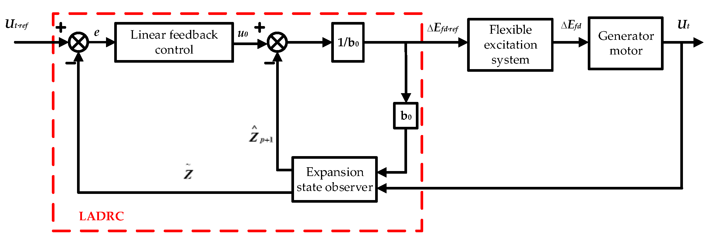
The control objective of the upper system layer is to stabilize the terminal voltage under normal or abnormal working conditions. The LADRC proposed in 2.3 is adopted. The upper LADRC provides reference signals for the control of the next layer converter. Based on the above analysis, the LADRC block diagram of the system layer can be obtained as shown in Figure 7.

Figure 7.
Block diagram of LADRC at the system level.
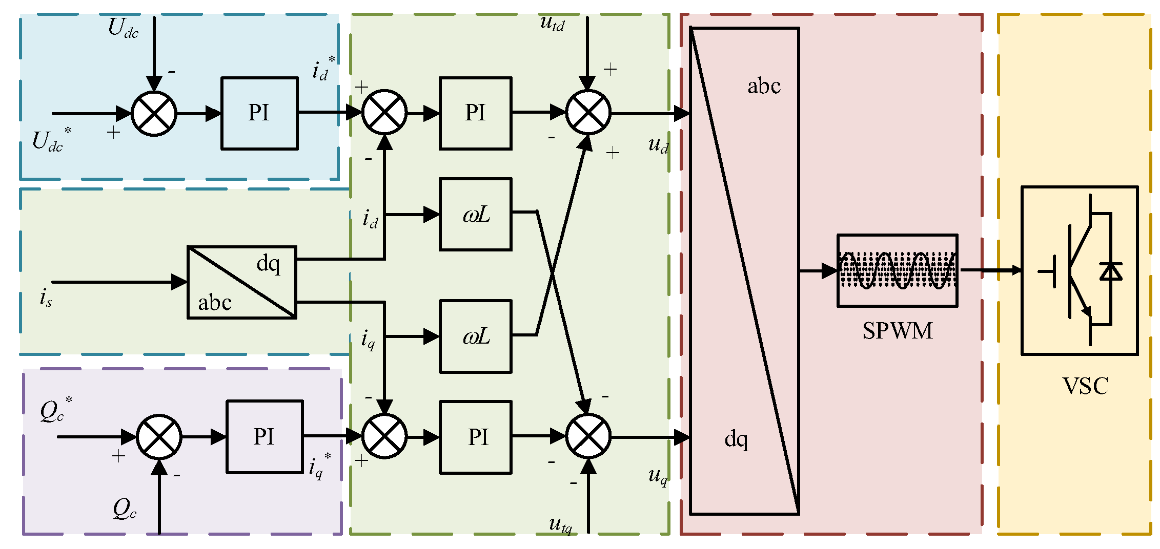
The main circuit of the VSC flexible excitation system for the PSU consists of a VSC and a DC chopper. Therefore, the control strategy for the mid-level layer includes grid-side VSC control and chopper control. The VSC side adopts dual closed-loop decoupling control, and the voltage outer loop is used to stabilize the DC-side voltage, providing active current command values for the current inner loop. The current inner loop controls the waveform and phase of the grid-side current based on the active current command value and the reactive current command value. The control block diagram is shown in Figure 8.

Figure 8.
Grid-side VSC rectifier control block diagram.
As shown in Figure 8, the voltage outer loop within the blue box aims to obtain a stable DC voltage as the control objective, providing active current reference values for the current inner loop. The reactive power outer loop within the purple box provides the reactive current reference value for the current inner loop. The current inner loop in the green box is decoupled and controlled based on the active and reactive current reference values to obtain SPWM control signals for grid-side decoupling control.
Due to the boost capability of the previous stage VSC, even when the terminal voltage drops, it can still maintain the stability of the DC-side voltage. The VSC-type flexible excitation system is equivalent to a chopper with a constant voltage source, and the magnitude of the excitation voltage depends on the duty cycle of the DC chopper. Therefore, the chopper adopts duty cycle control, and the lower device layer adopts SPWM or PWM control.
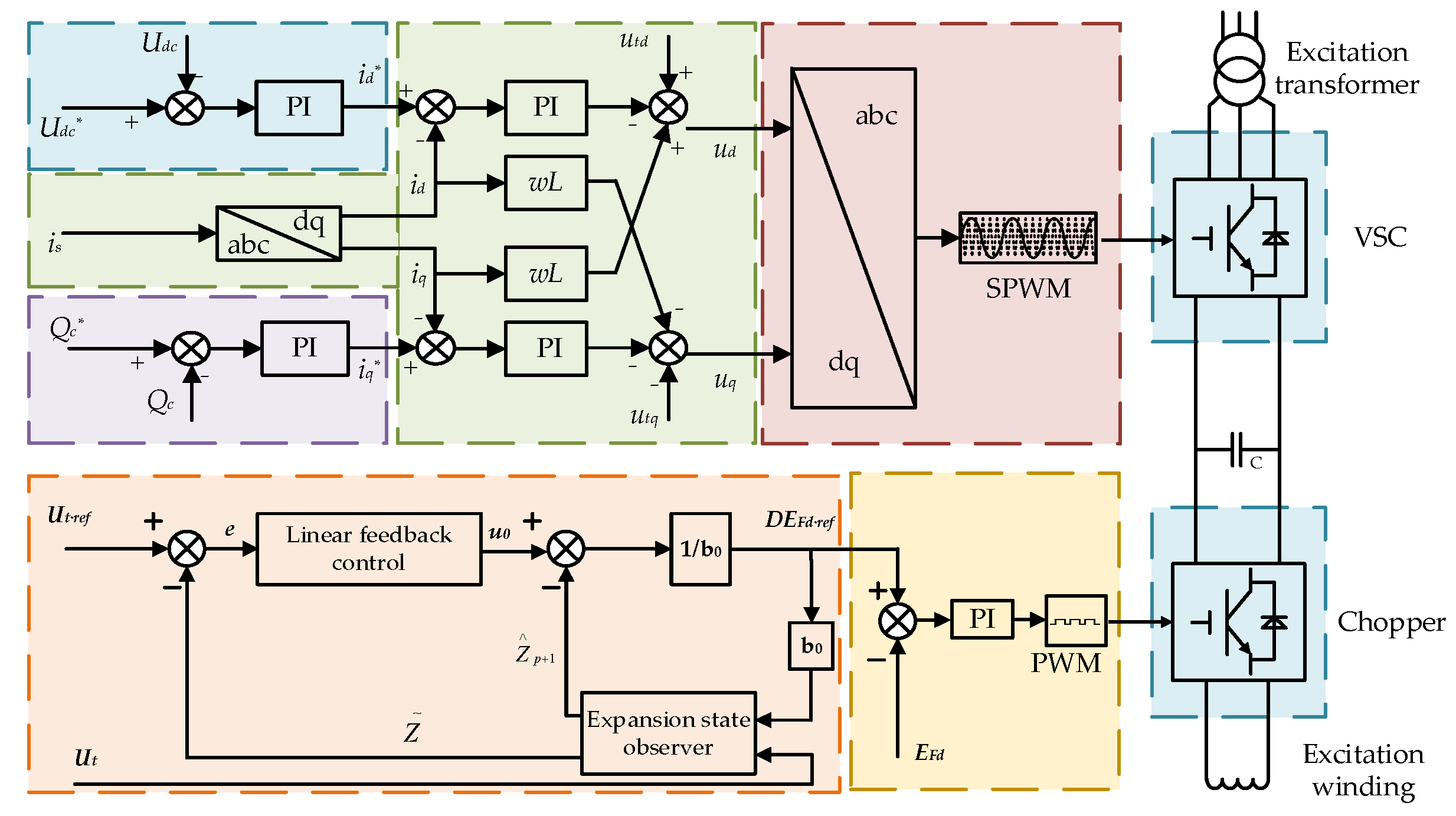
In summary, the overall diagram of linear self-disturbance rejection control for the flexible excitation system of the PSU can be obtained, as shown in Figure 9.

Figure 9.
Overall block diagram of LADRC for pumped storage unit flexible excitation system.
References [22,23,24] analyzed and demonstrated the stability of LADRC, which will not be repeated in this article.
3. LADRC Parameter Tuning Based on Tree Seed Optimizer Algorithm
3.1. Establishing System Performance Indicators
The LADRC controller requires the simultaneous tuning of three parameters: w0, wc, and b0, and therefore the parameter tuning process of LADRC is a three-dimensional trade-off optimization process. Therefore, it is difficult to obtain optimal parameters through conventional trial and error methods, which have strong empirical dependence, are not very friendly, and are not conducive to engineering practice. Therefore, with the help of intelligent algorithms, better parameters can be obtained under certain performance indicators.
To achieve this, it is first necessary to establish system performance indicators. To evaluate the steady-state and transient performance of closed-loop systems, one should consider using the integral of time absolute error (ITAE) metric as defined below:
In the control process, the smaller the ITAE, the better the selected parameters. Based on this principle, the tree seed optimization (TSO) algorithm is used to solve the optimal parameters of LADRC.
3.2. Solution Methods and Processes for TSO Algorithms
The tree seed optimizer algorithm (TSA) is a heuristic algorithm that mimics the propagation between tree clusters and seeds to solve global optimization problems. Its core lies in generating the position of seeds through the tree cluster during the search process. This algorithm has a simple structure and strong selection ability, which is suitable for solving the problem of difficult to adjust LADRC parameters [25]. The specific optimization and tuning steps are shown in Table 1 [26].

Table 1.
The specific optimization and tuning steps.
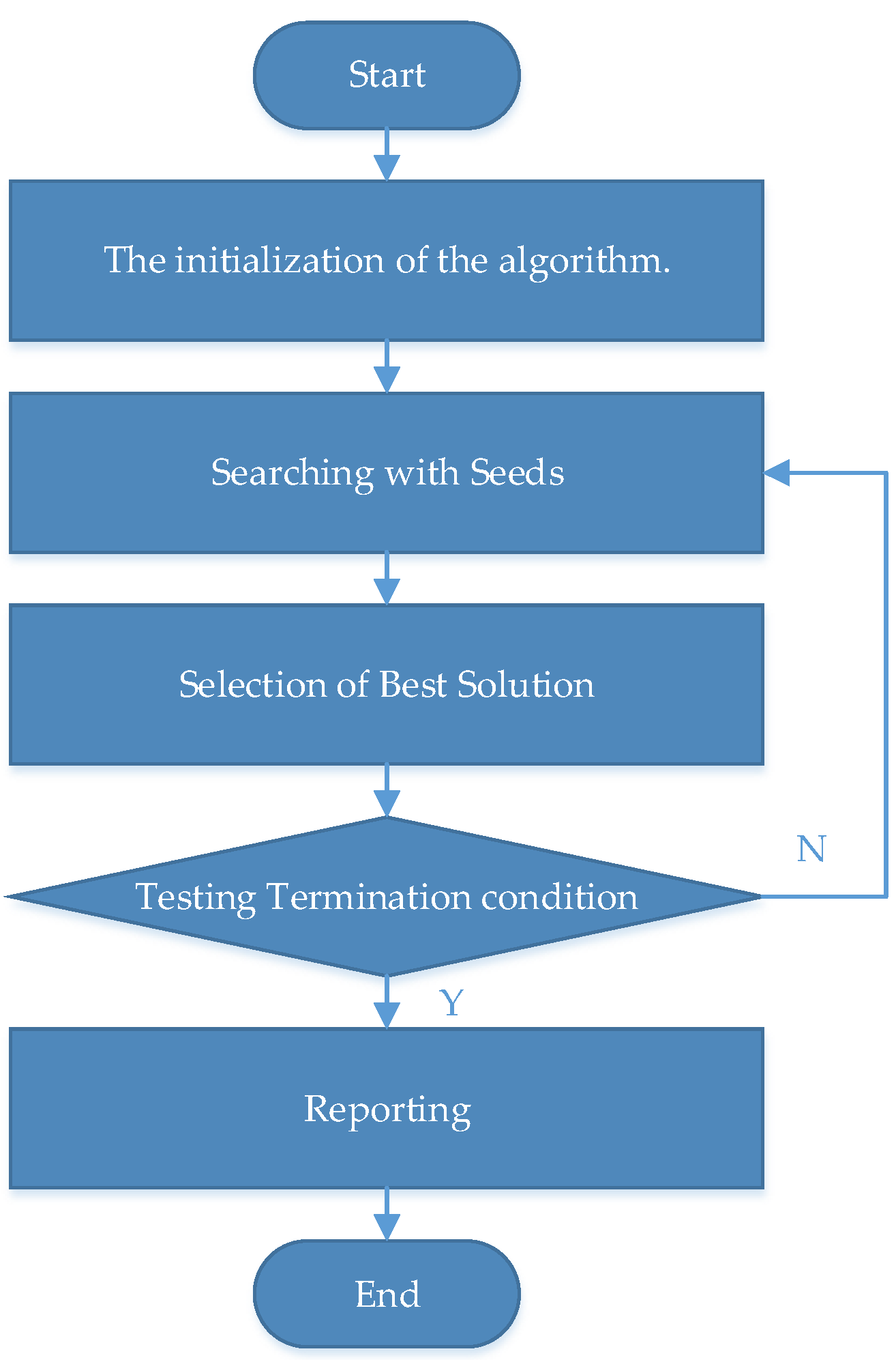
The implementation program flowchart is shown in Figure 10.

Figure 10.
The implementation program flowchart.
4. Simulation Verification
To verify the feasibility and control performance of the flexible excitation system and LADRC strategy proposed in this article, a single-machine infinite bus system of PSU based on the flexible excitation system is built in the platform of MATLAB/Simulink software(2021a). Simulation experiments are conducted to verify the designed flexible excitation system and LADRC under various operating conditions.
The main parameters of the constructed model are shown in Table 2, including synchronous motor, main transformer, excitation transformer, flexible excitation, and infinite bus system. The parameters of the double circuit line are shown in Table 3.
Table 2.
Main parameters of simulation model for PSU based on flexible excitation system.
Table 3.
Double circuit line parameters.
4.1. Simulation of Operating Characteristics of Flexible Excitation System
To verify the performance of the PSU using the flexible excitation system, the simulation of single-phase short-circuit fault and three-phase short-circuit fault on the high-voltage side of the main transformer are simulated under power generation and pumping conditions, and the comparison with the conventional excitation is analyzed.
(1) Simulation of single-phase short-circuit fault on the high-voltage side of the main transformer under generating conditions.
Under generating conditions, a single-phase grounding fault occurs on the high-voltage side of the main transformer, which occurs for 3 s and disappears after 0.1 s. Figure 11 shows the deviation curves of the terminal voltage and rotor speed before and after a short circuit occurs under generating conditions. When the fault occurs, the terminal voltage drops and the power angle begins to oscillate. After the fault disappears, the terminal voltage begins to recover, indicating that the recovery speed of flexible excitation is significantly faster than that of conventional excitation, which can effectively improve the transient stability of the system. From the perspective of power angle oscillation, the oscillation amplitude of flexible excitation is smaller and the convergence speed is also faster. During the fault and recovery period, the flexible excitation system fully utilizes the reactive power exchange capability differently from the conventional excitation system. It can improve the voltage support and oscillation suppression capabilities of the unit by exchanging reactive power with the generator terminal, while the conventional excitation system does not have the ability to exchange reactive power with the generator.
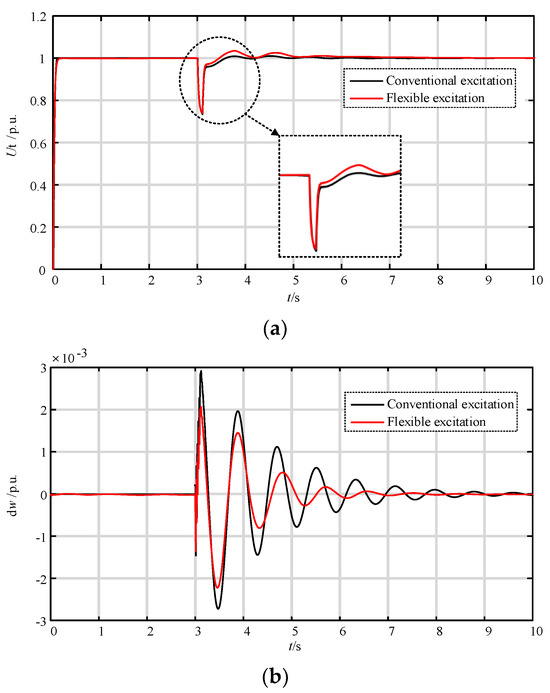

Figure 11.
Simulation diagram of single-phase short-circuit fault on the high-voltage side of the main transformer under generating conditions. (a) Terminal voltage; (b) deviation of rotor speed; (c) generator terminal reactive power exchange.
(2) Simulation of three-phase short-circuit fault on the high-voltage side of the main transformer under generating conditions.
Under generating conditions, a three-phase grounding fault occurs on the high-voltage side of the main transformer, which occurs for 3 s and lasts for 0.1 s. Figure 12 shows the curves of the terminal voltage and deviation of rotor speed before and after a short circuit occurs under generating conditions. The recovery speed of the terminal voltage in flexible excitation is still faster than that in conventional excitation, and the amplitude of rotor speed oscillation is relatively small, with faster convergence speed. Compared to conventional excitation, the number of oscillations is reduced by two times. This is due to the strong excitation ability of the flexible excitation system during faults and recovery, as well as the reactive power exchange with the generator terminal, effectively improving the voltage support and oscillation suppression capabilities of the unit.
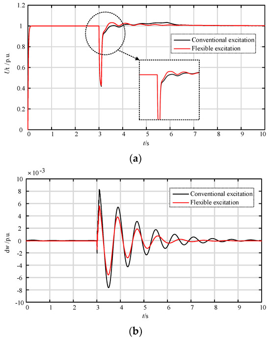
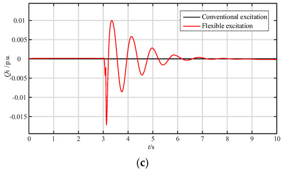
Figure 12.
Simulation diagram of three-phase short-circuit fault on the high-voltage side of the main transformer under generating conditions. (a) Terminal voltage; (b) deviation of rotor speed; (c) generator terminal reactive power exchange.
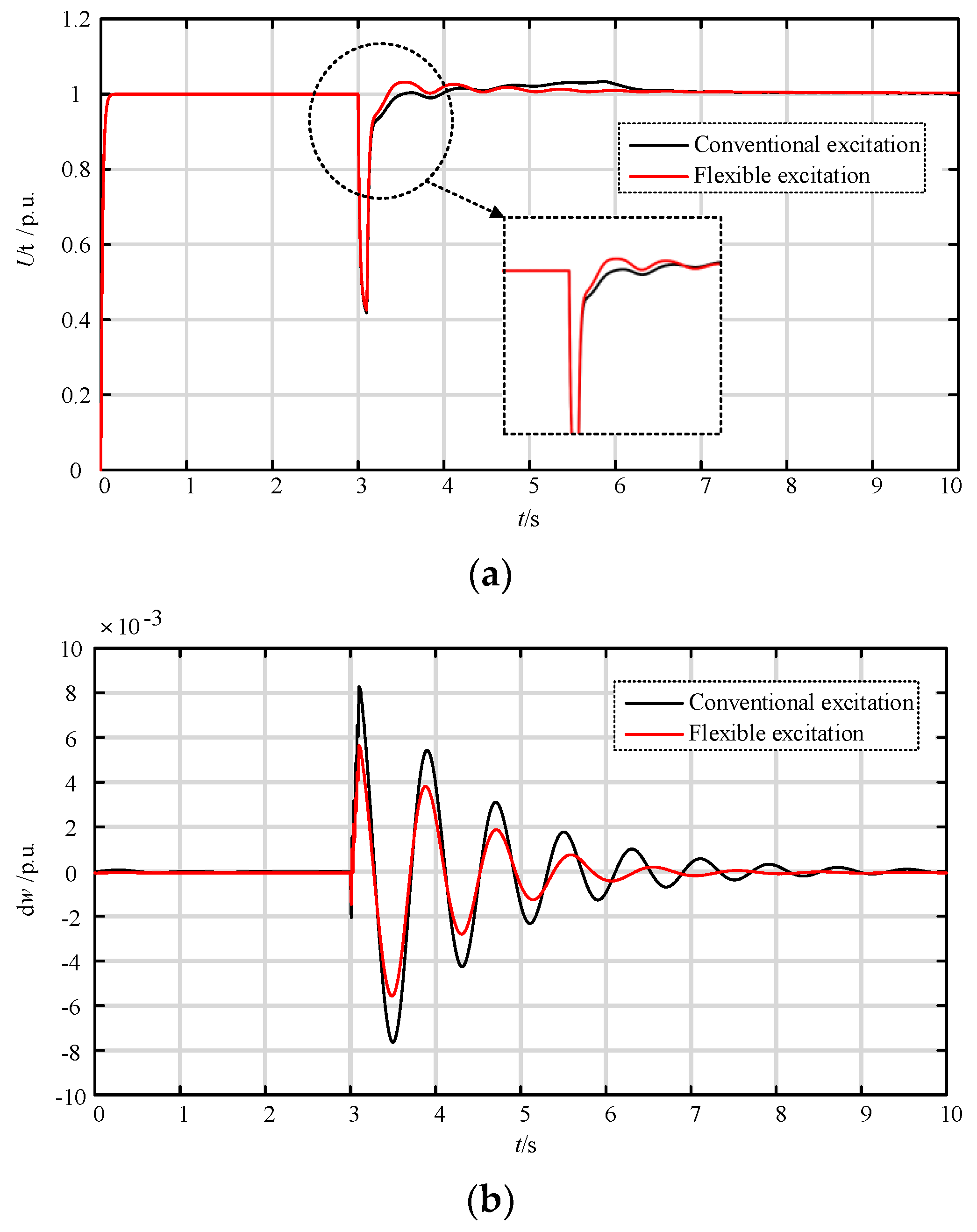
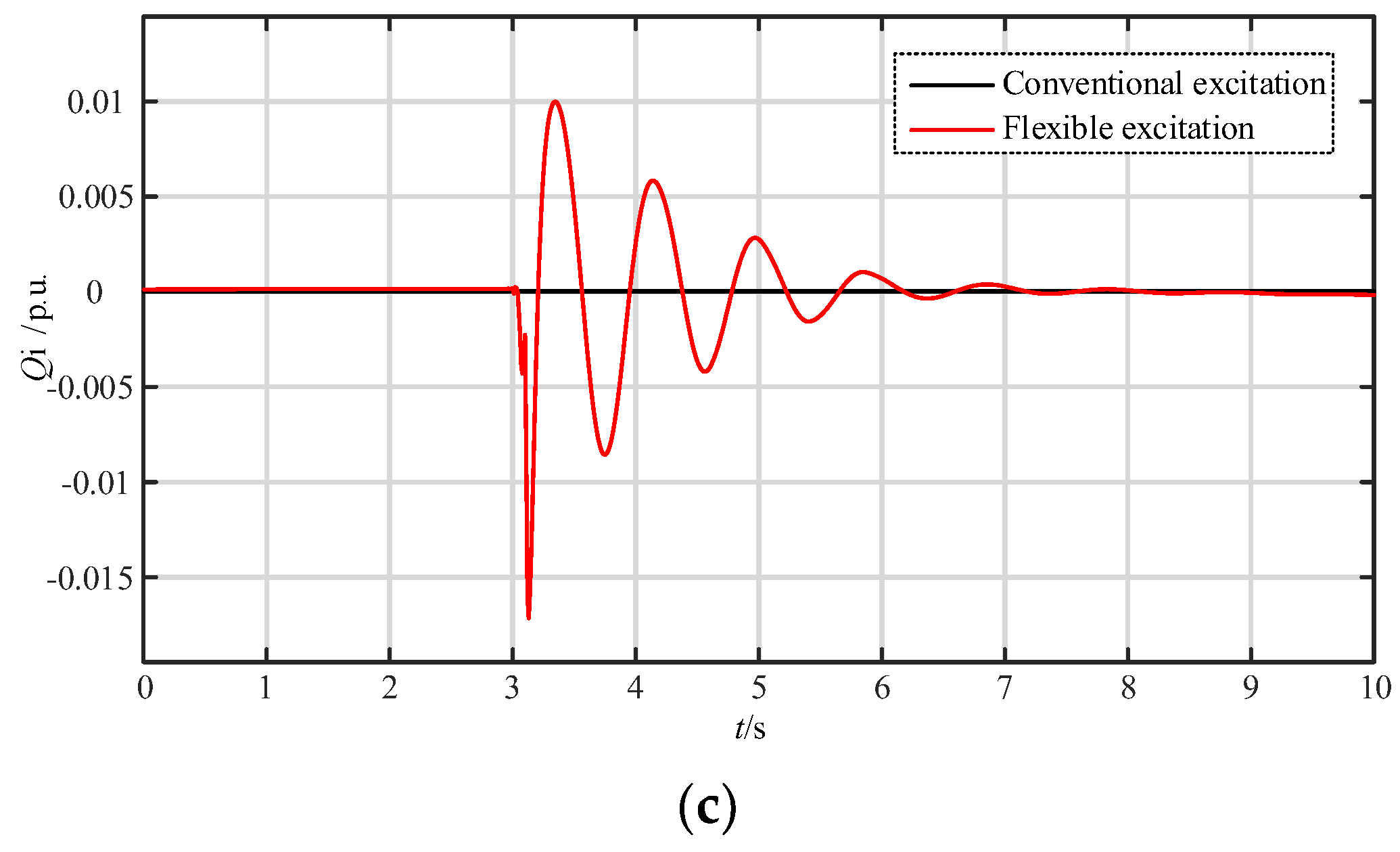
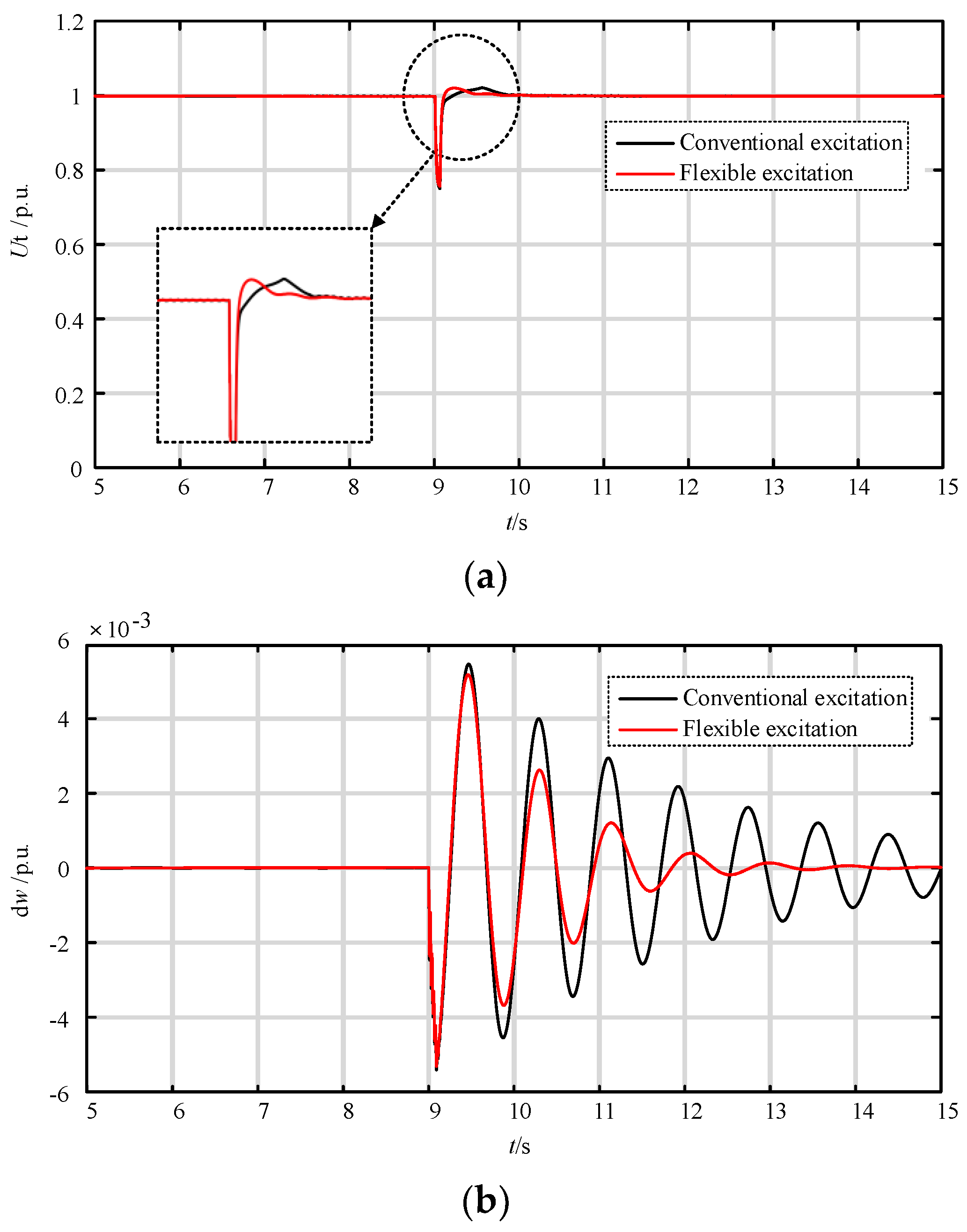
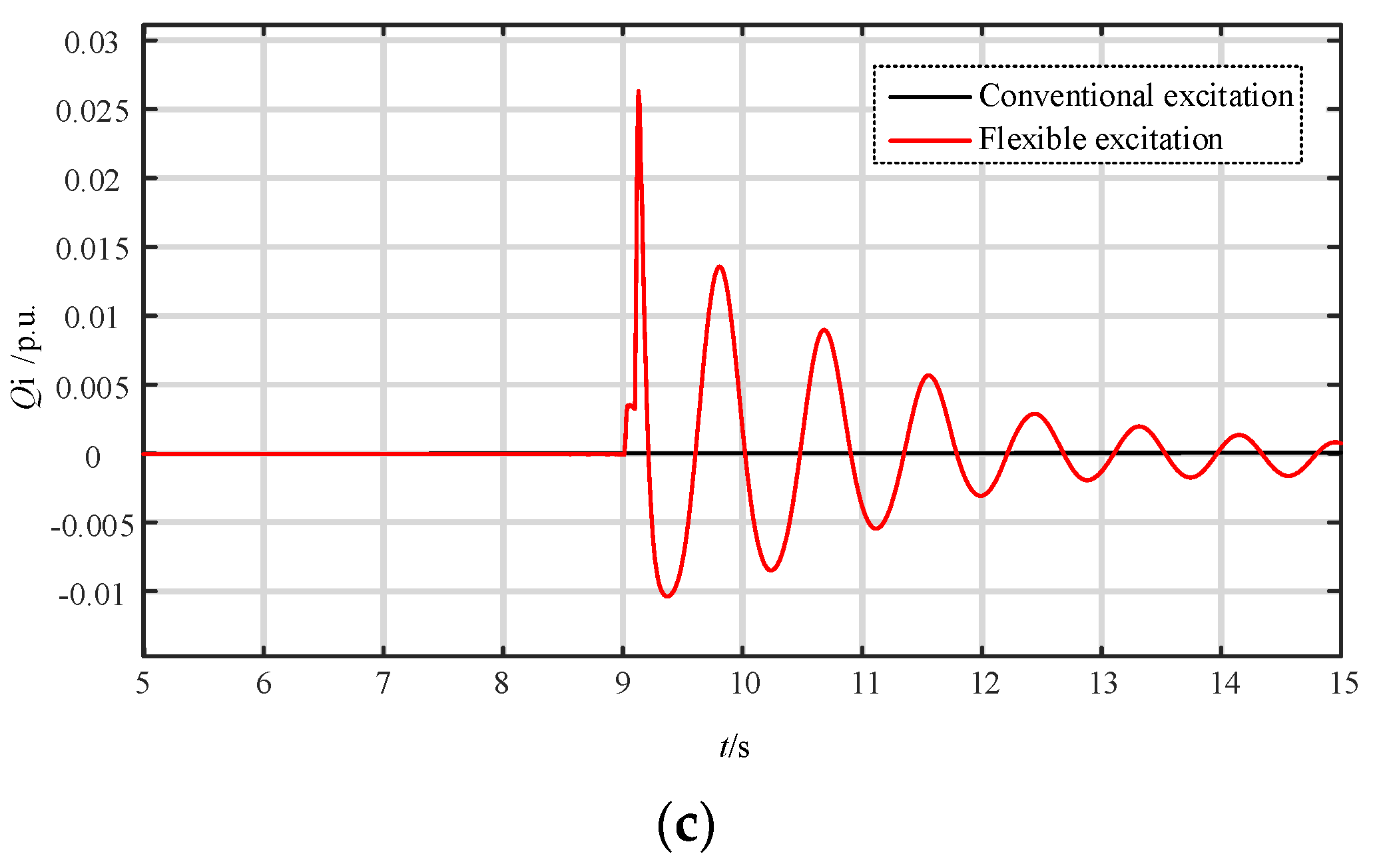
(3) Simulation of single-phase short-circuit fault on the high-voltage side of the main transformer under pumping conditions.
Under pumping conditions, a single-phase grounding fault occurs on the high-voltage side of the main transformer, which occurs for 9 s and lasts for 0.1 s. The simulation results are shown in Figure 13.
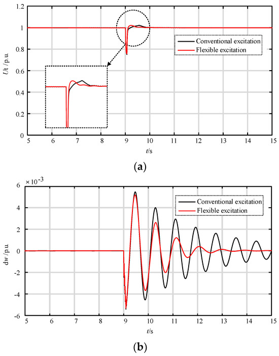
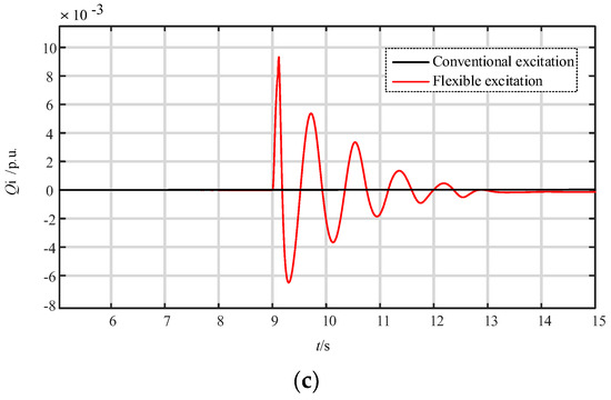
Figure 13.
Simulation diagram of single-phase short-circuit fault on the high-voltage side of the main transformer under pumping conditions. (a) Terminal voltage; (b) deviation of rotor speed; (c) generator terminal reactive power exchange.
It can be seen that after the fault disappears, the terminal voltage begins to recover, and the flexible excitation recovers to a stable value faster. The rotor speed oscillation amplitude is also smaller and the convergence speed is faster. The conventional excitation oscillates seven times, while the flexible excitation oscillates only three times. This fully reflects the reactive power exchange and strong excitation capabilities of flexible excitation systems, which are different from conventional excitation systems, and effectively improves the voltage support and oscillation suppression capabilities of the unit under electric operating conditions.
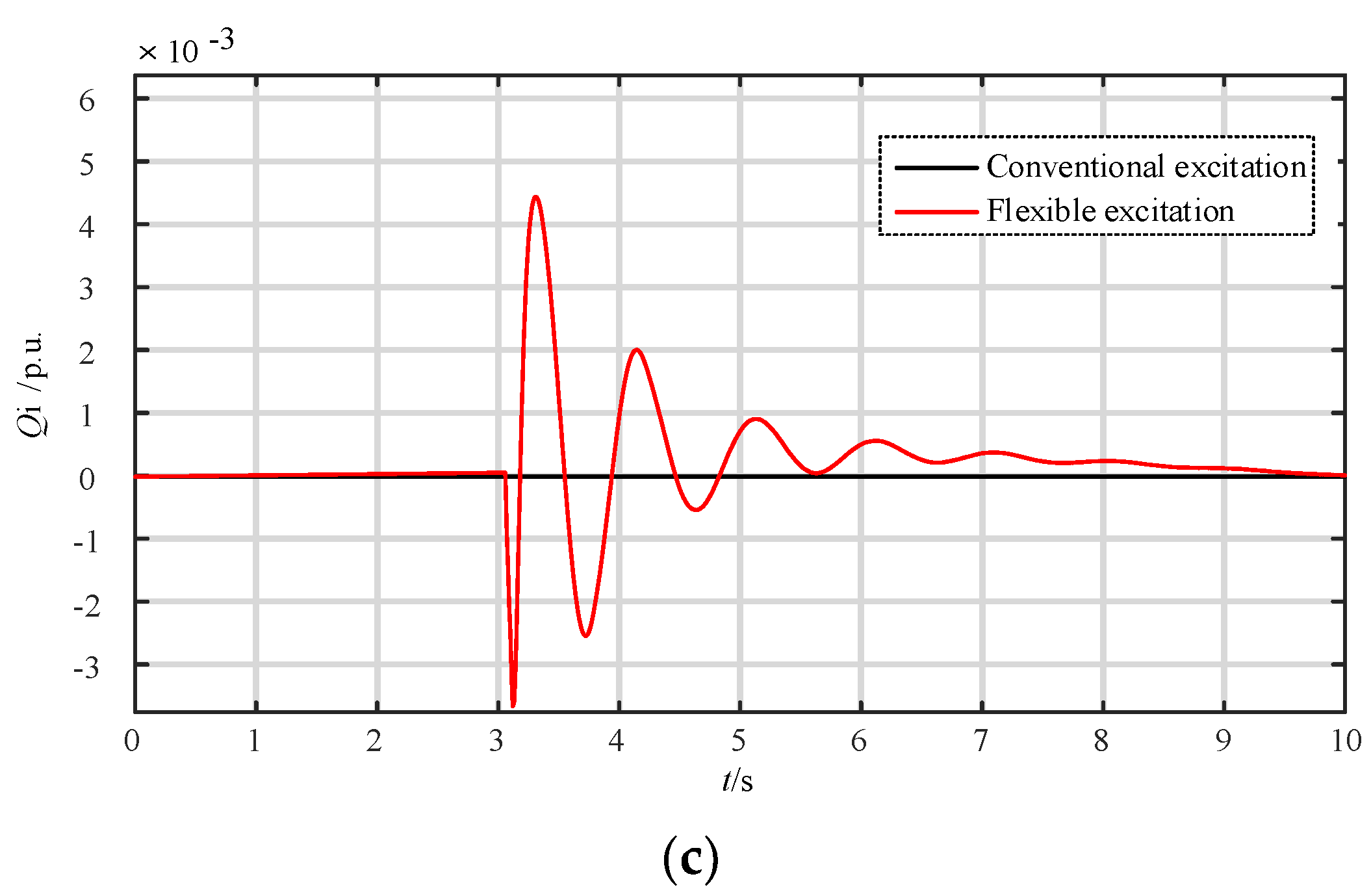
(4) Simulation of three-phase short-circuit fault on the high-voltage side of the main transformer under pumping conditions.
Under pumping conditions, a three-phase grounding fault occurs on the high-voltage side of the main transformer, which occurs for 9 s and lasts for 0.1 s. The simulation results show in Figure 14 indicate that the voltage recovery ability and power angle oscillation suppression ability of flexible excitation are equally excellent under pumping conditions.
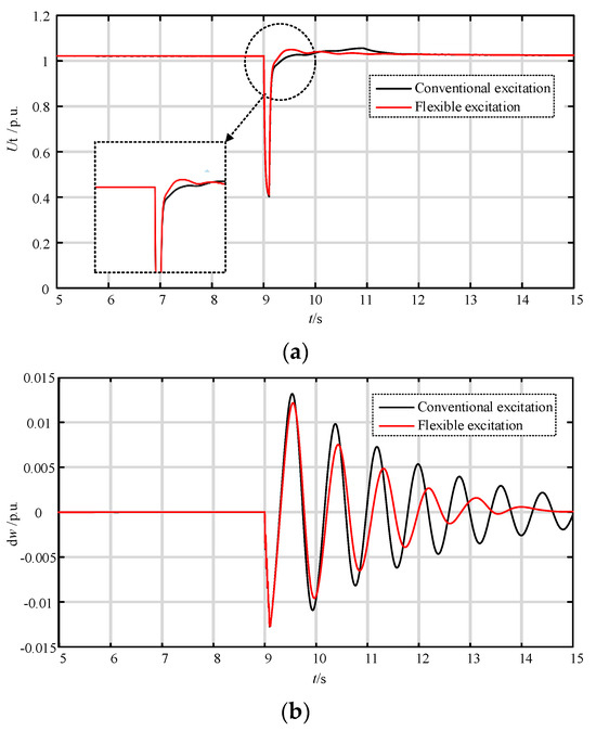

Figure 14.
Simulation diagram of three-phase short-circuit fault on the high-voltage side of the main transformer under pumping conditions. (a) Terminal voltage; (b) deviation of rotor speed; (c) generator terminal reactive power exchange.
4.2. Performance Experiment of Linear Self-Disturbance Rejection Control System
In order to verify the control performance of the proposed LADRC on the flexible excitation system, step response experiments, robustness experiments, and anti-interference experiments are conducted, and the comparison with PID control which is widely used in PSU excitation control is analyzed.
- (1)
- Step response experiment
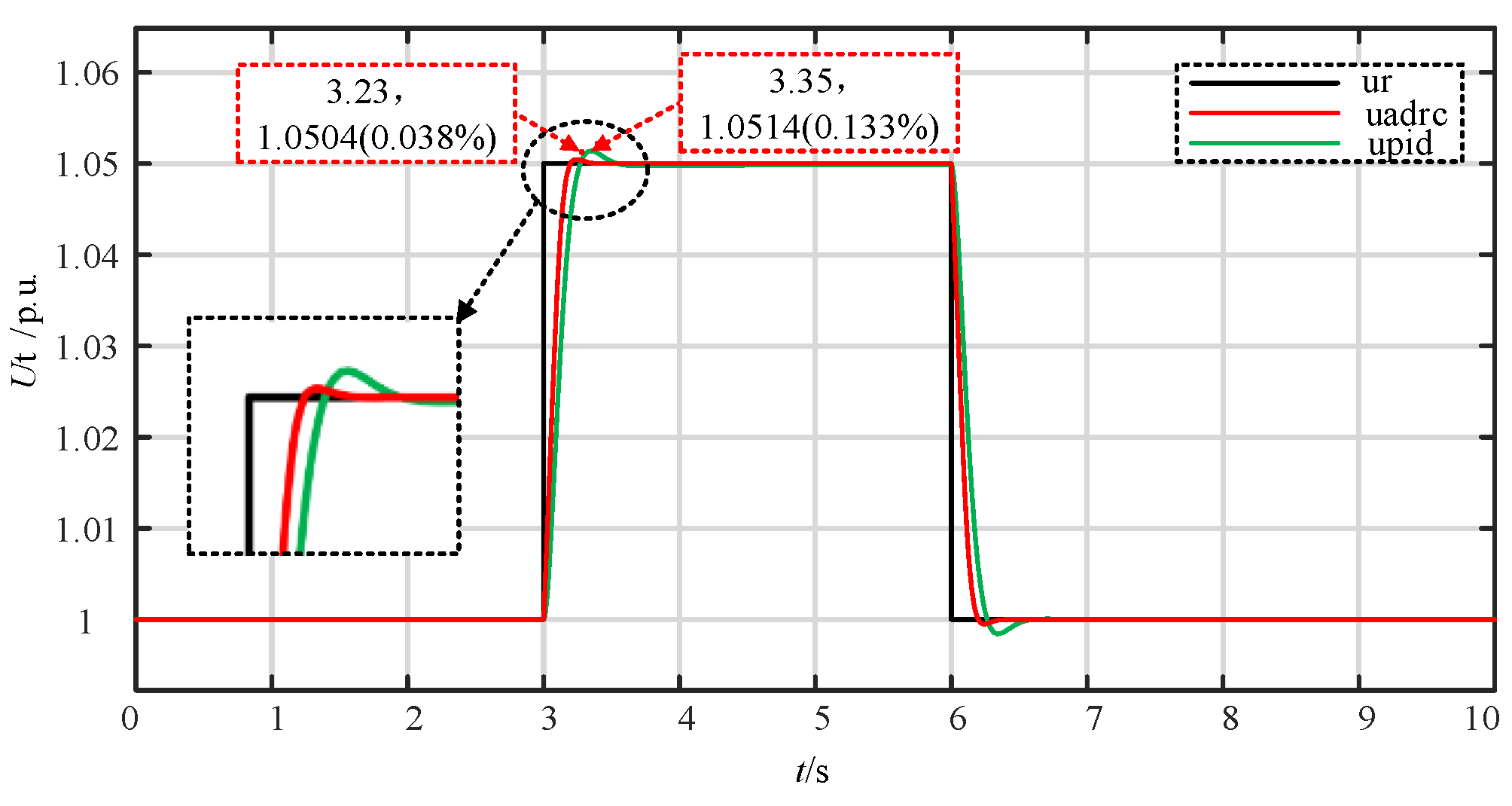
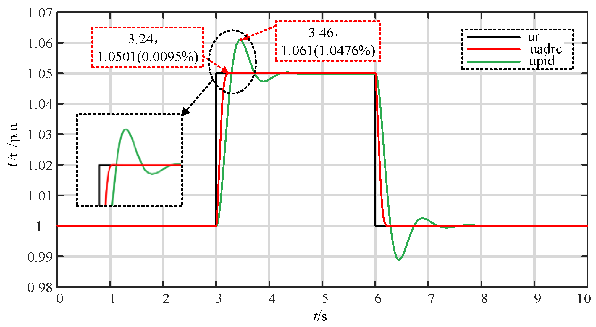
To verify the effectiveness of the proposed controller, ± 5% terminal voltage step response experiments were conducted using PID controller and LADRC controller, respectively. Firstly, the optimal parameters of the PID controller and LADRC controller were obtained through the TSO algorithm. Then, ± 5% of the machine terminal voltage step response experiments were conducted under the optimal parameters, and the simulation results are shown in Figure 15.

Figure 15.
Step response curve of the terminal voltage.
As shown in Figure 15, both the PID controller and the LADRC controller can follow the step command value well. However, compared to the PID controller, the LADRC controller has a faster response speed and smaller overshoot, which verifies that the LADRC controller is better than the PID controller in coordinating the contradiction between response speed and overshoot.
- (2)
- Robustness experiment
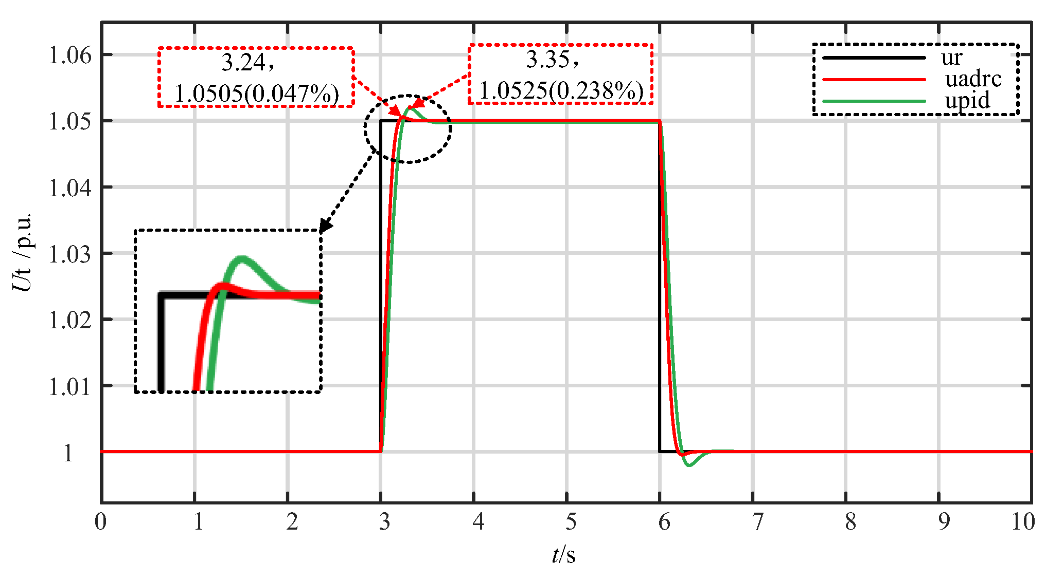
To verify the robustness of the proposed controller, keeping the controller parameters unchanged, the time constant of the generator excitation winding and the excitation system were changed respectively, and a step response was performed. The results are shown in Figure 16 and Figure 17.

Figure 16.
Step response curve after changing the time constant of the generator excitation windings.

Figure 17.
Step response curve after changing the time constant of the excitation system.
It can be seen that after changing the time constant of the generator excitation winding, the step response of the PID controller and LADRC controller shows little change in response time, but the overshoot of the PID controller significantly increases, while the overshoot of the LADRC controller only slightly increases. After changing the time constant of the excitation system, the step response of the PID controller becomes significantly longer, and the overshoot also increases significantly. The response time of the LADRC controller remains almost unchanged, while the overshoot decreases. Both experiments have shown that the robustness of the LADRC controller is superior to that of the PID controller.
- (3)
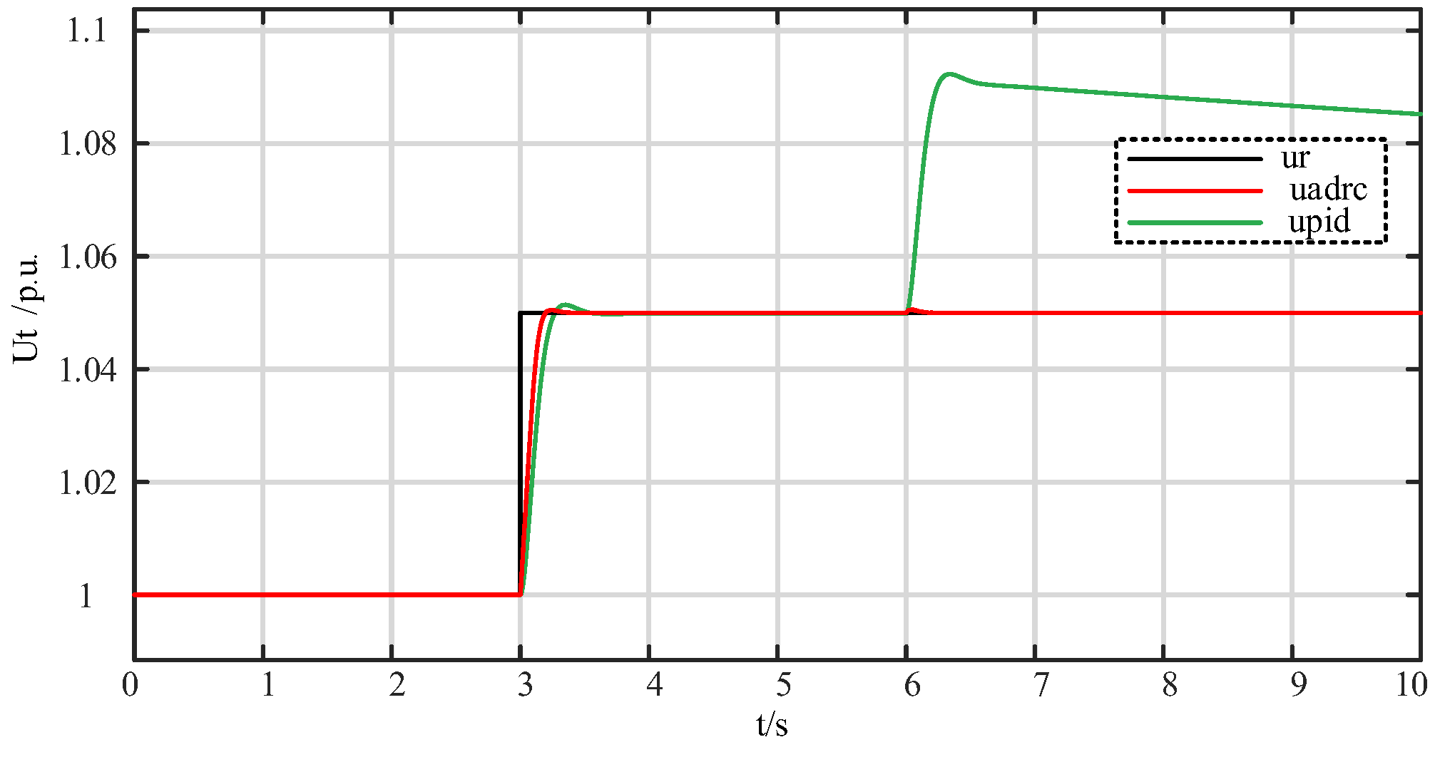
- Anti interference experiment
To verify the anti-interference performance of the proposed controller, a step disturbance was added in front of the control object when the step response reached steady state. The results are shown in Figure 18. It can be seen that with step disturbance, the response of the LADRC controller quickly recovers to stability after slight disturbance, while the PID controller experiences significant deviation after disturbance, and the time to recover to stability significantly increases. It can be seen that the anti-interference performance of the LADRC controller is better than that of the PID controller.

Figure 18.
Step response curve with added step disturbance.
5. Conclusions
This article studies the control system of a pumped storage flexible excitation system based on LADRC. Firstly, a mathematical model of the pumped storage unit based on a flexible excitation system is derived. Secondly, a three-layer control strategy with LADRC as the upper control layer is established, and the controller parameters are intelligently tuned using the TSO algorithm. Finally, the feasibility and superiority of the proposed control strategy are verified through simulation experiments. Through the research in this article, the following conclusions are drawn:
- (1)
- After adopting the flexible excitation system based on fully controlled devices, compared with traditional conventional excitation systems based on thyristors, the voltage support capacity and oscillation suppression ability of PSU are significantly improved;
- (2)
- The flexible excitation system of pumped storage adopts the LADRC controller, which has better performance than the PID controller, can effectively alleviate the contradiction between response speed and overshoot, and has better robustness and anti-interference.
Author Contributions
Conceptualization, B.Z. and J.Z.; methodology, D.W. and J.Z.; software, J.Z.; validation, J.Z., X.C. and S.J.; formal analysis, D.W.; investigation, J.Q. and J.L.; resources, B.Z.; data curation, J.Z.; writing—original draft preparation, J.Z. and X.C.; writing—review and editing, D.W., B.Z. and J.Q.; visualization, J.Z. and S.J.; supervision, D.W.; project administration, B.Z.; funding acquisition, B.Z. and J.Q. All authors have read and agreed to the published version of the manuscript.
Funding
This research was funded by the Science and Technology Project of State Grid Xinyuan Group Co., Ltd., grant number SGXYKJ-2023-048.
Data Availability Statement
The data presented in this study are available on request from the corresponding author.
Conflicts of Interest
The authors declare no conflict of interest. Authors Bo Zhao, Jun Qin and Jiayao Li were employed by the Pumped-Storage Technological & Economic Research Institute State Grid Xinyuan Company Ltd. This study received funding from Science and Technology Project of State Grid Xinyuan Group Co., Ltd. The funder was not involved in the study design, collection, analysis, interpretation of data, the writing of this article or the decision to submit it for publication.
References
- Compiled by State Grid Xinyuan Holdings Co., Ltd. Technology of Pumped Storage Units and Their Auxiliary Equipment; Electric Power Press: Beijing, China, 2019. [Google Scholar]
- National Energy Administration of China. Medium and Long Term Development Plan for Pumped Storage Energy (2021–2035) [EB/OL]. 2021. Available online: https://www.nea.gov.cn/2021-09/09/c_1310177087.htm (accessed on 21 June 2024).
- Lu, J.; Mao, C.; Fan, S.; Wang, D. Microcomputer-Based Excitation Control for Synchronous Generators; Electric Power Press: Beijing, China, 2005. [Google Scholar]
- He, L.; Mao, C.; Lu, J. Novel Excitation System Using High Power Electronics Full Controlled Devices Rectifier. High Volt. Eng. 2009, 35, 1711–1717. [Google Scholar]
- Wu, J.; He, L.; Mao, C.; Lu, J.; Wang, D. Novel excitation system for synchronous generators. J. Electr. Power Sci. Technol. 2009, 24, 12–18. [Google Scholar]
- He, J.; Mao, C.; Lu, J.; Wang, D.; Yang, J. Control Strategy of Voltage Source Converter Excitation System Based on Full Controlled Device. Trans. China Electrotech. Soc. 2012, 27, 240–247+263. [Google Scholar]
- Peng, Y.; Zhang, J.; Mao, C.; Xiong, H.; Zhang, T.; Wang, D. A Coordinated Optimal Strategy for Voltage and Reactive Power Control with Adaptive Amplitude Limiter Based on Flexible Excitation System. Energies 2021, 14, 5212. [Google Scholar] [CrossRef]
- Wu, K.; Zhang, J.; Wu, L. Novel Flexible Excitation System Based on Multilevel Topology Technology. Electr. Power 2019, 52, 100–106. [Google Scholar]
- Mao, C.; He, J.; Wang, D.; Lu, J. Multivariable Feedback Linearization Scheme for New Excitation Systems Based on Full Controlled Devices. Proc. CSEE 2013, 33, 53–60+10. [Google Scholar]
- Wu, K.; Zhang, T.; Zhang, J.; Yu, M.; Mao, C.; Xion, H.; Wang, D. Optimum design method of flexible excitation system for improving damping of low frequency oscillation. Electr. Mach. Control. 2020, 24, 105–114. [Google Scholar]
- Zhang, T.; Cheng, L.; He, S.; Yu, M.; Mao, C.; Wang, D.; Zhang, J.; Han, B.; Tao, Z. Optimal Design Method of Flexible Excitation System for Improving Power System Stability. IEEE Trans. Ind. Appl. 2021, 57, 2120–2128. [Google Scholar] [CrossRef]
- Wang, L.; Zhang, J.; Wang, B.; Zhuo, G.; Hua, W.; Xiong, H. Research on the improvement of transient stability characteristics of the receiving end power grid by flexible excitation. Zhejiang Electr. Power 2022, 41, 72–77. [Google Scholar]
- Zhang, T.; Mao, C.; Zhang, J.; Tian, J.; Yu, M.; Wu, K.; Xiong, H.; Wu, L.; Yu, H. Design and Field Application of Flexible Excitation System Damping Controllers. IEEE Trans. Ind. Electron. 2021, 68, 949–959. [Google Scholar] [CrossRef]
- Han, J. Active Disturbance Rejection Controller and Its Application. Control. Decis. 1998, 13, 19–23. [Google Scholar]
- Gao, Z. Active disturbance rejection control: A parallel shift in feedback control system design. In Proceedings of the 2006 American Control Conference, Minneapolis, MN, USA, 14–16 June 2006; pp. 2399–2405. [Google Scholar]
- Cheng, L. Optimization Control Strategy for Excitation System of Energy Storage Type Fully Controlled Device. Master’s Thesis, Huazhong University of Science and Technology, Wuhan, China, 2023. [Google Scholar]
- Yu, M. Analysis of Operating Characteristics of Flexible Excitation System. Master’s Thesis, Huazhong University of Science and Technology, Wuhan, China, 2022. [Google Scholar]
- Zhang, T. Damping Control Method and Field Application of Flexible Excitation System. Ph.D. Thesis, Huazhong University of Science and Technology, Wuhan, China, 2023. [Google Scholar]
- Wu, L.; Mou, W.; Shi, Y.; Han, B. Research and Application of PSS for Pump Working Condition of Large Pumping and Storage Power Station Unit. Hydroelectr. Pumped Storage 2022, 8, 40–44. [Google Scholar]
- Liu, Q. Power System Stability and Generator Excitation Control; Electric Power Press: Beijing, China, 2007. [Google Scholar]
- Gao, Z. Scaling and bandwidth-parameterization based controller tuning. In Proceedings of the 2003 American Control Conference, Denver, CO, USA, 4–6 June 2003; pp. 4989–4996. [Google Scholar]
- Zheng, Q.; Gao, L.D.; Gao, Z. On stability analysis of active disturbance rejection control for nonlinear time-varying plants with unknown dynamics. In Proceedings of the 46th IEEE Conference on Decision and Control, New Orleans, LA, USA, 12–14 December 2007; pp. 3501–3506. [Google Scholar]
- Chen, Z.; Sun, M.; Yang, R. Onthe stability of linear active disturbance rejection control. Acta Autom. Sin. 2013, 39, 574–580. [Google Scholar] [CrossRef]
- Tian, G.; Gao, Z. Frequency response analysis of active disturbance rejection based control system. In Proceedings of the 2007 IEEE International Conference on Control Applications, Singapore, 1–3 October 2007; pp. 1595–1599. [Google Scholar]
- Köse, E. Optimal Control of AVR System With Tree Seed Algorithm-Based PID Controller. IEEE Access 2020, 8, 89457–89467. [Google Scholar] [CrossRef]
- Kiran, M.S. TSA: Tree-seed algorithm for continuous optimization. Expert Syst. Appl. 2015, 42, 6686–6698. [Google Scholar] [CrossRef]


Disclaimer/Publisher’s Note: The statements, opinions and data contained in all publications are solely those of the individual author(s) and contributor(s) and not of MDPI and/or the editor(s). MDPI and/or the editor(s) disclaim responsibility for any injury to people or property resulting from any ideas, methods, instructions or products referred to in the content. |
© 2024 by the authors. Licensee MDPI, Basel, Switzerland. This article is an open access article distributed under the terms and conditions of the Creative Commons Attribution (CC BY) license (https://creativecommons.org/licenses/by/4.0/).