Abstract
Natural gas hydrate (NGH) trials have been performed successfully with different development methods and gas recovery drainage technologies. Multiphase flow in a wellbore and the drainage of natural gas hydrate are two important parts for its whole extraction process. Additionally, the choice of the drainage method is linked to the development method, making the drainage of NGH more complex. Jet pump drainage is usable for NGH production wells with the combined depressurization and thermal stimulation method. The objective of this study is to shed more light on the multiphase flow behavior in jet pump drainage and NGH production wells and put forward suggestions for adjusting heat injection parameters. The mechanism of jet pump drainage recovery technology for NGH wells was analyzed and its applicability to NGH development by the combined depressurization and thermal stimulation method was demonstrated. In addition, multiphase flow models of tubing and annulus were established, respectively, for the phenomenon of the countercurrent flow of heat exchange in the process of jet pump drainage and gas production, and the corresponding multiphase flow laws were derived. On the basis of these studies, sensitivity analysis and the optimization of thermal stimulation parameters were conducted. It is demonstrated that jet pump drainage gas recovery technology is feasible for the development of onshore NGH with the combined depressurization and thermal stimulation method. The laws of multiphase flow in the tubing and annulus of jet pump drainage and NGH production wells were disclosed in this study. Numerical simulation results show that the temperature and pressure profiles along the wellbore of jet pump drainage and NGH production wells during the drainage recovery process are affected by injection conditions. Increasing injection rate and injection temperature can both improve the effect of heat injection and reduce the hydrate reformation risk in the bottom of the annulus. This study offers a theoretical basis and technical support for production optimization and hydrate prevention and control in the wellbore of jet pump drainage and NGH production wells.
1. Introduction
Known as “combustible ice”, NGH has the potential to provide a new source of clean and abundant energy, but there are still many challenges and technical difficulties in its exploitation and production. Depressurization technology has been proved as an economical and effective method for the production trials of an NGH reservoir, such as two offshore tests in Nankai Trough in Japan [1,2], two production trials in the Shenhu area in China [3,4] and others. Nonetheless, integrating depressurization with thermal stimulation emerges as a more promising strategy compared to solely employing either approach [5].
Up to now, several studies on fluid dynamics in NGH wells have been conducted, mainly focusing on flow assurance in deepwater drilling and electric submersible pump (ESP)-lifted gas drainage recovery, etc. J. Petersen launched a dynamic kick simulator to analyze the flow behavior of a drilling well and the possibility of hydrate formation during well control operations [6]. Fu et al. established mathematical models to analyze multiphase behavior and factors affecting the hydrate generation region in the deep water drilling process [7]. Wang et al. investigated the hydrate generation region and analyzed its influencing factors on annulus fluid flow characteristics during the same process [8]. Bassani et al. introduced the effects of the deposition of a hydrate layer of constant thickness on the pipe wall in a two-phase gas–liquid mechanistic slug flow model [9]. Wei et al. applied numerical calculation methods to acquire the non-equilibrium multiphase flow laws of marine NGH reservoirs by solid fluidization development [10]. ESP drainage gas recovery technology is mostly employed in NGH reservoirs with depressurization [1,2]. Sukru et al. developed a simulator to predict gas hydrate formation risks along a wellbore during the process of gas production from methane hydrates through an ESP production string [11]. Liu et al. established a gas–liquid flow model in an offshore NGH production system, considering the coupling of the wellbore, the formation and the ESP [12]. Ping et al.’s research sought to predict multiphase characteristics and assessed the risk of NGH regeneration in ESP-lifted NGH production wells [13].
However, little research has been reported to investigate the feasibility and flow dynamics of the fluid in jet pump drainage and NGH production wells using the combined depressurization and thermal stimulation method. There are many challenges to the drainage and extraction of a hydrate, such as low BHP, a high GLR, the presence of a hydrate, etc. [14]. Jet pump drainage and gas production technology is more feasible for complex fluids, such as those with a high GLR and high sand content, than an ESP and deserves more consideration than other drainage methods to unload hydrate wells [14,15]. This technology was used in a CO2-CH4 displacement experiment in Alaska North Slope [16]. Multiphase behavior in jet pump drainage and NGH production wells is the basis for the design of drainage and the optimization of heat injection parameters. Understanding the multiphase behavior of jet pump drainage and NGH production wells can significantly enhance their thermal stimulation efficiency. Therefore, it is necessary to study multiphase flow in jet pump drainage and NGH production wells.
In this paper, the feasibility and mechanism of jet pump drainage gas recovery technology for NGH development using the combined depressurization and thermal stimulation method were investigated. The multiphase flow dynamics of jet pump drainage and gas production wells were described in detail by mathematical modeling. In addition, the thermal stimulation parameters of jet pump drainage and NGH production wells were optimized. This study can provide valuable guidance for optimizing production and assessing the risk of hydrate regeneration of jet pump drainage and NGH production wells, as well as suggestions for hydrate prevention strategies.
2. Feasibility Analysis and Mechanism Study of Jet-Pump-Lifted NGH Wells
2.1. Feasibility Analysis
The combined depressurization and thermal stimulation technique beautifully blends the strengths of the individual depressurization and thermal stimulation approaches. It is remarkably more effective compared to a solo method like depressurization and can compensate for the energy utilization of the depressurization method [17]. Given the substantial energy consumption associated with heat loss when utilizing thermal stimulation in sea water wells, this combined approach appears ideal for offshore NGH extraction in marine areas [5].
A jet pump, which is a unique hydraulic device, uses the momentum exchange between power and formation fluid for smooth liquid flow without any moving parts. It is feasible for a wide range of displacement operations and applicable to a high GOR, high sand and other complex fluids, meeting the requirements of the drainage gas recovery of flooded gas wells. In addition, chemicals such as glycol can be added to jet pumps as a power fluid, inhibiting hydrate formation [14]. The sand resistance of a jet pump is higher than that of an ESP. At the same time, it can also avoid the problem of underloading stops of the pump caused by an insufficient liquid supply. When the well condition changes, the size of the throat and nozzle can be adjusted, and the operating cost is lower than that of an ESP [15]. Therefore, jet pump drainage gas recovery technology is more feasible than an ESP for the development of offshore NGH using the combined depressurization and thermal stimulation method.
2.2. Mechanism Study
As shown in Figure 1, the ground plunger pump is applied to increase the high pressure of the power fluid and pressurized hot water is injected from the tubing into the well to drive the downhole jet pump to perform drainage gas recovery. As for jet pump drainage and NGH production wells with the combined depressurization and thermal stimulation method, hot water injected from the tubing can be used as the high-pressurized power fluid for energy conversion between natural gas and water extracted from the reservoir. Natural gas and water are discharged to the surface together with the hot power fluid, which increases the temperature of the annulus fluid and greatly reduces the risk of hydrate regeneration in the annulus.
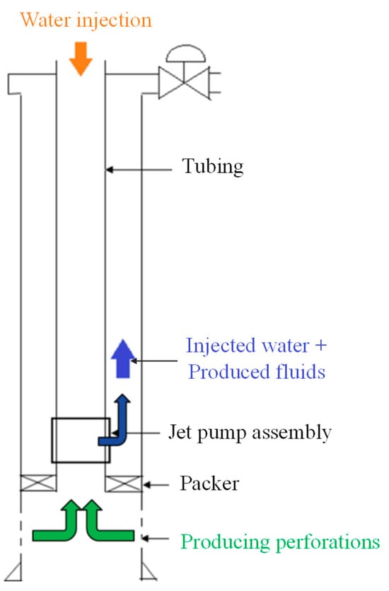
Figure 1.
Schematic of the jet-pump-lifted NGH production system using combined depressurization and thermal stimulation method.
When the jet pump operates, the speed of high-pressurized power fluids is accelerated considerably through the nozzle, inducing a dip in the suction chamber’s pressure, as shown in Figure 2. Simultaneously, natural gas and water extracted from the hydrate reservoir are quickly drawn into the suction chamber inside the pump throat. After the injected high-pressurized power fluid and low-pressurized water and natural gas at the bottom of the well are combined in the throat, the mutual transfer of energy and mass takes place. Within the diffuser, the velocity and pressure of the blended fluid augment, propelling it upwards through the annulus [18].
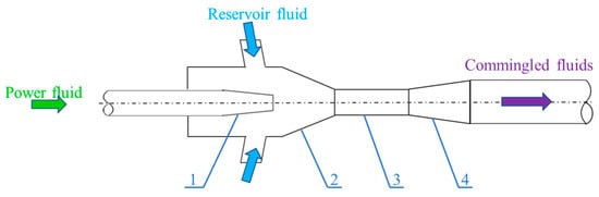
Figure 2.
Schematic diagram of jet pump:1—nozzle, 2—suction chamber, 3—throat, 4—diffuser.
3. Model Establishment and Solution
3.1. Establishment of Wellbore Flow Model of Jet-Pump-Lifted NGH Wells
Standard circulation is one of the jet pump configurations, which means that power fluid is pumped down through the tubing string and produced fluid is returned through the annulus [19]. For the standard circulating jet pump drainage and NGH production well, hot water is injected from the head of the tubing at the surface and passes through the jet pump nozzle into the annulus during the hydrate development process with the depressurization and thermal stimulation method. It is commingled with natural gas and water extracted from the hydrate reservoir in the annulus and then delivered to the surface. A flow schematic of the gas hydrate production system using the combined depressurization and thermal stimulation method is presented in Figure 3. Multiphase flow models of the tubing and annulus can be established, respectively, for the phenomenon of the countercurrent flow of heat exchange in the process of jet pump drainage and gas production based on the flow process of jet-pump-lifted NGH wells.
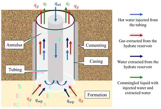
Figure 3.
Countercurrent flow schematic of NGH production system by combined depressurization and thermal stimulation method.
3.1.1. Continuity Equation
Based on the principle of mass conservation, the continuity equation for the fluid injected from the tubing can be expressed in Equation (1).
The continuity equation of the two-phase flow with the gas phase and the liquid phase in the annulus can be described in Equations (2) and (3).
3.1.2. Momentum Conservation Equation
The fluid flow in the jet pump drainage and NGH production well is mainly influenced by gravity, friction and a change in acceleration. According to the principle of the conservation of momentum, the wellbore pressure distribution model for a hot water injection well can be expressed in Equation (4):
Similarly, the pressure distribution model for the gas–liquid two-phase flowing in the annulus can be obtained:
3.1.3. Energy Conservation Equation
It is assumed that the heat transfer is unsteady for the formation and steady for the tubing and annulus. In the process of jet pump drainage gas recovery, there is a phenomenon of the countercurrent flow of heat exchange between the hot water injected through the tubing and the commingled fluid in the annulus. The temperature of fluid in the flow process reaches thermal equilibrium with the temperature of the strings, cement and formation [20]. A heat balance diagram for the strings and formation is shown in Figure 4.
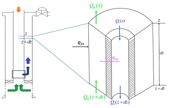
Figure 4.
Diagram of the heat balance for strings and formation.
The heat balance relationship between the single-phase flow of hot water in the tubing and the gas–liquid two-phase flow in the annulus can be described as follows:
Heat amount transfers from the annulus to tubing can be given by
where
The rate of heat transfer between the formation and the annulus is as follows:
where
3.2. Model Solution
3.2.1. Boundary Conditions
The fluid parameters at the wellhead of the tubing can be monitored, so the boundary condition for the tubing can be given as follows:
Similarly, the boundary condition for the annulus can be given as follows:
At the bottom of the jet pump well, the injected fluid is mixed with the extracted fluid from the hydrate reservoir. The Hasan–Kabir–model was used to calculate the temperature at the bottom of the annulus [15].
3.2.2. Methodology
The tubing fluid temperature model can be given by
where
The general solution for Equation (17) is as follows:
The solution for the annulus fluid temperature model can be expressed by
The coefficients in Equations (19) and (20) can be expressed in the following:
3.2.3. Solution Process
The multiphase flow models of the tubing and annulus were constructed for the phenomenon of the countercurrent flow of heat exchange in jet pump drainage and gas production well with the Hasan–Kabir–model [15] in this study. The flowchart for calculating wellbore countercurrent heat transfer models is shown in Figure 5.
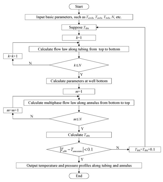
Figure 5.
Flowchart for calculating wellbore countercurrent heat transfer models.
3.2.4. Model Validation
Up to now, no hydrate production test has been conducted with jet pump drainage and gas production technology. Fortunately, the physical process and heat transfer in the case in which heavy oil is produced by adding light oil are similar to this NGH production well extracted with the method of depressurization and hot water injection. Therefore, the proposed models can be validated using the case of a heavy oil well with the injection of light oil diluent in the Tahe oil field in China. The basic parameters for model validation are presented in Table 1.

Table 1.
Basic parameters for model validation.
As shown in Figure 6, the calculated temperature profile matches well with the measured data. After model validation, sensitivity analysis and parameter optimization can be conducted based on the proposed models.
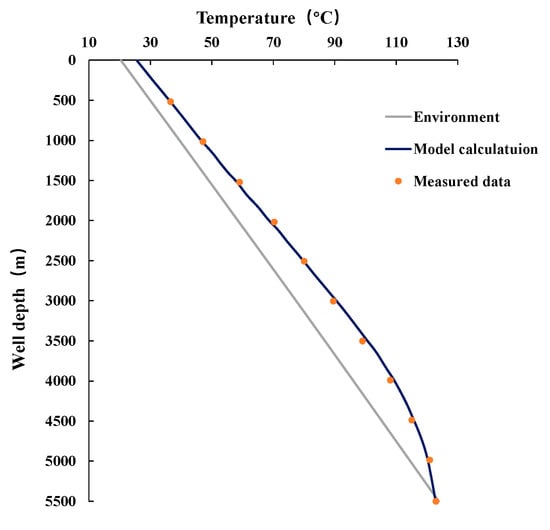
Figure 6.
Comparison of predicted temperature profile by model with measured data.
4. Results and Discussion
4.1. Basic Parameters for Simulations
The basic parameters of the NGH reservoir and jet pump drainage and gas production well are collected from the Mallik permafrost site in Canada [21], as presented in Table 2.
Table 2.
Basic parameters for simulations.
4.2. Analysis of Multiphase Flow Behavior in Jet Pump Drainage and NGH Production Wells
The multiphase flow behavior of the fluid in jet pump drainage and NGH production wells can be described by solving the multiphase flow models of the tubing and annulus for the countercurrent heat transfer process.
4.2.1. Temperature Profiles of Tubing and Annulus
The temperature distribution in the annulus is significantly more influenced by the tubing temperature than by the formation temperature since the overall heat transfer resistance between the tubing and the annulus fluid is much lower than that between the annulus fluid and the formation. The temperature distribution trends between the annulus and tubing in the jet pump drainage and NGH production wells with hot water as the power fluid are consistent, and the farther down the well bottom, the smaller the temperature difference, as displayed in Figure 7. The reason for this phenomenon is that the annulus fluid gains more heat from the tubing fluid than it loses to the surrounding area, and this difference in heat increases rapidly as the fluid in the annulus approaches the wellhead. The sudden change in the temperature profile at the bottom of the annulus in Figure 7 is caused by mixing natural gas and water from the gas hydrate reservoir with hot water injected from the tubing, making the derivative of the fluid temperature at the bottom of the annulus not zero [15].
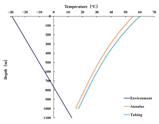
Figure 7.
Temperature distributions along the wellbore.
4.2.2. Pressure Profiles in Tubing and Annulus
As shown in Figure 8, the pressure gradient of the annulus is smaller than that of the tubing, which is mainly caused by the decrease in fluid density in the annulus after gas from natural hydrate decomposition enters the annulus. When natural gas and water flow through the jet pump, there is a significant change in pressure at the discharge of the jet pump under its pressurizing influence.
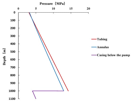
Figure 8.
Pressure distributions along the wellbore.
4.2.3. Gas Volume Fraction Profiles in Annulus
With the upward flow of the commingled fluid in the annulus, the gas volume fraction gradually increases, which is caused by the pressure drop along the annulus, as shown in Figure 9.
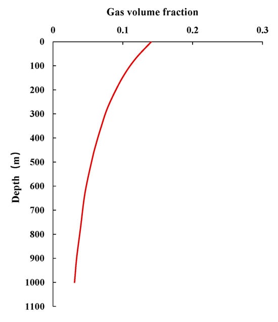
Figure 9.
Gas volume fraction profiles in the annulus.
4.2.4. Effect of Production Parameters on Flow Behavior
Gas production in the annulus is derived from the decomposition of the natural hydrate reservoir. When water production is fixed and gas production increases, the pressure gradient in the annulus decreases and the pressure drop slows down, as shown in Figure 10. The larger the GWR, the higher the pressure when flowing to the wellhead at a fixed BHP. Meanwhile, the increases in gas production can lead to changes in the physical properties of fluid and temperature distribution. An increase in gas production has a much greater effect on the pressure gradient than on the temperature gradient due to the fact that the difference between the density of the gas and the liquid is more sensitive to pressure than the difference in the specific heat capacity of the gas and the liquid is sensitive to temperature.
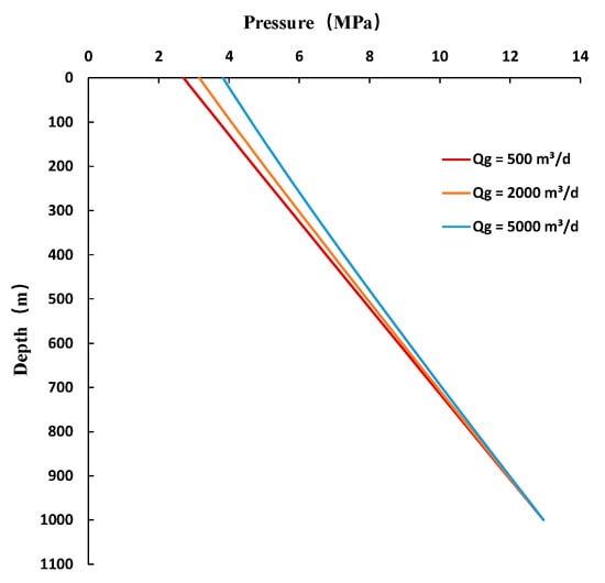
Figure 10.
Effect of gas production on pressure profile along the annulus.
4.3. Optimization of Thermal Stimulation Parameters
The temperature and pressure distribution in the wellbore of the jet pump drainage and NGH production wells are affected by injection conditions. Based on the sensitivity analysis of the multiphase flow behavior of the fluid in the jet pump drainage and NGH production wells, the thermal stimulation parameters of the jet pump wells can be optimized.
4.3.1. Injection Temperature
As displayed in Figure 11, as the injection temperature ascends, both the temperature within the annulus and tubing correspondingly increase. Increasing the injection temperature can mitigate the threat of hydrate reformation within the annulus.
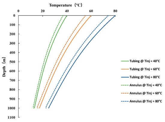
Figure 11.
Influence of injection temperature on the temperature profiles along the wellbore.
The temperature of the injected hot water is related to the risk of hydrate regeneration in the annulus during the jet pump drainage process of NGH with the combined depressurization and thermal stimulation method. The simulation results of this case well show that the closer to the wellhead, the greater the difference between the temperature of the fluid in the annulus and the phase equilibrium temperature of NGH, and therefore, the lower risk of hydrate regeneration, as shown in Figure 12. It is recommended that the temperature of injected hot water should be higher than 60 °C, which can effectively reduce the risk of hydrate regeneration for this case well. In addition, adding ethylene glycol to the power fluid of the jet pump is also an effective means to inhibit hydrate reformation in the annulus.
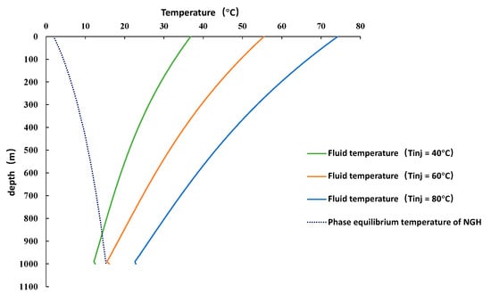
Figure 12.
Fluid temperature vs. phase equilibrium temperature in the annulus under different injection temperatures.
4.3.2. Injection Rate
As the injection rate increases, a significant rise in temperature is observed in both the tubing and annulus. In particular, the temperature distribution patterns across these two areas gradually align with a more linear trend as the injection rate reaches 500 m3/d, as displayed in Figure 13. Moreover, an increase in the injection rate can effectively circumvent possible threats from hydrate reformation in the annulus. When the injection rate increases, the injection pressure in the tubing and annulus also increases, as shown in Figure 14.
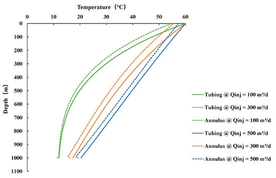
Figure 13.
Influence of injection rate on the temperature profiles along the wellbore.
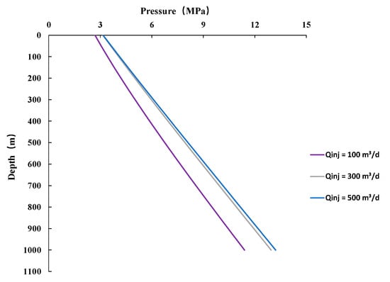
Figure 14.
Influence of injection rate on the pressure distributions along the annulus.
The difference between the phase equilibrium temperature of the hydrate at different injection rates and the temperature of fluid in the annulus are compared in Figure 15. The phase equilibrium temperature in the annulus increases with the increase in the injection rate, and there is a risk of hydrate reformation at the bottom of the annulus when the injection rate is very low. The simulation results of this case well with jet pump drainage and NGH production show that when the injection rate is greater than 300 m3/d, the phase equilibrium temperature of NGH is higher than the fluid temperature in the annulus and the risk of hydrate reformation in the wellbore can be eliminated.
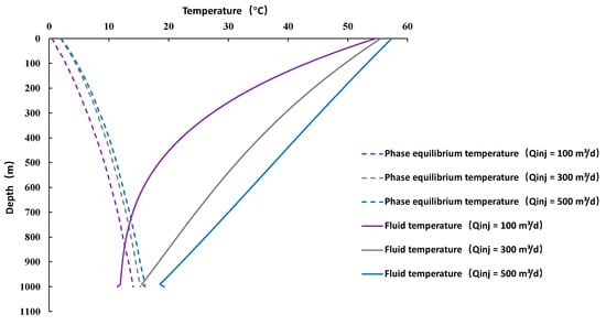
Figure 15.
Fluid temperature vs. phase equilibrium temperature in annulus at different injection rates.
4.3.3. Injection Pressure
As presented in Figure 16, it is apparent that an escalating injection pressure has a substantial influence on the pressure profile of both the tubing and the annulus. As can be seen, with increased injection pressure, the annulus pressure decreases, reducing the potential risk of hydrate reformation in the annulus.
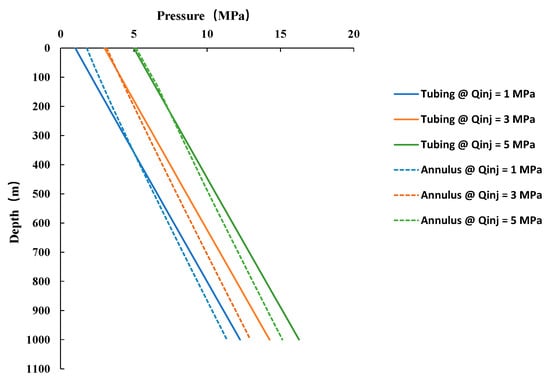
Figure 16.
Influence of injection pressure on the pressure profiles along the tubing and annulus.
From Equation (19), it can be seen that the temperature profile inside the tubing is related to the mass flow rate of hot water in the tubing, injection temperature, and other static factors. Due to the weak compressibility of the water, resulting in little change in density, regarding the mass flow rate, injection pressure has minimal impact on the temperature distribution along the tubing because the difference between the density of the gas and the liquid is more sensitive to pressure than the difference in the specific heat capacity of the gas and the liquid is sensitive to temperature. On the other hand, the annular temperature distribution is related to the temperature profile along the tubing and the surrounding formation temperature. Therefore, injection pressure has a negligible impact on the temperature distribution along the annulus when the temperature change in the tubing is very small and the surrounding temperature is constant.
5. Conclusions
The following conclusions can be reached:
(1) Compared with an ESP, jet pump drainage and gas production technology is more feasible for offshore NGH extraction with the combined depressurization and thermal stimulation method.
(2) The temperature distribution trends between the annulus and tubing of the jet pump drainage and NGH production wells with hot water as the power fluid are consistent, and the farther down the well bottom, the smaller the temperature difference. The pressure gradient in the annulus is smaller than that in the tubing and the gas volume gradually increases with the upward flow of the commingled fluid within the annulus.
(3) Despite the potential improvements in thermal stimulation effects by augmenting the injection rate and temperature of hot water, it was observed that increased injection pressure influences the pressure curve in both the tubing and the annulus without noticeably altering the temperature curve in the wellbore.
(4) There is a risk of hydrate reformation at the bottom of the annulus when the injection rate or injection temperature is low. Increasing either the injection rate or the temperature of hot fluid proves to be a robust strategy for mitigating the risk of hydrate reformation during the operation of jet pump drainage and NGH production wells.
Author Contributions
X.P.: Conceptualization, writing—original draft. J.Z.: supervision. G.H.: validation, writing—review and editing. J.C.: methodology, data curation. H.W.: resources, investigation. All authors have read and agreed to the published version of the manuscript.
Funding
This research was funded by the project of “Intelligent Real-time Prediction and Optimization Technology for Oil and Gas Production” (2023DJ8405) and “Research on Intelligent Stratified Waterflooding Engineering Technology” (2021ZG12) from PetroChina. And the APC was funded by Research Institute of Petroleum Exploration & Development, PetroChina.
Data Availability Statement
The data presented in this study are available on request from the corresponding author. The data are not publicly available due to privacy.
Acknowledgments
The authors would like to thank the Research Institute of Petroleum Exploration & Development, PetroChina, and the Key Laboratory of the Petroleum Engineering Education Ministry of the China University of Petroleum. We offer thanks to Xiaoping an and Changchun Liu’s support from the Changqing Oilfield Exploration and Development Research Institute.
Conflicts of Interest
Author Xiaolin Ping was employed by the company Research Institute of Petroleum Exploration & Development, PetroChina. The remaining authors declare that the research was conducted in the absence of any commercial or financial relationships that could be construed as a potential conflict of interest.
Nomenclatures
| density of the gas decomposed from the gas hydrate reservoir, kg/m3; | |
| density of the injected water, kg/m3; | |
| density of the water decomposed from the gas hydrate reservoir, kg/m3; | |
| mass flow rate of the gas extracted from the gas hydrate reservoir per unit volume, kg/(m3·s); | |
| mass flow rate of the water extracted from the gas hydrate reservoir per unit volume, kg/(m3·s); | |
| velocity of the injected water, m/s; | |
| velocity of the gas extracted from the gas hydrate reservoir, m/s; | |
| velocity of the water extracted from the gas hydrate reservoir, m/s; | |
| holdup of the injected water in the annulus, dimensionless; | |
| fraction of gas volume decomposed from the gas hydrate reservoir, dimensionless; | |
| holdup of the water decomposed from the gas hydrate reservoir, dimensionless; | |
| time, s; | |
| pipe length, m; | |
| pressure of the fluid in the tubing, Pa; | |
| pressure of the fluid in the annulus, Pa; | |
| gravitational constant, m/s2; | |
| inclination angle, rad; | |
| density of the mixed fluid, kg/m3; | |
| velocity of the mixed fluid, m/s; | |
| friction factor, dimensionless; | |
| diameter of the tubing, m; | |
| equivalent diameter of the annulus, m; | |
| surrounding environment temperature, °C; | |
| temperature of the fluid in the tubing, °C; | |
| temperature of the fluid in the annulus, °C; | |
| heat amount entering the element by conservation in the tubing, J; | |
| heat amount entering the element by conservation in the annulus, J; | |
| heat amount transferring from the annulus to the tubing, J; | |
| heat amount transferring from the formation by conduction, J; | |
| specific volume of the fluid in the tubing, J/(kg·°C); | |
| specific volume of the fluid in the annulus, J/(kg·°C); | |
| heat transfer coefficients of the tubing, W/(m2·K); | |
| heat transfer coefficients of the annulus, W/(m2·K); | |
| mass flow rate of the fluid in the tubing, kg/s; | |
| mass flow rate of the fluid in the annulus, kg/s; | |
| diameters of the tubing, m; | |
| diameters of the casing, m; | |
| thermal conductivity of the formation, W/(m·K); | |
| function of dimensionless time; | |
| temperature at the wellhead of the tubing, °C; | |
| injection temperature, °C; | |
| pressure at the wellhead of the tubing, Pa; | |
| injection pressure, Pa; | |
| flow rate of the fluid at the wellhead of the tubing, m3/s; | |
| injection rate, m3/s; | |
| temperature at the wellhead of the annulus, °C; | |
| measured temperature at the wellhead of the annulus, °C; | |
| environmental temperature at the bottom hole, °C; | |
| specific volume of the commingled fluid, J/(kg·°C); | |
| temperature at the bottom of the tubing, °C; | |
| temperature at the bottom of the annulus, °C; | |
| well depth, m; | |
| surface temperature, °C; | |
| geothermal gradient, °C/m. |
Abbreviations
| NGH | natural gas hydrate; |
| ESP | electric submersible pump; |
| GLR | gas–liquid–ratio; |
| GOR | gas–oil–ratio; |
| BHP | bottom head pressure. |
References
- Sakurai, S.; Nishioka, I.; Matsuzawa, M.; Matzain, B.; Goto, A.; Lee, J.E. Issues and Challenges with Controlling Large Drawdown in the First Offshore Methane-Hydrate Production Test. SPE Prod. Oper. 2017, 32, 500–516. [Google Scholar] [CrossRef]
- Yamamoto, K.; Wang, X.-X.; Tamaki, M.; Suzuki, K. The second offshore production of methane hydrate in the Nankai Trough and gas production behavior from a heterogeneous methane hydrate reservoir. RSC Adv. 2019, 9, 25987–26013. [Google Scholar] [CrossRef] [PubMed]
- Li, J.-F.; Ye, J.-L.; Qin, X.-W.; Qiu, H.-J.; Wu, N.-Y.; Lu, H.-L.; Xie, W.-W.; Lu, J.-A.; Peng, F.; Xu, Z.-Q.; et al. The first offshore natural gas hydrate production test in South China Sea. China Geol. 2018, 1, 5–16. [Google Scholar] [CrossRef]
- Ye, J.L.; Qin, X.W.; Xie, W.W.; Lu, H.L.; Ma, B.J.; Qiu, H.J.; Liang, J.Q.; Lu, J.A.; Kuang, Z.G.; Lu, C.; et al. The second natural gas hydrate production test in the South China Sea. China Geol. 2020, 3, 197–209. [Google Scholar] [CrossRef]
- Ping, X.; Han, G.; Zhang, J.; Chang, J.; Cen, X.; Tang, H. Study on the Flow Behavior of Wellbore Fluids of a Natural Gas Hydrate Well with the Combined Depressurization and Heat Injection Method. Processes 2023, 11, 1625. [Google Scholar] [CrossRef]
- Petersen, J.; Bjørkevoll, K.S.; Lekvam, K. Computing the danger of hydrate formation using a modified dynamic kick simulator. In Proceedings of the SPE/IADC Drilling Conference and Exhibition, Amsterdam, The Netherlands, 27 February–1 March 2001. [Google Scholar]
- Fu, J.; Su, Y.; Jiang, W.; Xiang, X.; Li, B. Multiphase flow behavior in deep water drilling: The influence of gas hydrate. Energy Sci. Eng. 2020, 8, 1386–1403. [Google Scholar] [CrossRef]
- Wang, Z.; Zhao, Y.; Sun, B.; Chen, L.; Zhang, J.; Wang, X. Modeling of Hydrate Blockage in Gas-Dominated Systems. Energy Fuels 2016, 30, 4653–4666. [Google Scholar] [CrossRef]
- Bassani, C.L.; Barbuto, F.A.; Sum, A.K.; Morales, R.E. Modeling the effects of hydrate wall deposition on slug flow hydrodynamics and heat transfer. Appl. Therm. Eng. 2017, 114, 245–254. [Google Scholar] [CrossRef]
- Wei, N.; Zhao, J.; Sun, W.; Zhou, S.; Zhang, L.; Li, Q.; Fu, Q.; Lü, X.; Zheng, L. Non-equilibrium multiphase wellbore flow characteristics in solid fluidization exploitation of marine gas hydrate reservoirs. Nat. Gas Ind. B 2019, 6, 282–292. [Google Scholar] [CrossRef]
- Merey, S.; Aydin, H.; Eren, T. Design of electrical submersible pumps in methane hydrate production wells: A case study in Nankai trough methane hydrates. Upstream Oil Gas Technol. 2020, 5, 100023. [Google Scholar] [CrossRef]
- Liu, Z.; Sun, B.; Wang, Z.; Lou, W.; Zhang, J. Modeling of multiphase flow in marine gas hydrate production system and its application to control the production pressure difference. J. Nat. Gas Sci. Eng. 2020, 85, 103687. [Google Scholar] [CrossRef]
- Ping, X.; Han, G.; Cen, X.; Bai, Z.; Zhu, W.; Peng, L.; Ma, B. Prediction of Pressure and Temperature Profiles and Hydrate Formation Region in ESP-Lifted Natural Gas Hydrate Wells. In Proceedings of the SPE Western Regional Meeting, Bakersfield, CA, USA, 26–28 April 2022. [Google Scholar]
- Liu, Z.; Zerpa, L.E. Preliminary Study of Liquid Loading Problems for Gas Hydrate Wells and Selection of Artificial Lift Methods. In Proceedings of the SPE Western Regional Meeting, Anchorage, AL, USA, 23–26 May 2016. [Google Scholar]
- Hasan, A.R.; Jang, M. An analytic model for computing the countercurrent flow of heat in tubing and annulus system and its application: Jet pump. J. Pet. Sci. Eng. 2021, 203, 108492. [Google Scholar] [CrossRef]
- Birkedal, K.A.; Hauge, L.P.; Graue, A.; Ersland, G. Transport Mechanisms for CO2-CH4 Exchange and Safe CO2 Storage in Hydrate-Bearing Sandstone. Energies 2015, 8, 4073–4095. [Google Scholar] [CrossRef]
- Jin, Y.; Li, S.; Yang, D.; Jiang, X. Determination of dissociation front and operational optimization for hydrate development by combining depressurization and hot brine stimulation. J. Nat. Gas Sci. Eng. 2018, 50, 215–230. [Google Scholar] [CrossRef]
- Uetani, T.; Furuichi, N.; Yorozu, H.; Sasaya, K.; Shibuya, T.; Kiminami, N.; Yonebayashi, H. Regaining Oil Production by Overcoming Emulsion Problems After Artificial Lift Installation. SPE Prod. Oper. 2017, 33, 300–312. [Google Scholar] [CrossRef]
- Kalwar, S.A.; Awan, A.Q.; Akhtar, M.S.; Hassan, R.U.; Khakwani, K.M. Successful Application of Jet Pump Technology for Production Optimization in a Brown Oil Field—A Case Study in Pakistan. SPE Middle East Artificial Lift Conference and Exhibition. In Proceedings of the SPE Middle East Artificial Lift Conference and Exhibition, Manama, Bahrain, 25–26 October 2022. [Google Scholar]
- Hasan, A.R.; Kabir, C.S. A Mechanistic Model for Computing Fluid Temperature Profiles in Gas-Lift Wells. SPE Prod. Facil. 1996, 11, 179–185. [Google Scholar] [CrossRef]
- Kurihara, M.; Sato, A.; Funatsu, K.; Ouchi, H.; Ashford, D. Analysis of Production Data for 2007/2008 Mallik Gas Hydrate Production Tests in Canada. In Proceedings of the International Oil and Gas Conference and Exhibition in China, Beijing, China, 8–10 June 2010. [Google Scholar]
Disclaimer/Publisher’s Note: The statements, opinions and data contained in all publications are solely those of the individual author(s) and contributor(s) and not of MDPI and/or the editor(s). MDPI and/or the editor(s) disclaim responsibility for any injury to people or property resulting from any ideas, methods, instructions or products referred to in the content. |
© 2024 by the authors. Licensee MDPI, Basel, Switzerland. This article is an open access article distributed under the terms and conditions of the Creative Commons Attribution (CC BY) license (https://creativecommons.org/licenses/by/4.0/).