Article

Study on Geological Deformation of Supercritical CO2 Sequestration in Oil Shale after In Situ Pyrolysis

1
Shaanxi 194 Coal Geological Co., Ltd., Tongchuan 727007, China
2
College of Construction Engineering, Jilin University, Changchun 130026, China
*
Author to whom correspondence should be addressed.
Energies 2024, 17(15), 3849; https://doi.org/10.3390/en17153849
Submission received: 24 June 2024 / Revised: 23 July 2024 / Accepted: 31 July 2024 / Published: 5 August 2024
(This article belongs to the Special Issue Recent Advances in Oil Shale Conversion Technologies)

Abstract

:
After the completion of in situ pyrolysis, oil shale can be used as a natural place for CO2 sequestration. However, the effects of chemical action and formation stress-state changes on the deformation of oil shale should be considered when CO2 is injected into oil shale after pyrolysis. In this study, combined with statistical damage mechanics, a transverse isotropic model of oil shale with coupled damage mechanisms was established by considering the decreased mechanical properties and the chemical damage caused by CO2 injection. The process of injecting supercritical CO2 into oil shale after pyrolysis was simulated by COMSOL6.0. The volume distribution of CO2 and the stress evolution in oil shale were analyzed. It is found that CO2 injection into oil shale after pyrolysis will not produce new force damage, and the force damage caused by the decrease in the mechanical properties of oil shale after pyrolysis can offset the ground uplift caused by CO2 injection to a certain extent. Under the combined action of chemical damage and mechanical damage, the uplift of a formation with a thickness of 200 m is only 10 cm. The injection of supercritical CO2 is beneficial for maintaining the stability of oil shale after in situ pyrolysis.

1. Introduction

Oil shale, as an alternative energy source of fossil energy [1], exists in huge reserves around the world [2]. Technology for its in situ exploitation is regarded as a direction of future development, so it has been extensively studied and developed [3]. The in situ exploitation of oil shale means that it is pyrolyzed underground through in situ exploitation technology. After pyrolysis, the porosity of the oil shale layer increases, and the mechanical properties decrease significantly. Therefore, environmental geological problems such as land subsidence and deformation [4] may be faced after exploitation, which will destroy land resources [5] and affect economic development [6]. In recent years, carbon dioxide capture and storage (CCS) has been recognized as a core strategy for achieving a low-carbon future, and as a technology for reducing CO2 emissions, it has shown great prospects and potential [7]. However, the storage of CO2 underground will affect the mechanical properties of rock masses, resulting in a series of geological problems, such as reduced layer strength [8], surface uplift and deformation [9]. After the completion of in situ pyrolysis, the oil shale layer is a medium with high porosity and permeability [10] that strongly adsorbs CO2 and can be used as a favorable natural place for CCS. At the same time, the surface uplift and deformation caused by CCS can also improve the ground settlement caused by oil shale pyrolysis to a certain extent. However, oil shale after pyrolysis has low mechanical properties [11] and is prone to plastic deformation failure, which makes the final deformation difficult to estimate. Therefore, it is crucial to study the deformation mechanism of oil shale after pyrolysis under the action of force damage and CO2 chemical damage.
After the completion of pyrolysis, the porosity of the oil shale is extremely high, and the mechanical properties are greatly reduced. During the process of CO2 injection, the stress change caused by the change in pore pressure in oil shale means that plastic deformation easily occurs. Therefore, the mechanical properties of oil shale after pyrolysis determine the deformation during the process of CO2 injection. Previous studies have found that oil shale is an anisotropic heterogeneous material [12], and its mechanical properties [13] have obvious anisotropic characteristics. After the pyrolysis of oil shale, due to the irreversible damage caused by thermal stress concentration and the pyrolysis of organic matter, the elastic modulus and compressive strength of oil shale in the longitudinal and parallel bedding directions are reduced to varying degrees [11]. In order to accurately reflect the law of mechanical property reduction after the in situ pyrolysis of oil shale, damage to the rock mass can be considered to follow a Weibull distribution [14], and the study of mechanical damage is conducted by combining mechanical experiments with failure criteria [15]. In previous studies, the mechanical properties of oil shale after heating at different temperatures were obtained through experiments, and a statistical constitutive model of the mechanical damage of oil shale after high-temperature treatment was established based on the Drucker–Prager criterion [16]. However, this model regards the rock mass as isotropic and cannot explain the different damage characteristics caused by forces in different directions. It can be seen that the anisotropy of the mechanical properties of oil shale after pyrolysis is a key problem in studying the deformation caused by CO2 injection into oil shale after pyrolysis, and further research is needed.
CCS requires the injection of CO2 into porous underground rock formations. During the injection process, the chemical reaction between CO2 and the rock mass will cause changes in the pore pressure and mechanical properties of the rock mass, which is a complex multi-field coupling problem. Currently, the coupling process of CO2 geological storage is mostly analyzed through numerical simulations [17]. In previous studies, by studying the interactions between temperature changes, chemical reactions, solute transport and rock mechanical properties, numerical simulations were carried out to analyze changes in the stress, strain and porosity of rocks around the wellbore under chemical effects [18,19]. Based on the TOUGH-FLAC 3D multi-phase and multi-component THM coupling numerical simulation program, some scholars have developed a site-scale rock-mass-cracking module to study the comprehensive effects of CO2 injection schemes on the coupling and cracking characteristics of target aquifers [20]. However, due to the complex mechanical properties of oil shale after pyrolysis, it is necessary to rewrite the constitutive equation of the rock mass to study the injection of CO2 into pyrolyzed oil shale. COMSOL Multiphysics software allows the user to define the constitutive model of rock mass deformation through mathematical fields, which is suitable for the numerical simulation of rock mass deformation in complex coupled environments [21]. Moreover, COMSOL Multiphysics is also powerful software for studying the CCS process, as it can realize multi-field coupling geo-mechanical modeling of the CO2 injection process. This software can simulate the seepage, deformation and other processes in the process of CCS and is one of the most widely used programs at present [22,23]. Therefore, COMSOL6.0 was used to study the formation deformation of supercritical CO2 storage in oil shale after pyrolysis in this study.
In this study, a transverse isotropic coupled damage model of oil shale was established by considering the force damage caused by the decrease in the mechanical properties of oil shale after pyrolysis and the chemical damage caused by CO2 injection, combined with statistical damage mechanics. The process of injecting supercritical CO2 into oil shale after pyrolysis was simulated by COMSOL6.0. The volume distribution of supercritical CO2 and the stress changes in the rock mass in oil shale during the injection process were analyzed. Combined with stress damage and chemical damage factors, the deformation of the rock mass in the oil shale formation after supercritical CO2 injection pyrolysis was studied. The simulation results in this paper can provide theoretical support for carbon storage in oil shale after in situ exploitation.

2. Geological Background

As shown in Figure 1 [24], the study area of this project is located in the town of Jin Suoguan, Tongchuan City, Shaanxi Province, China, which is geologically located in the Ordos Basin. In response to the low-carbon concept and the development trend toward carbon neutrality, the injection of supercritical carbon dioxide into the oil shale formation after pyrolysis is planned for a later stage of the project.
The Yanchang Formation in the Ordos Basin is the best-developed Triassic stratigraphic section in the continental strata. The Triassic Yanchang Formation is a set of alluvial fan–fan delta–fluvial lacustrine facies composed of terrigenous clastic rock deposits. The Yanchang Formation is composed of 10 members, Ch10–Ch1, of which Ch7 is the main distribution member of the source rocks. The TOC content of oil shale in CH7 is the highest, with an average of 13.75%. The kerogens are type I and type II, and the hydrogen index (HI) is up to 750 mg/g [24,25].

3. Model Building

3.1. Basic Assumptions

  • The oil shale formation is located below 200 m underground, and the CO2 injection pressure is relatively large. During the injection process, the pore pressure of the oil shale layer exceeds the critical CO2 pressure value, so the injected fluid is regarded as a supercritical CO2 fluid.
  • After the injection of supercritical CO2 into oil shale after pyrolysis, its seepage channels are mainly concentrated in the cracks generated by the pyrolysis and are considered to be in a state of high pressure, saturated by fluids.
  • The gradients of fluid pressure and percolation velocity in oil shale follow Darcy’s law.
  • The oil shale layer is in a water-saturated state after pyrolysis, and the relationship between injected supercritical CO2 and pore water follows the Brooks–Corey capillary pressure model.
  • A CO2–water–rock reaction occurs between supercritical CO2 and the water-saturated rock mass, which affects the mechanical properties of oil shale. The equilibrium state of the CO2–water–rock reaction is proportional to the concentration of CO2.
  • Oil shale is a sedimentary structure and is regarded as a transverse isotropic material, and the mechanical properties of oil shale after pyrolysis are greatly reduced. The mechanical damage caused by the coupling of the pore stress-state change and the chemical damage caused by the CO2–water–rock reaction are mainly considered in the process of supercritical CO2 injection.

3.2. Control Equation of Mixed-Fluid Seepage

According to the law of conservation of mass, the seepage control equation of the mixed fluid formed with water after supercritical CO2 injection into oil shale can be expressed as
d i v ρ H q i = ( n ρ H ) t      
ρ H = S 1 × ρ W + S 2 × ρ C    
where ρH is the density of the mixed fluid; ρW and ρC are the densities of water and supercritical CO2, respectively; S1 and S2, calculated by the Brooks–Corey capillary pressure model built into COMSOL6.0, are the volume fractions of water and supercritical CO2 in the mixed fluid, respectively; qi (i = x, y, z) is the flow rate of fluid per unit time in the x-, y-, and z-directions, respectively; n is the porosity of oil shale; and t is the time.

3.3. Transversely Isotropic Static Equilibrium Equation

The differential equation of the rock matrix deformation field is as follows:
d i v C ε i j   + α δ i j p + F = 0
where C is the elastic matrix considering transverse isotropy, δ i j is the second-order identity tensor, α is the Biot coefficient, p is the pore pressure, and F is the physical force component matrix. Since oil shale can be regarded as a transversely isotropic material, C can be expressed as
C = C 11 C 12 C 13 C 12 C 11 C 13 C 13 C 13 C 33                 0 0 0 0 0 0 0 0 0 0 0 0 0 0 0 0 0 0 C 44 0 0 0 C 44 0 0 0 C 66       C 11 = E p a r ( E p e r E v p e r 2 ) Γ C 33 = E p e r ( 1 v p e r 2 ) Γ C 12 = E p a r ( E p e r v p a r + E p a r v p e r 2 ) Γ C 13 = E p a r E p e r v p e r ( 1 + v p e r ) Γ C 44 = G p e r = E p a r E p e r E p a r 1 + 2 v p e r + E p e r C 66 = C 11 C 12 2 Γ = 1 1 + v p a r [ 1 v p a r E p a r 2 v p e r 2 E p a r ]
where Epar is the elastic modulus in the parallel bedding direction, Eper is the elastic modulus in the vertical bedding direction, υpar is Poisson’s ratio in the parallel bedding direction, and υper is Poisson’s ratio in the vertical bedding direction. Gper is the shear modulus in the vertical bedding direction and is calculated according to the formula obtained from Lekhnitskii’s laboratory rock test [26].

3.4. Establishment of Damage Evolution Equation

The mechanical properties of the oil shale layer after pyrolysis are greatly reduced, and it is more prone to plastic deformation or even destruction than the non-pyrolyzed oil shale layer under the same stress. Therefore, compared with the general rock layer, when supercritical CO2 is injected into the oil shale layer after pyrolysis, the mechanical damage caused by the change in the stress state cannot be ignored. Therefore, a coupled damage model of oil shale was constructed considering the chemical damage caused by the CO2–water–rock reaction and the stress damage caused by the stress-state change.
According to the Lemaitre damage model, under the coupled action of chemical damage and mechanical damage, the stress–strain relationship of oil shale is as follows:
σ = E 0 [ 1 D 1 ] [ 1 D 2 ] ε
where D1 is the chemical damage caused by the CO2–water–rock reaction, and D2 is the mechanical damage caused by the stress-state change.
Therefore, the elastic moduli Epar and Eper after damage conform to the following functional relationship:
E p a r / p e r D = E p a r / p e r [ 1 D 1 ] [ 1 D 2 ]

3.4.1. CO2–Water–Rock Chemical Damage

In the process of CO2 geological storage, minerals will dissolve or precipitate after the chemical reaction between water and the rock mass, resulting in changes in the mechanical properties of oil shale. The chemical damage equation of rock is as follows:
D 1 = i = 1 n M i × γ i ρ d V d 1 φ 0 × 100 %
where Mi is the molar mass of the mineral; γi is the molecular weight involved in the chemical reaction when the dissolution of the mineral reaches equilibrium; ρd is the dry density of the rock mass; and Vd is the solid volume of the rock mass.

3.4.2. Stress Damage

After pyrolysis, the mechanical properties of oil shale are greatly reduced, and plastic sections are more prone to failure under the action of stress. Many scholars believe that rock element strength k follows a Weibull distribution:
f k = m F k F m 1 e x p k F m   k > 0 0                                                                                             k 0
where m reflects the homogeneity characteristics of the material, and F is a parameter related to the mechanical properties.
In the definition of damage, the initial damage in the material is ignored, and it is assumed that the continuous destruction of the microelement leads to damage evolution in the yield section of the material. The definition of damage is as follows:
D 2 = V P V
where D2 is the stress damage variable, VP is the volume of damaged units in the rock material, and V is the total volume of the rock material.
At a certain stress level [σ], the internal failure volume of the rock mass is
V P = V   0 k f t d t d x d y d z
Since the strength distribution function does not change with the spatial coordinates, the damage variable can be expressed as
D 1 = V P V = V 0 k f t d t V = 0 k f t d t = 1 e x p k F m
The Drucker–Prager strength criterion considering the intermediate principal stress is adopted as the failure criterion for the microelement:
k = α I 1 * + J 2 * = K
K = 3 c c o s φ 3 3 + s i n 2 φ I 1 * = σ 1 * + σ 2 * + σ 3 * J 2 * = 1 6 σ 1 * σ 2 * 2 + σ 1 * σ 3 * 2 + σ 2 * σ 3 * 2
where α is a material parameter, K is a rock strength parameter, c is the cohesion, φ is the internal friction angle, I 1 * is the first invariant of the stress tensor expressed by the effective stress, J 2 * is the second invariant of stress deviation, and σ i * (i = 1, 2, 3) is the effective stress.
When supercritical CO2 is injected into the oil shale layer, chemical damage and mechanical damage occur simultaneously, and the reduction in the mechanical properties of the rock mass caused by chemical damage will change the original stress state of the oil shale and increase the effective stress. In this case, the effective stress of the rock mass is as follows:
σ i * = σ i 1 D 1
where σi (i = 1, 2, 3) is the stress on the oil shale.
After K is selected as the strength parameter, the parameters F and m also become parameters related to cohesion and the internal friction angle due to Formula (13). Referring to Zhang Yujun et al. [27], cohesion and the internal friction angle are defined as functions of the angle between the maximum principal stress σ1 and the bedding, so the mechanical parameters F and m are written as functions of the angle between the maximum principal stress σ1 and the bedding:
F = 2 θ π F 1 F 2 + F 2 m = 2 θ π m 1 m 2 + m 2
where F1, F2, m1 and m2 are the values of F and m when the maximum principal stress is in the vertical and parallel bedding directions, and θ is the angle between the maximum principal stress and the bedding.
Combining Formulas (4), (6), (7) and (16), the oil shale deformation constitutive model considering the chemical damage caused by the CO2–water–rock reaction and the stress damage caused by the stress-state change can be written as follows:
ε x ε y ε z γ x y γ z y γ x z = 1 E 1 υ p E 1 υ v E 2 0 0 0 υ p E 1 1 E 1 υ v E 2 0 0 0 υ v E 2 υ v E 2 1 E 2 0 0 0 0 0 0 2 1 + υ v E 1 0 0 0 0 0 0 1 G v 0 0 0 0 0 0 1 G v σ x σ y σ z τ x y τ z y τ x z E 1 = E p a r 1 D 1 1 D 2 E 2 = E p e r 1 D 1 1 D 2

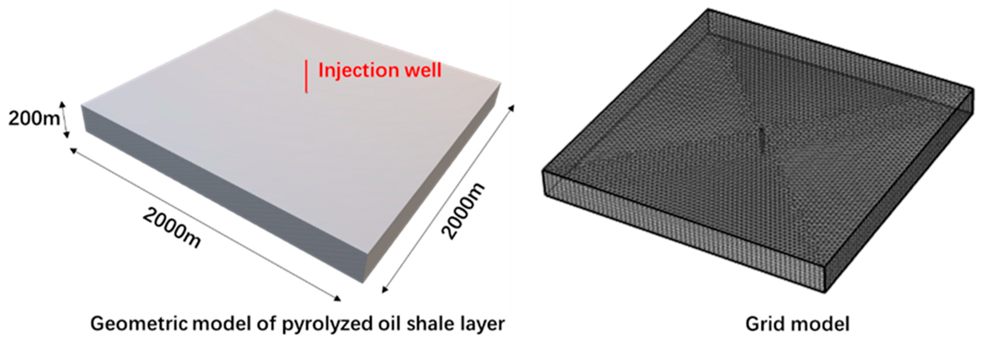
4. Geometric Model and Calculation Parameters

COMSOL can build a multi-field coupling model through the built-in multi-field interface or a custom multi-field coupling relationship. In this study, the solid mechanics and Darcy’s law mathematical fields were used to combine the solid mechanics and percolation fields with the coupled damage constitutive model to establish the final CO2 sequestration model of the oil shale layer after pyrolysis.

4.1. Simplification of Calculation Model

In order to directly reflect the deformation caused by the injection of supercritical CO2 into pyrolyzed oil shale, the simulated pyrolyzed oil shale is regarded as a layered hexahedron, and the simulated oil shale reservoir is a cubic porous medium with dimensions of 2000 × 2000 × 200 m, with a subsurface depth of about 200 m, as shown in Figure 2. The injection well is centered. In order to ensure the smooth calculation of the model in the two-phase-flow physical field, a refined free triangular mesh was used on the upper surface of the model, and the mesh was calibrated to the fluid dynamics control. After that, a sweeping mesh was used to divide the whole geometric model into nine layers in the Z-axis direction, and the final geometry was divided into more than 100,000 grids.

4.2. Simplification of Calculation Model

The solid deformation field boundary conditions are as follows: the x = 0 surface displacement boundary is u = 0; the y = 0 surface displacement boundary is v = 0; and the z = 0 surface displacement boundary is w = 0. The buried depth of oil shale is 200 m, assuming that the average volume weight of the overlying strata is 25,000 N/m3, and the lateral pressure coefficient is 0.8. Then, the overlying pressure σ z of the oil shale layer is 5 MPa, and the horizontal lateral pressure of the top of the oil shale layer is 4 MPa. Considering the influence of vertical deformation on the lateral pressure, the lateral pressure of the oil shale layer is as follows:
σ x / y = 4   M P a + ρ R g h v E p a r E p e r
where ρR is the density of the oil shale layer, and h is the height from any position in the oil shale layer to the bottom of the formation.
The boundary conditions of the seepage field are as follows: an injection well is set in the center of the model, and the injection rate is 15 kg/s. There is no flow above or below the model. The research area of this model is sufficiently large, and in order to enhance the convergence of the model, the boundary of the model side is set far enough from the injection well; the influence of supercritical CO2 injection on the model boundary can be ignored, so the pressure at the boundary of the model side is p = ρ w g h .

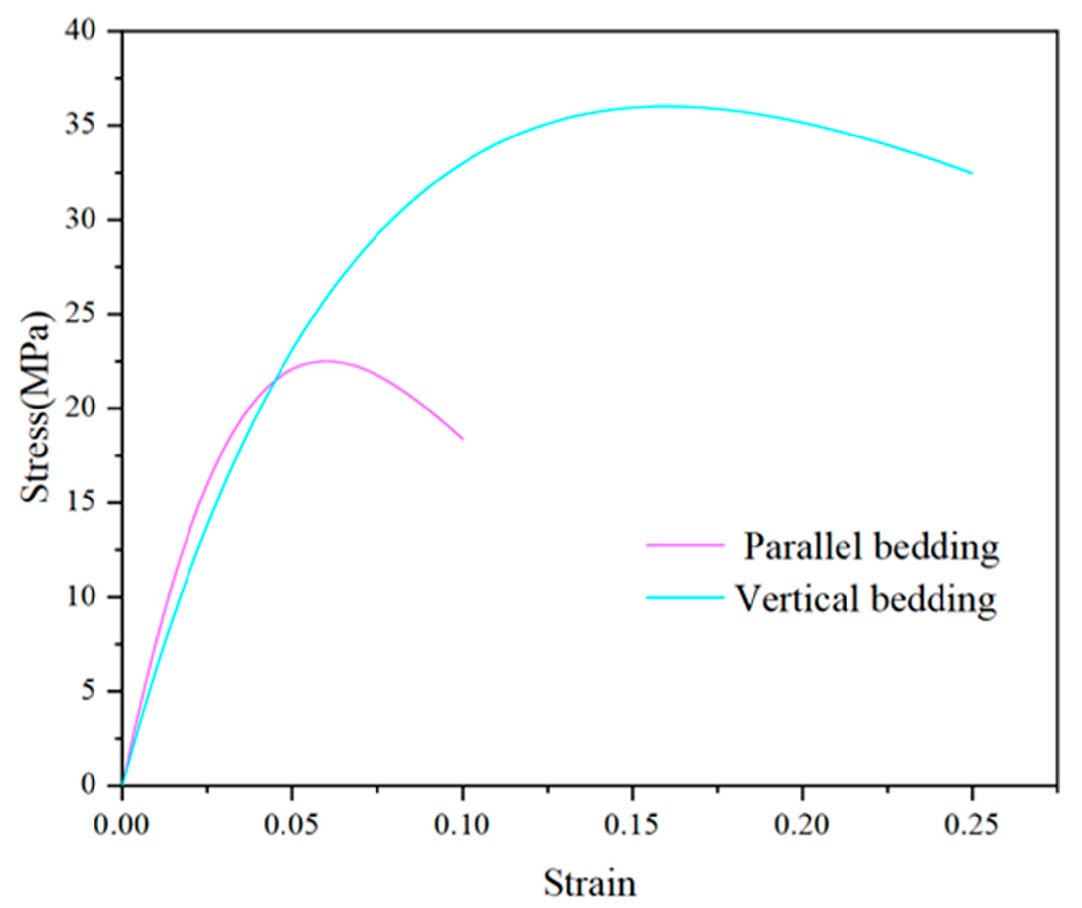
4.3. Parameter Selection for Transverse Isotropic Mechanical Simulation

Ordos Tongchuan oil shale was selected as the oil shale in the simulation, which undergoes elastic deformation and brittle failure before pyrolysis. The mechanical parameters in the parallel and vertical bedding directions at normal temperatures are shown in Table 1 [24]. The mechanical properties of oil shale decrease significantly after pyrolysis, and plastic failure occurs with the increase in stress. According to the conclusions of previous studies, it is assumed that the strength and elastic modulus of Tongchuan oil shale after pyrolysis decay to 1/3 their initial values at normal temperatures, and the failure strain increases to twice that at normal temperatures [28]. The mechanical parameters after pyrolysis are shown in Table 2.
According to the mechanical parameters after pyrolysis, the stress damage parameters of pyrolyzed oil shale were calibrated, and the parameter results are shown in Table 3. The theoretical uniaxial stress–strain curve of Tongchuan oil shale after pyrolysis is drawn according to the statistical damage deformation constitutive equation, as shown in Figure 3.

4.4. Selection of Other Simulation Parameters

According to the research conclusion of Huang Yinghua [29], the average damage parameter of the CO2–water–rock reaction after the injection of supercritical CO2 into wet shale at 30 MPa with respect to the mechanical properties of shale is 0.4. Therefore, in this study, the chemical damage when the volume fraction of CO2 in the mixed fluid is 80% is set to 0.4. The molecular weights of chemical reactants in the rock mass are proportional to the volume fraction of CO2.
In this study, the porosity and permeability of oil shale after pyrolysis are set to 0.2 and 8 md, respectively.

5. Simulation Results and Analysis

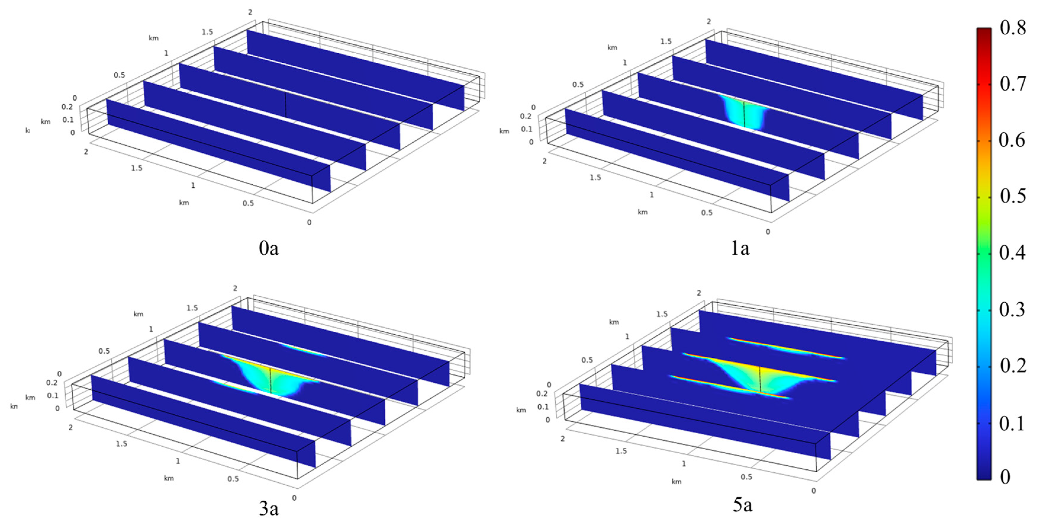
5.1. Distribution of CO2 Volume Fraction

The volume fraction distribution of supercritical CO2 after injection into the oil shale layer is shown in Figure 4. Before the injection, the volume fraction of supercritical CO2 in the layer is 0. With the injection of supercritical CO2, the volume fraction of supercritical CO2 increases around the injection well, forming a cylindrical area with a radius of about 200 m, and the volume fraction of CO2 in the cylinder area is about 0.3. As supercritical CO2 continues to be injected into the injection well, the volume fraction of supercritical CO2 gradually diffuses to the top of the oil shale layer because the density of supercritical CO2 is lower than that of water. After supercritical CO2 is injected into a saturated oil shale formation, water is pushed to the bottom of the oil shale under the action of gravity, while supercritical CO2 diffuses to the top of the layer. Finally, in the fifth year of injection, supercritical CO2 forms an inverted conical distribution area with a radius of 600 m and a height of 200 m in the oil shale layer.

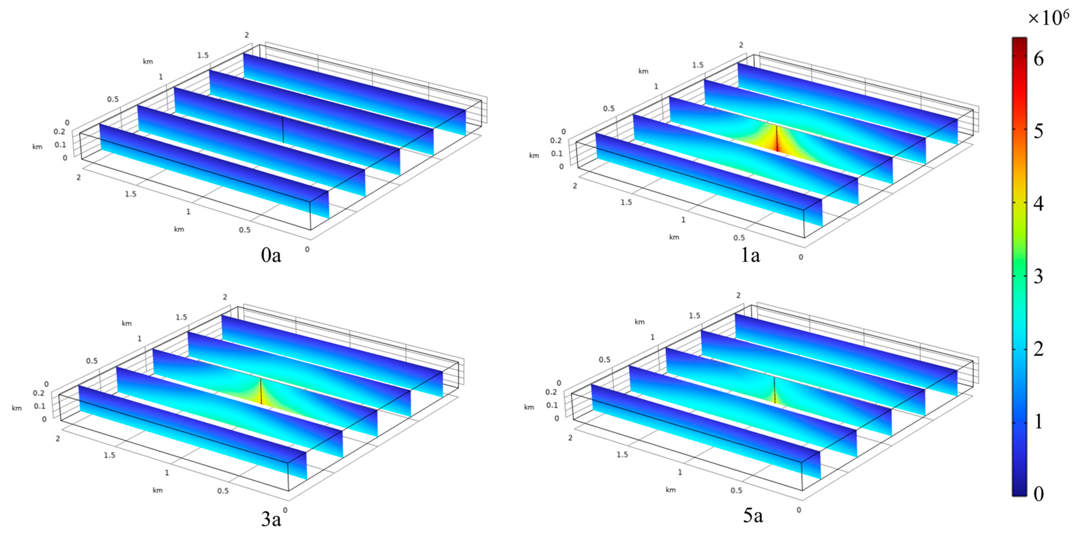
5.2. Pore Pressure Distribution

The pore pressure distribution after supercritical CO2 injection into the oil shale layer is shown in Figure 5. Before the injection, the pore pressure in the layer is mainly generated by the water in the pores. As the layer depth increases, the pore pressure at the bottom of the oil shale formation reaches 1.9 MPa with the maximum pore pressure. With the injection of supercritical CO2, the pore pressure around the injection well increases rapidly, and the bottom well pressure is the largest. In the first year, the pore pressure at the bottom of the well exceeded 6 MPa, the layer pore pressure gradually decreased with the increase in the distance from the injection well, and the pore pressure at the bottom of the oil shale was higher than that at the top. Combined with the distribution of the volume fraction of supercritical CO2, this is because the density of supercritical CO2 is relatively low. After the injection of supercritical CO2 into the oil shale formation, it mainly flows to the top of the layer. This pore pressure distribution causes the maximum pore pressure difference in the process of supercritical CO2 migration and ensures that a flow state occurs above the syncline of supercritical CO2. As the injection progresses, the concentration of pore pressure around the injection well gradually dissipates to the surrounding areas, and finally, by the fifth year of injection, the pore pressure at the bottom of the injection well has dissipated to 4.15 MPa.

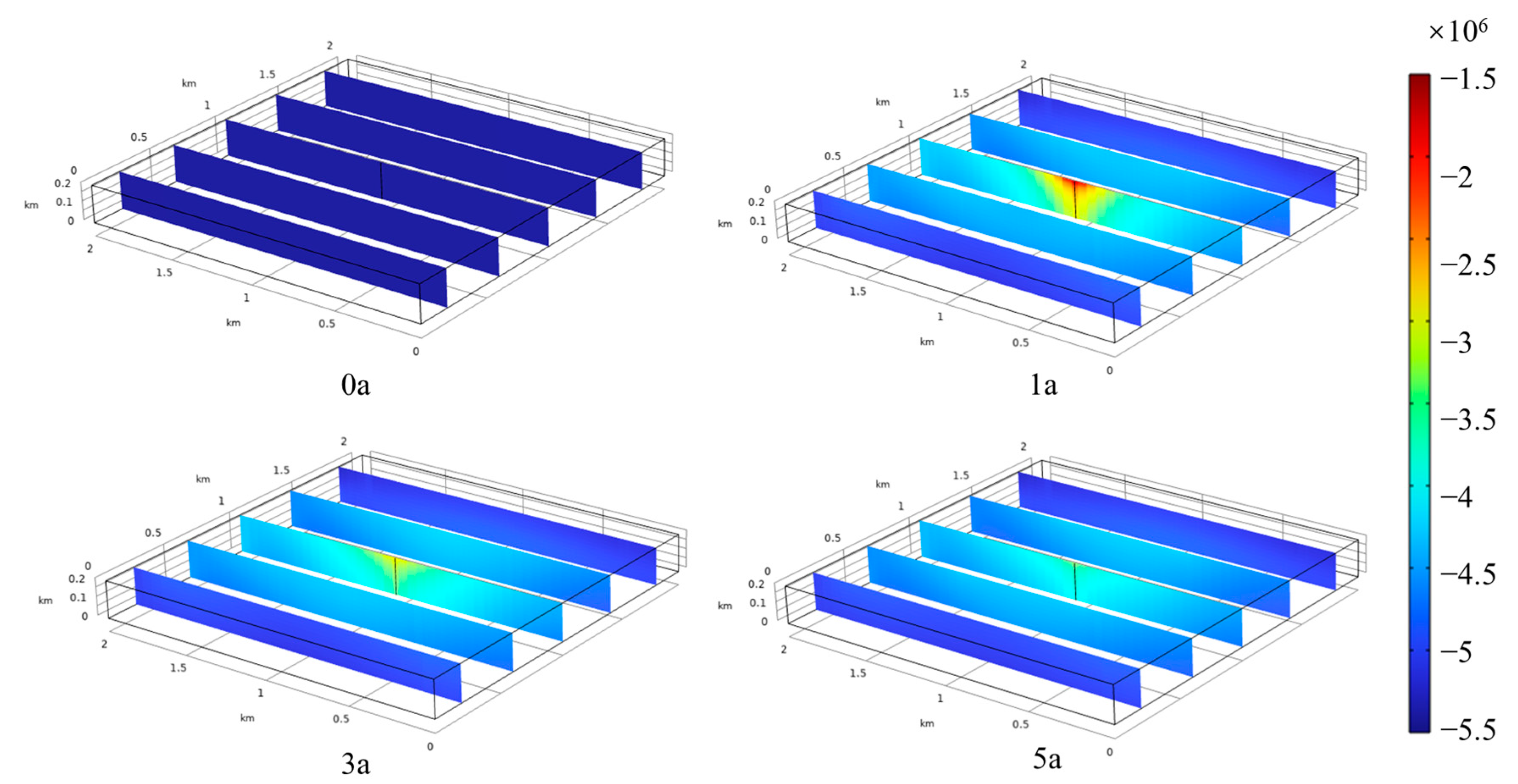
5.3. Stress-State Distribution

The horizontal stress distribution of the oil shale layer after supercritical CO2 injection is shown in Figure 6. Before the injection, the stress of the rock mass in the layer depends on the ground stress exerted on the layer. The horizontal stress increases slightly with the layer depth, and the stress at the bottom is the largest, which is 5.4 MPa. With the injection of supercritical CO2, the pore pressure inside the rock mass increases, resulting in a reduction in the effective stress of the rock mass and the swelling deformation of the oil shale. Due to the higher pore pressure at the bottom of the oil shale layer, the expansion deformation at the bottom of the oil shale layer is larger. Since the bottom oil shale is connected to the upper oil shale, the expansion deformation of the bottom oil shale will have a certain stretching effect on the upper oil shale, resulting in a degree of elastic expansion of the upper oil shale. This significantly reduces the horizontal stress in the top oil shale around the injection well. In the first year, the pore pressure in the oil shale layer is the largest, resulting in the most significant reduction in the effective stress in the layer, which decreases to 1.5 MPa at the top of the injection well. As injection progresses, the concentration of pore pressure in the layer gradually dissipates to the surrounding areas, and the reduction in effective stress caused by it gradually weakens. Finally, the horizontal stress at the top of the injection well is 3.37 MPa in the fifth year of injection.
The vertical stress distribution of the oil shale layer after supercritical CO2 injection is shown in Figure 7. Before the injection, the vertical stress of the rock mass in the layer depends on the ground stress and the weight of the rock mass. The vertical stress increases with the depth of the layer, and the maximum stress is 7.1 MPa at the bottom. The vertical stress of the top oil shale around the injection well is also significantly reduced due to the distribution of pore pressure in the oil shale layer. In the first year, the pore pressure in the oil shale formation causes the most significant reduction in effective stress in the formation, which decreases to 0.8 MPa at the top of the injection well. With the progress of injection, the concentration of pore pressure in the layer gradually dissipates to the surrounding areas, and the reduction in effective stress caused by it gradually weakens. Finally, in the fifth year of injection, the vertical stress at the top of the injection well is 2.75 MPa.

5.4. Damage Parameters

The distribution of chemical damage caused by the injection of supercritical CO2 into the oil shale layer is shown in Figure 8. With the injection of supercritical CO2, the volume fraction of supercritical CO2 continues to increase, and when the reaction equilibrium is reached, the molecular weights of the minerals that react in oil shale continue to increase, and the mechanical properties continue to decrease. In the first year, a cylindrical area with a radius of about 200 m is formed around the injection well, and the chemical damage D1 caused by CO2 in the cylindrical area is about 0.15. With the continuous injection of supercritical CO2 into the injection well, the volume fraction of supercritical CO2 gradually diffuses to the top of the oil shale layer. Finally, in the fifth year of injection, supercritical CO2 forms an inverted conical damage area with a radius of 600 m and a height of 200 m in the oil shale layer, and D1 at the most intense damage is 0.32.
The distribution of stress damage in the pyrolyzed oil shale layer after supercritical CO2 injection is shown in Figure 9. Before supercritical CO2 injection, mechanical damage D2 is generated in the oil shale layer under the original in situ stress condition due to the decrease in mechanical properties after pyrolysis. The D2 value at the top of the formation is the smallest (0.0555), while the D2 value at the bottom is the largest (0.086). With the injection of supercritical CO2, the effective stress inside the oil shale decreases, so the resulting stress damage decreases accordingly. However, since the damage is irreversible, the final stress damage D2 in the process of supercritical CO2 injection is the damage caused by the original in situ stress without the injection of supercritical CO2.

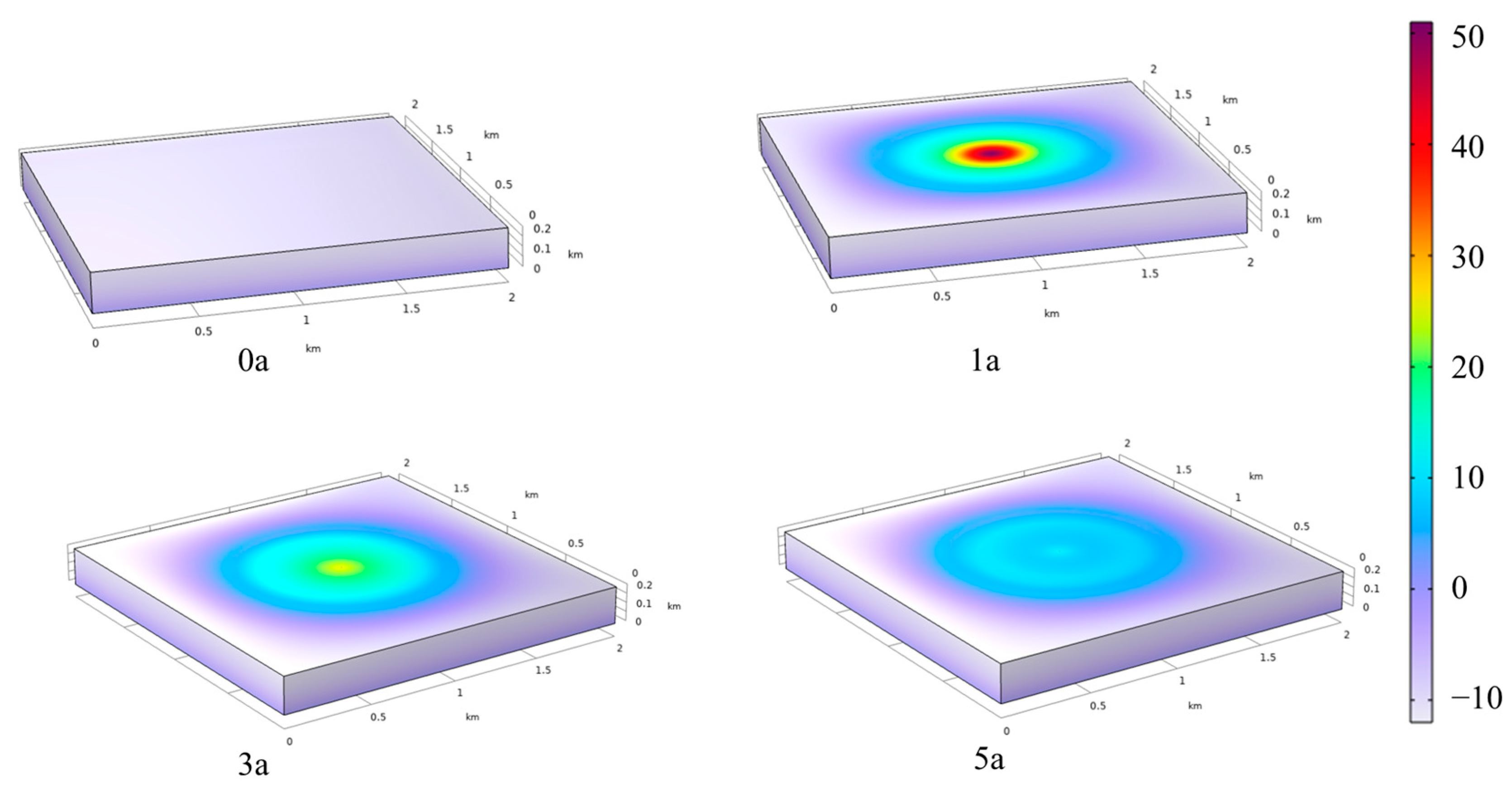
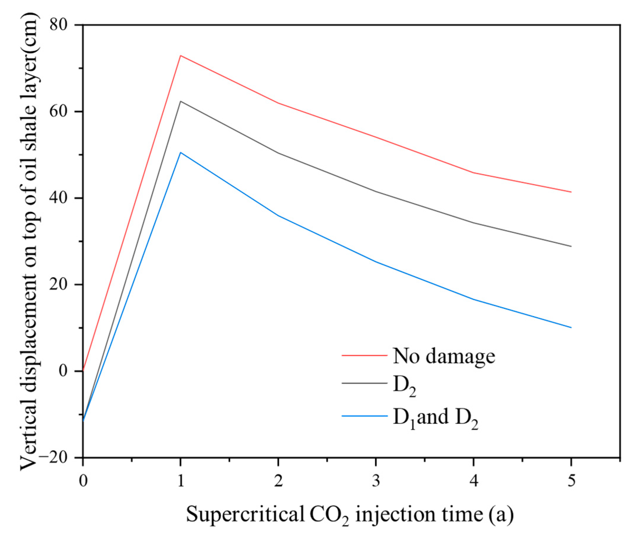
5.5. Deformation Field Distribution

The vertical deformation at the top of the oil shale layer after pyrolysis and supercritical CO2 injection is the main factor that causes surface deformation. The displacement distribution at the top of the oil shale layer is shown in Figure 10. Before supercritical CO2 injection, the oil shale layer settlement is about 11 cm due to the force damage caused by the decrease in mechanical properties after pyrolysis. An equivalent displacement circle will form at the top of the formation centered on the injection well, and the nearer the injection well is, the greater the vertical expansion displacement will be. In the first year, the layer expansion displacement reaches the maximum, and the vertical expansion displacement at the injection well reaches 50.5 cm. With the progress of injection, the pore pressure around the injection well continues to dissipate, and the layer expansion deformation decreases. Finally, by the fifth year, 10.1 cm vertical expansion deformation has occurred within a radius of 600 m around the injection well.
The vertical displacement at the injection well in different damage states is shown in Figure 11. When the stress damage and chemical damage are not considered, the vertical expansion displacement at the injection well reaches 72.9 cm in the first year, and finally, the vertical expansion deformation around the injection well reaches 41.4 cm in the fifth year. When chemical damage is not considered, the vertical expansion displacement at the injection well reaches 62.3 cm in the first year, and finally, the vertical expansion deformation around the injection well reaches 28.9 cm in the fifth year. The ground subsidence caused by the decrease in mechanical properties due to the pyrolysis of oil shale can offset the ground uplift caused by the injection of supercritical CO2 to a certain extent, and the pore pressure in the oil shale layer increases after the injection of supercritical CO2. The effective stress in the rock layer decreases; therefore, even if the mechanical properties of the oil shale layer decrease after pyrolysis, additional force damage will not occur during the injection process. It can be seen that injecting supercritical CO2 into oil shale after pyrolysis can effectively maintain the stability of the oil shale layer after in situ pyrolysis.

6. Conclusions

In this study, the chemical damage to oil shale caused by supercritical CO2 and the stress damage caused by the reduction in the mechanical properties of oil shale after pyrolysis are considered. Combined with statistical damage mechanics, a transverse isotropic damage-coupling model of oil shale after supercritical CO2 injection is established. A numerical simulation of oil shale after supercritical CO2 injection and pyrolysis was carried out through the coupling of COMSOL6.0 mathematical fields. The conclusions are as follows:
  • After the injection of supercritical CO2 into the oil shale, as the density of CO2 is lower than that of water, supercritical CO2 gradually diffused to the top of the oil shale and eventually formed an inverted conical distribution area with a radius of 600 m and a height of 200 m. Due to the transport mode of supercritical CO2, the pore pressure in the formation reached its maximum at the bottom of the injection well and gradually decreased at the top and surrounding the formation.
  • After the injection of supercritical CO2 into oil shale, the effective stress in the rock mass decreased due to the increase in pore pressure. Since the pore pressure at the bottom of the rock layer was the largest, the expansion at the bottom was large, and then the displacement of the rock mass at the bottom played a stretching role in the top rock mass, resulting in the greatest reduction in pressure occurring at the top of the oil shale layer. The most significant reduction in effective stress occurred in the first year, with horizontal and vertical stresses at the top of the injection well decreasing to 1.5 and 0.8 MPa, respectively, and then rising slowly to 3.37 and 2.75 MPa over the next four years.
  • The settlement caused by the decrease in the mechanical properties of oil shale after pyrolysis offset the ground uplift and other geological effects caused by CO2 injection to a certain extent. Under the combined action of CO2 chemical damage and stress damage, the formation uplift was only 10 cm.

Author Contributions

H.Y.: Formal Analysis, Validation, Writing—Original Draft, Writing—Review and Editing. X.W.: Conceptualization, Investigation, Supervision, Writing—Review and Editing. Q.L.: Investigation, Methodology, Writing—Review and Editing. Y.F.: Resources, Visualization. S.Z.: Methodology, Visualization. All authors have read and agreed to the published version of the manuscript.

Funding

This research received no external funding.

Data Availability Statement

Most of the data generated during this study are included in this article, and other datasets generated during the current study are available from the corresponding author on reasonable request.

Acknowledgments

The authors would like to thank the editor and anonymous reviewers for their comments and suggestions, which significantly helped in making this paper better.

Conflicts of Interest

Heping Yan was employed by Shaanxi 194 Coal Geological Co., Ltd. Xiurong Wu was employed by Shaanxi 194 Coal Geological Co., Ltd. Yinghui Fang was employed by Shaanxi 194 Coal Geological Co., Ltd. The remaining authors declare that the research was conducted in the absence of any commercial.

References

  1. Chaffartzik, A.; Fischer-Kowalski, M. Latecomers to the Fossil Energy Transition, Frontrunners for Change? The Relevance of the Energy ‘Underdogs’ for Sustainability Transformations. Sustainability 2018, 10, 2650. [Google Scholar] [CrossRef]
  2. Middleton, R.S.; Gupta, R.; Hyman, J.D.; Viswanathan, H.S. The shale gas revolution: Barriers, sustainability, and emerging opportunities. Appl. Energy 2017, 199, 88–95. [Google Scholar] [CrossRef]
  3. Wang, S.; Jiang, X.M.; Han, X.X.; Tong, J. Investigation of Chinese oil shale resources comprehensive utilization performance. Energy 2012, 42, 224–232. [Google Scholar] [CrossRef]
  4. Kwinta, A.; Gradka, R. Analysis of the damage influence range generated by underground mining. Int. J. Rock Mech. Min. Sci. 2020, 128, 104263. [Google Scholar] [CrossRef]
  5. Wu, X.; Jiang, X.W.; Chen, Y.F.; Tian, H.; Xu, N.X. The influences of mining subsidence on the ecological environment and public infrastructure: A case study at the Haolaigou Iron Ore Mine in Baotou, China. Environ. Earth Sci. 2009, 59, 803–810. [Google Scholar] [CrossRef]
  6. Khan, I.; Zakari, A.; Dagar, V.; Singh, S. World energy trilemma and transformative energy developments as determinants of economic growth amid environmental sustainability. Energy Econ. 2022, 108, 105884. [Google Scholar] [CrossRef]
  7. China’s carbon dioxide capture use and storage (CCUS) annual report (2023). Polyvinyl Chloride 2023, 51, 42.
  8. Li, Y.; Ma, H.; Li, H.; Ganzer, L.; Tang, Z.; Li, K.; Luo, H. Dissolution of supercritical CO2 on carbonate reservoirs. Pet. Reserv. Eval. Dev. 2023, 13, 288–295+357. [Google Scholar]
  9. Lei, H.W.; Jin, G.R.; Shi, Y.; Li, J.Q.; Wang, F.; Xu, T. Numerical simulation of subsurface coupled thermo-hydro-mechanical (THM) processes: Application to CO2 geological sequestration. Rock Soil Mech. 2014, 35, 2415–2425. [Google Scholar]
  10. Yang, L.; Yang, D.; Zhao, J.; Liu, Z.; Kang, Z. Changes of oil shale pore structure and permeability at different temperatures. Oil Shale 2016, 33, 101–110. [Google Scholar] [CrossRef]
  11. Wang, G.; Yang, D.; Liu, S.; Fu, M.; Wang, L. Experimental Study on the Anisotropic Mechanical Properties of Oil Shales Under Real-Time High-Temperature Conditions. Rock Mech. Rock Eng. 2021, 54, 6565–6583. [Google Scholar] [CrossRef]
  12. Jin, Z.F.; Li, W.; Jin, C.; Hambleton, J.; Cusatis, G. Anisotropic elastic, strength, and fracture properties of Marcellus shale. Int. J. Rock Mech. Min. Sci. 2018, 109, 124–137. [Google Scholar] [CrossRef]
  13. Zhu, Y.; Liu, K.; Zhong, X.; Wang, Y.; Chen, C.; Zhang, H.; Pan, D.; Zhai, L.; Gao, S. Experimental Investigation on the Anisotropic Behaviors Induced by Bedding Planes in Mechanical Properties of Ma’quan Oil Shale. Arab. J. Sci. Eng. 2022, 47, 11385–11403. [Google Scholar] [CrossRef]
  14. Bai, Y.L.; Xia, M.F.; Ke, F.J.; Li, H.L. Closed trans-scale statistical microdamage mechanics. Acta Mech. Sin. 2002, 18, 1–17. [Google Scholar]
  15. Hui, X.; Ma, F.S.; Xu, J.M.; Guo, J. Study on statistical damage constitutive model for rocks considering length and occurrence distribution of joint fissures. Chin. J. Rock Mech. Eng. 2017, 36, 3233–3238. [Google Scholar]
  16. Zhao, G.; Chen, C.; Yan, H. A Thermal Damage Constitutive Model for Oil Shale Based on Weibull Statistical Theory. Math. Probl. Eng. 2019, 2019, 1–11. [Google Scholar] [CrossRef]
  17. Song, J.; Zhang, D. Comprehensive Review of Caprock-Sealing Mechanisms for Geologic Carbon Sequestration. Environ. Sci. Technol. 2013, 47, 9–22. [Google Scholar] [CrossRef] [PubMed]
  18. Ling, R. Study on thermodynamic chemical effect coupling model of CO2 geological storage process. Adhesion 2022, 49, 93–97. [Google Scholar]
  19. Ji, Y.J.; Wang, X.Y.; Zhou, T.Y.; Wang, Z.G.; Jiang, G.B. Effect of CO2 geological sequestration on reservoir mechanicaiproperties and gas migration and diffusion under multi field coupling. Huanjinggongcheng 2023, 41, 442–446. [Google Scholar]
  20. Gong, G.; Li, Y.; Tang, D.; Yu, H.; Jiang, Z. Research on optimization of CO2 injection scheme under thm couplings in CO2 geological storage. J. Eng. Geol. 2023, 31, 1084–1096. [Google Scholar]
  21. Wang, G.Y.; Yang, D.; Kang, Z.Q.; Lv, Y.Q. Numerical Study on In-situ Injecting Superheated Steam Thermal Recovery of Transversely Isotropic Oil Shale Reservoir. J. Taiyuan Univ. Technol. 2020, 51, 81–90. [Google Scholar]
  22. Khan, S.; Khulief, Y.; Al-Shuhail, A. Reservoir Geomechanical Modeling and Ground Uplift during CO2 Injection into Khuff Reservoir. In Proceedings of the ASME-JSME-KSME Joint Fluids Engineering Conference (AJK-FED 2019), San Francisco, CA, USA, 28 July–1 August 2019. [Google Scholar]
  23. Xu, R.; Luo, S.; Jiang, P. Pore scale numerical simulation of supercritical CO2 injecting into porous media containing water. In Proceedings of the 10th International Conference on Greenhouse Gas Control Technologies, Amsterdam, The Netherlands, 19–23 September 2010. [Google Scholar]
  24. Huang, B.; Li, L.; Tan, Y.; Hu, R.; Li, X. Investigating the Meso-Mechanical Anisotropy and Fracture Surface Roughness of Continental Shale. J. Geophys. Res.-Solid Earth 2020, 125, e2019JB017828. [Google Scholar] [CrossRef]
  25. Lin, S.; Li, H.; Luo, X.; Zhang, Y.; Zhang, L. An experimental investigation into the elastic and thermal properties of oil shales: Yanchang formation, Ordos basin. Mar. Pet. Geol. 2023, 158, 106530. [Google Scholar] [CrossRef]
  26. Lekhnitskii, S.G.; Fern, P.; Brandstatter, J.J.; Dill, E.H. Theory of Elasticity of an Anisotropic Elastic Body. Phys. Today 1964, 17, 84. [Google Scholar] [CrossRef]
  27. Zhang, Y.J.; Zhang, W.Q. 3D FEM analysis for layered rock considering anisotropy of shear strength. J. Cent. South Univ. Technol. 2010, 17, 1357–1363. [Google Scholar] [CrossRef]
  28. Ma, W. Study on the Evolution Laws of Structural and Mechanical Characteristics of Oil Shale during Temperature Rise and the Application of Numerical Simulation. Ph.D. Thesis, Jilin University, Changchun, China, 2023. [Google Scholar]
  29. Huang, Y.H. Effect of Supercritical CO2 on Dynamic and Static Mechanical Properties of Shale. Ph.D. Thesis, China University of Petroleum, Beijing, China, 2023. [Google Scholar]
Figure 1. Location map of study area.
Energies 17 03849 g001
Figure 2. Geometric model of injection of supercritical CO2 into oil shale after pyrolysis.
Energies 17 03849 g002
Figure 3. Theoretical uniaxial stress–strain curves of Tongchuan oil shale after pyrolysis.
Energies 17 03849 g003
Figure 4. Variation in supercritical CO2 volume fraction distribution with time.
Energies 17 03849 g004
Figure 5. Pore pressure distribution of oil shale layer with time (unit: Pa).
Energies 17 03849 g005
Figure 6. Horizontal stress distribution in oil shale layer with time (unit: N/m2).
Energies 17 03849 g006
Figure 7. Vertical stress distribution in oil shale layer with time (unit: N/m2).
Energies 17 03849 g007
Figure 8. D1 distribution of chemical damage on oil shale layer with time.
Energies 17 03849 g008
Figure 9. D2 distribution of stress damage in oil shale layer with time.
Energies 17 03849 g009
Figure 10. Vertical displacement distribution of oil shale layer with time (unit: cm).
Energies 17 03849 g010
Figure 11. Vertical displacement at injection well with time under different damage states.
Energies 17 03849 g011
Table 1. Mechanical parameters of Tongchuan oil shale.
UnpyrolyzedFailure StrainFailure Strength (MPa)Elastic Modulus (GPa)
Parallel bedding0.03682.5
Vertical bedding0.081082
Table 2. Mechanical parameters of Tongchuan oil shale after pyrolysis.
PyrolyzedFailure StrainFailure Strength (MPa)Elastic Modulus (GPa)
Parallel bedding0.0622.50.84
Vertical bedding0.16360.68
Table 3. Stress damage parameters of Tongchuan oil shale after pyrolysis.
PyrolyzedmF
Parallel bedding1.2444.8
Vertical bedding0.90472.74
Disclaimer/Publisher’s Note: The statements, opinions and data contained in all publications are solely those of the individual author(s) and contributor(s) and not of MDPI and/or the editor(s). MDPI and/or the editor(s) disclaim responsibility for any injury to people or property resulting from any ideas, methods, instructions or products referred to in the content.

