Article

The Influence of Cyclic Loading on the Mechanical Properties of Well Cement

1
School of Petroleum Engineering, China University of Petroleum (East China), Qingdao 266580, China
2
Oil and Gas Engineering Research Institute, Petro China Tarim Oilfield Company, Korla 841000, China
3
State Key Laboratory of Deep Oil and Gas, China University of Petroleum (East China), Qingdao 266580, China
4
CNPC Engineering Technology R&D Company Limited, Beijing 102206, China
*
Authors to whom correspondence should be addressed.
Energies 2024, 17(15), 3856; https://doi.org/10.3390/en17153856
Submission received: 25 April 2024 / Revised: 8 July 2024 / Accepted: 12 July 2024 / Published: 5 August 2024
(This article belongs to the Section H: Geo-Energy)

Abstract

:
The cyclic loading generated by injection and production operations in underground gas storage facilities can lead to fatigue damage to cement sheaths and compromise the integrity of wellbores. To investigate the influence of cyclic loading on the fatigue damage of well cement, uniaxial and triaxial loading tests were conducted at different temperatures, with maximum cyclic loading intensity ranging from 60% to 90% of the ultimate strength. Test results indicate that the compressive strength and elastic modulus of well cement subjected to monotonic loading under high-temperature and high-pressure (HTHP) testing conditions were 14–21% lower than those obtained under ambient testing conditions. The stress–strain curve exhibits stress–strain hysteresis loops during cyclic loading tests, and the plastic deformation capacity is enhanced at HTHP conditions. Notably, a higher intensity of cyclic loading results in more significant plastic strain in oil-well cement, leading to the conversion of more input energy into dissipative energy. Furthermore, the secant modulus of well cement decreased with cycle number, which is especially significant under ambient test conditions with high loading intensity. Within 20 cycles of cyclic loading tests, only the sample tested at a loading intensity of 90% ultimate strength under an ambient environment failed. For samples that remained intact after 20 cycles of cyclic loading, the compressive strength and stress–strain behavior were similar to those obtained before cyclic loading. Only a slight decrease in the elastic modulus is observed in samples cycled with high loading intensity. Overall, oil-well cement has a longer fatigue life when subjected to HTHP testing conditions compared to that tested under ambient conditions. The fatigue life of well cement increases significantly with a decrease in loading intensity and can be predicted based on the plastic strain evolution rate.

1. Introduction

Natural gas, as a widely used energy source, is known for its relatively low carbon emissions (compared to petroleum and coal) and abundant reserves. However, the use of natural gas exhibits seasonal fluctuations, requiring additional storage space during periods of low demand. Among various gas storage methods, depleted oil and gas reservoirs can provide ample storage space, which is also cost-effective and reliable. In fact, they currently account for approximately 80% of the total underground gas storage (UGS) capacity [1,2]. Therefore, depleted oil and gas reservoirs are seen as a promising type of gas storage.
Unlike conventional oil and gas wells, the wellbores used for UGS experience alternating loads generated by gas injection and production operations [3]. Although the stress fluctuations generated by these operations are typically lower than the strength of the cement sheath, well cement is susceptible to fatigue failure under cyclic loading. This ultimately leads to increased well repair costs or even the abandonment of UGS wells [4]. Furthermore, there is a shortage of large-scale and high-quality UGS facilities in China. The primary sources of large gas reservoirs are located in the central and western regions, which are characterized by deeper burial depths and higher temperature and pressure environments [5,6]. These factors can negatively affect the long-term wellbore annulus sealing integrity of UGS facilities [7,8,9,10]. To ensure the safe operation of gas storage facilities, several theoretical studies have been conducted on the mechanical sealing integrity of the wellbore. Chu et al. [11] developed an elastoplastic analysis model based on the Mohr-Coulomb theory to investigate the generation and development of micro-annulus during the loading and unloading of internal pressure in the casing. They found that the generation of wellbore micro-annulus was caused by the interfacial tensile stress exceeding the bond strength. Liu et al. [12] developed an analytical method that used in-situ stress as the initial stress and found that existing evaluation methods overestimated the compressibility of the cement sheath. Additionally, laboratory physical simulation tests have been conducted to investigate the in-situ performance of cement sheaths [13,14,15,16]. Goodwin et al. [13] used steel casing with different internal diameters to simulate the effects of temperature and pressure on the cement sheath by injecting hot oil and applying pressure. They found that the circumferential force of the casing induced by high temperature or internal pressure produced a shearing force at the cement/casing interface, resulting in failure at the cement/casing interface or radial fracturing of the cement sheath. Yuan et al. [14] designed a simplified wellbore to study the radial deformation of the cement sheath by applying cyclic loads. Other simulation tests have also been conducted, suggesting that cyclic loading can lead to radial cracking in the cement sheath when stress reaches its fatigue limit, resulting in sealing failure and loss of integrity [15,16]. However, most of these simulation tests did not consider the cement damage mechanism under high temperatures and confining pressure conditions. As the fatigue failure of cement sheaths is a cumulative process, it is difficult to quantitatively analyze the influence of cyclic loading on the mechanical and deformation characteristics of cement sheaths using large-scale laboratory simulations.
The deformation and fatigue damage of well cement under cyclic loading are inevitably accompanied by crack initiation and propagation, which can be characterized by energy conversion and dissipation. Material deformation and failures are accompanied by changes in energy, which exist in the form of dissipated energy [17]. Therefore, the instability of well cement under cyclic loading is primarily driven by energy. However, research on using energy analysis methods to study material instability has mostly focused on rock materials [18,19,20], with limited research on well cement [21]. Considering the complex internal structure of well cement, especially in high-temperature and high-pressure (HTHP) environments [22], further investigation is warranted.
In this study, monotonic and cyclic loading tests were conducted on well cement under uniaxial and triaxial conditions to investigate the effects of temperature, confining pressure, and intensity of cyclic loading on the mechanical properties and deformation characteristics of well cement before, during, and after cyclic loading tests. Additionally, from an energetic perspective, the conversion of energy and changes in dissipated energy were analyzed. Finally, a fatigue life prediction model for well cement was established to predict fatigue life in different environments.

2. Experimental Method

2.1. Cement Slurry Design

The bulk materials used in this study include Class G oil-well cement, anti-strength-retrogression agent, silica fume, suspending agent, and ductility-enhancement materials. The cement additives used include retarder, defoamer, fluid loss additive, and dispersant. The design of the cement slurry formula is presented in Table 1. The cement slurry was prepared in accordance with the standard procedure specified in API 10B-2 [23]. The mixture was blended for 15 s at a speed of 4000 rpm using a laboratory mixer, followed by another 35 s of mixing at 12,000 rpm. The mixed cement slurry was then poured into cylindrical stainless-steel molds measuring 25 × 70 mm. Subsequently, the filled molds were placed in a curing autoclave at 140 °C and 20 MPa for 7 days. After reaching the designated curing age, the specimens were removed from the steel molds and cut into a standard size with a diameter of 25 mm and a height of 50 mm. Prior to testing, the specimens were maintained in a saturated state (i.e., wrapped with wet paper towels and sealed in plastic bags).

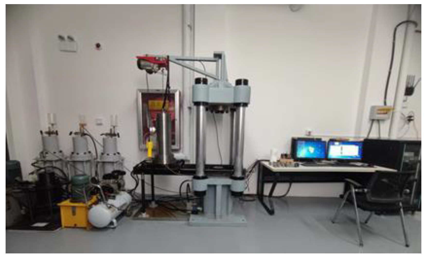
2.2. Experimental Method

In this study, the Changchun Zhantuo Triaxial Testing Machine (model TAW-1000) was employed to perform both monotonic and cyclic tests under both HTHP and ambient conditions (Figure 1). The equipment has a maximum axial pressure of 1000 KN, a maximum confining pressure of 100 MPa, and a maximum testing temperature of 160 °C. The axial failure stress (σ1) can be derived from Equation (1), and the elastic modulus (E) and poisson’s ratio can be derived from Equations (2) and (3), respectively.
σ 1 = F max A
E = Δ P ( 25 40 % ) Δ ε a ( 25 40 % )
u = Δ ε l ( 25 40 % ) Δ ε a ( 25 40 % )
where, Fmax is the maximum axial failure load of well cement, N; A is the compression area of cylindrical samples, mm2; ΔP(25–40%), Δεa(25–40%), and Δεl(25–40%) are the changes in stress, axial strain, and lateral strain, respectively, corresponding to the linear portion of the stress–strain curve, i.e., approximately 25–40% of ultimate strength.
It should be noted that all triaxial tests were performed under undrained conditions, where pore water was not allowed to flow out. The cyclic loading test program is illustrated in Figure 2, in which the axial load is alternately cycled within a predefined range between the upper and lower load limits. In this study, the lower limit of cyclic loading was set to 10% ultimate strength (0.1 P), while the upper limit was set to 0.9 P, 0.8 P, 0.7 P, and 0.6 P. The ultimate strength is the maximum deviatoric stress on the stress–strain curve (i.e., the failure point) for confined tests. A loading rate of 100 N/s was employed for the investigation. In this study, three specimens were used in the ambient monotonic loading test, and one sample was used for each confining pressure in the high temperature monotonic loading test. In the cyclic loading test, one specimen was used for each test condition. The use of only one sample for a triaxial test is justified by the excellent reproducibility of the test results, as indicated by our previous study [24].

3. Experimental Results

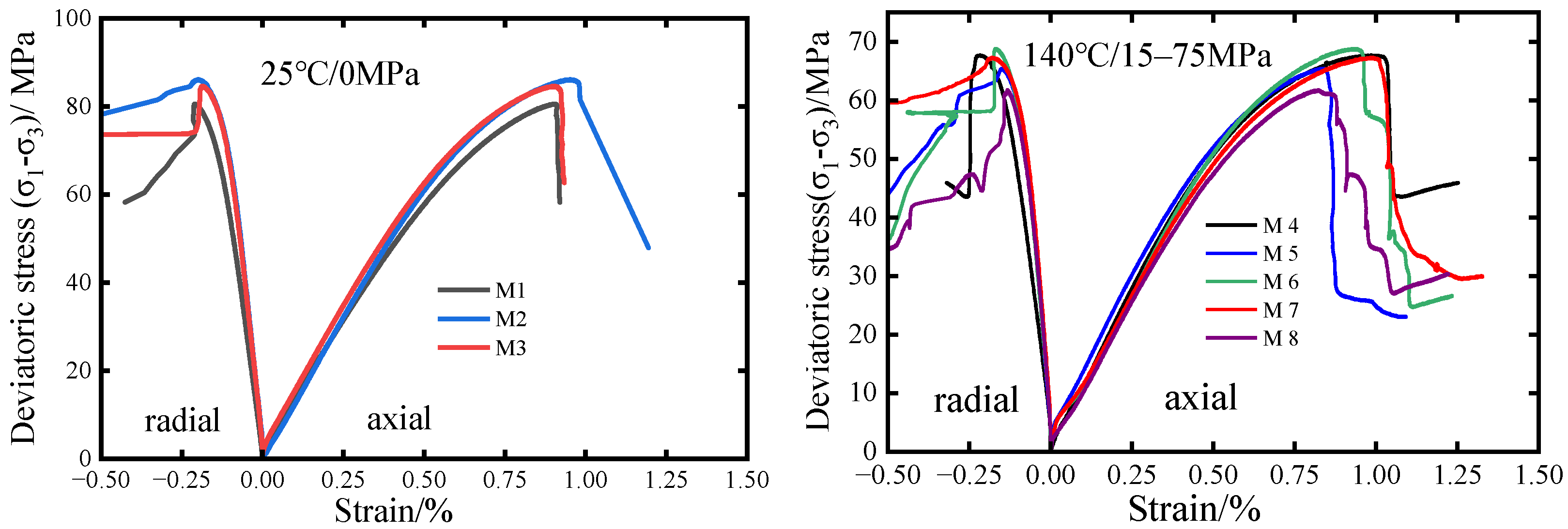
3.1. Monotonic Loading Test Analysis

Under the same effective confining stress, it is well known that increasing testing temperatures can cause reductions in the compressive strengths of rock and well cement [24]. The mechanical properties of well cement subjected to monotonic loading tests are presented in Table 2. It is observed that the compressive strength and elastic modulus of well cement obtained under HTHP test conditions decreased by 21% and 14%, respectively, when compared to those obtained under ambient test conditions. The decreases in mechanical properties can be mainly attributed to the high testing temperature, as the test results obtained at various confining pressures are similar. In other words, confining pressure appeared to have very little influence on the mechanical properties of the well cement. This may be due to the fact that all tests were performed under undrained conditions. Similar results have been reported by other studies [25,26,27]. During undrained tests, the pore pressure of saturated well cement will increase with increasing confining pressure, reducing the effective confining stress on the sample. Under confined testing conditions, increasing temperatures could also lead to increases in pore pressure due to the thermal expansion effect. The deformation characteristics of well cement, represented by stress–strain curves, are depicted in Figure 3. It can be observed that the testing environment also affected the stress–strain curve characteristics of well cement. Under the ambient test conditions, the well cement completely lost its ability to resist external loads after stress reached its ultimate compressive strength. However, under the HTHP testing condition, the oil-well cement can still sustain external load after the compressive strength is reached, with residual strengths ranging from 20 MPa to 45 MPa.

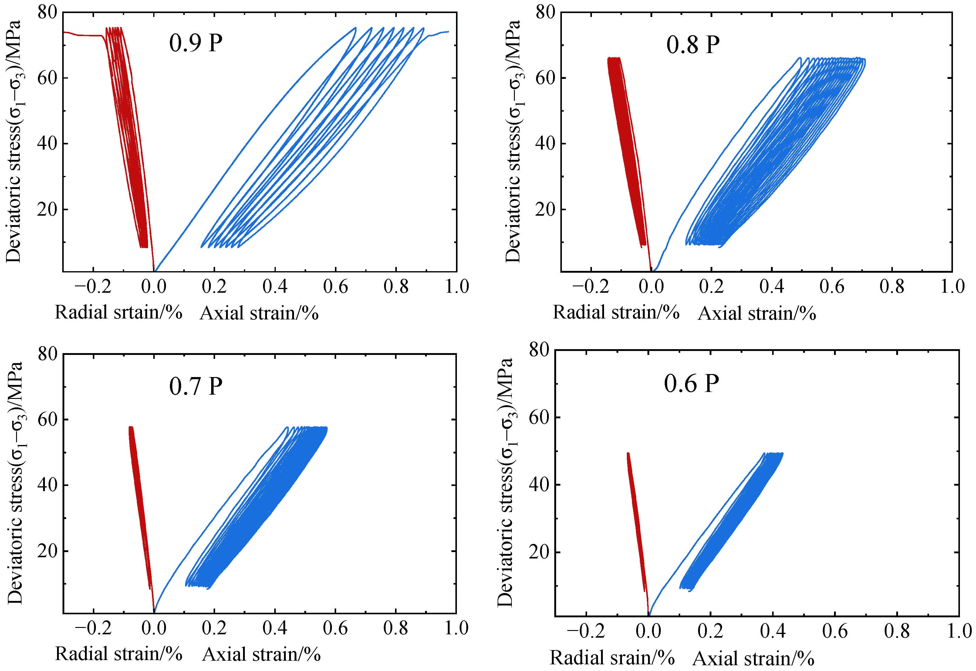
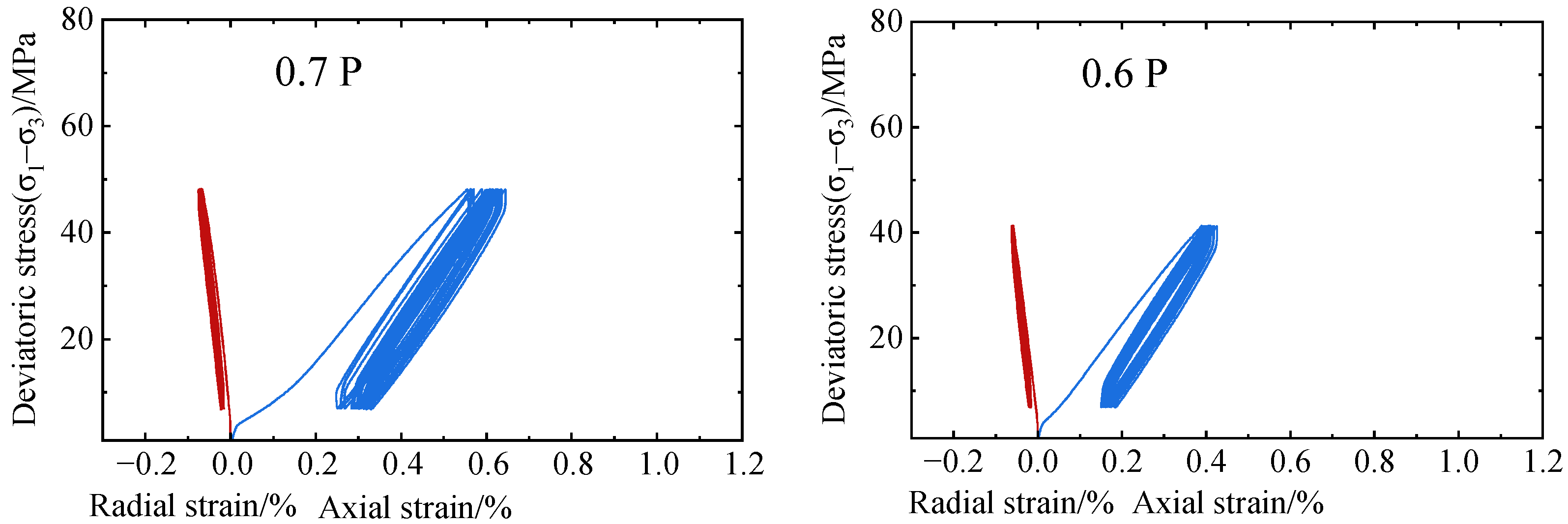
3.2. The Mechanical Properties of Well Cement during Cyclic Loading

Previous studies have shown that materials like rocks and cementitious can experience fatigue failure under cyclic loading conditions [28,29]. The stress–strain curves of oil-well cement during cyclic loading are depicted in Figure 4 and Figure 5. It can be seen that oil-well cement tested at ambient conditions experienced fatigue failure within 20 cycles when the upper limit of cyclic loading was set at 0.9 P. However, under HTHP test conditions, all well cement samples completed 20 loading and unloading cycles without failure. The deformation characteristics of well cement were significantly influenced by the intensity of cyclic loading. As the intensity of cyclic loading increased, the hysteresis loops in the stress–strain curves became wider and more dispersed, and the increases in both total strain and cycle number became more prominent. Interestingly, the testing conditions also affected the shape of the hysteresis loops. When subjected to HTHP conditions, the hysteresis loop became larger and took on a diamond shape compared to the oval shape observed under ambient conditions. As hardened oil-well cement contains micropores and micro-cracks as natural defects, its loading and unloading processes generally involve the opening and closing of these defects. While these defects can be readily closed during loading, their opening takes time; hence, strain recovery lags behind stress during unloading, causing hysteresis. The observed differences between HTHP and ambient test conditions can be explained as follows: under triaxial testing conditions (i.e., HTHP conditions), the defects in cement are still compacted by confining pressure during unloading, and their recovery takes even more time, leading to stronger strain recovery lag and bigger stress–strain hysteresis.
The deformation characteristics of the cement sheath can reflect the sealing performance. When significant irreversible deformation occurs, micro-annulus will be formed between cement–casing interfaces or cement-formation interfaces in the wellbore annulus. Figure 6 demonstrates the strain evolution of well cement with increasing loading cycles. Total strain represents the strain value of well cement under the maximum load during each loading cycle, while plastic strain represents the strain value under the minimum load within each cycle. Elastic strain was calculated as the difference between the total strain and the plastic strain. Obviously, both the maximum strain and plastic strain of well cement increased significantly as the upper limit of cyclic loading intensity increased.
Previous research has shown that the primary cause of fatigue failure of cement-based materials was the accumulation of plastic strain with increasing loading cycles [4,30,31]. As shown in Figure 6, when the intensity of cyclic loading was low (e.g., 0.6 P and 0.7 P), the accumulation of plastic strain with cycle number increased extremely slowly under both ambient and HTHP conditions. However, when the intensity of cyclic loading was high (e.g., 0.8 P and 0.9 P), the accumulation of plastic strain increased quickly. At the same loading intensity of 0.9 P, the sample tested under ambient conditions failed with a relatively small increase in plastic strain (total amount of increase was 0.279 from the 1st cycle to failure), whereas the samples tested under HTHP conditions experienced a large increase in plastic strain without failure (total amount of increase was 0.6711 from the 1st cycle to the 20th cycle). Additionally, the initial value of plastic strain (i.e., after the 1st cycle) under the HTHP condition was much greater than that under the ambient condition, which is consistent with the results in [32]. Under the HTHP test condition, oil-well cement was more prone to generating micro-cracks, and hence the cement was more compactable during initial loading. However, under the HTHP test condition, well cement can also sustain a large number of micro-cracks before large fracture surfaces develop (i.e., before complete failure occurs). In contrast, apparent increases in elastic strain with cycle were only observed at high loading intensities (i.e., at 0.8 P and 0.9 P) under the ambient test condition. At all other test conditions, elastic strain remained relatively stable throughout the cyclic testing periods. The initial value of the elastic strain under the HTHP test condition was smaller than that under the ambient condition.
The modulus of well cement is a crucial parameter that characterizes its ability to resist deformation under external loads. Since well cement is not an ideally linear-elastic material, its ability to resist deformation during cyclic loading can be described using the loading and unloading secant modulus [28,31]. The loading secant modulus is defined as the slope of the line connecting the lower limit stress point and the upper limit stress point on the loading curve of each cycle, while the unloading secant modulus corresponds to the slope of the line connecting the upper limit stress point and the lower limit stress point on the unloading curve. Figure 7 illustrates the evolution of the loading and unloading secant moduli of well cement under different testing environments. Due to the presence of initial natural defects in the material, such as micropores and micro-cracks, the loading secant modulus experienced a sharp increase during the first to second loading cycles, reflecting the compaction of these initial defects. Subsequently, under ambient test condition, the loading secant modulus decreased as the number of loading cycles increased and higher cyclic loading intensity resulted in a faster reduction in secant modulus. This suggests that high cyclic loading intensity negatively impacts the internal structure of well cement, causing the formation of additional microscopic defects and ultimately resulting in lower secant moduli. Conversely, under the HTHP test condition, the loading secant modulus remained relatively stable from the second cycle to the twentieth cycle. The unloading secant modulus exhibited similar variation patterns as the loading secant modulus. The unloading secant moduli were higher than the loading secant moduli at ambient test conditions, whereas the unloading secant moduli were approximately equal to the loading secant moduli at HTHP test conditions.

3.3. The Mechanical Properties of Well Cement after Cyclic Loading

After 20 cycles of cyclic loading tests, the well cement samples that had not failed were fully unloaded and further subjected to monotonic loading tests. Table 3 summarizes the mechanical properties obtained from the monotonic loading test. It should be noted that, due to fatigue failure during the cyclic loading test, sample C1 was not listed in Table 3. After 20 cycles of cyclic loading, the average ultimate compressive strengths of well cement subjected to ambient and HTHP conditions were 81.14 ± 2.45 MPa and 66.20 ± 2.38 MPa, respectively. These values were nearly identical to those obtained without cyclic loading (see Table 2), indicating that the compressive strength of the well cement was hardly affected by the cyclic loading process. Additionally, the elastic modulus of well cement after cycling exhibited a decreasing trend with an increasing intensity of cyclic loading. Specifically, under ambient test conditions, the elastic modulus decreased by 20% with loading intensity increasing from 0.6 P to 0.8 P, while under HTHP test conditions, the elastic modulus decreased by 16% with loading intensity increasing from 0.6 P to 0.9 P. The observed phenomenon could be attributed to the compaction of initial natural defects at low loading intensities (leading to enhanced elastic modulus) and the generation of new microscopic defects at high loading intensities (leading to reduced elastic modulus).

3.4. Energy Analysis during Cyclic Loading

During the cyclic loading and unloading process, well cement undergoes energy input, accumulation, and dissipation. As the well cement was axially compressed during the loading phase, a portion of the input energy was stored as elastic energy within the material, while the remaining energy was converted into dissipative or dissipated energy, which is associated with the closing of existing cracks as well as the generation of new cracks, often causing irreversible deformation. Notably, elastic energy is reversible and completely released during the unloading phase, while dissipative energy is irreversible. Figure 8 shows the energy evolution of well cement under cyclic loading. U represents the total energy input to the well cement from the external environment, which is equal to the area enclosed by the loading stress–strain curve and the horizontal (strain) axis. Ue denotes the reversable elastic energy, corresponding to the area enclosed by the unloading stress–strain curve and the horizontal (strain) axis. Ud represents the dissipated energy, which is the difference between U and Ue. Under the ambient conditions, the three forms of energy were observed to increase slightly with increasing cycle number at high loading intensities but remained relatively stable at low loading intensities. Under the HTHP test condition, there were very few variations in the three forms of energy with the number of cycles, regardless of the cyclic loading intensity.
Figure 9 illustrates the proportion of dissipated energy in total input energy for well cement and its variations with the loading intensity and cycle number under different testing environments. When the intensity of cyclic loading was high (0.9 P), a significant portion of the total energy absorbed by the well cement was converted into dissipated energy. With decreasing cyclic loading intensity, the proportion of dissipated energy in total energy was also reduced. The maximum energy input occurred during the first loading cycle, and the proportion of dissipated energy in total energy was also significantly higher during that cycle. It is obvious that, for all loading intensities, the proportion of dissipated energy in total input energy is significantly higher at the HTHP test condition, compared with that at the ambient test condition.

3.5. Fatigue Failure Model of Well Cement under Alternating Stress

Extensive prior research has established [4,30,32] that the strain evolution of cement-based materials as a function of normalized fatigue cycle count (or loading time) can be categorized into three distinct stages, as illustrated in Figure 10. These stages are: (I) A rapid increase in strain with loading cycles, which can be attributed to the compaction effects of initial natural defects; (II) a linear increase in strain with loading cycles, reflecting the cumulative damage inflicted by fatigue loading on the material; and (III) a rapid increase in strain with loading cycles, indicative of unstable crack propagation within the material prior to failure. During the second stage, the rate of strain evolution with normalized cycle count (or time) remained largely unaffected by loading intensity and loading rate [4,30,32]. Consequently, the rate of strain change within the second stage can be utilized to predict the fatigue life (NF) of well cement, as demonstrated in Equation (1).
ln ε · = ln f + ln ε a ε b a b ln N F
where, ε ˙ I I represents the rate of strain change with time during the second stage of strain evolution; f denotes the loading frequency (Hz); NF represents the fatigue life, which is the maximum number of cycles the test sample can sustain before failure; a and b correspond to the normalized loading cycle’s initial (Na/NF) and final (Nb/NF) points within the second stage, respectively; ε I I a and ε I I b represent the well cement strain values at points a and b. These strain values can be expressed as total strain or plastic strain, provided that they correspond to the strain value used in ε ˙ I I . It should be noted that the division of the three different stages may not be obvious with short fatigue lives, especially when the fatigue life is less than 10 cycles, but the rate of strain evolution during the middle stage can still be employed to represent the strain rate evolution during the second stage. Utilizing the relationship between loading frequency and loading period, the rate of strain evolution with loading cycles can be correlated with the rate of strain evolution with time. Assume ε I I n is the rate of strain evolution with cycle number during the second stage of strain evolution. By combining Equations (4) and (5), Equation (6) can be obtained:
ε n = ε ( t × f ) = 1 f × ε t = 1 f × ε ·
ln ε n = ln ε a ε b a b ln N F
Therefore, the rate of well cement strain evolution with the loading cycle in the second stage can be employed to predict its fatigue life. Note that the key parameter ε I I a ε I I b a b remains constant regardless of the intensity of cyclic loading and can be obtained by performing a cyclic test on a standard sample until failure. In this study, samples M1 and M5 were selected as the standard samples to calculate such key parameters for ambient and HTHP conditions, respectively. It should be noted that, because sample M5 did not fail during the cyclic loading, its test results can only be used to estimate the conservative values of fatigue life (i.e., the real fatigue life should be higher than the estimated values). Table 4 and Table 5 show the fatigue strength predicted by the mathematical model. It can be seen that the fatigue life of well cement under HTHP testing conditions was much higher than that under ambient testing conditions. When subjected to a cyclic loading intensity of 0.6 P, well cement exhibited minimal fatigue damage with a strain evolution rate close to zero, suggesting that 60% of ultimate strength is close to the fatigue limit, below which no fatigue failure can occur.

4. Conclusions

(1)
The mechanical properties of well cement are significantly influenced by the testing environment. Specifically, increasing the testing temperature from 25 °C to 140 °C reduces the compressive strength and elastic modulus of well cement by 21% and 14%, respectively. However, the confining pressure has almost no effect on the mechanical properties or stress–strain curves of well cement during undrained tests at high temperatures, possibly due to increased pore pressure with increasing confining pressure.
(2)
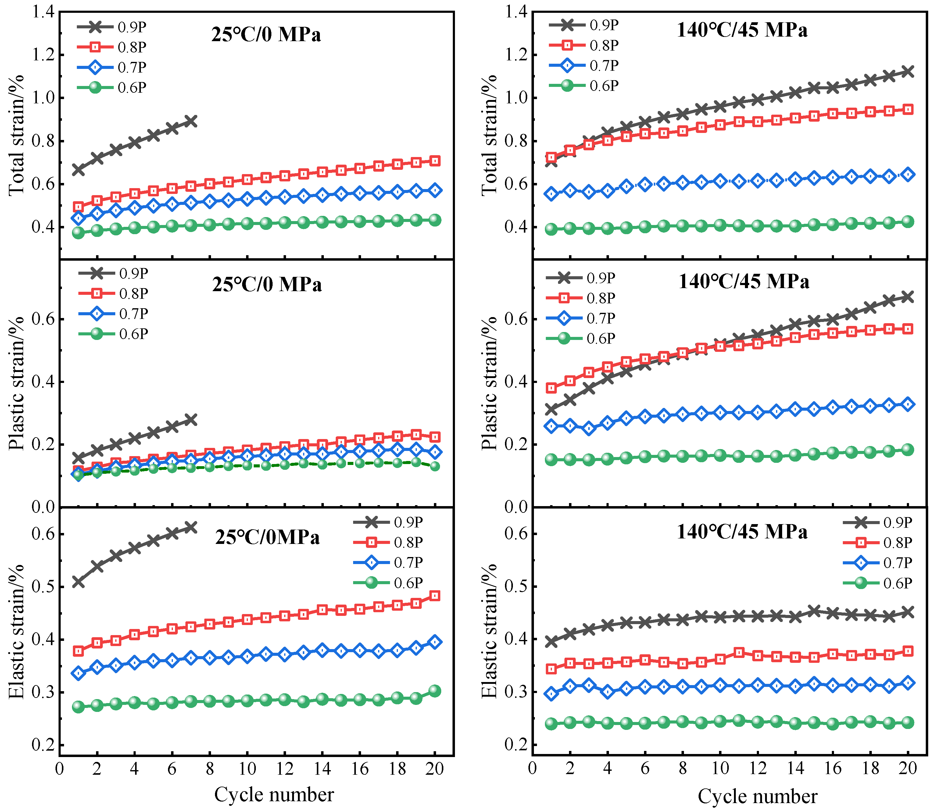
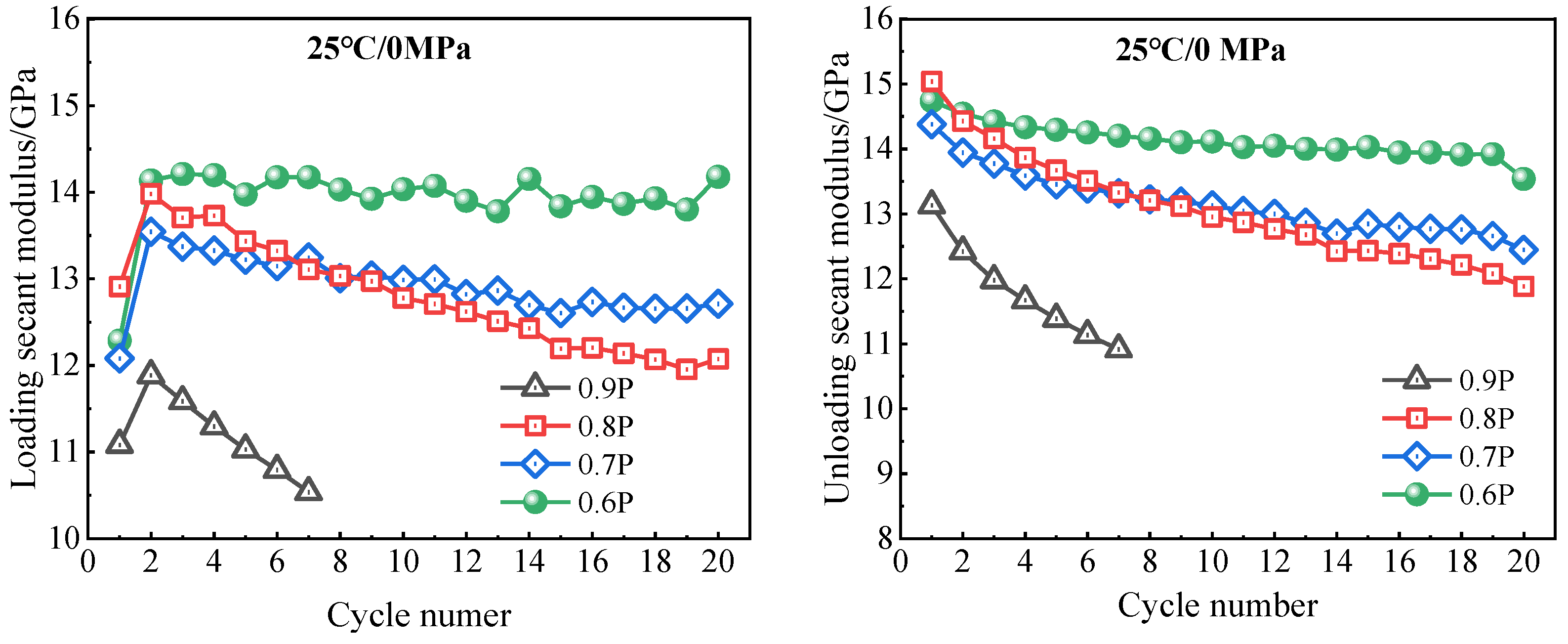
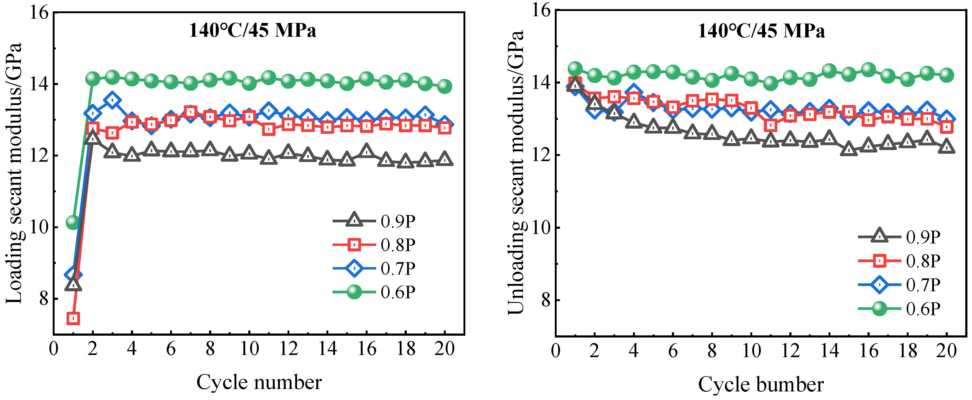
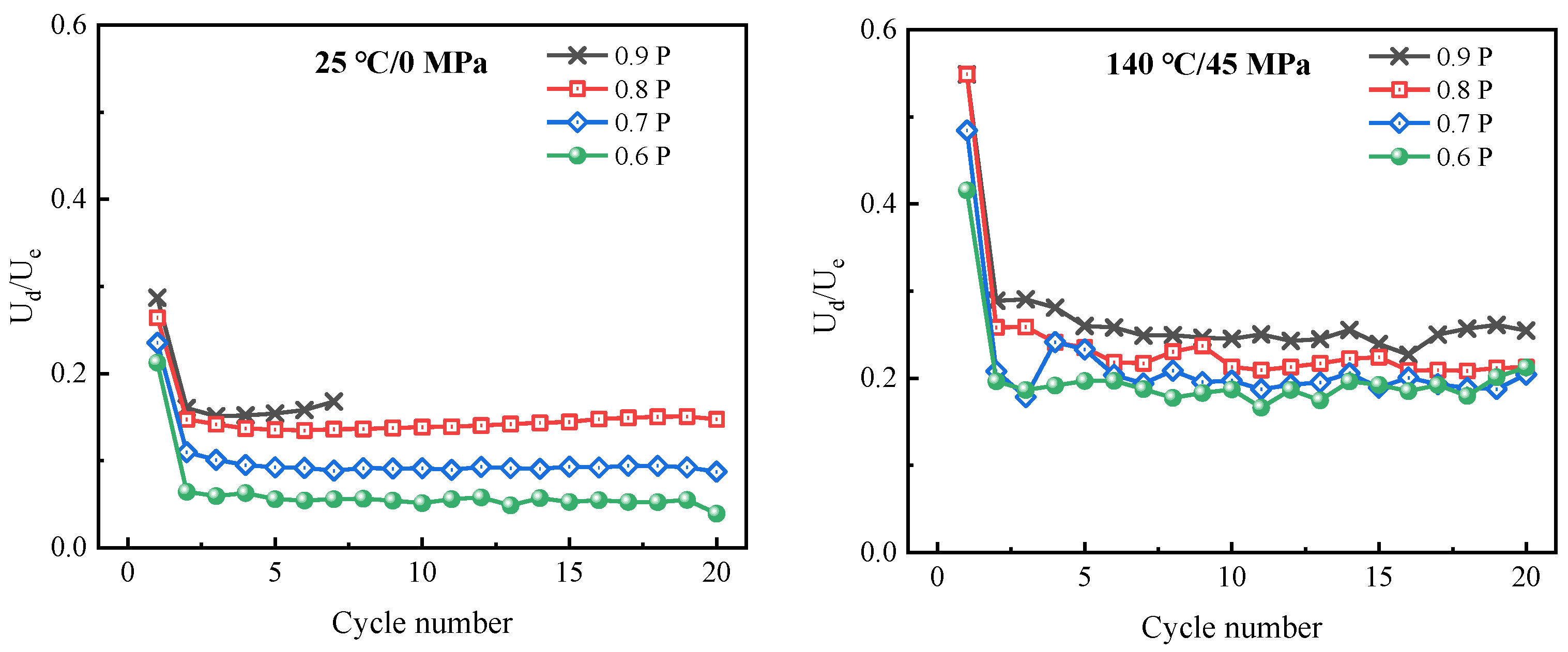
The deformation and mechanical properties of well cement are influenced by the cyclic loading intensity and cycle number. Under HTHP conditions, well cement exhibits more pronounced strain hysteresis and greater plastic strain, which leads to a higher conversion rate of input energy into dissipated energy. The secant modulus of well cement decreases with increasing loading intensity at all test conditions and also decreases with increasing cycle number, especially under ambient testing conditions with high loading intensity.
(3)
Samples that can sustain 20 cycles of cyclic loading without failure exhibit similar ultimate compressive strength as the pristine sample not subjected to cyclic loading. However, the elastic modulus of cyclically loaded samples may decrease when the cyclic loading intensity is high.
(4)
Well cement has a longer fatigue life when subjected to HTHP testing conditions compared to that tested under ambient conditions. The fatigue life of well cement increases significantly with a decrease in loading intensity and can be predicted based on the plastic strain evolution rate. At 0.6 P loading intensity (60% of ultimate strength), well cement hardly experiences any fatigue damage.

Author Contributions

Data curation, formal analysis, writing—original draft, Z.Z.; Data curation, formal analysis, Z.Y.; Investigation, S.Y., Y.L., L.Y. and K.L.; Funding acquisition, supervision, writing—review & editing, X.P.; Funding acquisition, investigation, J.S. All authors have read and agreed to the published version of the manuscript.

Funding

Financial support comes from the National Natural Science Foundation of China (Basic Science Center Project, Grant No. 52288101) as well as from China University of Petroleum (East China) (Grant No. 23CX05001A).

Data Availability Statement

Data are contained within the article.

Conflicts of Interest

Jinsheng Sun is an employee of CNPC Engineering Technology R&D Company Limited. Zhongtao Yuan, Sutao Ye and Lvchao Yang are funded by Petro China Tarim Oilfield Company. The authors declare no conflicts of interest.

References

  1. Caa, M.; Cyran, K.; Kowalski, M. Influence of the Anhydrite Interbeds on a Stability of the Storage Caverns in the Mechelinki Salt Deposit (Northern Poland). Arch. Min. Sci. 2018, 63, 1007–1025. [Google Scholar]
  2. Xie, L.; Zhang, H.; Li, H. Accident Analysis and Risk Identification of Underground Gas Storage Tanks with Exhausted Oil and Gas Reservoirs. Nat. Gas Ind. 2009, 29, 116–119. [Google Scholar]
  3. Shu, G.; Liu, J.; Feng, F.; Zhang, Y.; Zhou, L.; Chen, H.; Wang, C. Experimental study on failure mechanism of cement sheath in injection production well of gas storage. Drill. Complet. Fluids 2020, 37, 507–511+520. [Google Scholar]
  4. Pang, X.; Darbe, R.; Ravi, K.; Meyer, C. Low-cycle fatigue of oil well cements in compression. ACI Mater. J. 2012, 109, 185–194. [Google Scholar]
  5. Ma, X.; Zheng, D.; Wei, G.; Ding, G.; Zheng, S. Development directions of major scientific theories and technologies for underground gas storage. Nat. Gas Ind. 2022, 42, 93–99. [Google Scholar]
  6. Ma, Y.; Cai, X.; Yun, L.; Li, Z.; Li, H.; Deng, S.; Zhao, P. Practice and theoretical and technical progress in exploration and development of Shunbei ultra-deep carbonate oil and gas field, Tarim Basin, NW China. Pet. Explor. Dev. 2022, 49, 1–17. [Google Scholar] [CrossRef]
  7. Azin, R.; Nasiri, A.; Entezari, J. Underground Gas Storage in a Partially Depleted Gas Reservoir. Oil Gas Sci. Technol.-Rev. IFP 2008, 63, 691–703. [Google Scholar] [CrossRef]
  8. Yuan, G.; Xie, Y.; Jin, G.; Ban, F. Present State of Underground Storage and Developmemt Trends in Engineering Technologies at Home and Abroad. Pet. Drill. Tech. 2017, 45, 8–14. [Google Scholar]
  9. Matsumoto, T.; Suthiwarapirak, P.; Kanda, T. Mechanisms of Multiple Cracking and Fracture of DFRCC under Fatigue Flexure. J. Adv. Concr. Technol. 2003, 1, 299–306. [Google Scholar] [CrossRef]
  10. Liu, W.; Xu, S.; Li, Q. Study of Flexural life of ultra-high toughness cementitious composites under constant ampliture cyclic loading. J. Build. Struct. 2012, 33, 119–127. [Google Scholar]
  11. Chu, W.; Shen, J.; Yang, Y.; Li, Y.; Gao, D. Calculation of micro-annulus size in casing-cement sheath-formation system under continuous internal casing pressure change. Pet. Explor. Dev. 2015, 42, 414–421. [Google Scholar] [CrossRef]
  12. Liu, W.; Yu, B.; Deng, J. Analytical method for evaluating stress field in casing-cement-formation system of oil/gas wells. Appl. Math. Mech. 2017, 38, 1273–1294. [Google Scholar] [CrossRef]
  13. Goodwin, K.; Crook, R. Cement sheath stress failure SPE drilling engineering. SPE Drill. Eng. 1992, 7, 291–296. [Google Scholar] [CrossRef]
  14. Yuan, Z.; Teodoriu, C.; Schubert, J. Low cycle cement fatigue experimental study and the effect on HPHT well integrity. J. Pet. Sci. Eng. 2013, 105, 84–90. [Google Scholar] [CrossRef]
  15. Shadravan, A.; Schubert, J.; Amani, M.; Teodoriu, C. Using fatigue-failure envelope for cement-sheath-integrity evaluation. SPE Drill. Complet. 2015, 30, 68–75. [Google Scholar] [CrossRef]
  16. Deng, K.; Yuan, Y.; Hao, Y.; Li, Z.; Lin, Y. Experimental study on the integrity of casing-cement sheath in shale gas wells under pressure and temperature cycle loading. J. Pet. Sci. Eng. 2020, 195, 107548. [Google Scholar]
  17. Liu, J.; Li, J.; Zhang, Y.; Zhu, T.; Yang, S.; Li, Y. Analysis of energy characteristics and deformation parameters of rock mass under cyclic loading. Chin. J. Rock Mech. Eng. 2010, 29, 3505–3513. [Google Scholar]
  18. You, M.; Hua, A. Energy analysis of the failure process of rock specimens. Chin. J. Rock Mech. Eng. 2002, 21, 778–781. [Google Scholar]
  19. Guo, Y.; Zhao, K.; Sun, G.; Yang, C.; Ma, H.; Zhang, G. Experimental study of fatigue deformation and damage characteristics of salt rock under cyclic loading. Rock Soil Mech. 2011, 32, 1353–1359. [Google Scholar]
  20. Li, Z.; Wu, G.; Huang, T.; Liu, Y. Variation of energy and criteria for strength failure of shale under traixial cyclic loading. Chin. J. Rock Mech. Eng. 2018, 37, 662–670. [Google Scholar]
  21. Chen, L.; Wang, S.; Zhang, D. Research on impact energy dissipation characteristics of cement of coalbed methane wells based on SHPB test. Mater. Rep. 2021, 35, 232–237. [Google Scholar]
  22. Li, Y.; Xu, K.; Zhang, H.; Huang, S.; Yin, G.; Wang, Z.; Zeng, C. Special geological factors in drilling engineering of ultra-deep oil and gas reservoir in Tarim Baisn. China Pet. Explor. 2022, 27, 88. [Google Scholar]
  23. Zhang, Z.; Qin, J.; Pang, X.; Ma, Z.; Zhou, Y. Comparison of three different deconvolution methods for analyzing nanoindentation test data of hydrated cement past. Cement Concrete Comp. 2023, 138, 104990. [Google Scholar] [CrossRef]
  24. Li, H.; Pang, X.; Ghabezloo, S.; Zhang, J.; Shi, X.; Qin, J. Influence of testing temperature and pressure on the mechanical behavior of well cementing materials. J. Mater. Res. Technol. 2023, 26, 3992–4006. [Google Scholar] [CrossRef]
  25. Thiercelin, M.; Baumgarte, C.; Guillot, D. A soil mechanics approach to predict cement sheath behavior. In Proceedings of the SPE/ISRM Rock Mechanics in Petroleum Engineering, Trondheim, Norway, 8–10 July 1998. SPE-47375-MS. [Google Scholar]
  26. Lima, V.N.; Skadsem, H.J.; Beltrán-Jiménez, K.; Zhemchuzhnikov, A.; Velloso, R.Q.; Silva, F.d.A. Triaxial behavior of a stabilized and a highly porous oil well cement paste at different saturation and drainage conditions. J. Pet. Sci. Eng. 2022, 219, 111055. [Google Scholar] [CrossRef]
  27. Ghabezloo, S.; Sulem, J.; Guédon, S.; Martineau, F.; Saint-Marc, J. Poromechanical behaviour of hardened cement paste under isotropic loading. Cem. Concr. Res. 2008, 38, 1424–1437. [Google Scholar] [CrossRef]
  28. Song, Z.; Wang, C.; Zhao, Y.; Yu, Z.; Yang, Z.; Dang, W. Effect of frequency on rock’s mechanical responses under multi-level compressive cyclic loading: An experimental investigation. Bull. Eng. Geol. Environ. 2023, 82, 224. [Google Scholar] [CrossRef]
  29. Wang, L.; Zeng, Y.; Zhang, Q.; Xu, F.; Yang, C.; Guo, Y.; Tao, Q.; Liu, J. Experimental study on mechanical properties of oil well cement under high temperature. J. China Univ. Pet. 2018, 42, 88–95. [Google Scholar]
  30. Huang, B.-T.; Li, Q.-H.; Xu, S.-L.; Zhou, B.-M. Frequency effect on the compressive fatigue behavior of ultrahigh toughness cementitious composites: Experimental study and probabilistic analysis. J. Struct. Eng. 2017, 143, 04017073. [Google Scholar]
  31. Zhou, S.; Liu, R.; Zeng, H.; Zeng, Y.; Zhang, L.; Zhang, J.; Li, X. Mechanical characteristics of well cement under cyclic loading and its influence on the integrity of shale gas wellbores. Fuel 2019, 250, 132–143. [Google Scholar] [CrossRef]
  32. Huang, B.-T.; Li, Q.-H.; Xu, S.-L.; Liu, W.; Wang, H.-T. Fatigue deformation behavior and fiber failure mechanism of ultra-high toughness cementitious composites in compression. Mater. Des. 2018, 157, 457–468. [Google Scholar] [CrossRef]
Figure 1. TAW-1000 microelectromechanical hydraulic servo-controlled rock triaxial stress testing machine.
Energies 17 03856 g001
Figure 2. The cyclic loading test program of well cement.
Energies 17 03856 g002
Figure 3. Stress–strain curve of well cement under different testing conditions.
Energies 17 03856 g003
Figure 4. Deviatoric stress–strain curves of well cement tested under ambient condition (25 °C/0 MPa).
Energies 17 03856 g004
Figure 5. Deviatoric stress–strain curves of well cement tested under HTHP condition (140 °C/45 MPa).
Energies 17 03856 g005aEnergies 17 03856 g005b
Figure 6. Strain evolution of well cement with cycle number.
Energies 17 03856 g006
Figure 7. Loading and unloading secant modulus of well cement as a function of cycle number.
Energies 17 03856 g007aEnergies 17 03856 g007b
Figure 8. Variation of total input energy (U), elastic energy (Ue), and dissipated energy (Ud) with cycle number.
Energies 17 03856 g008
Figure 9. Ratio of dissipated energy to elastic energy as a function of cycle number.
Energies 17 03856 g009
Figure 10. Typical strain evolution pattern of cement-based materials as a function of normalized cycle number.
Energies 17 03856 g010
Table 1. The formula of cement slurry.
MaterialsDosage (%bwoc)
Aksu cement100
Anti-strength retrogression agent35
Silica fume4
Ductility-enhancement agent4
Suspending agent1
Dispersant1
Water52
Retarder3
Fluid loss additive3.5
Defoamer0.5
Table 2. Monotonic loading test results of well cement.
SpecimensTesting
Temperature/°C
Testing
Pressure/MPa
Compressive
Strength/MPa
Elastic
Modulus/GPa
Poisson’ Ratio
M125080.5411.700.212
M225086.1612.860.189
M325084.5912.640.188
Average83.73 ± 2.9212.4 ± 0.620.19 ± 0.014
M41401567.7010.960.251
M51403065.4510.890.155
M61404568.8011.110.178
M71406067.3310.250.151
M81407561.7710.240.154
Average66.21 ± 2.7610.69 ± 0.410.178 ± 0.04
Table 3. The mechanical properties of well cement after cycling.
SpecimensIntensity of
Cyclic Loading
Testing
Temperature/°C
Confining
Pressure
/MPa
Compressive Strength/MPaElastic
Modulus/GPa
C280%25077.979.89
C370%25083.9311.31
C460%25081.5312.67
C590%1004569.079.83
C680%1004567.0510.56
C770%1004566.1810.96
C860%1004562.5111.69
Table 4. Fatigue parameters of well cement under ambient condition (25 °C/0 MPa).
SamplesC1C2C3C4
Maximum loading intensity90%80%70%60%
Loading rate/(N/s)100100100100
Loading frequency f/Hz0.001590.001810.002090.00251
Loading period T/s629553478398
ε I I a ε I I b a b 0.1490.1490.1490.149
ε I I n 0.001960.005350.002150.00102
ε ˙ I I = ε I I t / 10−5·s−13.120.9670.4500.256
Fatigue life NF7.527 *68 *-
* Predicted fatigue life.
Table 5. Fatigue parameters of well cement under HTHP condition (140 °C/45 MPa).
SamplesC5C6C7C8
Maximum loading intensity90%80%70%60%
Loading rate/(N/s)100100100100
Loading frequency (f/Hz)0.001930.002190.002570.00308
Loading period (T/s)519458389324
ε I I a ε I I b a b 0.3020.3020.3020.302
ε I I n 0.01510.005400.00297-
ε ˙ I I = ε I I t / 10−5 s−12.8901.1790.763-
Fatigue life/NF>20>56 *>102 *-
* Predicted fatigue life.
Disclaimer/Publisher’s Note: The statements, opinions and data contained in all publications are solely those of the individual author(s) and contributor(s) and not of MDPI and/or the editor(s). MDPI and/or the editor(s) disclaim responsibility for any injury to people or property resulting from any ideas, methods, instructions or products referred to in the content.

