Review

Review of Compensation Topologies Power Converters Coil Structure and Architectures for Dynamic Wireless Charging System for Electric Vehicle

by
Narayanamoorthi Rajamanickam
1,*,
Yuvaraja Shanmugam
1,
Rahulkumar Jayaraman
1,
Jan Petrov
2,
Lukas Vavra
2 and
Radomir Gono
2
1
Wireless Charging Research Centre, Department of Electrical and Electronics Engineering, SRM Institute of Science and Technology, Kattankulathur, Chennai 603203, India
2
Faculty of Electrical Engineering and Computer Science, VSB-Technical University of Ostrava, 708-00 Ostrava, Czech Republic
*
Author to whom correspondence should be addressed.
Energies 2024, 17(15), 3858; https://doi.org/10.3390/en17153858
Submission received: 24 June 2024 / Revised: 16 July 2024 / Accepted: 31 July 2024 / Published: 5 August 2024

Abstract

:
The increasing demand for wireless power transfer (WPT) systems for electric vehicles (EVs) has necessitated advancements in charging solutions, with a particular focus on speed and efficiency. However, power transfer efficiency is the major concern in static and dynamic wireless charging (DWC) design. Design consideration and improvements in all functional units are necessary for an increase in overall efficiency of the system. Recently, different research works have been presented regarding DWC at the power converter, coil structure and compensators. This paper provides a comprehensive review of power converters incorporating high-order compensation topologies, demonstrating their benefits in enhancing the DWC of EVs. The review also delves into the coupling coil structure and magnetic material architecture, pivotal in enhancing power transfer efficiency and capability. Moreover, the high-order compensation topologies used to effectively mitigate low-frequency ripple, improve voltage regulation, and facilitate a more compact and portable design are discussed. Furthermore, optimal coupling and different techniques to achieve maximum power transfer efficiency are discussed to boost magnetic interactions, thereby reducing power loss. Finally, this paper highlights the essential role of these components in developing efficient and reliable DWC systems for EVs, emphasizing their contribution to achieving high-power transfer efficiency and stability.

1. Introduction

Wireless Power Transfer (WPT) technology has emerged as a promising solution for charging EVs without the need for physical connectors. This technology operates on the principle of magnetic resonance coupling, involving two coils: one connected to a power source and the other linked to the EV’s battery [1,2]. However, the efficiency of WPT systems is often limited by factors, such as coil distance, coupling coefficient, and frequency of operation [3]. To address these limitations and enhance the efficiency of WPT systems, power converters with high-order compensation topologies and dynamic coils with magnetic materials have been proposed [4]. The power converter is a critical component in WPT systems, converting AC power from the source into DC power necessary for charging the EV battery. The efficiency of the power converter significantly influences the overall effectiveness of the WPT system. High-order compensation topology is a technique employed to boost power converter efficiency by incorporating additional passive components into the converter circuit. These components help compensate for power losses during the conversion process, mitigating parasitic effects, and thereby enhancing power conversion efficiency [5].
The magnetic coil’s structure plays a critical role in improving the efficiency of WPT systems. These coils are designed to adjust the resonance frequency of the system in real-time based on the distance between the coils. By integrating magnetic materials into the design of magnetic coils, a high coupling coefficient is maintained, which in turn enhances system efficiency. Magnetic materials can increase the flux density of the coil, improving the coupling between the coils and thus the overall system performance. Research into the architecture of coupling coils with magnetic materials for WPT systems in EVs is ongoing. One approach involves using a multi-layered coil design with magnetic materials, such as ferrites or permalloy, which provide a larger surface area and increased coupling between the coils. Another approach utilizes metamaterial-based coil designs. Metamaterials, which are artificial materials with unique electromagnetic properties, can manipulate electromagnetic waves to increase the magnetic field intensity and reduce energy losses, thereby improving WPT efficiency. Selecting the appropriate magnetic material for WPT systems is crucial and depends on the operating frequency of the system. Commonly used materials include ferrites and permalloy, known for their high magnetic permeability, which concentrates the magnetic field and enhances coil coupling. Ferrites are more effective at low frequencies, while permalloy performs better at high frequencies.
In summary, the use of power converters with high-order compensation topologies and dynamic coils with magnetic materials holds significant potential for improving the efficiency of DWC for EV applications. As the demand for EVs continues to grow, developing effective WPT technology is essential for promoting sustainable practices and reducing dependence on fossil fuels. This paper explores these advanced techniques and their implications for enhancing WPT, aiming to contribute to the development of more efficient and effective wireless charging solutions for EVs. The rest of the paper is organized as follows: Section 1 covers a bibliometric analysis of the WPT system. Section 2 discusses power converter topologies for the WPT system. Section 3 examines compensation topologies for the WPT system. Section 4 delves into the magnetic coil structure. Section 6 focuses on magnetic materials for WPT. Finally, Section 7 addresses safety and health standards.

2. Methodology

2.1. Extraction of Bibliometric Data

The collection of data from published research was vital in achieving the research objectives, as it allowed for the identification of relevant academic publications to reference when making conclusions based on the study’s findings. SCOPUS was selected as the database for this research due to its extensive coverage of various studies, which exceeds that of other databases, such as WOS (Web of Science), Google Scholar (GS), PubMed, and many more [6]. For interdisciplinary study domains like the one discussed in the essay, SCOPUS is also a much better choice. Nonetheless, it should be underlined that materials generated in the engineering industry are similarly covered by both WOS and SCOPUS. In June 2024, a bibliometric search was conducted on the SCOPUS database to review published English language research on wireless power transfer (WPT) and electric vehicles (EVs) [7]. The search involved analyzing the co-occurrence of keywords, including “Energy Transfer”, “Magnetic Couplings”, “Inductive Power Transmission”, “Electric Vehicles”, “Wireless Charging”, “Inductive Power Transfer”, and “Inductive Couplings”, to locate relevant literature on the application of WPT in EVs [8]. Using integrated lists of targeted keywords and the Boolean logic operators AND and OR, 2163 records were retrieved. The search criteria on the SCOPUS database were configured to locate all appropriate records that included the selected keywords in the title, abstract, or specified keywords area. The search was restricted to articles published between 2011 and 2022, and only records related to the research topic were included.

2.2. Exclusion & Inclusion Criteria

During the initial keyword search, only articles that were relevant to the study were manually screened. This was accomplished by removing papers that did not directly relate to the application of wireless power transfer to electric vehicles. Figure 1 shows the distribution of bibliometric analysis documents. The following criteria were also used for inclusion:
(a)
In order to encompass all possible materials related to the topic, no specific document type (such as articles, books, lecture notes, etc.) was selected in the search.
(b)
The study period ran from 2011 to 2024. Any document produced during that time was considered. Any publication that fell outside of this range was disregarded.
(c)
The applicability of the abstracts’ descriptions of the document’s title and content. This was important in order to remove any documents that had no bearing on the study’s subject.

2.3. Scientometric Study

Co-occurrence, co-authorship, co-citation, and citation were evaluated using scientometric metrics (units of measure). In the co-occurrence research, units of measurement included keywords, nations, and co-authors [9]. Co-authorship used authors, nations, and organizations as the measuring units. Co-citations were measured in terms of authors and sources. The use of authors, papers, organizations, and sources was examined in the analysis of citations. Using network visualizations and density maps, the intellectual topography was mapped.

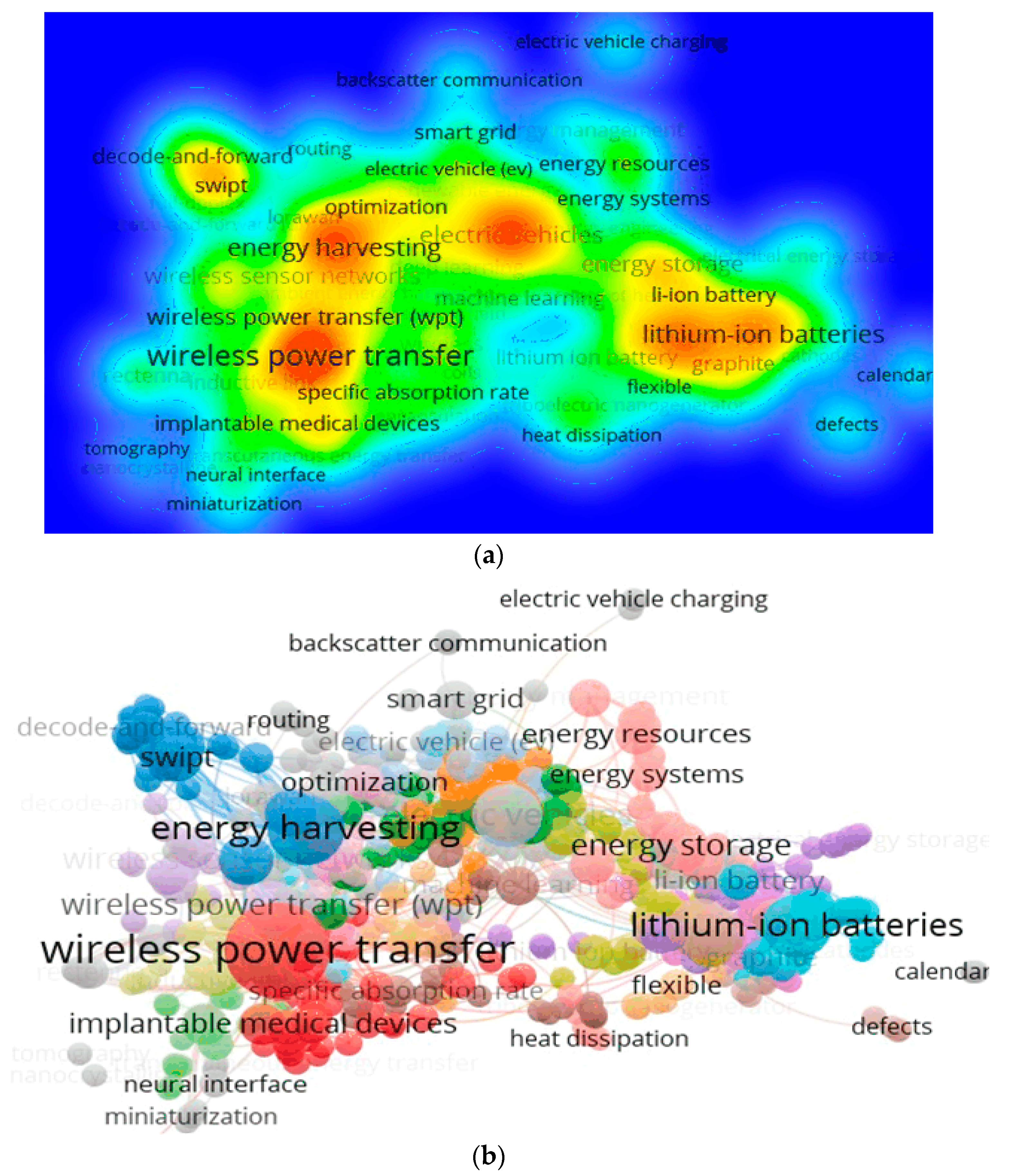
2.4. Keyword Co-Occurrence Study

The choice of keywords is crucial in reflecting the essence and scope of research in any given field. To establish and visualize the knowledge domain between WPT and EVs, this study utilized VOSviewer1.6.20 to analyze co-occurrence data for selected terms. The fractional computation method was used to weigh the links, hierarchically organizing the weight of each link [10]. The resulting term network visualization presented the findings of the bibliometric analysis, where the distance between two nodes indicated the intensity of their association. A greater distance between two nodes indicated a weaker association. To ensure the best clustering, a threshold was set to include only nodes that appeared at least five times, resulting in 698 out of 8053 entries meeting the criteria. The diagram in Figure 2 illustrates a network of co-occurring terms that contains eight groups of related terms, 30,876 connections between these terms, and a combined strength of 6829 for all of the connections.
Keyword co-occurrence networks offer a stationary depiction of the topic and do not account for any alterations that may occur over time. However, VOSviewer was used to display nodes according to the typical year that the term was used in the literature, showing a decline in the development of WPT applications in the EV sector in recent years. General terms, such as “inductive power transmission”, “wireless charging”, “electric power systems”, and “electric cars”, were popular around 2018, possibly due to research focus or saturation [11]. The focus of recent studies appears to have shifted from exploring the potential of different wireless power transfer methods to addressing specific concerns, such as inductive power transfer and electromagnetic shielding for safety. This is evident from the emergence of research topics, such as “object detection” and “shielding efficacy”, which suggest a change in research priorities. Only a few innovative techniques, like “compensation topology” or “internet of things”, stood out.

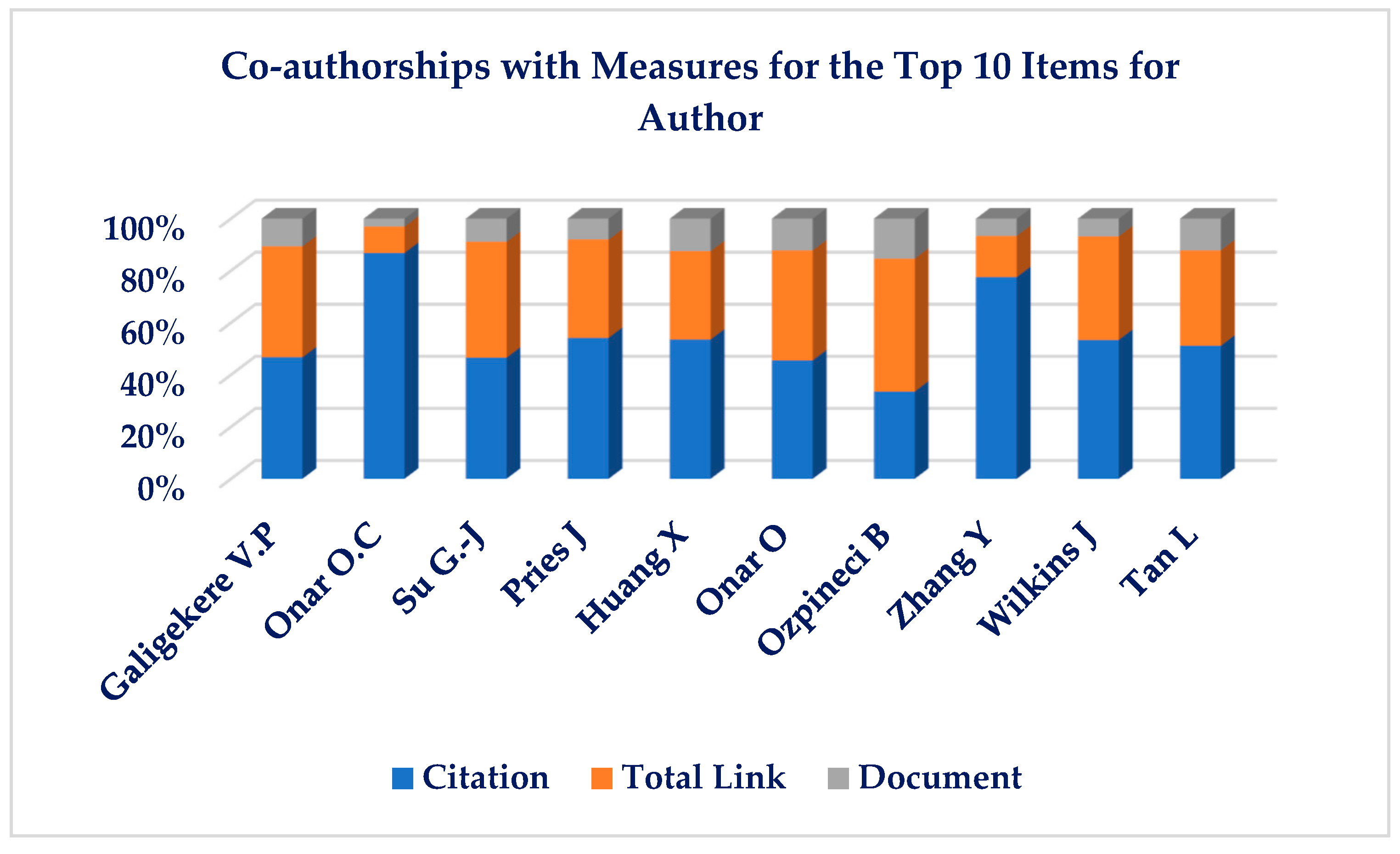
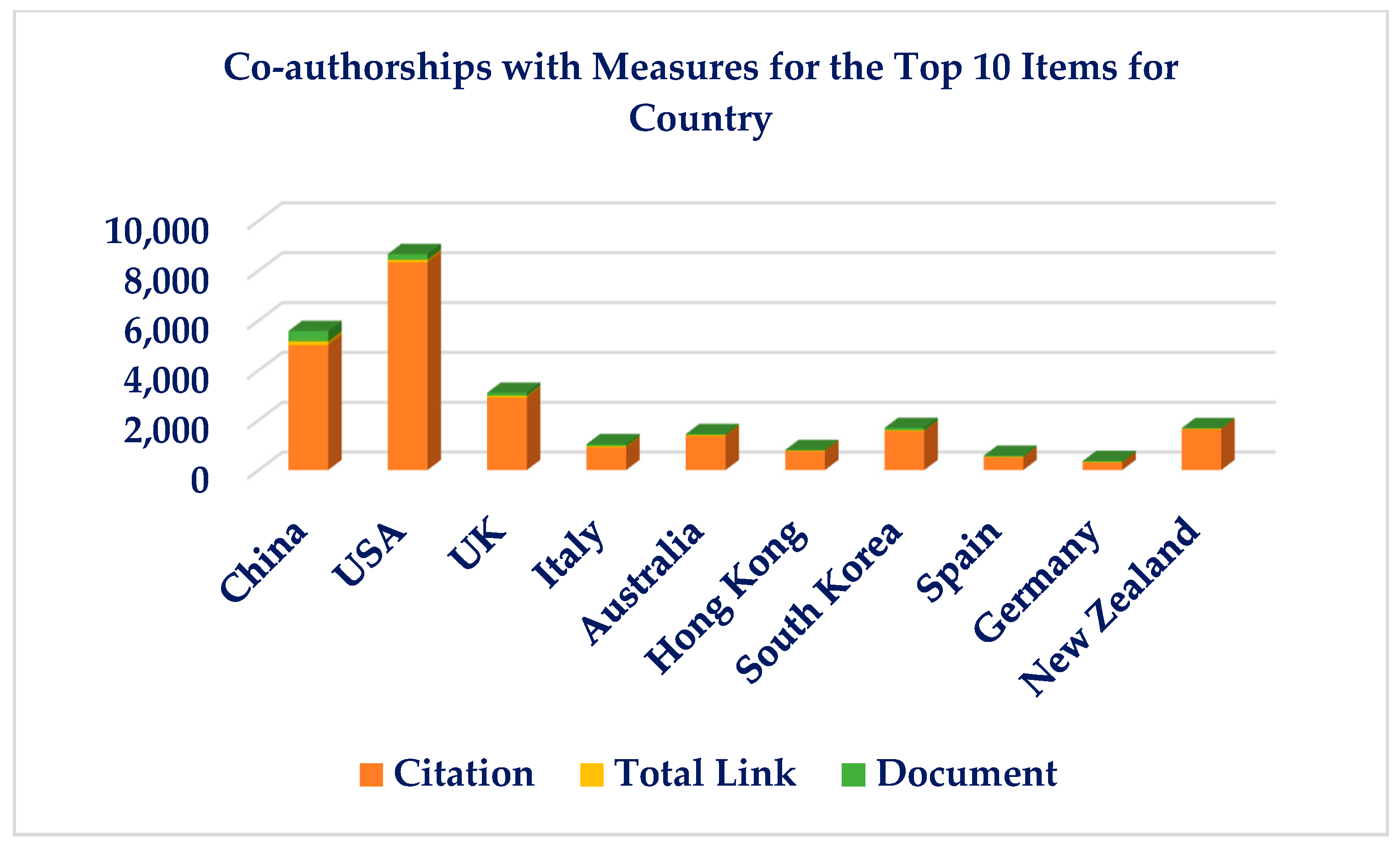
2.5. Analysis of Author, Country, and Organization Co-Authorship

The bibliographic information available in publications provides details on authors, their affiliations, and countries of origin, which can be used to identify top scholars and promote research collaborations. VOSviewer can be used to construct co-authorship networks and analyze scientific data to visualize knowledge domains. Some frequently cited authors, such as C.C. Mi, did not collaborate frequently with other writers or publish much material, while authors with fewer citations, such as V.P. Galigekere, had strong links, as shown in Figure 2 and Figure 3 [12]. The distribution of publications on WPT uses in EVs was analyzed by constructing a network of research contributions from various nations. The publications in the area benefited greatly from the contributions of the US, China, UK, Italy, and Australia. The engagement between academic institutions and organizations on challenges related to this area of study was found to be unusual, and increased collaboration across research institutes is needed to produce more valuable work. Table 1 shows the list of co-authorships with measures for the top 10 Items for organization. Figure 4 shows the general layout structure of keyword search analysis.

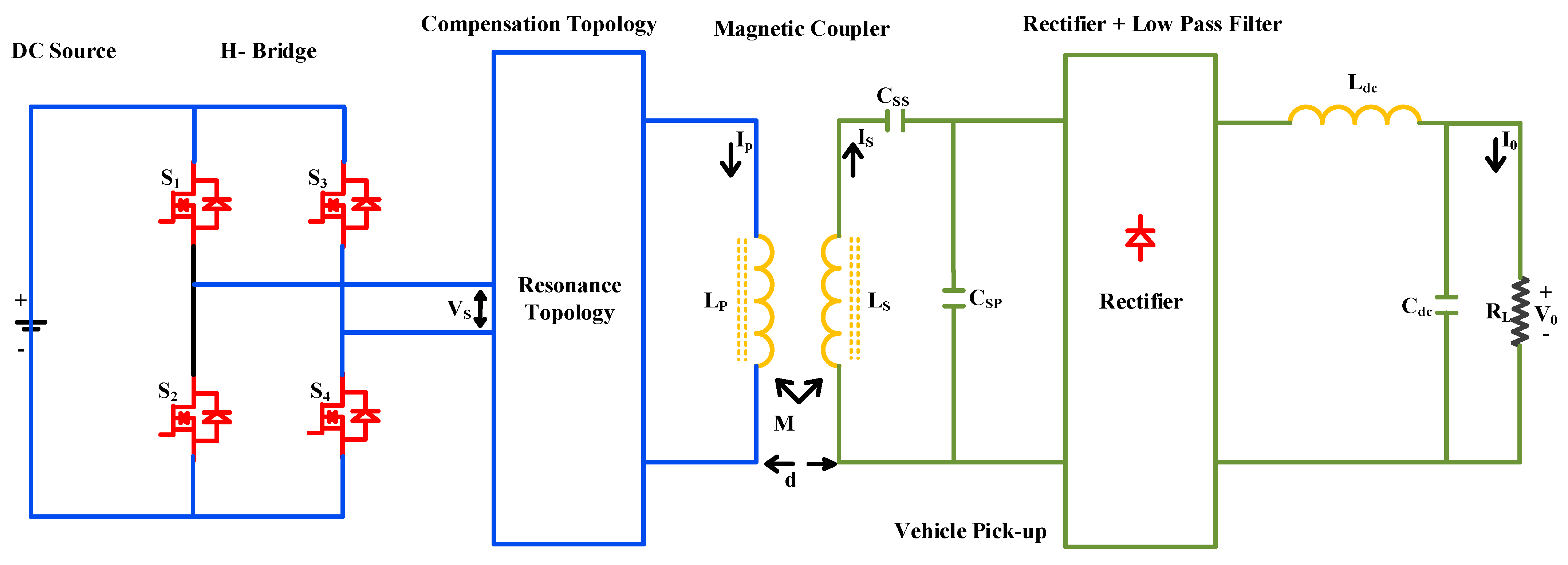
3. Power Converter for EVs in Dynamic Wireless Charging

Power converters for Dy need further improvement to enhance energy transfer efficiency and achieve high-power density [13,14]. An uncontrolled rectifier connects the AC power source via filter, which then interfaces with the inverter and resonance circuit and an inductive coil [15]. Secondary side rectifiers can be either regulated or unregulated based on the need for power flow regulation [16,17]. Before connecting the load, an unregulated bridge rectifier, filter, and secondary pickup coils are attached. Some contemporary works employ a boost converter to increase the quality factor and control power supply before the load [18,19]. Resonance is essential in WPT, as it determines the magnitude, frequency, and phase of the current waveform. Various power conversion topologies, their operating environments, and benefits are described in detail, considering misalignment, operating frequency, and load changes [20,21]. The high-frequency inverter generates high-frequency magnetic waves in the coils, and the generated voltage in the secondary coil is fixed by high-frequency alternating current before being connected to the battery [22,23]. A stable AC power supply linked to a grid, or disconnected sources provides the DC source for the inverter. Converter topologies employ an uncontrolled rectifier followed by a DC-to-DC power converter to achieve a high-power factor [24,25]. Several resonant converters are popular for these applications. Compared to traditional converters, resonance converters place higher voltage strains on switches [26,27,28]. Similarly, high-frequency alternating current can be produced using AC–AC matrix converters [29,30]. However, the waveform disruption increases with the number of switching events, raising disruption factors and decreasing the power factor of the entire methodology. The power converter components and energy-containing factors will cause the circuit to reach resonance at the appropriate operating frequency [31,32].
Types of the most commonly used inverters include:
  • Full-bridge single-phase inverter
  • Direct AC–AC Conversion Topology
  • Class-E WPT system with inverter

3.1. System Using H-Bridge Inverters for WPT

Energy transfer efficiency is higher for the resonance-based H-bridge inverter system than for non-resonance-based systems, as shown in Figure 5. The WPT system can now be operated under various loading scenarios thanks to the potential for distinct hybrid resonance topologies [33]. Below are some important resonance topologies from the literature:
  • LCL resonance with high gain
  • LCL resonance
  • SLC resonance
This H-bridge high-frequency inverter is given the rectified DC supply (VDC). An output voltage (Vs) with RMS value of VDC is provided by the inverter. In addition, the resonance branch causes a resonance dependent on placement of power containing components.
V S = V m × s i n 2 π f 0 t
VS is chosen, using VDC as
V S   = 2 2   V D C π × s i n ω o   t P 2
The gate pulse’s phase shift time delay is known as t p . Similarly, f o represents the inverter’s operating resonance frequency in Hz. The operation’s resonance frequency ( ω o ) is given in rad/s.

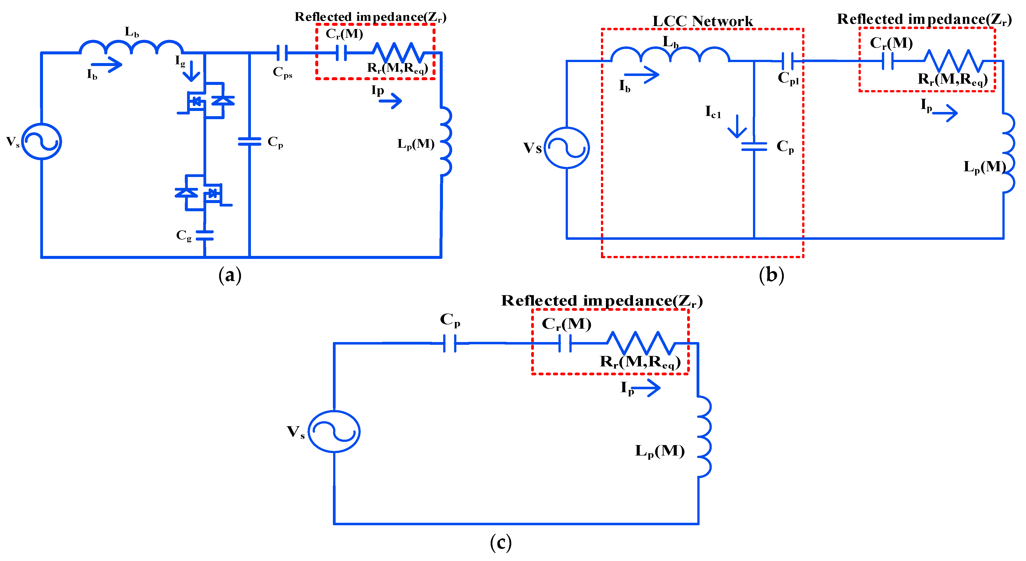
3.2. H-Bridge Inverter Configured Using LCL Resonance for High Gain

High DC–DC voltage gain is a particular goal of the high-gain LCL architecture, which lowers the level of input voltage needed. Figure 6 depicts the simplified circuit of the high-gain LCL-based WPT system [34]. The current can flow in both directions when a pair of back-to-back semiconductor switches are linked. The main parallel capacitor is a more reactive power-efficient compared to the usual LCL configuration, thanks to a modification [33]. The equivalent secondary capacitance can be written as:
C s e q = 1 C e q ω 2
Here, Cg and Cp together make up Ceq capacitance. The reflected capacitance in each of these topologies is expressed as
C r R e q , M = R e q 2 ω 2 C s p L s e q 1 2 + ω L s e q 2 ω 4 M 2 R e q 2 C s p ω 2 C s p L s e q 1 2 + L s e q
This equation clearly shows that the reciprocal inductance depends on the reflected capacitance. The mismatched distance between the coils affects the mutual inductance. Furthermore, reflected capacitance affects the resonance’s operating frequency. Consequently, reflected resistance [34] Rr is denoted by the following formula:
R r M , R e q =   ω 2 C s L s e ω 2 C s L s e 1 R e q ω M 2 R e q 2 ω 2 C s L s e 1 2 + ω L s e 2
In a WPT system, the voltage gain under misalignment is higher for the high-gain WPT system that uses an LCL-based design compared to the conventional SLC and LCL-based designs. This is even true at a loosely linked range. Therefore, this converter is suitable for a WPT system that has a significant misalignment. During the resonance period, the component that depends on R vanishes. This ultimately implies that this system’s resonance frequency will not be affected by variations in load during the resonance. The relationship between mutual inductance and primary current determines the open circuit voltage.
Consequently, the secondary current is likewise decreased for a loosely linked system. The magnitude of the primary current and operating frequency is significantly influenced by the secondary resonance. Based on how the secondary circuit elements are arranged, the reflected capacitance is determined.

3.3. H-Bridge Inverter Configured Using LCL Resonance

Figure 3 shows a standard H-bridge inverter, while Figure 6 illustrates the arrangement of energy storage components for the equivalent LCL resonance architecture, which allows the hybrid resonance to feed the input AC voltage. This is an LCL with LCC compensation. Primary equivalent inductance (Lpeq):
L p e q = L p 1 ω 2 C r 1 ω 2 C P L  
Primary series capacitor ( C P S ) :
C P S = L s e q ω o 2 L Δ P L s e q M 2
L s e q = 1 ω 2 C P P
Here, C r equals capacitance, M represents mutual inductance between the coils, and C P L is the principal series variable capacitor [35]. An equivalent primary inductance is created by modifying the circuit’s series capacitance and the primary inductor. The H-bridge inverter’s output current is constrained by the bridge inductor L b . The principal equivalent inductor L p e q and the capacitor C P S are in resonance. Adjusting the main compensation capacitances enables the LCL-based WPT system to handle a large load. Misalignment affects the reflected capacitance, but significant changes in misalignment have a limited impact on equivalent inductance. This results in a progressively reduced frequency change required to maintain resonance under misalignment.

3.4. H-Bridge Inverter Configured Using SLC Resonance

Figure 6 shows how the energy storing elements are arranged for the similar SLC resonance structure. According to this case, primary compensation capacitance (Cp) is:
C P = L s e q ω 0 2   L s e q L Δ P M 2
Because of primary equivalent inductance, change in inductance ( L Δ P ) is:
L Δ P = L P L p e q
Different arrangements of energy storage components can generate the second-order resonant frequency in WPT, such as SP, SS, PP, and PS [36,37,38]. The efficiency of the SLC design is high even under heavy load, but its light load efficiency is relatively low.

3.5. Direct Conversion of AC-to-AC Energy Topologies

This high-frequency inverter used in typical WPT applications transforms a DC source into a high-frequency inverted AC supply [27,39]. This technique for generating high-frequency AC from lower frequency AC was less power efficient, since there were more conversion processes involved.

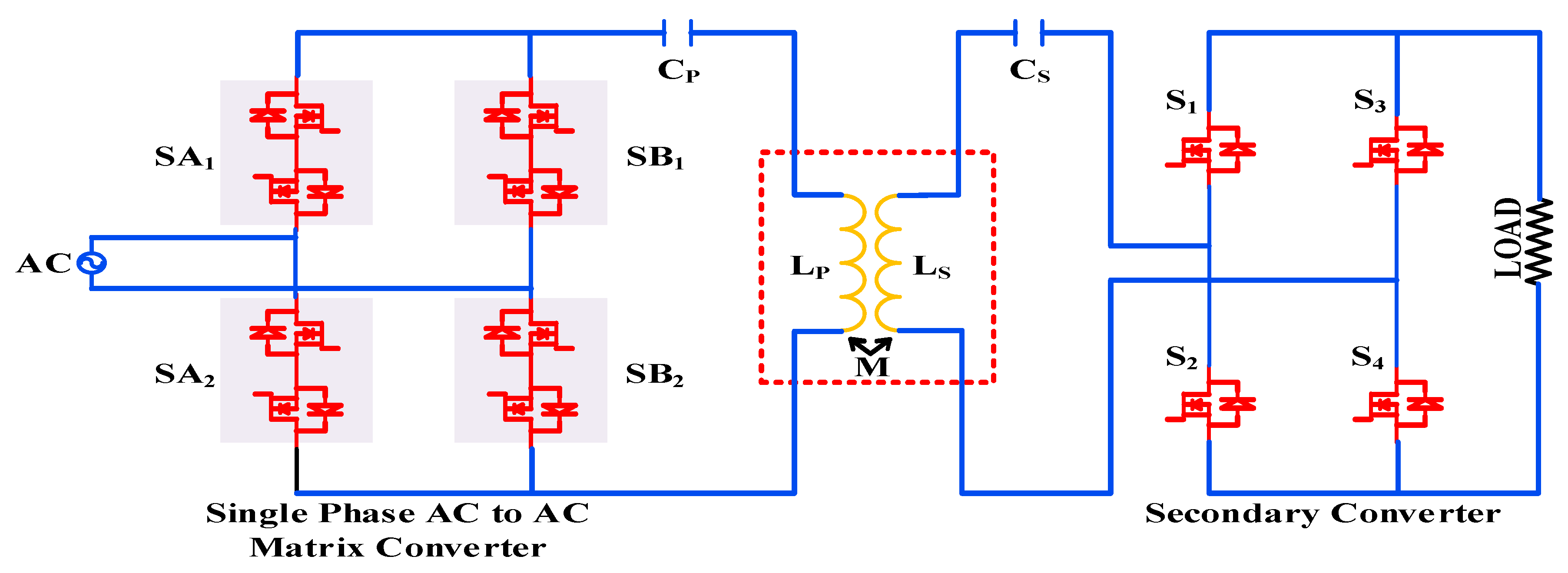
3.5.1. Converter Matrix Topology 1

Matrix converters were able to do this task satisfactorily in the given circumstances. Compared to older converters, the matrix converters made the bidirectional power transfer easier. This system displayed remarkable power density due to the energy storage components being lowered more than usual. This increased the system’s dependability. However, the operation is difficult since there are more bidirectional semiconductor switches, as shown in Figure 7 [27]. This method resulted in output voltage and current of subpar quality. Semiconductor switches required specific consideration in order to operate concurrently. To ensure increased efficiency, the switches are required to be soft-switched. The resonant current for fundamental harmonic ( I 1 m n ) is:
I 1 m n = V 1 m n R e q = ± m + n V a c 4 π R e q
Power transfer rate ( P t ) is:
P t = 1 2   R e q I 1 m n 2 = V a c 2 m + n 2 32 π 2 R e q
Here, Average power transfer rate ( P m ) is:
P m = V A C 2 m + n 2 32 π 2 R e q
Here, Req means reflected equivalent resistance for the primary side.

3.5.2. Direct AC-to-AC Converter Topology 2

The use of a direct AC–AC converter can address the key issues associated with matrix converters. This converter has the capability to convert less-frequency power into large-frequency alternating current [40]. One normal converter is shown in Figure 8, which operated by free oscillation to regulate the energy it injects. The design allows bidirectional energy transfer, and reflections from other circuit components are detected by the primary side. Resonance is caused by the circuit’s lumped inductor and series tuning capacitor. The voltage across switch is Vp. If Vp = Vac sinβ, then it is injection and, similarly, if Vp = 0, then it is oscillation.
The complete expression for track current ( i L ) is:
i L = V C 0 ω L   e t τ sin ω t + i L 0 ω 0 ω   e t τ   cos ω t + θ
Here i L 0   is inductor’s current similarly and V C 0 is initial voltage of capacitor, respectively. [ 2 L R e = τ ]. Resonance frequency: ω0 =   1 L C . These matrix converters’ greater switching density will result in a worsened THD and power factor. This converter needs much work before it can be used to charge electric vehicles. Testing for EMC compliance will be difficult now because of the converter. Therefore, the converter is a poor choice for the WPT system. The next part covers the Class-E-based WPT mechanism.

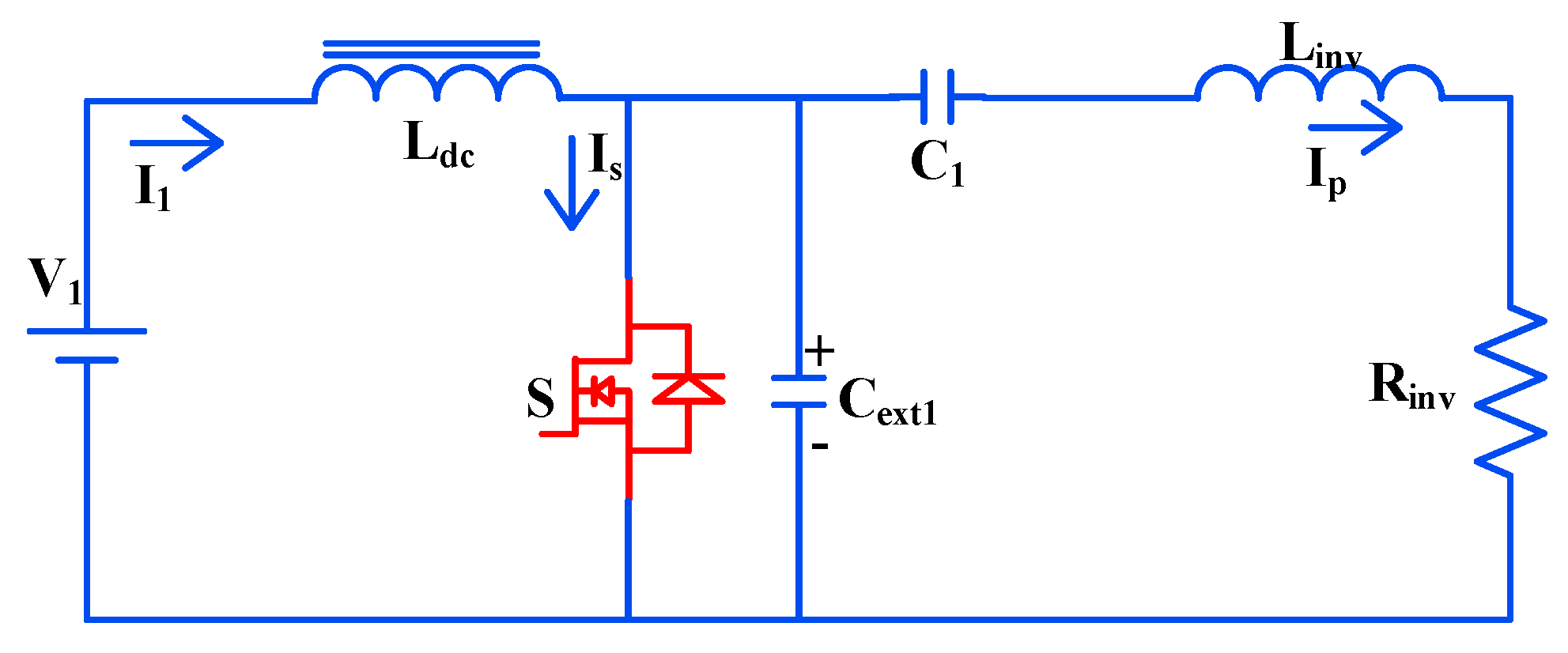
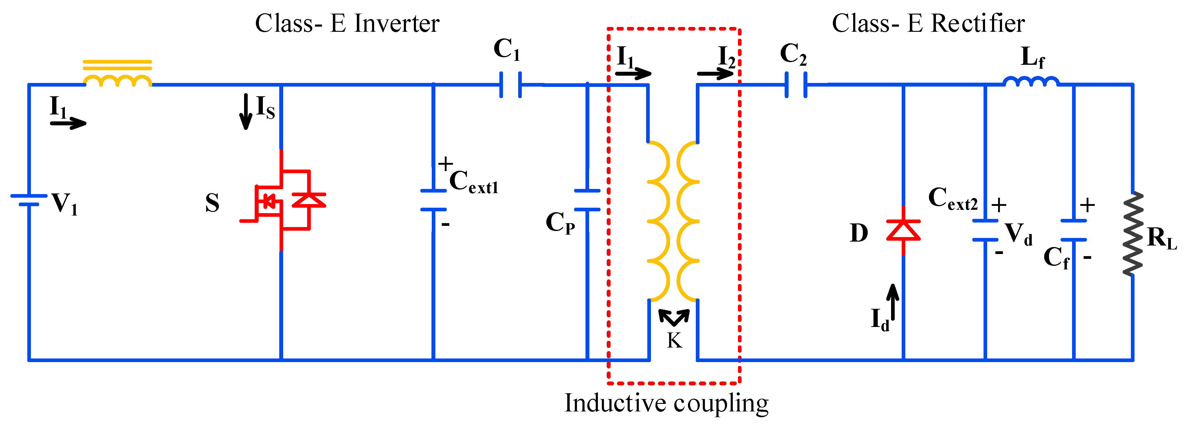
3.6. Class-E Inverter

Class-E inverters are commonly used for the low-power applications due to high switching stress. However, the high efficiency required to transmit power effectively is provided by the Class-E based architecture, with fewer semiconductor switches. Additionally, it will make the system more compact [41,42]. The traditional Class-E converters that are now on the market operate with a high frequency and high-quality factor. Because of this, the components of the circuit are reduced. This is yet another core part for producing the large alternating current required by the inductive coil. The magnetic coil and included resonance architecture simplify and condense the circuit. All secondary linearly calculated energy storage devices [43], together with their equivalent circuit, are referred to against the main wing for analysis, in order to determine effective impedance disclosed from source. The inverter runs in the MHz band for preservation of the quality factor of the receiver side [44,45]. Figure 9 depicts the impedance transformation capacitance C P and the resonance series capacitor C 1 . Here L i n and R i n are represented as
R i n = R e q + r L 1 C P 2 ω 2 ω L e q 1 ω C p 2 + R e q + r L 1 2
L i n = L e q 1 ω 2 C P L e q C P R e q + r L 1 2 C P 2 ω 2 ω L e q 1 ω C p 2 + R e q + r L 1 2
Here R i n and L i n are the equivalent inductance and resistance values for a simplified inverter when compared to other circuit components. A series resonance circuit is created by connecting capacitor C 1 in series with L i n and R i n . A good examination can yield the inverter’s switching pattern.

3.6.1. Class-E2 WPT System

A single switched device called a Class-E rectifier is used to diagnose greater frequency of switch with reduced voltage ripple. As a half-wave rectifier, a single diode is connected [46,47]. The Class-E2 WPT system is seen in Figure 10. Class-E inverters and rectifiers keep the system functioning. According to Figure 9, the Class-E inverter is made up a single coupled switch S.
Here input capacitance (Ci) is:
C i = 4 π C d ( 4 π 1 D d + 4 s i n 2 π D d 2 s i n 2 d s i n 4 π D d c o s 2 d )
Here, C D is MOSFET-’s parasitic shunt capacitance and C i means input capacitance [22,23]. Equivalently, rectifier’s input resistance ( R i ) is:
( R i ) = 2 R L s i n 2 d
As for the phase shift ( d   ):
d   = tan 1 1 cos 2 π D d 2 π 1 D d + sin 2 π D d
Here, d   is phase change between voltage and current and D d is diode on duty ratio circuit of Coupling. Equivalent resistance ( R e q ) is:
R e q = k 2 ω 2 L 1 L 2 r L 2 + R i ω L 2 1 ω C r 2 + r L 2 + R i 2
Equivalent inductance ( L e q ) is
L e q = L 1 1 k 2 + k 2 L 1 r L 2 + R i 2 L 2 C r + 1 ω C r 2 r L 2  
Here, L 1 , L 2 are the primary and secondary inductances and k the coupling factor. Like this, r L 2 equals the secondary pickup coil’s internal resistance [44,46]. C r is the reflected capacitance the Class-E inverter may be broken down into using R e q and L e q . Using Class-E based as well as derived circuit topologies in future solutions looks promising. However, a major improvement is required if the circuit architecture is to be employed for electric automobiles [22]. The next part, which examines the circuit from a different angle, addresses the drawbacks of these Class-E converters.

3.6.2. Compact High-Efficiency WPT System

This is another unique technology that operates differently than the standard [48]. The pulse position is employed for operating a higher-frequency inverter in this case. With a proper compensating capacitor combination, an unregulated rectifier is linked to the secondary pickup coil.
A low pass filter is also used to link the rectifier to the load [49]. By using S1 and S2 switches and D1 and D2 diodes, high-frequency alternating current is generated, as shown in Figure 11. The architecture incorporates the resonance circuit in such a way that energy storage and transmission occur via semiconductor components. Furthermore, compared to the LCL architecture, this converter can provide superior control over the resonance [47,48,50].

3.6.3. Equivalent Circuit of Class-E WPT

Figure 12 depicts the analogous circuit of the small, high-efficiency WPT system. The fundamental components of the WPT system are usually referred to as the analogous secondary circuit parts. The secondary circuit receives the energy used by the reflected branch. When switch S 1 is activated, diode D 1 , used as a forward-biased diode, charges inductor L C . Switches are switched on in tandem. After switch S 1 removes the gate pulse, the body diode’s conduction causes the current to flow via inductor L c . Switch S 2 and the matching body diode conduct if the inductor current discharges. As a result of this process, the inverter operates on pulse position as opposed to pulse span.
Primary current passing through inductive coil ( I p ):
I p = V d c ω C p 1 R r ω C p 1 J 1 ω 2 L s e q C p 1
Correspondingly, secondary track current [ i s t ]:
i s t = I s m sin ω t
Here:
= tan 1 ω L s e q   R e q   1 ω 2 L s e q C s p

3.7. Comparison of Topologies

Depending on the kind of load attached to it, every topology provides a different set of advantages. The prevalent topologies now in use are compared based on variations in efficiency and voltage gain. Additionally, several influencing factors on the resistance, SOC and SOH are all important for the state estimation of lithium batteries. If the charging current together with voltage fluctuates, the steady-state resistance of the battery will also change [48,51,52]. While the battery is being charged, the average current gradually decreases. If not, the initial charging period will have a high current. In turn, this results in high steady-state resistance. For the same reason, there is also a change in the reflected resistance from the load side. This section examines the influence of this variation based on research [53,54]. At the receiving end, the diode bridge is not linear. The diode bridge’s projected equivalent linear resistance is derived by dividing the fundamental RMS voltage by the fundamental RMS current.
Now equivalent resistance (Req) is:
R e q = π 2 R L 8
Here, Req stands for state resistance and RL represents load resistance. The coil changes affect the current due to load fluctuations. In the event of a failure or short circuit, a significant amount of electricity may be drawn from the source. This can be anticipated, and the converter can be designed to accommodate these conditions [55]. A compact, high-efficiency design uses fewer semiconductor components compared to other topologies, while a high-gain LCL architecture employs more semiconductor components. These two topologies have distinct applications and display different characteristics under varying load conditions. The standard LCL architecture is well regarded for its reliable performance in this field. Similarly, the high-gain LCL architecture achieves exceptionally high voltage gain with lower coupling coefficients. Its high-efficiency capability ranges from 85% to 90%, depending on the load, whereas LCL efficiency ranges from 73% to 86%. Class-E based devices operate at frequencies in the MHz range and can comply with SAE and QI standards. The high-gain LCL can be used in both LCL and high-gain modes, achieving similar properties to LCL while offering greater control flexibility compared to other topologies. Advanced near-field wireless energy transfer technology, such as the powerful electromagnetic wireless power transfer (WPT), is the most sophisticated. Despite certain limitations, the complexity of the WPT system has enabled testing and implementation of various proposals for variable charging of top devices through electromagnetic fields.

4. High-Order Compensation Topology

Inductive resonant couplings are used in WPT, which have recently undergone extensive study, particularly for wireless EV charging systems. Wireless charging provides a contact-free energy transfer method, avoiding the need for bulky connectors or wires, making it more practical and versatile. This allows for charging in diverse situations and locations [56,57]. Dynamic charging solutions, such as in-motion charging, are a significant research focus to address the range anxiety associated with low battery capacity. While significant advancements have been made in stationary wireless power technology, there is growing interest in quasi-dynamic charging solutions. The literature on WPTs utilizing resonance principles predominantly focuses on the fixed frequency technique [58,59,60]. Designing, analyzing, and operating WPTs requires a comprehensive approach, considering factors that enhance efficiency and power output, various potential resonant frequencies, Zero Phase Angle (ZPA) or Unity Power Factor (UPF) efficiency, Constant Current (CC) and Constant Voltage (CV) modes, fixed or variable frequency schemes, and hybrid CC/CV profiles for Li-ion batteries, which are the most common type for EVs.

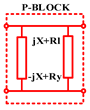
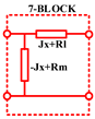
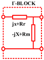
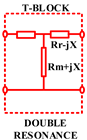
4.1. Fundamental Resonance Blocks for Power Transfer Systems

LC (inductor–capacitor) resonant circuits are essential components of efficient WPT to EV. In designing WPT, both single and double resonant blocks based on LC resonance are commonly used [60]. Two main types of resonance blocks influence the design of the primary and secondary coils: the S-block and the T-block. The T-block serves as a double resonance block and is especially beneficial for analyzing dynamic systems.

4.1.1. Single Resonance System for WPT

Based on LC resonant circuits, basic single-resonance blocks are available in series (S) and parallel [(P), (Γ), and (7)] configurations to connect resonance components, as shown in Figure 13. Each block in the WPTs represents an energy transfer system that uses power sources in either Constant Current (CC) or Constant Voltage (CV) modes to transfer energy to load Zo [60,61,62]. Generally, the source is modeled as an ideal CV or CC source with internal impedance ZVI or ZCI, respectively, using Thevenin’s theorem or Norton’s theorem. The parasitic resistance Rs of the components in the transmitting blocks using resonant LC circuits is equal to the equivalent resistance Ro of the load Zo. To determine the effects of resonance on efficiency, input impedance, and output power, a thorough analysis of the S-block transfer system with a non-ideal CV source is conducted.
Resonance on efficiency:
η S C V = R 0 / R 0 + R v i + R s   |   R s = R r + R l
When using a CV source, the resonant condition on Xs does not impact on efficiency of energy transfer [63]. On the other hand, the efficiency decreases when the parasitic resistance Rs is increased.
η S C C = R 0 R s + R 0 + Z 0 + Z s Z c i 2 R c i
Resonance condition with Z0 minimizes energy loss in CC source, which improves efficiency. When the load is purely resistive, resonant condition for highest efficiency is Xs = 0.
Output power:
P S C V = V i 2 R 0 Z 0 + Z s + Z v i 2   |   Z s = Z l + Z r
The S-block’s resonance condition with Z0 along with source Z0 (Xs + Xvi + X0 = 0) results in maximum power output for (CV) source. When the source is the ideal CV source, the resonance condition simplifies to Xs + X0 = 0, which corresponds to UPF (unity power factor) conditions for that circuit from the CV source. ZPA/UPF gives peak effectiveness and the highest possible power output to the load. Table 2 shows the single and double-resonance blocks for wireless power transfer systems.
P S C C = I i 2 R 0 Z 0 / Z c i + Z s / Z c i + 1 2  
Resonance condition enhances the power output, Xs + X0 = 0, and Xci is high in case of Constant Current. Input impedance is
Z S i n = Z S + Z 0
Impedance Zin of the circuit satisfies ZPA/UPF state, where Zin = Rs + R0 and Xin = Xs + X0, equals zero. By employing absolute source in S-block, this identical synchronization situation is present for attaining ZPA/UPF with peak effectiveness and the highest possible power output to the load.

4.1.2. Double Resonance System for WPT

In dynamic wireless charging, double resonance block (T-block) [64] has an important role. Figure 14, A generalized block diagram of inductive coupling systems. T block is made by combining parallel single resonance block (7) and (Γ). Therefore, it has more advantages than other resonance blocks. Efficiency of T-block is given as
η T C V = R 0 R r o + R r o 2 + X r o 2 R m Z m 2 + R m r o 2 + X m r o 2 R l v i Z m 2
where Zro = Zr + Z0; Z m 2 = R m 2 + X m 2 ; Zmro = Zm + Zr+ Z0; and Rlvi = Rl + Rvi. Subscript Zl, Zr, and Zm represents similar characteristic impedance of T-block’s left, right, and middle components, respectively. Maximum efficiency:
X r 0 = a r g   m a x η T C V = R l v i X m R l v i + R m
It should be emphasized that the resonance situation is beneficial in minimizing parasite and inner source resistance losses (Rlvi = Rl + Rvi), which is why T-blocks are used. The resonance condition in this case depends heavily on Rm. This is influenced mostly by the ESR of parallel capacitors [65,66,67] in compensating tanks in linked coils. When Rm deviates from null, it becomes an issue to consider in mistuned settings in WHPT systems. Zm’s value has a significant impact on efficiency. The value of Xm has notable effect on loss in Rlvi, which is important to observe in weak-coupling systems. When Rm = 0, the resonance condition Xro = −Xm, as illustrated in Table 2 [64,68,69]. The single requirement for a-block is set for optimal efficiency. It is vital to remember that, in the case of CV sources, the resonant block determines efficiency.
Figure 15 shows the four typical methods for compensating for and/or improving the efficiency of WPT systems. Compensation can be achieved using four basic forms based on self-inductance: S/LC compensation, LCL compensation, LCCL compensation, and intermediate coil addition compensation. Self-inductance is converted into resonant S- or T-blocks using capacitors, inductors, and capacitors in LC-/LCC circuits, or intermediary coils connected in series with capacitors. The S-block aids in power transfer and maintains Unity Power Factor (UPF) or Zero Phase Angle (ZPA) but does not enhance efficiency [68]. Due to its simple construction and absence of inactive components, the S–S topology has fewer parasitic resistances. However, this topology’s efficiency is significantly reduced under weak coupling conditions (small Am) with non-optimal power sources (presence of Rvi). T-blocks with large inductors (Lf) are not ideal as they exhibit high parasitic resistance and potential core loss. To reduce the Lf value and lower inductor costs, the LCC topology is used instead of the LC topology, incorporating an additional capacitor in series with the original coils [70,71].

4.1.3. T-Block Model Appropriate for DWPT

In EV charging systems, the main coupling resonators in each inductive wireless power transfer (WPT) system are modeled using a T-block, as shown in Figure 13. However, designing the inductive coupling coils is challenging due to variations in mutual inductance (Lm) or coupling coefficient (k) [64,69,72,73,74]. A T-model, built on a loosely coupled transformer with components for mutual and leakage inductance, is often used to address this issue. Strategies can also be employed to account for self-inductance. The ideal T-block for main couplers in inductive WPT can be connected to other built-in elements to achieve resonance at a specific frequency [73,75]. This double-resonance condition can be met at any frequency and with any value of mutual inductance (Lm), simplifying the design process. The T-block can be linked to additional blocks, such as the S–S topology. Compensation techniques can maintain resonance conditions on both the primary and secondary sides by accounting for self-inductances (LTx and LRx). However, when there is no load or no coupling between coils, the T-model used to transform the initial CV source into a CC source may encounter problems [75]. To address this, T-model-based solutions can be used to mitigate the effects of Rvi and small Xm on efficiency. The CC/CV characteristics under loads with large coupling coefficients can also be adjusted by adding additional T-blocks.

4.1.4. Highly Flexible Compensation Topologies

In a WPT system with loosely coupled primary and secondary coils, there is a significant amount of reactive power [75]. Compensation topologies are necessary to offset this reactive power, essential for achieving high-power density, efficiency, and flexible output. However, misalignment between primary and secondary coils can introduce variations in mutual inductance, resulting in fluctuations in input impedance, reduced stability of output power, and decreased overall system efficiency.

4.2. High-Order Topologies

Higher-order compensation topologies, incorporating additional inductor (L) and capacitor (C) components, are utilized in WPT to improve misalignment tolerance. While the inclusion of extra components can reduce system efficiency, it enables the attainment of desired characteristics, such as load-independent input impedance, stable output, high-power density, and enhanced misalignment tolerance. Various higher topologies have been developed, including S/SP [76,77], S-LC [77,78], S-CLC [78,79], CLC-S [80,81], LCL-S [82,83], LCC-S [84,85,86], LCC-P [87,88], LCL-LCL [89,90,91], and LCC-LCC [63,92,93], alongside parameter design strategies aimed at mitigating coil misalignment and accommodating load variations. Table 3 shows the various hybrid compensation topologies.
Adding more compensation components to a WPT system provides greater design flexibility [94,95,96]. The CLC, LCL, and LCC topologies allow for adjustment of the constant output amplitude by varying the values of Lf and Lf1 [97,98,99]. However, the LCL topology’s lack of design flexibility is due to the necessity for equal inductance values between the main coil and compensation inductance [100,101,102]. CLC-S compensation allows for a smaller compensation inductor (Lp) than LCC-S topology, leading to reduced system volume and power losses [103,104]. However, operating angular frequency of S/SP and LCC-P compensation is a function of Mps, making system design more difficult and complex [105,106,107].

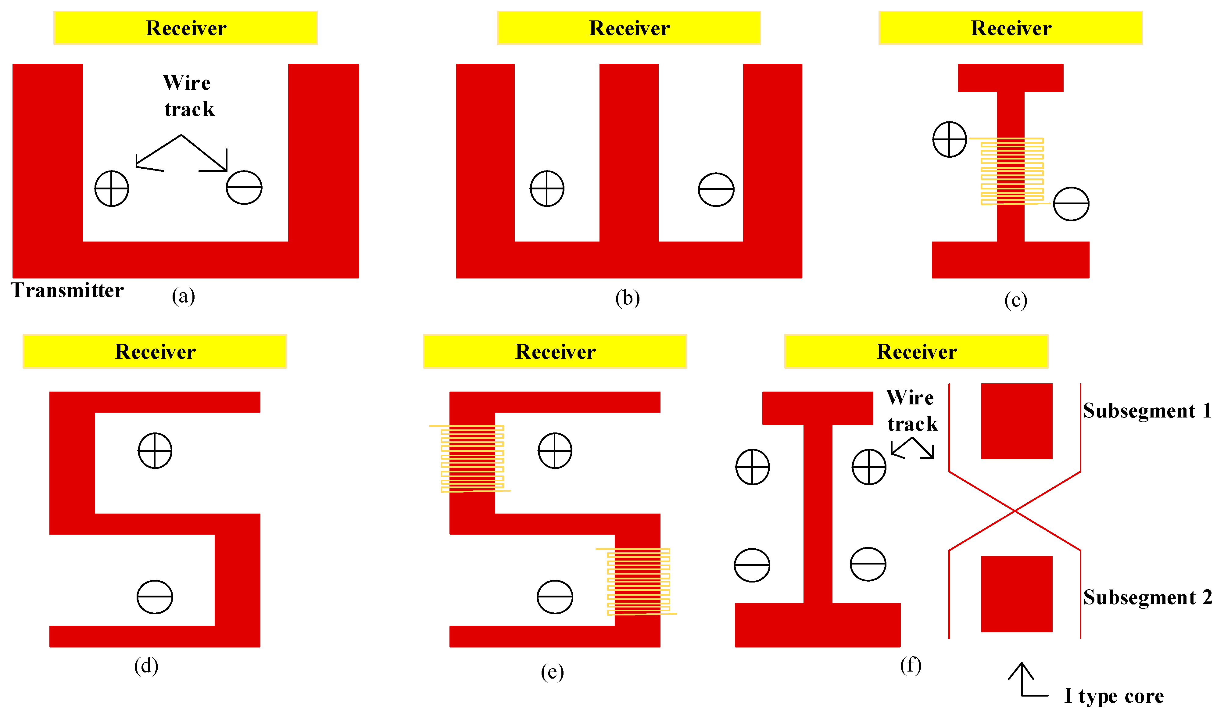
5. Magnetic Coupled Transmitter Pad Architecture

Electric vehicles can now be charged while in motion thanks to dynamic magnetic power transfer systems, obviating the need to halt and wait for charging to finish [108,109,110,111]. This seeks to enhance long-distance motorway travel by significantly extending the range of electric vehicles with a small onboard battery [112]. Storing a transmitter coil and securing the receiving coil to the vehicle’s undercarriage allows for active charging. However, there are several obstacles to the widespread adoption of dynamic charging, including the high installation costs, the need for a dedicated charging lane [113,114], and the requirement for precise alignment to avoid power losses. DIPT devices have two transmission options: a segmented coil array or a lengthy single coil track.

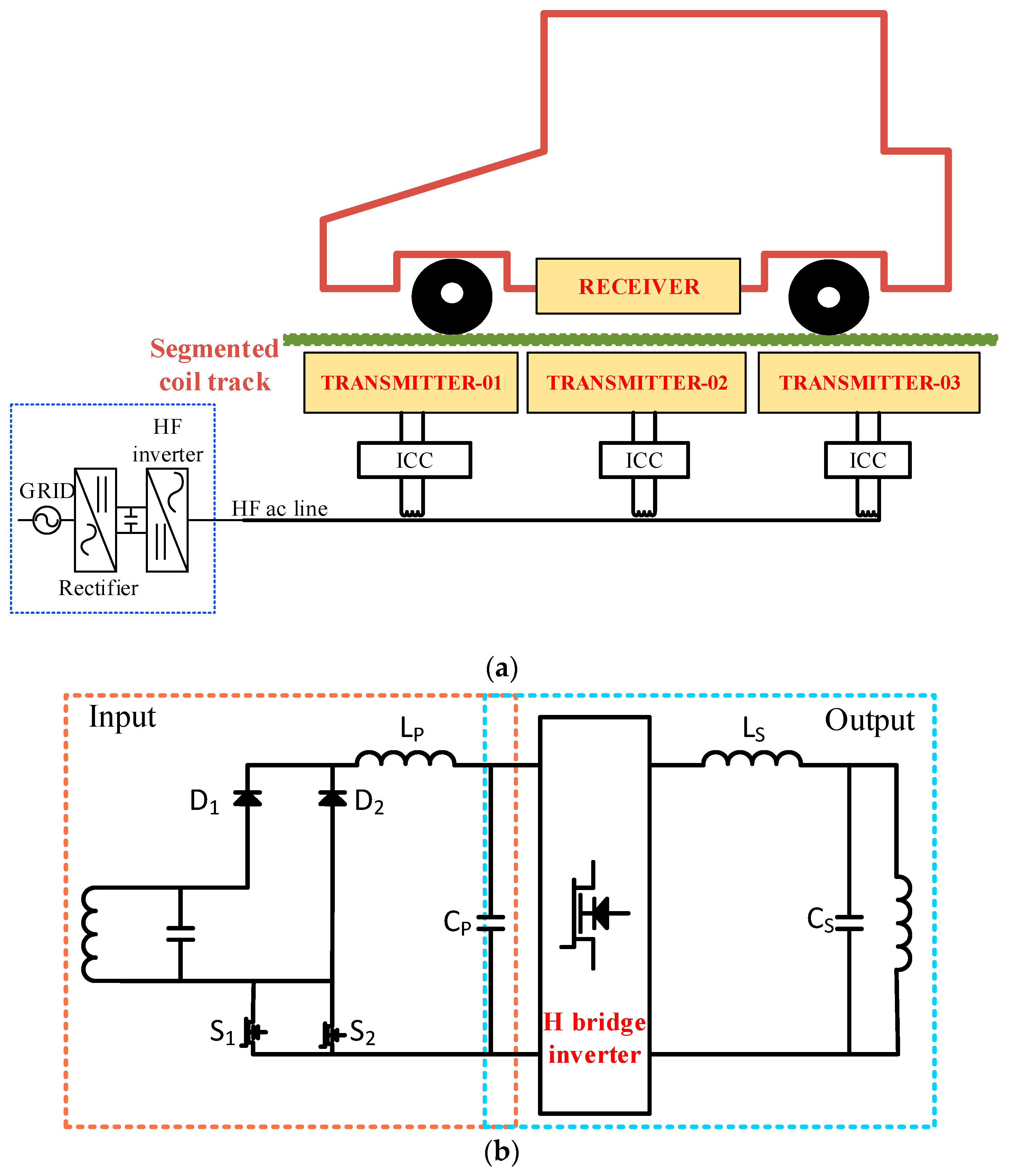
5.1. Track with a Single Long Coil

The DIPT system includes a transmitter with a long coil track that is lengthier than a receiver pad, allowing charge of many vehicles at the same time. It comprises a resonant network transmitter station, an HF inverter, and a rectifier-like device (Figure 16). This system is straightforward to configure and design, making it simple to operate [115,116]. The fixed mutual coupling within track and receiver coil provides various advantages. In South Korea, the OLEV system was demonstrated in shuttle services.
Although the long single coil track for dynamic charging has some advantages, such as easy operation and constant mutual inductance [117], it also has some disadvantages, such as high losses and maintenance costs. Moreover, coupling coefficient is decreased when the car does not travel along the transmitter track, resulting in low transmission efficiency. To address these issues, the transmitter track has been divided into various shapes, including type-U [118] type-E [119], type-I [120,121,122], and type-S [123,124,125,126], based on the magnetic core’s form. The effectiveness of these types is compared and summarized in Figure 17 and Table 4.
Dynamic inductive power transfer (DIPT) systems need a long transmitter track that is only activated when electric vehicles (EVs) travel over it and deactivated when they do not [127,128,129]. To achieve this, the extended transmitter track is segmented into several sub-tracks. Each sub-track can be activated by supplying a high-frequency current through an inverter-powered switch box [130]. One type of segmented track is the centralized switching track, which includes multiple sub-tracks, a set of connectors, and a central switching box, as illustrated in Figure 18 [131,132]. The switch box connects one of several pairs of supply lines to the inverter at any given time, necessitating numerous power cable bundles, which leads to high installation and maintenance costs. Another type of long partitioned track is the scattered switching track, which features multiple switch boxes placed between sub-tracks and connected to a pair of standard power supply cables.
This design is more cost-effective than the centralized switching track because it requires the least cable length and fewer power cable bundles [133,134]. Additionally, a single inverter can operate multiple sub-tracks, further reducing costs. Another advancement is the cross-segmented track, or X-track (Figure 8). This design includes auto-compensation switch boxes that redirect electricity from one pair of power cables to trigger leads from two pairs of power cables [135]. The X-track employs twisted power lines, a core, and copper nets to generate compliant electromagnetic fields that adhere to ICNIRP standards.

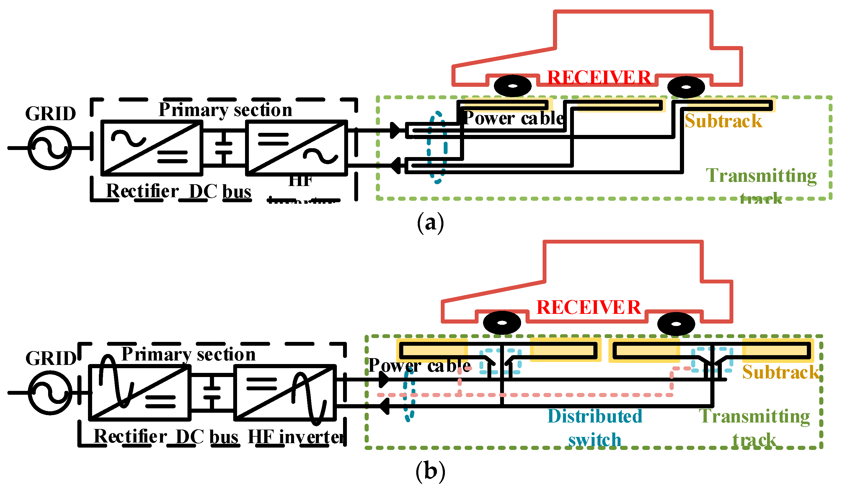
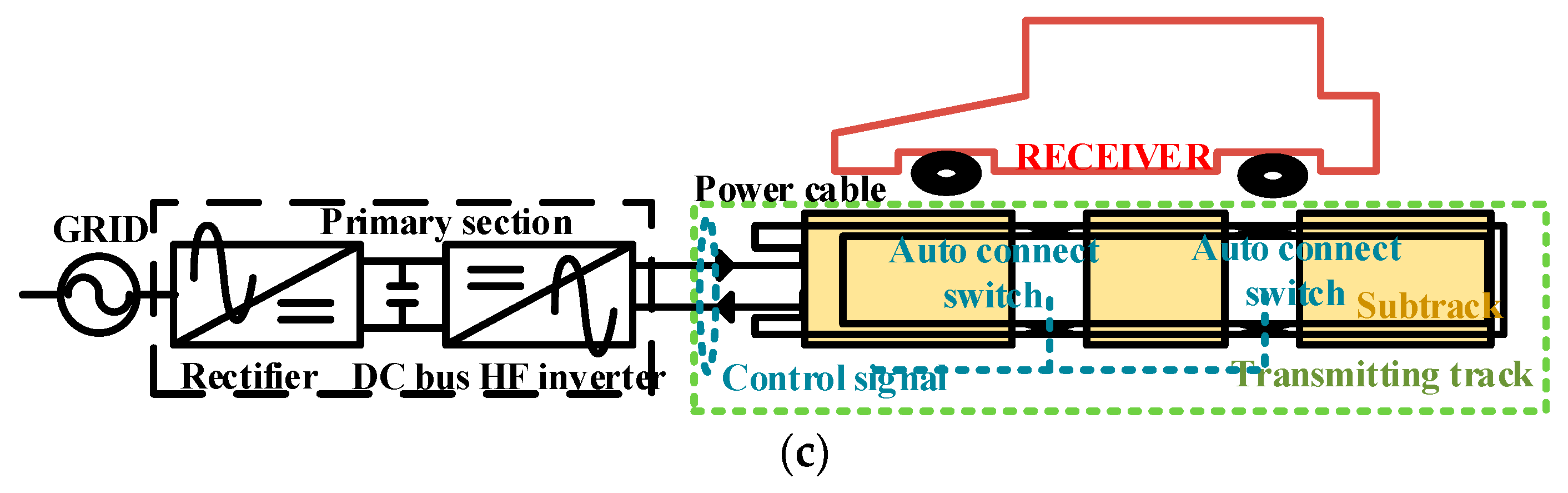
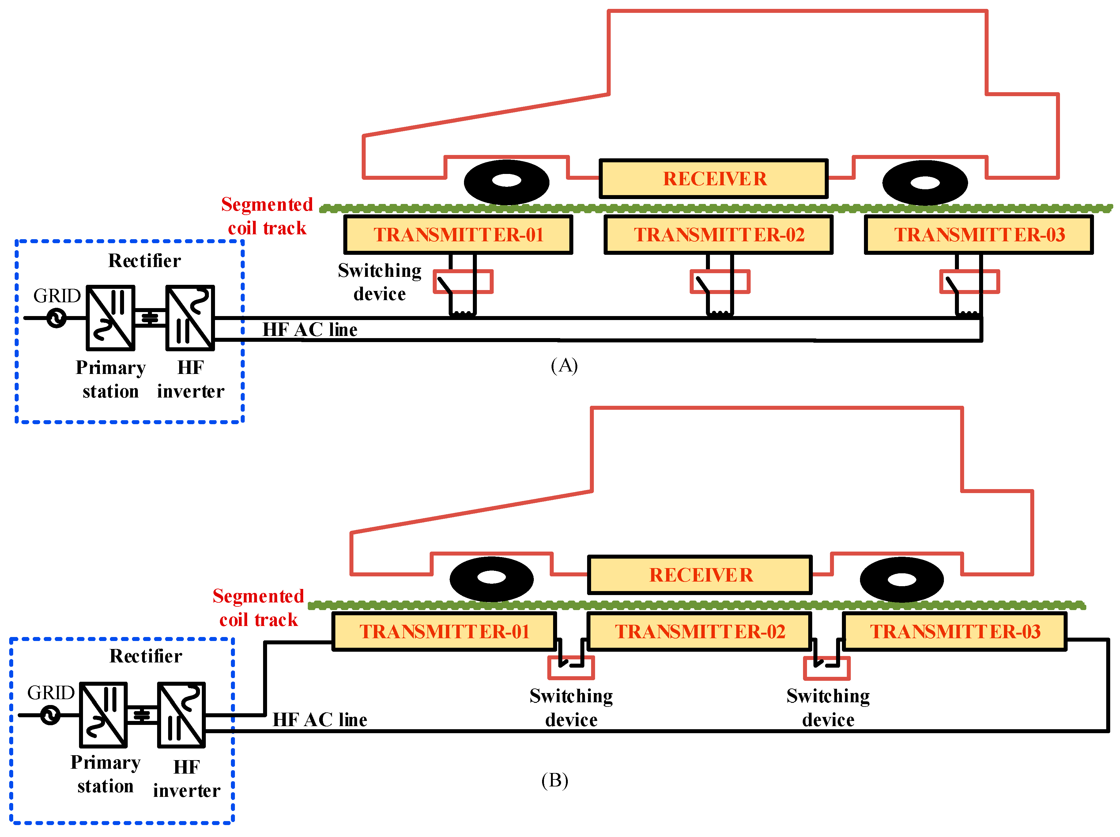
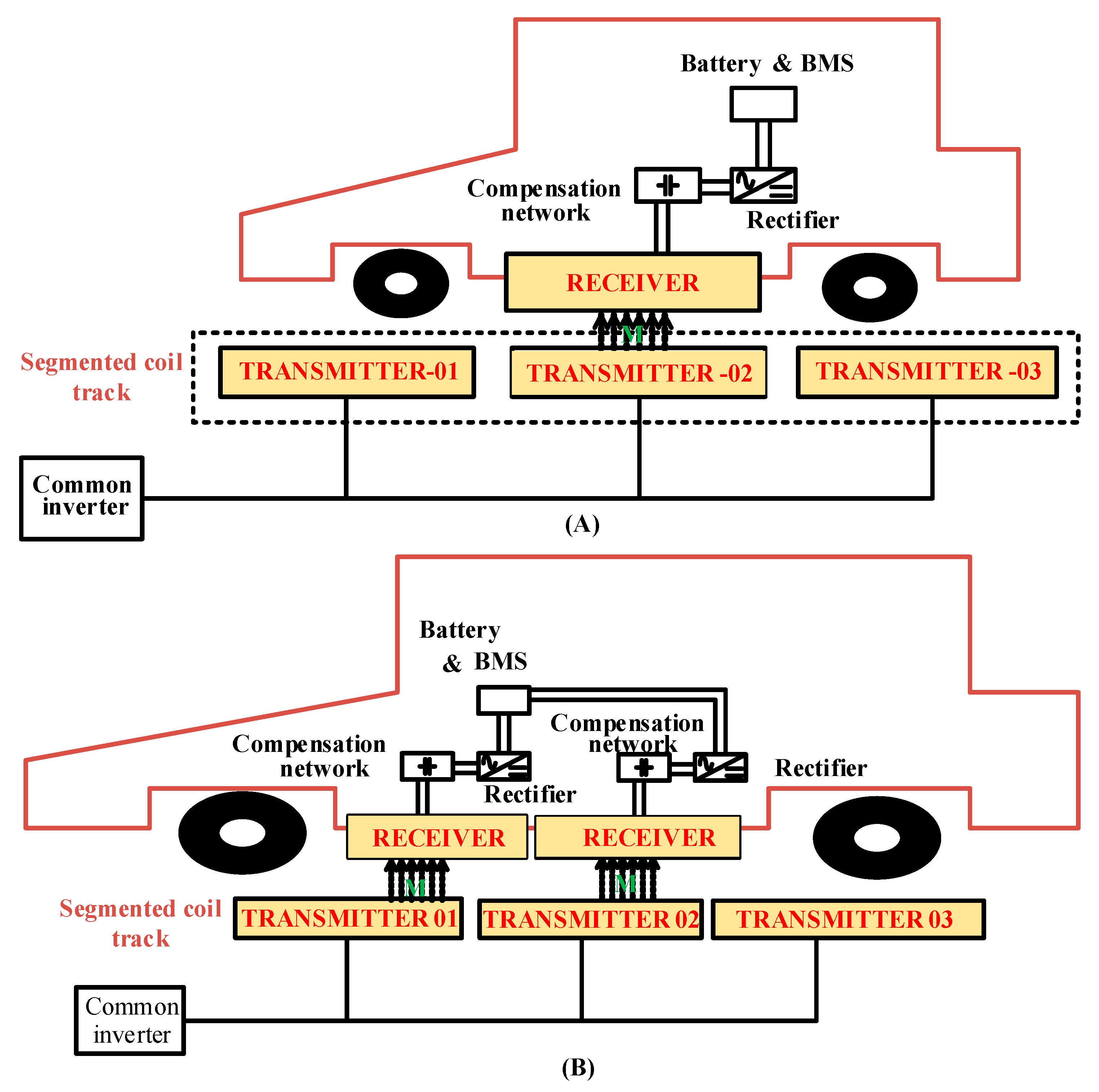
5.2. Segmented Coil Array

This coil matrix technology uses multiple coils, connected either in series or parallel and buried underground, to form the charging track, as illustrated in Figure 19. Each segment of the transmitter coil is similar in size to the receiver coil and includes its own compensating circuit, similar to the RIPT system [136]. Although this technology requires numerous compensating elements, inverters, and transmission coils, which increases material costs, costs can be reduced by designing the system with a series of coils sharing the same electronic power converter. A challenge with the coil array is the spacing between the transmitter coils due to their self-coupling. When the receiver coil is positioned between two transmitter coils, it results in a power potential of zero [137,138,139,140,141]. The resonant circuit design needs many coils to cover the same distance, even when the transmitter coils are placed close together to minimize power pulsation [142,143]. When the distance between the transmitter coils is approximately 31% of the transmitter length, the energy pulsation remains within 48% of the maximal power [144,145]. There are various alternative designs for the segmented coil array, each with its advantages and disadvantages. Using multiple coils is more demanding in terms of setup and operation but can be technically resolved. A long single coil is easier to install and use but emits a harmful magnetic field that reduces system efficiency. In a dynamic charging device with ground-based segmentation coils, there are two primary feeding techniques: the HF inverter and an independent compensating circuit [146,147]. The HF inverter allows the system to activate and deactivate based on the car’s alignment with the segmented coil, enabling the use of low-power inverters. Although straightforward to construct and operate, the compensating network enhances performance and reliability but requires numerous inverters and sensors.
There are two main configurations for feeding segmented coils using a high-frequency (HF) inverter (Figure 19) [148]. The first configuration involves each segmented coil having its own compensating circuit and switching device. The switching device activates and deactivates the system as the EV enters and leaves the charging lane. Although this setup utilizes a single inverter [149], the overall cost is higher due to the need for numerous charging segments.
In the second configuration, a single HF inverter feeds multiple segmented coils. This design mitigates safety concerns by using high frequency, allowing individual transmitter segments to extend from the transmitter power facility. However, it requires numerous switching and sensing devices, which increases the overall cost. A detection mechanism was developed to determine the EV’s position, charging the coil towards the receiver using a high-frequency current. The position of the reception coil can be identified by detecting the output current at the appropriate frequency. Alternatively, the phase angle between voltage and current is monitored to reverse without a location-detecting sensor [150]. To address the complexity and cost of these configurations, a new arrangement called reflexive segmentation was developed (Figure 20). This system uses a shared high-frequency inverter and non-resonant capacitors to compensate for the transmitter self-inductance. The current flowing through uncoupled transmit coils is low, producing a weak field. When the transmitting and receiving coils are coupled, the transmitter coil reaches resonance at the operating frequency due to the reflected impedance of the receiver. This enhances the transmitter’s EMF output, increasing the transmitted voltage.
In a DIPT system utilizing a segmented transmitter track, a bidirectional AC switch manages the charging of individual segments. Additionally, switching boxes can alter the current’s direction when it navigates a turn. Although only a few connections are needed, all charging segments are connected in series, requiring the complete current capacity certification for all switching boxes. The dynamic charging systems mentioned above face several challenges that hinder their practical application [66,151]:
  • Except for one, these systems lack isolation devices between the power supply and charging parts, increasing the risk of system failure if one section fails.
  • The presence of electrical circuits on highways is problematic due to vibrations and pressures from vehicles driving over them. The system must operate even if one or more transmitter parts fail, as component replacement and maintenance are costly and impractical.
  • The absence of communication protocols between EVs and charging infrastructure can lead to traffic congestion from multiple vehicles charging simultaneously and increased strain on the electrical network during peak hours. Power loss can also occur when additional equipment, such as entertainment systems or cabin heating/cooling, is used.
  • Most dynamic charging systems operate at 20 kHz, which is below the 85 kHz required by SAE J2954 regulations [152]. Meeting this standard requires a power supply capable of hundreds of kVA, which is challenging. Finding semiconductor switches that can efficiently function at this power level and frequency is particularly difficult, as IGBTs can handle high-power ratings only at low frequencies, while the latest MOSFET devices can handle higher frequencies but at lower power ratings.
A proposed solution for feeding the DIPT system is a double-coupled system involving an underground high-frequency power line and an intermediate coupler circuit (ICC) at the designated section [153,154]. By connecting the transmitted power twice—first between energy sources and the ICC, and second with the transmitter segments—this technology reduces transmission track losses. Figure 21 shows the additional supply solutions for DIPT system segmented transmitters that allow control of individual charging segments.
By operating at a low frequency while the transmitter part runs at a high frequency, this system mitigates the impact of dynamic recharging on the electrical system during peak hours. However, the use of a centralized power supply unit presents challenges, such as high costs for power electronics and limited stability. To achieve optimal conditions for EV operation, researchers have investigated using a split coil array as a transmitter. They suggest that factors like vehicle speed, energy consumption per kilometer, power loss, and charging efficiency should determine the length of the transmission coil.
Figure 22 shows the schematics of a doubled coupled system and intermediate coupler circuit (ICC). The study utilized various techniques to enhance power transmission efficiency and stability in dynamic charging systems. These techniques included employing a lengthy transmitter pad and an oblong receiver coil with LCC–S compensation [155,156,157]. Researchers investigated the optimal size and horizontal separation between transmitter pads to optimize system properties [158]. To further improve power transmission efficiency, transmission distance, and tolerance for linear misalignments, a double-spiral repeater was utilized [159]. Additionally, a coil combination was implemented in the track, and a double-coupled system was used for the segmented transmitter dynamic charging system to increase the number of active transmitters and reduce output voltage volatility. Six parallel coils were placed side by side to minimize power fluctuations [160]. Three methods were applied to reduce magnetic field loss on the I-Type core: ISEC, linkage-free EMF cancellation, and 3 dB dominant EMF cancellation. These approaches helped lower the leaking EMFs to levels within the permitted safety limits. The research also introduced an improved LCC circuit designed to deliver consistent and highly efficient output power under varying mutual induction conditions. In summary, the study employed a variety of techniques, including coil combinations, parallel coils, and LCC-S compensation topology, to improve power transmission efficiency and stability for dynamic charging [161]. Additionally, it used different methods to mitigate the magnetic field’s impact on the I-Type core and presented an enhanced LCC circuit for stable output power.

5.3. Structure of the DIPT Receiver Pad

Recipient side coils used for dynamic charging are similar to those used in static charging. The number of receiver pads needed varies based on the vehicle’s size and weight. Small, lightweight EVs might only need one pad, whereas medium and heavy EVs may require multiple pads [162]. Using multiple-receiver pads allows the system to support a broader range of vehicle types. To ensure optimal transmission efficiency, a dedicated compensation network is used to compensate each receiver pad individually. Figure 23 shows the schematic of receiver pad in DIPT system
An electromagnetic integrated topology was developed to address the issue of output voltage and power volatility caused by transmitter switching during EV driving. An experimental platform was created to investigate a one-transmitter multiple-receiver system, achieving an efficiency of over 80% under optimal conditions [163]. The authors analyzed the impact of cross-coupling on system efficiency and found that appropriate load reactance can improve efficiency while maintaining other essential system features [164,165,166,167]. Additionally, the authors investigated the use of a Z-source grid coupled to a three-coil MTSR system with S–S–S compensation to achieve Constant Voltage and zero-phase angle features without requiring switch dead time, enhancing the converter’s reliability. The MTSR system can also be used for EV dynamic charging and communication. A flexible moving STMR system with a compensation topology was designed to allow for simultaneous charging of multiple devices, such as 1–3 cellphones. By connecting a transmitter as a series-compensated, multi-level converter, the STMR system can be applied in various contexts, such as Maglev trains. The LCL–T was equipped with an MTMR device [161] and a compensation architecture to extend the magnetic transmission distance and achieve optimal efficiency at optimal power. These systems offer advantages like higher voltage, a more reliable power source, and improved signal quality, but they also increase in size and cost with the charging system.

6. Magnetic Materials of Wireless Power Transfer Systems

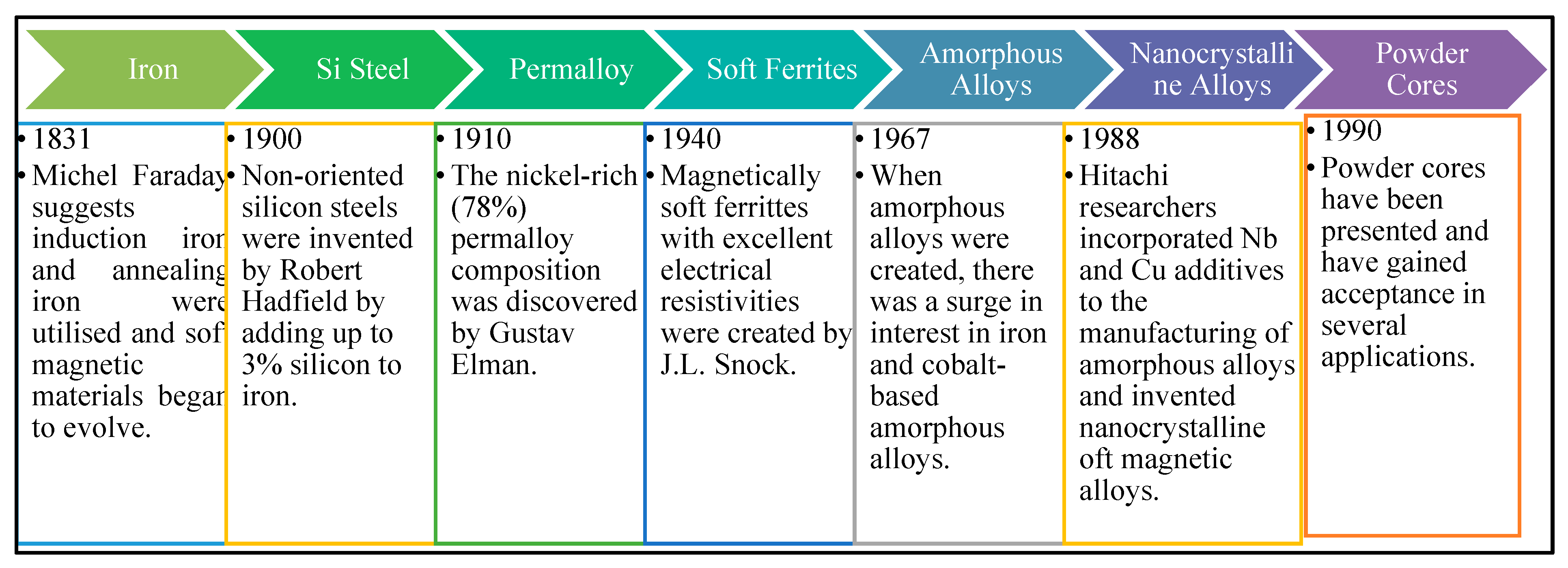
6.1. Brief History of Soft Magnetic Materials

Michael Faraday developed the law of induction in 1831 and, initially, iron was used as the magnetic core due to its high permeability, low coercivity, and maximum saturation magnetization. Soft magnetic ferrites, developed in the late 1940s [168,169], are now widely used in electromagnetic induction and high-frequency equipment, with manganese zinc ferrite being the most common in wireless power transfer systems. However, the energy density of components using ferrite cores is limited by the minimal value of saturation flux density. Amorphous soft magnetic alloys were first produced in 1967 and, by the mid-1970s [170,171], Fe- and Co-based amorphous alloys became popular due to their high saturation magnetic density and minimal power loss. Recently, various metals with low power loss and comparable saturation flux density have been developed, potentially reducing the lifetime cost of power electronics and motors. Granular core or soft magnetic composites (SMCs) were introduced in the 1990s [172,173]. These cores are created by mixing magnetic particles, typically iron or alloys, with insulating materials and then solidifying them under high pressure [174,175,176]. This manufacturing process allows for the production of complex magnetic core shapes, significantly reducing production costs. SMCs are ideal for use in electrical machines due to their isotropy, low cost, and ability to create complex shapes. They are also advantageous in high-frequency inductor design, as adjustments in powder size, insulating material [177,178,179], and pressure during production can minimize air gap losses and streamline inductor construction. Figure 24 shows the research progress and a brief history of soft magnetic materials.

6.2. Comparison of the Typical WPT Materials

Soft magnetic materials most commonly used in wireless power transfer (WPT) for electric vehicles (EVs) include amorphous and nanocrystalline alloys. Fe-based amorphous [172,173] and nanocrystalline alloys possess higher saturation flux densities compared to other materials, reducing their sensitivity to temperature fluctuations and enhancing their adaptability to various operating environments. Nanocrystalline alloys combine the transparency of Co-based amorphous alloys with the strong magnetic moment of Fe-based amorphous alloys [170], thereby increasing tolerance and reducing losses. Soft magnetic ferrites [170,171] have high resistance but are suitable for high-frequency and medium-frequency operations. The nanocrystalline alloy FeCuNbSiB and the amorphous Fe-based alloy FeSiB exhibit excellent magnetic characteristics and are well-suited for medium- and high-frequency systems due to their low resistivity. With the increasing demand for wireless fast charging, coils generate stronger alternating magnetic fields, leading to core saturation, decreased magnetic permeability, and reduced magnetic coupling efficiency. High-power WPT applications can cause magnetic saturation in ferrite cores. One practical solution is to increase the number of magnetic cores [175,176], but this also increases the system’s weight and size. Ferrite cores are also not ideal for onboard receiver applications in EVs due to their brittle and weak structure, which can lead to changes in system parameters and reduced efficiency. Table 5 shows the comparison of the characteristics between different amorphous. Also, Table 6 give the comparison of the EV–WPT system’s properties utilizing PC-95 Mn-Zn ferrite core.

7. Safety and Health Concerns

When designing WPTs, it is crucial to consider their impact on human health and their interaction with other devices. Several significant factors should be taken into account [179]:
  • Electromagnetic Interference (EMI): WPT technology should be designed to minimize EMI emissions, which can interfere with other electronic devices and affect their performance.
  • Human Exposure to Electromagnetic Fields (EMFs): The system should limit human exposure to EMF radiation, as high levels can have adverse effects on health.
  • Efficiency: Design the system to be highly efficient to minimize energy loss during transmission.
  • Safety: Ensure the system is safe for use, incorporating proper insulation and shielding to prevent electrical hazards.
  • Environmental Impact: Consider the materials used and their environmental impact in the construction of the system.
By addressing these factors during the design phase, WPT systems can be developed to be efficient, safe for use, and environmentally friendly, while minimizing interference with other electronic devices [180]. To ensure safety in WPT systems, the ICNIRP standard sets threshold limits for magnetic field and electric field densities, which are lower compared to other norms. The frequency ranges covered are 1 Hz to 100 kHz for low frequency and 100 kHz to 300 GHz for high frequency. Specific Absorption Rate (SAR) values must be determined, especially for frequencies above 100 kHz, considering the potential impacts of electromagnetic radiation on human and animal health. Studies indicate that exposure to wavelengths between 10 MHz and several GHz can cause a 1–2 °C rise in body temperature [181]. Prolonged exposure to such frequencies has also been linked to increased risks of leukemia and other cancers, though definitive conclusions are challenging due to small sample sizes in studies. During the design phase, it is critical to carefully evaluate how WPT systems will affect human health, considering the specific conductivity and relative permittivity of human tissue at frequencies such as 100 kHz. Various strategies, supported by research, have been proposed to ensure compliance with acceptable threshold values. One approach involves using a shielding detection coil in a 500 W WPT device, with measurements aligned with SAE standards to minimize leakage magnetic fields. In another study, shielding with an aluminum plate was employed to reduce magnetic field densities for a 2 kW WPT system operating at 20 kHz, commonly used in EV operations [182,183]. Finite element analysis demonstrated the effectiveness of aluminum shielding for a 1 kW WPT system with a 20 kHz operating frequency and hexagonal coil configuration. Figure 25 shows the effect of aluminum shielding on magnetic field density values.
This design approach highlights that the development of wireless power transfer systems for electric vehicle charging necessitates consideration of a wide array of factors, such as frequency range, conductor cross-sections, shielding materials, and intermediate coils. Addressing these factors through innovative solutions can lead to the creation of wireless power transfer systems that are both efficient and safe for users. Despite potential health and safety concerns associated with Wireless Electric Vehicle Charging Systems, these systems offer several advantages over traditional plug-in charging systems. For instance, the convenience and ease of use provided by wireless charging can encourage more people to switch to electric vehicles, thereby reducing carbon emissions and promoting sustainability [184]. To ensure the safety of portable electric vehicle charging systems, adherence to established safety regulations and standards, such as those set by the International Electrotechnical Commission (IEC) and the Institute of Electrical and Electronics Engineers (IEEE), is crucial. These organizations provide guidelines and standards for the safe design, installation, and use of wireless charging systems. Ongoing research and development efforts are also focused on enhancing the safety and user-friendliness of Wireless Electric Vehicle Charging Systems. This includes testing new materials and designs to mitigate potential health risks associated with magnetic fields and electromagnetic radiation. As technology advances, Wireless Electric Vehicle Charging Systems are expected to become even safer and more widely adopted in the future [185]. Ensuring that Wireless Electric Vehicle Charging Systems are designed, constructed, and installed according to health and safety standards is essential to mitigate potential hazards. This involves considering factors such as weather conditions, exposure to electrical and magnetic fields, fire hazards, and risks of electrical shock. Compliance with regulations and standards must be maintained throughout all stages, from manufacturing to installation and operation, to safeguard users and the environment. Regular inspections and maintenance of the charging system are also critical to prevent unexpected malfunctions or breakdowns.

7.1. Safety and Health Standards

One of the major obstacles to the deployment of WEVCS is the lack of standardization and interoperability. Different manufacturers may utilize varying frequencies, power levels, and operating principles, leading to compatibility issues between vehicles and charging stations. This diversity can necessitate different charging stations for different vehicles, thereby hindering widespread adoption of WEVCS. Furthermore, differing regulations and safety standards across countries and regions can exacerbate these compatibility challenges. The lack of standardization also raises safety concerns, as varying safety standards may result in inconsistent safety performance among different manufacturers. Therefore, developing international standards and interoperability guidelines is crucial for the successful deployment and adoption of WEVCS [186]. Similarly, the IEC has published several standards for WEVCS, including IEC 61980, which outlines general requirements and tests for WEVCS. These standards covers safety guidelines, electromagnetic compatibility (EMC), performance criteria, and test methodologies to verify these requirements. IEC 61980-1 [187] specifies the wireless power transfer system’s specifications, while IEC 61980-2 [188] provides guidance on ensuring interoperability between different systems. Overall, these standards are essential to ensure that WEVCS are safe, efficient, and interoperable. As technology advances, additional standards are expected to be developed to address emerging challenges and issues [189].

7.2. Hazard Based Safety Engineering

The HBSE approach can be utilized to identify and mitigate potential safety hazards in the design and implementation of wireless electric vehicle charging systems, such as thermal hazards, electrical shocks, and fire hazards. By employing the three-block model to assess hazardous situations [186], engineers can develop safer wireless charging systems that comply with safety standards and regulations. This method involves identifying potential hazards and risks associated with the technology, evaluating their likelihood and severity, and implementing appropriate safety measures to minimize or eliminate these risks. For instance, engineers can integrate safety features, like emergency shut-off switches, ground fault protection devices, and thermal overload protection, into the design of wireless charging systems to mitigate the risks of electrical shock or fire hazards. Additionally, following proper installation and maintenance procedures ensures the safe operation of these charging systems. Moreover, the HBSE approach enables the evaluation of the environmental and public health impacts of wireless charging systems, such as exposure to magnetic fields. This ensures adherence to regulatory standards and minimizes potential adverse effects on the community [190].
Figure 26 illustrates how the HBSE approach provides a proactive and systematic method for addressing safety concerns associated with wireless electric vehicle charging systems, while also considering factors such as performance, aesthetics, and cost. HBSE is a methodology focused on identifying and quantifying potential hazards during the product or system design phase. By analyzing hazardous energy sources, transfer mechanisms, and their effects on humans, engineers can predict injury likelihood and make design adjustments to mitigate or eliminate risks. While thermal, electrical, and fire hazards are the primary focus, HBSE can be adapted to address a broad spectrum of safety concerns, ultimately leading to safer designs and reduced user risk.
UL provides various training courses on HBSE, including online courses, on-site training, and customized programs tailored to specific needs. These courses cover topics such as hazard analysis, risk assessment, safety requirements [190], and compliance testing. They are designed for engineers, designers, project managers, and other professionals involved in product development and safety compliance. Additionally, UL offers certification services to assist manufacturers in ensuring their products meet safety standards and regulations. This process involves comprehensive testing, inspection, and evaluation of both product design and manufacturing processes. Upon meeting the requirements, UL grants a certification mark indicating compliance with safety standards. Integrating safety compliance at the outset of the product development cycle can help manufacturers reduce the risk of safety incidents, enhance product quality, and expedite market acceptance. UL’s HBSE training and certification services support manufacturers in achieving these objectives while ensuring adherence to safety standards and regulations [191].

7.3. Potential Safety Concerns for EV Wireless Charging

The following list of potential safety concerns for under-car EV charging systems is important to note. However, it is essential to understand that, while these concerns have been identified, they are not exhaustive, nor do they imply that all hazards exist universally for these charging systems. Instead, they provide context for the development of safety standards and testing methods for EV charging systems, which Underwriters Laboratories (UL) can assist in addressing. Additionally, similar safety considerations may apply to other wireless systems capable of transmitting large amounts of power [191]. Table 7 shows the WPT safety limits.

8. Power Fluctuations in DWPT and Mitigation Techniques

A number of factors can cause power fluctuation in Dynamic Wireless Charging Systems (DWCS), such as variations in the air gap between the vehicle’s receiving coils and the road-embedded coils as it moves, misalignment between the transmitting and receiving coils, variations in the vehicle’s speed, and shifts in operating conditions and load. These elements have the potential to greatly affect the charging process’s stability and efficiency, making the creation of sophisticated techniques to reduce these oscillations necessary for steady and dependable power transfer [191,192].

Integrated Magnetic Coupler Approach

The purpose of an integrated magnetic coupler is to reduce these oscillations. Here are the tactics used and how they operate:
  • To produce a strong and steady magnetic field, an integrated magnetic coupler usually incorporates a number of coils and magnetic materials. Better alignment and less sensitivity to positional changes are ensured by the design.
  • By putting adaptive control algorithms into practice, power transfer can be modified in response to real-time information regarding the load, position, and speed of the vehicle. These algorithms dynamically optimize the power output and magnetic field.
  • Stable power transfer is maintained by the use of strategies like resonant compensation and impedance matching. By using these methods, the circuit parameters are modified to account for variations in the inductive coupling.
  • To maintain a constant charging rate, real-time feedback systems instantly adapt based on power transfer monitoring. In this feedback loop, sensors and communication systems are essential components.

9. Conclusions

In conclusion, WPT technology offers a compelling solution for charging electric vehicles (EVs) without physical connectors, though its efficiency is constrained by factors such as coil distance, coupling coefficient, and operational frequency. The integration of power converters employing high-order compensation topology and dynamic coils with magnetic materials presents promising strategies to enhance WPT efficiency. Power converters play a critical role by converting AC power to DC for battery charging, with high-order compensation topology mitigating conversion losses through additional passive components that counteract circuit parasitic. Dynamic coils adjust resonance frequencies in real-time to optimize coupling coefficient, leveraging magnetic materials like ferrites and permalloy to augment magnetic flux density and inter-coil coupling. Ongoing research focuses on optimizing dynamic coil designs, including multi-layer configurations with soft magnetic materials and metamaterial-based innovations, tailored to improve magnetic field intensity and minimize energy losses. The choice of magnetic material is pivotal, with ferrites excelling at low frequencies and permalloy at higher frequencies, ensuring optimal system performance across varied operational conditions.
The adoption of these advanced technologies holds significant promise in reducing power loss and energy consumption in WPT systems for EVs, crucial for advancing sustainability and reducing reliance on fossil fuels. As EV demand continues to rise, further refinement and widespread implementation of efficient WPT systems will be essential to support a cleaner environment and sustainable energy practices. In summary, the integration of power converters with high-order compensation topology and dynamic coils using magnetic materials represents a notable advancement in enhancing WPT efficiency for EVs. Continued research and development are necessary to refine these technologies, optimize system designs, and accelerate the global adoption of EVs, thereby contributing to a greener and more sustainable future.

Funding

This research was supported by the SGS grant from VSB-Technical University of Ostrava under grant number SP2024/018. This work was also supported by the Council of Scientific and Industrial Research (CSIR), India, under Extramural Research-II (EMR II) Research Scheme under Grant 22/0901/23/EMR-II.

Data Availability Statement

Not Applicable.

Conflicts of Interest

The authors declare no conflicts of interest.

Nomenclature

EVsElectric VehiclesClass-E2A variation of Class-E circuit used in WPT systems with a single switched device for rectification.
WPTWireless Power TransferWHPTWireless High-Power Transfer
SCOPUSSource Comprehensive One stop Platform for University StudentsCC/CVConstant Current/Constant Voltage
SSSeries-Series (SS)Li-ionLithium-ion
SPSeries-Parallel (SP)LCinductor-capacitor
PSParallel-Series (PS)WHPTwireless high-power transfer
PPParallel-Parallel (PP)CCConstant Current
EMCElectromagnetic compatibilityCVConstant Voltage
LCLInductor-Capacitor-InductorZPAzero-phase-angle
CeqEquivalent CapacitanceUPFunity-power factor
CgParasitic Capacitance of the GeneratorRsparasitic resistance
CpParasitic Capacitance of the Power StageRoequivalent resistance of load
CseqEquivalent Secondary CapacitanceZviinternal impedance of ideal Constant Voltage source
CrReflected CapacitanceZciinternal impedance of ideal Constant Current source
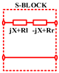
ReqEquivalent ResistanceS-blockseries resonance block
MMutual InductanceT-blockdouble resonance block
LseqEquivalent Secondary InductanceP-blockparallel resonance block
LseEquivalent Secondary Resonant InductanceUPFUnit Power Factor
CsSeries CapacitanceZPAZero Phase Angle
SLCSeries-Parallel CompensatedESREquivalent Series Resistance
H-bridgeFull-bridge InverterLCCL–C Circuit
LCCInductor-Capacitor-CapacitorLInductor
CPLPrincipal Series Variable CapacitorCCapacitor
SLCSeries Inductor-CapacitorLmMutual Inductance
DCDirect CurrentkCoupling Coefficient
ACAlternating CurrentLRXSelf-Inductance in Receiver Side
Foinverters operating resonance frequencyLTXSelf-Inductance in Transmitter Side
ωoOperation’s resonance frequencyRviInternal Resistance
tpgate pulse’s phase shift time delayXmMagnetizing Reactance
Lpeqprinciple equivalent inductanceS/SPSeries/Series-Parallel
RlLoad resistanceS-LCSeries-Inductor-Capacitor
Ptrate of Power transferS-CLCSeries-Capacitor-Inductor-Capacitor
Pmrate of Average power transferCLC-SCapacitor-Inductor-Capacitor-Series
Iltrack currentLCL-SInductor-Capacitor-Inductor-Series
Issecondary track currentLCC-SInductor-Capacitor-Capacitor-Series
LcCharging inductanceLCC-PInductor-Capacitor-Capacitor-Parallel
THDTotal Harmonic DistortionLCL-LCLInductor-Capacitor-Inductor-Capacitor-Series
EMCElectromagnetic CompatibilityLCC-LCCInductor-Capacitor-Capacitor-Inductor-Capacitor
MHzMegahertzCLCcapacitor-inductor-capacitor
CpImpedance Transformation CapacitanceLCLinductor-capacitor-inductor
C1Resonance Series CapacitorLCCinductor-capacitor-capacitor
LinEquivalent InductanceLfprimary resonant inductance
RinEquivalent ResistanceLf1secondary resonant inductance
Class-EA type of power amplifier circuit designed for high-efficiency power amplificationCccompensation capacitor
SAESociety of Automotive EngineersCsseries resonant capacitor
FTFinemetCxresonant capacitor for the primary or secondary side
MPPMetal Powder CoreDIPTsdynamic inductive power transfer systems
EMIElectromagnetic InterferenceHFhigh frequency
EMFElectromagnetic FieldsOLEVsOn-Line Electric Vehicles
SARSpecific Absorption RateRIPTResonant Inductive Power Transfer
WEVCSWireless Electric Vehicle Charging SystemsICNIRPInternational Commission on Non-Ionizing Radiation Protection
IECInternational Electro-technical CommissionISECIndependent self EMF cancel
HBSEHazard-based Safety EngineeringMTSRMultiple Transmitter Single Receiver
ULUnderwriters LaboratoriesSTMRSingle Transmitter Multiple-Receiver

References

  1. Kiani, M.; Ghaffari, A.; Fazel, S. Wireless power transfer technologies for electric vehicles: A comprehensive review. IEEE Trans. Veh. Technol. 2019, 68, 6–19. [Google Scholar]
  2. Batra, T.; Singh, B. Recent advances in wireless power transfer for electric vehicles: A review. Renew. Sustain. Energy Rev. 2020, 119, 109555. [Google Scholar]
  3. Sun, J.; Chen, Y.; Cheng, L.; Zhang, Q. A review of dynamic wireless charging of electric vehicles: Technology, infrastructure and control. Renew. Sustain. Energy Rev. 2019, 111, 158–169. [Google Scholar]
  4. Kim, H.; Kim, D.; Cho, G. Design of a high-efficiency wireless power transfer system for electric vehicle charging using high-order compensation. Energies 2020, 13, 2933. [Google Scholar]
  5. Zhang, X.; Jiao, Y.; Wu, B.; Deng, J. A comprehensive review on dynamic wireless power transfer for electric vehicles. J. Energy Storage 2020, 31, 101628. [Google Scholar]
  6. Mongeon, P.; Paul-Hus, A. The Journal Coverage of Web of Science and Scopus: A Comparative Analysis. Scientometrics 2016, 106, 213–228. [Google Scholar] [CrossRef]
  7. Mok, K.Y.; Shen, G.Q.; Yang, J. Stakeholder Management Studies in Mega Construction Projects: A Review and Future Directions. Int. J. Proj. Manag. 2015, 33, 446–457. [Google Scholar] [CrossRef]
  8. Yao, Y.; Zhao, B.; Zhao, J.; Shu, F.; Wu, Y.; Cheng, X. Anti-Jamming Technique for IRS Aided JRC System in Mobile Vehicular Networks. IEEE Trans. Intell. Transp. Syst. 2024. [Google Scholar] [CrossRef]
  9. Oraee, M.; Hosseini, M.R.; Papadonikolaki, E.; Palliyaguru, R.; Arashpour, M. Collaboration in BIM-Based Construction Networks: A Bibliometric-Qualitative Literature Review. Int. J. Proj. Manag. 2017, 35, 1288–1301. [Google Scholar] [CrossRef]
  10. Perianes-Rodriguez, A.; Waltman, L.; Van Eck, N.J. Constructing Bibliometric Networks: A Comparison between Full and Fractional Counting. J. Informetr. 2016, 10, 1178–1195. [Google Scholar] [CrossRef]
  11. Chen, C. CiteSpace: A Practical Guide for Mapping Scientific Literature; Nova Science Publishers: Hauppauge, NY, USA, 2016. [Google Scholar]
  12. Li, G.; Luo, T.; Song, Y. Climate Change Mitigation Efficiency of Electric Vehicle Charging Infrastructure in China: From the Perspective of Energy Transition and Circular Economy. Resour. Conserv. Recycl. 2021, 179, 106048. [Google Scholar] [CrossRef]
  13. Liang, J.; Lu, Y.; Wang, F.; Feng, J.; Pi, D.; Yin, G.; Li, Y. ETS-Based Human–Machine Robust Shared Control Design Considering the Network Delays. IEEE Trans. Autom. Sci. Eng. 2024. [Google Scholar] [CrossRef]
  14. Liang, J.; Feng, J.; Lu, Y.; Yin, G.; Zhuang, W.; Mao, X. A Direct Yaw Moment Control Framework Through Robust T-S Fuzzy Approach Considering Vehicle Stability Margin. IEEE/ASME Trans. Mechatron. 2024, 29, 166–178. [Google Scholar] [CrossRef]
  15. Jeong, S.; Jang, Y.J.; Kum, D.; Lee, M.S. Charging Automation for Electric Vehicles: Is a Smaller Battery Good for the Wireless Charging Electric Vehicles? IEEE Trans. Autom. Sci. Eng. 2018, 16, 486–497. [Google Scholar] [CrossRef]
  16. Ellingsen, L.A.-W.; Singh, B.; Strømman, A.H. The Size and Range Effect: Lifecycle Greenhouse Gas Emissions of Electric Vehicles. Environ. Res. Lett. 2016, 11, 054010. [Google Scholar] [CrossRef]
  17. Wang, C.; Wang, Y.; Wang, K.; Dong, Y.; Yang, Y. An Improved Hybrid Algorithm Based on Biogeography/Complex and Metropolis for Many-Objective Optimization. Math. Probl. Eng. 2017, 2017, 2462891. [Google Scholar] [CrossRef]
  18. The University of Sheffield Scientists Develop Pioneering New Spray-on Solar Cells. Available online: https://phys.org/news/2014-08-scientists-spray-on-solar-cells.html (accessed on 16 November 2021).
  19. Amjad, S.; Neelakrishnan, S.; Rudramoorthy, R. Review of Design Considerations and Technological Challenges for Successful Development and Deployment of Plug-in Hybrid Electric Vehicles. Renew. Sustain. Energy Rev. 2010, 14, 1104–1110. [Google Scholar] [CrossRef]
  20. Wang, Y.; Sun, R.; Cheng, Q.; Ochieng, W.Y. Measurement Quality Control Aided Multisensor System for Improved Vehicle Navigation in Urban Areas. IEEE Trans. Ind. Electron. 2024, 71, 6407–6417. [Google Scholar] [CrossRef]
  21. Ren, Y.; Lan, Z.; Liu, L.; Yu, H. EMSIN: Enhanced Multi-Stream Interaction Network for Vehicle Trajectory Prediction. IEEE Trans. Fuzzy Syst. 2024. [Google Scholar] [CrossRef]
  22. Stankiewicz, J.M.; Choroszucho, A. Comparison of the Efficiency and Load Power in Periodic Wireless Power Transfer Systems with Circular and Square Planar Coils. Energies 2021, 14, 4975. [Google Scholar] [CrossRef]
  23. Zhang, W.; Wong, S.C.; Tse, C.; Chen, Q. Analysis and Comparison of Secondary Series- and Parallel-Compensated Inductive Power Transfer Systems Operating for Optimal Efficiency and Load-Independent Voltage-Transfer Ratio. IEEE Trans. Power Electron. 2014, 29, 2979–2990. [Google Scholar] [CrossRef]
  24. Luo, G.; Shao, C.; Cheng, N.; Zhou, H.; Zhang, H.; Yuan, Q.; Li, J. EdgeCooper: Network-Aware Cooperative LiDAR Perception for Enhanced Vehicular Awareness. IEEE J. Sel. Areas Commun. 2024, 42, 207–222. [Google Scholar] [CrossRef]
  25. Kkelis, G.; Yates, D.C.; Mitcheson, P.D. Comparison of Current Driven Class-D and Class-E Half-Wave Rectifiers for 6.78 MHz High Power IPT Applications. In Proceedings of the 2015 IEEE Wireless Power Transfer Conference (WPTC), Boulder, CO, USA, 13–15 May 2015; Institute of Electrical and Electronics Engineers (IEEE): Piscataway, NJ, USA, 2015; pp. 1–4. [Google Scholar]
  26. Kazimierczuk, M.; Jozwik, J. Resonant DC/DC Converter with Class-E Inverter and Class-E Rectifier. IEEE Trans. Ind. Electron. 1989, 36, 468–478. [Google Scholar] [CrossRef]
  27. Bac, N.X.; Vilathgamuwa, D.M.; Madawala, U.K. A SiC-Based Matrix Converter Topology for Inductive Power Transfer system. IEEE Trans. Power Electron. 2014, 29, 4029–4038. [Google Scholar]
  28. Moghaddami, M.; Sarwat, A.I. Single-Phase Soft-Switched AC–AC Matrix Converter with Power Controller for Bidirectional Inductive Power Transfer Systems. IEEE Trans. Ind. Appl. 2018, 54, 3760–3770. [Google Scholar] [CrossRef]
  29. Moghaddami, M.; Anzalchi, A.; Sarwat, A.I. Single-Stage Three-Phase AC–AC Matrix Converter for Inductive Power Transfer Systems. IEEE Trans. Ind. Electron. 2016, 63, 6613–6622. [Google Scholar] [CrossRef]
  30. Li, H.L.; Hu, A.P.; Covic, G.A. A Direct AC–AC Converter for Inductive Power- Transfer systems. IEEE Trans. Power Electron. 2012, 27, 661–668. [Google Scholar] [CrossRef]
  31. Li, M.; Wang, T.; Chu, F.; Han, Q.; Qin, Z.; Zuo, M.J. Scaling-Basis Chirplet Transform. IEEE Trans. Ind. Electron. 2021, 68, 8777–8788. [Google Scholar] [CrossRef]
  32. Yates, D.C.; Aldhaher, S.; Mitcheson, P.D. A 100-W 94% Efficient 6-MHz SiC Class E Inverter with a Sub 2-W GaN Resonant Gate Drive for IPT. In Proceedings of the 2016 IEEE Wireless Power Transfer Conference (WPTC), Aveiro, Portugal, 5–6 May 2016; Institute of Electrical and Electronics Engineers (IEEE): Piscataway, NJ, USA, 2016; pp. 1–3. [Google Scholar]
  33. Bai, X.; Xu, M.; Li, Q.; Yu, L. Trajectory-battery integrated design and its application to orbital maneuvers with electric pump-fed engines. Adv. Space Res. 2022, 70, 825–841. [Google Scholar] [CrossRef]
  34. Ju, Y.; Liu, W.; Zhang, Z.; Zhang, R. Distributed Three-Phase Power Flow for AC/DC Hybrid Networked Microgrids Considering Converter Limiting Constraints. IEEE Trans. Smart Grid 2022, 13, 1691–1708. [Google Scholar] [CrossRef]
  35. Cirimele, V.; Smiai, O.; Guglielmi, P.; Bellotti, F.; Berta, R.; De Gloria, A. Maximizing Power Transfer for Dynamic Wireless Charging Electric Vehicles. In Electrical Engineering and Applied Computing; Springer Science and Business Media LLC: Berlin/Heidelberg, Germany, 2018; pp. 59–65. [Google Scholar]
  36. Lu, J.-H.; Lin, P.; Li, X.-K.; Li, W.-J.; Zhu, G.-R.; Wong, S.-C.; Jiang, J.; Liu, F. Research on Seamless Transfer from CC to CV Modes for IPT EV Charging System Based on Double-Sided LCC Compensation Network. In Proceedings of the 2016 IEEE Energy Conversion Congress and Exposition (ECCE), Milwaukee, WI, USA, 18–22 September 2016; Institute of Electrical and Electronics Engineers (IEEE): Piscataway, NJ, USA, 2016; pp. 1–6. [Google Scholar]
  37. Yao, Y.; Liu, X.; Wang, Y.; Xu, D. Modified Parameter Tuning Method for LCL/P Compensation Topology Featured with load-independent and LCT-unconstrained Output Current. IET Power Electron. 2018, 11, 1483–1491. [Google Scholar] [CrossRef]
  38. Li, R.; Pan, Y.; Zhang, X.; Dai, W.; Liu, B.; Li, J. Mechanical safety prediction of a battery-pack system under low speed frontal impact via machine learning. Eng. Anal. Bound. Elem. 2024, 160, 65–75. [Google Scholar] [CrossRef]
  39. Sohn, Y.H.; Choi, B.H.; Lee, E.S.; Lim, G.C.; Cho, G.-H.; Rim, C.T. General Unified Analyses of Two-Capacitor Inductive Power Transfer Systems: Equivalence of Current-Source SS and SP Compensations. IEEE Trans. Power Electron. 2015, 30, 6030–6045. [Google Scholar] [CrossRef]
  40. Moghaddami, M.; Sarwat, A. Self-Tuned Single-Phase AC-AC Converter for Bidirectional Inductive Power Transfer Systems. In Proceedings of the 2017 IEEE Industry Applications Society Annual Meeting, Cincinnati, OH, USA, 1–5 October 2017; Institute of Electrical and Electronics Engineers (IEEE): Piscataway, NJ, USA, 2017; pp. 1–6. [Google Scholar]
  41. Mishima, T. A Time-Sharing Current-Fed ZCS High Frequency Inverter Based Resonant DC-DC Converter with Si-IGBT/SiC-SBD Hybrid Module for Inductive Power Transfer applications. IEEE J. Emerg. Sel. Top. Power Electron. 2019, 8, 506–516. [Google Scholar] [CrossRef]
  42. Narayanamoorthi, R.; Juliet, A.V.; Chokkalingam, B. Cross Interference Minimization and Simultaneous Wireless Power Transfer to Multiple Frequency Loads Using Frequency Bifurcation Approach. IEEE Trans. Power Electron. 2019, 34, 10898–10909. [Google Scholar] [CrossRef]
  43. Liu, M.; Qiao, Y.; Liu, S.; Ma, C. Analysis and Design of a Robust Class E2 DC–DC Converter for Megahertz Wireless Power transfer. IEEE Trans. Power Electron. 2017, 32, 2835–2845. [Google Scholar] [CrossRef]
  44. Liu, M.; Fu, M.; Ma, C. Parameter Design for a 6.78-MHz Wireless Power Transfer System Based on Analytical Derivation of Class E Current-Driven Rectifier. IEEE Trans. Power Electron. 2016, 31, 4280–4291. [Google Scholar] [CrossRef]
  45. Nagashima, T.; Wei, X.; Suetsugu, T.; Kazimierczuk, M.K.; Sekiya, H. Waveform Equations, Output Power, and Power Con-Version Efficiency for Class-E Inverter Out- Side Nominal operation. IEEE Trans. Ind. Electron. 2014, 61, 1799–1810. [Google Scholar] [CrossRef]
  46. Feng, J.; Yao, Y.; Liu, Z.; Liu, Z. Electric vehicle charging stations’ installing strategies: Considering government subsidies. Appl. Energy 2024, 370, 123552. [Google Scholar] [CrossRef]
  47. Houran, M.A.; Yang, X.; Chen, W.; Samizadeh, M. Wireless Power Transfer: Critical Review of Related Standards. In Proceedings of the 2018 International Power Electronics Conference (IPEC-Niigata 2018-ECCE Asia), Niigata, Japan, 20–24 May 2018; Institute of Electrical and Electronics Engineers (IEEE): Piscataway, NJ, USA, 2018; pp. 1062–1066. [Google Scholar]
  48. Zhang, R.; Li, X.; Sun, C.; Yang, S.; Tian, Y.; Tian, J. State of Charge and Temperature Joint Estimation Based on Ultrasonic Reflection Waves for Lithium-Ion Battery Applications. Batteries 2023, 9, 335. [Google Scholar] [CrossRef]
  49. Feng, J.; Wang, Y.; Liu, Z. Joint impact of service efficiency and salvage value on the manufacturer’s shared vehicle-type strategies. RAIRO-Oper. Res. 2024, 58, 2261–2287. [Google Scholar] [CrossRef]
  50. Moghaddami, M.; Sundararajan, A.; Sarwat, A.I. A Self-Tuning Variable Frequency Control for Multi-Level Contactless Electric Vehicle Charger. In Proceedings of the 2016 IEEE International Conference on Power Electronics, Drives and Energy Systems (PEDES), Trivandrum, India, 14–17 December 2016; Institute of Electrical and Electronics Engineers (IEEE): Piscataway, NJ, USA, 2016; pp. 1–5. [Google Scholar]
  51. Zou, B.; Xiong, M.; Wang, H.; Ding, W.; Jiang, P.; Hua, W.; Zhang, Y.; Zhang, L.; Wang, W.; Tan, R. A Deep Learning Approach for State-of-Health Estimation of Lithium-Ion Batteries Based on a Multi-Feature and Attention Mechanism Collaboration. Batteries 2023, 9, 329. [Google Scholar] [CrossRef]
  52. Chou, J.-H.; Wang, F.-K.; Lo, S.-C. A Novel Fine-Tuning Model Based on Transfer Learning for Future Capacity Prediction of Lithium-Ion Batteries. Batteries 2023, 9, 325. [Google Scholar] [CrossRef]
  53. Triviño, A.; González-González, J.; Aguado, J. Wireless Power Transfer Technologies Applied to Electric Vehicles: A Review. Energies 2021, 14, 1547. [Google Scholar] [CrossRef]
  54. Covic, G.A.; Boys, J.T. Modern Trends in Inductive Power Transfer for Transportation Applications. IEEE J. Emerg. Sel. Top. Power Electron. 2013, 1, 28–41. [Google Scholar] [CrossRef]
  55. Foote, A.; Onar, O.C. A Review of High-Power Wireless Power Transfer. In Proceedings of the 2017 IEEE Transportation Electrification Conference and Expo (ITEC), Chicago, IL, USA, 22–24 June 2017; Institute of Electrical and Electronics Engineers (IEEE): Piscataway, NJ, USA, 2017; pp. 234–240. [Google Scholar]
  56. Lee, S.; Huh, J.; Park, C.; Choi, N.-S.; Cho, G.-H.; Rim, C.-T. On-Line Electric Vehicle Using Inductive Power Transfer System. In Proceedings of the 2010 IEEE Energy Conversion Congress and Exposition, Atlanta, GA, USA, 12–16 September 2010; IEEE: Piscataway, NJ, USA, 2010; pp. 1598–1601. [Google Scholar]
  57. Kim, J.H.; Lee, B.S.; Lee, J.H.; Lee, S.H.; Park, C.B.; Jung, S.M.; Lee, S.G.; Yi, K.P.; Baek, J. Development of 1-MW Inductive Power Transfer System for a High-Speed Train. IEEE Trans. Ind. Electron. 2015, 62, 6242–6250. [Google Scholar] [CrossRef]
  58. Ahn, J.H.; Lee, B.K. “High-efficiency adaptive-current charging strategy for electric vehicles considering variation of internal resistance of lithium-ion battery. IEEE Trans. Power Electron. 2019, 34, 3041–3052. [Google Scholar] [CrossRef]
  59. Gao, Y.; Zhang, X.; Cheng, Q.; Guo, B.; Yang, J. Classification and review of the charging strategies for commercial lithium-ion batteries. IEEE Access 2019, 7, 43511–43524. [Google Scholar] [CrossRef]
  60. Wang, X.; Xu, J.; Mao, M.; Ma, H. An LCL-based SS compensated WPT converter with wide ZVS range and integrated coil structure. IEEE Trans. Ind. Electron. 2021, 68, 4882–4893. [Google Scholar] [CrossRef]
  61. Shi, K.; Tang, C.; Long, H.; Lv, X.; Wang, Z.; Li, X. Power fluctuation suppression method for EV dynamic wireless charging system based on integrated magnetic coupler. IEEE Trans. Power Electron. 2022, 37, 1118–1131. [Google Scholar] [CrossRef]
  62. Huh, S.; Ahn, D. Two-transmitter wireless power transfer with optimal activation and current selection of transmitters. IEEE Trans. Power Electron. 2018, 33, 4957–4967. [Google Scholar] [CrossRef]
  63. Darvish, P.; Mekhilef, S.; Illias, H.A.B. A novel S-S-LCLCC compensation for three-coil WPT to improve misalignment and energy efficiency stiffness of wireless charging system. IEEE Trans. Power Electron. 2021, 36, 1341–1355. [Google Scholar] [CrossRef]
  64. Tan, L.; Zhang, M.; Wang, S.; Pan, S.; Zhang, Z.; Li, J.; Huang, X. The design and optimization of a wireless power transfer system allowing random access for multiple loads. Energies 2019, 12, 1017. [Google Scholar] [CrossRef]
  65. Wu, L.; Zhang, B.; Zhou, J. Efficiency improvement of the paritytime-symmetric wireless power transfer system for electric vehicle charging. IEEE Trans. Power Electron. 2020, 35, 12497–12508. [Google Scholar] [CrossRef]
  66. Zhou, S.; Mi, C.C. Multi-paralleled LCC reactive power compensation networks and their tuning method for electric vehicle dynamic wireless charging. IEEE Trans. Ind. Electron. 2016, 63, 6546–6556. [Google Scholar] [CrossRef]
  67. Moon, S.C.; Moon, G.W. Wireless power transfer system with an asymmetric four-coil resonator for electric vehicle battery chargers. IEEE Trans. Power Electron. 2016, 31, 6844–6854. [Google Scholar]
  68. Zhong, W.X.; Zhang, C.; Liu, X.; Hui, S.Y.R. A methodology for making a three-coil wireless power transfer system more energy efficient than a two-coil counterpart for extended transfer distance. IEEE Trans. Power Electron. 2015, 30, 933–942. [Google Scholar] [CrossRef]
  69. Li, Y.; Hu, J.; Li, X.; Cheng, K.W.E. A flexible load-independent multi-output wireless power transfer system based on cascaded double Tresonant circuits: Analysis, design and experimental verification. IEEE Trans. Circuits Syst. I Regul. Pap. 2019, 66, 2803–2812. [Google Scholar] [CrossRef]
  70. Cota, K.A.; Gray, P.A.; Pathmanathan, M.; Lehn, P.W. An approach for selecting compensation capacitances in resonance-based EV wireless power transfer systems with switched capacitors. IEEE Trans. Transp. Electrif. 2019, 5, 1004–1014. [Google Scholar] [CrossRef]
  71. Moon, S.; Kim, B.C.; Cho, S.Y.; Ahn, C.H.; Moon, G.W. Analysis and design of a wireless power transfer system with an intermediate coil for high efficiency. IEEE Trans. Ind. Electron. 2014, 61, 5861–5870. [Google Scholar] [CrossRef]
  72. Zhong, W.X.; Xu, D.H.; Hui, R.S.Y. Wireless Power Transfer—Between Distance and Efficiency (CPSS Power Electronics Series); Springer: Berlin, Germany, 2020. [Google Scholar]
  73. Lu, J.; Zhu, G.; Lin, D.; Zhang, Y.; Jiang, J.; Mi, C.C. Unified loadindependent ZPA analysis and design in CC and CV modes of higher order resonant circuits for WPT systems. IEEE Trans. Transp. Electrif. 2019, 5, 977–987. [Google Scholar] [CrossRef]
  74. Yang, L.; Li, X.; Liu, S.; Xu, Z.; Cai, C. Analysis and design of an LCCC/S-Compensated WPT system with constant output characteristics for battery charging applications. IEEE J. Emerg. Sel. Top. Power Electron. 2021, 9, 1169–1180. [Google Scholar] [CrossRef]
  75. Sohn, Y.H.; Choi, B.H.; Cho, G.H.; Rim, C.T. Gyrator-based analysis of resonant circuits in inductive power transfer systems. IEEE Trans. Power Electron. 2016, 31, 6824–6843. [Google Scholar] [CrossRef]
  76. Wang, Y.; Mai, J.; Yao, Y.; Xu, D. Analysis and Design of an IPT System Based on S/SP Compensation with Improved Output Voltage Regulation. IEEE Trans. Ind. Inform. 2020, 16, 3256–3266. [Google Scholar] [CrossRef]
  77. Huang, Z.; Fang, Z.; Lam, C.-S.; Mak, P.-I.; Martins, R.P. Cost-Effective Compensation Design for Output Customization and Efficiency Optimization in Series/Series-Parallel Inductive Power Transfer Converter. IEEE Trans. Ind. Electron. 2020, 67, 10356–10365. [Google Scholar] [CrossRef]
  78. Mai, R.; Chen, Y.; Zhang, Y.; Yang, N.; Cao, G.; He, Z. Optimization of the Passive Components for an S-LCC Topology-Based WPT System for Charging Massive Electric Bicycles. IEEE Trans. Ind. Electron. 2018, 65, 5497–5508. [Google Scholar] [CrossRef]
  79. Yao, Y.; Wang, Y.; Liu, X.; Pei, Y.; Xu, D.; Liu, X. Particle Swarm Optimization-Based Parameter Design Method for S/CLC-Compensated IPT Systems Featuring High Tolerance to Misalignment and Load Variation. IEEE Trans. Power Electron. 2015, 34, 5268–5282. [Google Scholar] [CrossRef]
  80. Wang, Y.; Yao, Y.; Liu, X.; Xu, D. S/CLC Compensation Topology Analysis and Circular Coil Design for Wireless Power Transfer. IEEE Trans. Transp. Electrif. 2017, 3, 496–507. [Google Scholar] [CrossRef]
  81. Wang, Y.; Liu, W.; Huangfu, Y. A Primary-Sided CLC Compensated Wireless Power Transfer System Based on the Class D Amplifier. In Proceedings of the IECON 2018—44th Annual Conference of the IEEE Industrial Electronics Society, Washington, DC, USA, 21–23 October 2018; pp. 943–947. [Google Scholar]
  82. Gao, W.; Jiang, L.; Chen, Q.; Ren, X.; Zhang, Z.; Wong, S. Analysis and Design of an Integrated LCL-S Contactless Resonant Converter. In Proceedings of the IEEE Conference on Applied Power Electronics Conference and Exposition, San Antonio, TX, USA, 4–8 March 2018; pp. 3178–3182. [Google Scholar]
  83. Kan, T.; Lu, F.; Nguyen, T.; Mercier, P.P.; Mi, C.C. An Operation Mode Selection Method of Dual-Side Bridge Converters for Efficiency Optimization in Inductive Power Transfer. IEEE Trans. Power Electron. 2020, 35, 9992–9997. [Google Scholar]
  84. Li, Y.; Hu, J.; Li, X.; Mai, R.; Li, Z.; Liu, M.; He, Z. Efficiency Analysis and Optimization Control for Input-Parallel Output-Series Wireless Power Transfer Systems. IIEEE Trans. Power Electron. 2020, 35, 1074–1085. [Google Scholar] [CrossRef]
  85. Lu, J.; Zhu, G.; Wang, H.; Lu, F.; Jiang, J.; Mi, C.C. Sensitivity Analysis of Inductive Power Transfer Systems with Voltage-Fed Compensation Topologies. IEEE Trans. Veh. Technol. 2019, 68, 4502–4513. [Google Scholar] [CrossRef]
  86. Vu, V.; Phan, V.; Dahidah, M.; Pickert, V. Multiple Output Inductive Charger for Electric Vehicles. IIEEE Trans. Power Electron. 2019, 34, 7350–7368. [Google Scholar] [CrossRef]
  87. Yao, Y.; Wang, Y.; Liu, X.; Lin, F.; Xu, D. A Novel Parameter Tuning Method for a Double-Sided LCL Compensated WPT System with Better Comprehensive Performance. IIEEE Trans. Power Electron. 2018, 33, 8525–8536. [Google Scholar] [CrossRef]
  88. Song, K.; Wei, R.; Yang, G.; Zhang, H.; Li, Z.; Huang, X.; Jiang, J.; Zhu, C.; Du, Z. Constant Current Charging and Maximum System Efficiency Tracking for Wireless Charging Systems Employing Dual-Side Control. IEEE Trans. Ind. Appl. 2020, 56, 622–634. [Google Scholar] [CrossRef]
  89. Wang, F.; Zhang, W.; Ye, L.; Guo, J.; Liu, K.; Do, H.T. A Design Method to Implement ZVS for Electric Vehicle Wireless Charging System with Double-Side LCC Compensation. IEEE Trans. Emerg. Sel. Top. Power Electron. 2021, 9, 3791–3801. [Google Scholar] [CrossRef]
  90. Vu, V.B.; Tran, D.H.; Choi, W. Implementation of the Constant Current and Constant Voltage Charge of Inductive Power Transfer Systems with the Double-Sided LCC Compensation Topology for Electric Vehicle Battery Charge Applications. IEEE Trans. Power Electron. 2018, 33, 7398–7410. [Google Scholar] [CrossRef]
  91. Chen, Y.; Kou, Z.; Zhang, Y.; He, Z.; Mai, R.; Cao, G. Hybrid Topology with Configurable Charge Current and Charge Voltage Output-Based WPT Charger for Massive Electric Bicycles. IEEE Trans. Emerg. Sel. Top. Power 2018, 33, 1581–1594. [Google Scholar] [CrossRef]
  92. Yao, Y.; Wang, Y.; Liu, X.; Lu, K.; Xu, D. Analysis and Design of an S/SP Compensated IPT System to Minimize Output Voltage Fluctuation Versus Coupling Coefficient and Load Variation. IEEE Trans. Veh. Technol. 2018, 67, 9262–9272. [Google Scholar] [CrossRef]
  93. Zhang, Y.; Wei, G.; Wang, C.; Yin, Y.; Feng, J.; Na, T.; Song, K.; Zhu, C. A Hybrid Compensation Topology with Constant Current and Constant Voltage Outputs for Wireless Charging System. IEEE Trans. Transp. Electrif. 2022, 9, 2070–2080. [Google Scholar] [CrossRef]
  94. Feng, H.; Dayerizadeh, A.; Lukic, S.M. A Coupling-Insensitive X-Type IPT System for High Position Tolerance. IEEE Trans. Ind. Electron. 2021, 68, 6917–6926. [Google Scholar] [CrossRef]
  95. Mai, J.; Wang, Y.; Yao, Y.; Xu, D. Analysis and Design of High-Misalignment-Tolerant Compensation Topologies with Constant-Current or Constant-Voltage Output for IPT Systems. IEEE Trans. Power Electron. 2021, 36, 2685–2695. [Google Scholar] [CrossRef]
  96. Qu, X.; Han, H.; Wong, S.; Tse, C.K.; Chen, W. Hybrid IPT Topologies with Constant Current or Constant Voltage Output for Battery Charging Applications. IEEE Trans. Power Electron. 2015, 30, 6329–6337. [Google Scholar] [CrossRef]
  97. Wang, D.; Qu, X.; Yao, Y.; Yang, P. Hybrid Inductive-Power-Transfer Battery Chargers for Electric Vehicle Onboard Charging with Configurable Charging Profile. IEEE Trans. Intell. Transp. Syst. 2021, 22, 592–599. [Google Scholar] [CrossRef]
  98. Li, Y.; Xu, Q.; Lin, T.; Hu, J.; He, Z.; Mai, R. Analysis and Design of Load-Independent Output Current or Output Voltage of a Three-Coil Wireless Power Transfer System. IEEE Trans. Transp. Electrif. 2018, 4, 364–375. [Google Scholar] [CrossRef]
  99. Rezazade, S.; Shahirinia, A.; Naghash, R.; Rasekh, N.; Afjei, E. A Novel Efficient Hybrid Compensation Topology for Wireless Power Transfer. IEEE Trans. Ind. Electron. 2022, 70, 2277–2285. [Google Scholar] [CrossRef]
  100. Thenathayalan, D.; Park, J.H. Highly Flexible High-Efficiency Multiple-Resonant Wireless Power Transfer System Using a Controllable Inductor. IEEE Trans. Emerg. Sel. Top. Power Electron. 2019, 7, 1914–1930. [Google Scholar] [CrossRef]
  101. Abdelatty, O.; Wang, X.Y.; Mortazawi, A. Position-Insensitive Wireless Power Transfer Based on Nonlinear Resonant Circuits. IEEE Trans. Microw. Theory Tech. 2019, 67, 3844–3855. [Google Scholar] [CrossRef]
  102. Song, K.; Li, Z.; Jiang, J.; Zhu, C. Constant Current/Voltage Charging Operation for Series-Series and Series-Parallel Compensated Wireless Power Transfer Systems Employing Primary-Side Controller. IEEE Trans. Power Electron. 2018, 33, 8065–8080. [Google Scholar] [CrossRef]
  103. Li, Y.; Hu, J.; Liu, M.; Chen, Y.; Chan, K.W.; He, Z.; Mai, R. Reconfigurable Intermediate Resonant Circuit Based WPT System with Load-Independent Constant Output Current and Voltage for Charging Battery. IEEE Trans. Power Electron. 2019, 34, 1988–1992. [Google Scholar] [CrossRef]
  104. Vaka, R.; Keshri, R.K. Reconfigurable WPT system for load-independent CC and CV output with transmitting-side control. IET Power Electron. 2020, 14, 685–694. [Google Scholar] [CrossRef]
  105. Ji, L.; Wang, L.; Liao, C.; Li, S.; Ma, J. Research and design of automatic alternation between constant-current and constant-voltage modes on the secondary side in wireless charging systems. IET Electr. Power Appl. 2020, 14, 1119–1126. [Google Scholar] [CrossRef]
  106. Liu, S.; Li, X.; Yang, L. Three-coil structure-based WPT system design for electric bike CC and CV charging without communication. IET Electr. Power Appl. 2019, 13, 1318–1327. [Google Scholar] [CrossRef]
  107. Li, W.; Zhao, H.; Li, S.; Deng, J.; Kan, T.; Mi, C.C. Integrated LCC Compensation Topology for Wireless Charger in Electric and Plug-in Electric Vehicles. IEEE Trans. Ind. Electron. 2015, 62, 4215–4225. [Google Scholar] [CrossRef]
  108. Feng, H.; Tavakoli, R.; Onar, O.C.; Pantic, Z. Advances in High-Power Wireless Charging Systems: Overview and Design Considerations. IEEE Trans. Transp. Electrif. 2020, 6, 886–919. [Google Scholar] [CrossRef]
  109. Ramezani, A.; Narimani, M. A New Wireless EV Charging System with Integrated DC–DC Magnetic Element. IEEE Trans. Transp. Electrif. 2019, 5, 1112–1123. [Google Scholar] [CrossRef]
  110. Ramezani, A.; Narimani, M. Optimal Design of Fully Integrated Magnetic Structure for Wireless Charging of Electric Vehicles. IEEE Trans. Transp. Electrif. 2021, 7, 2114–2127. [Google Scholar] [CrossRef]
  111. Kan, T.; Nguyen, T.; White, J.C.; Malhan, R.K.; Mi, C.C. A New Integration Method for an Electric Vehicle Wireless Charging System Using LCC Compensation Topology: Analysis and Design. IEEE Trans. Power Electron. 2017, 32, 1638–1650. [Google Scholar] [CrossRef]
  112. Rasekh, N.; Mirsalim, M. Evaluation study on an integration method for a DDQP using LCC and series compensation topologies for inductive power transfer. IET Electr. Power Appl. 2018, 12, 1320–1327. [Google Scholar] [CrossRef]
  113. International Commission on Non-Ionizing Radiation Protection (ICNIRP). Guidelines for Limiting Exposure to Time-Varying Electric and Magnetic Fields (1 Hz to 100 KHz). Health Phys. 2010, 99, 818–836. [Google Scholar] [CrossRef]
  114. International Commission on Non-Ionizing Radiation Protection (ICNIRP). Guidelines for limiting exposure to time-varying electric, magnetic, and electromagnetic fields (up to 300 GHz). Health Phys. 1998, 74, 494–522. [Google Scholar]
  115. Mohamed, A.A.S.; Shaier, A.A. Shielding Techniques of IPT System for Electric Vehicles’ Stationary Charging. In Electric Vehicle Integration in a Smart Microgrid Environment; CRC Press: Boca Raton, FL, USA, 2021; pp. 279–293. [Google Scholar]
  116. Choi, S.Y.; Gu, B.W.; Lee, S.W.; Lee, W.Y.; Huh, J.; Rim, C.T. Generalized Active EMF Cancel Methods for Wireless Electric Vehicles. IEEE Trans. Power Electron. 2013, 29, 5770–5783. [Google Scholar] [CrossRef]
  117. Kim, S.; Park, H.-H.; Kim, J.; Kim, J.; Ahn, S. Design and Analysis of a Resonant Reactive Shield for a Wireless Power Electric Vehicle. IEEE Trans. Microw. Theory Tech. 2014, 62, 1057–1066. [Google Scholar] [CrossRef]
  118. Hui, S.Y.R.; Zhong, W.; Lee, C.K. A Critical Review of Recent Progress in Mid-Range Wireless Power Transfer. IEEE Trans. Power Electron. 2013, 29, 4500–4511. [Google Scholar] [CrossRef]
  119. Zhang, J.; Yuan, X.; Wang, C.; He, Y. Comparative Analysis of Two-Coil and Three-Coil Structures for Wireless Power Transfer. IEEE Trans. Power Electron. 2016, 32, 341–352. [Google Scholar] [CrossRef]
  120. Arakawa, T.; Goguri, S.; Krogmeier, J.V.; Kruger, A.; Love, D.J.; Mudumbai, R.; Swabey, M.A. Optimizing Wireless Power Transfer from Multiple Transmit Coils. IEEE Access 2018, 6, 23828–23838. [Google Scholar] [CrossRef]
  121. Bi, Z.; Kan, T.; Mi, C.C.; Zhang, Y.; Zhao, Z.; Keoleian, G.A. A review of wireless power transfer for electric vehicles: Prospects to enhance sustainable mobility. Appl. Energy 2016, 179, 413–425. [Google Scholar] [CrossRef]
  122. Lu, F.; Zhang, H.; Hofmann, H.; Mi, C.C. A Dynamic Charging System with Reduced Output Power Pulsation for Electric Vehicles. IEEE Trans. Ind. Electron. 2016, 63, 6580–6590. [Google Scholar] [CrossRef]
  123. Suh, N.; Cho, D.; Rim, C. Design of On-Line Electric Vehicle (OLEV). In Global Product Development; Springer: Berlin/Heidelberg, Germany, 2011; pp. 3–8. [Google Scholar]
  124. Sun, L.; Ma, D.; Tang, H. A review of recent trends in wireless power transfer technology and its applications in electric vehicle wireless charging. Renew. Sustain. Energy Rev. 2018, 91, 490–503. [Google Scholar] [CrossRef]
  125. Ko, Y.D.; Jang, Y.J. The Optimal System Design of the Online Electric Vehicle Utilizing Wireless Power Transmission Technology. IEEE Trans. Intell. Transp. Syst. 2013, 14, 1255–1265. [Google Scholar] [CrossRef]
  126. García-Vázquez, C.A.; Llorens-Iborra, F.; Fernández-Ramírez, L.M.; Sánchez-Sainz, H.; Jurado, F. Comparative study of dynamic wireless charging of electric vehicles in motorway, highway and urban stretches. Energy 2017, 137, 42–57. [Google Scholar] [CrossRef]
  127. Choi, S.Y.; Gu, B.W.; Jeong, S.Y.; Rim, C.T. Advances in Wireless Power Transfer Systems for Roadway-Powered Electric Vehicles. IEEE J. Emerg. Sel. Top. Power Electron. 2014, 3, 18–36. [Google Scholar] [CrossRef]
  128. Mi, C.C.; Buja, G.; Choi, S.Y.; Rim, C.T. Modern Advances in Wireless Power Transfer Systems for Roadway Powered Electric Vehicles. IEEE Trans. Ind. Electron. 2016, 63, 6533–6545. [Google Scholar] [CrossRef]
  129. Huh, J.; Lee, S.W.; Lee, W.Y.; Cho, G.H.; Rim, C.T. Narrow-Width Inductive Power Transfer System for Online Electrical Vehicles. IEEE Trans. Power Electron. 2011, 26, 3666–3679. [Google Scholar] [CrossRef]
  130. Song, K.; Koh, K.E.; Zhu, C.; Jiang, J.; Wang, C.; Huang, X. A Review of Dynamic Wireless Power Transfer for In-Motion Electric Vehicles. In Wireless Power Transfer-Fundamentals and Technologies; BoD–Books on Demand: Norderstedt, Germany, 2016; pp. 109–128. [Google Scholar]
  131. Choi, S.; Huh, J.; Lee, W.Y.; Lee, S.W.; Rim, C.T. New Cross-Segmented Power Supply Rails for Roadway-Powered Electric Vehicles. IEEE Trans. Power Electron. 2013, 28, 5832–5841. [Google Scholar] [CrossRef]
  132. Miller, J.M.; Jones, P.; Li, J.-M.; Onar, O.C. ORNL Experience and Challenges Facing Dynamic Wireless Power Charging of EV’s. IEEE Circuits Syst. Mag. 2015, 15, 40–53. [Google Scholar] [CrossRef]
  133. Gil, A.; Taiber, J. A Literature Review in Dynamic Wireless Power Transfer for Electric Vehicles: Technology and Infrastructure Integration Challenges. In Sustainable Automotive Technologies; Springer: Cham, Switzerland, 2013; pp. 289–298. [Google Scholar]
  134. Lee, K.; Pantic, Z.; Lukic, S. Reflexive Field Containment in Dynamic Inductive Power Transfer Systems. IEEE Trans. Power Electron. 2013, 29, 4592–4602. [Google Scholar] [CrossRef]
  135. Chen, L.; Nagendra, G.; Boys, J.T.; Covic, G.A. Double-Coupled Systems for IPT Roadway Applications. IEEE J. Emerg. Sel. Top. Power Electron. 2014, 3, 37–49. [Google Scholar] [CrossRef]
  136. Miller, J.M.; Onar, O.C.; White, C.; Campbell, S.; Coomer, C.; Seiber, L.; Sepe, R.; Steyerl, A. Demonstrating Dynamic Wireless Charging of an Electric Vehicle: The Benefit of Electrochemical Capacitor Smoothing. IEEE Power Electron. Mag. 2014, 1, 12–24. [Google Scholar] [CrossRef]
  137. Shin, S.; Shin, J.; Kim, Y.; Lee, S.; Song, B.; Jung, G.; Jeon, S. Hybrid inverter segmentation control for Online Electric Vehicle. In Proceedings of the 2012 IEEE International Electric Vehicle Conference, Greenville, SC, USA, 4–8 March 2012; pp. 1–6. [Google Scholar]
  138. Nagendra, G.; Chen, L.; Covic, G.A.; Boys, J.T. Detection of EVs on IPT Highways. IEEE J. Emerg. Sel. Top. Power Electron. 2014, 2, 584–597. [Google Scholar] [CrossRef]
  139. Jang, G.C.; Jeong, S.Y.; Kwak, H.G.; Rim, C.T. Metal object detection circuit with non-overlapped coils for wireless EV chargers. In Proceedings of the 2016 IEEE 2nd Annual Southern Power Electronics Conference (SPEC), Auckland, New Zealand, 5–8 December 2016; pp. 1–6. [Google Scholar]
  140. Simonazzi, M.; Sandrolini, L.; Mariscotti, A. Receiver–Coil Location Detection in a Dynamic Wireless Power Transfer System for Electric Vehicle Charging. Sensors 2022, 22, 2317. [Google Scholar] [CrossRef]
  141. Deng, Q.; Liu, J.; Czarkowski, D.; Bojarski, M.; Chen, J.; Zhou, H.; Hu, W. Edge position detection of on-line vehicles with segmental wireless power supply. IEEE Trans. Veh. Technol. 2016, 66, 3610–3621. [Google Scholar] [CrossRef]
  142. Beh, H.Z.Z.; Covic, G.A.; Boys, J.T. Wireless Fleet Charging System for Electric Bicycles. IEEE J. Emerg. Sel. Top. Power Electron. 2014, 3, 75–86. [Google Scholar] [CrossRef]
  143. Nagendra, G.R.; Boys, J.T.; Covic, G.A.; Riar, B.S.; Sondhi, A. Design of a double coupled IPT EV highway. In Proceedings of the IECON 2013—39th Annual Conference of the IEEE Industrial Electronics Society, Vienna, Austria, 10–13 November 2013; pp. 4606–4611. [Google Scholar]
  144. Tan, L.; Zhao, W.; Liu, H.; Li, J.; Huang, X. Design and Optimization of Ground-Side Power Transmitting Coil Parameters for EV Dynamic Wireless Charging System. IEEE Access 2020, 8, 74595–74604. [Google Scholar] [CrossRef]
  145. Buja, G.; Bertoluzzo, M.; Dashora, H.K. Lumped Track Layout Design for Dynamic Wireless Charging of Electric Vehicles. IEEE Trans. Ind. Electron. 2016, 63, 6631–6640. [Google Scholar] [CrossRef]
  146. Sampath, J.P.K.; Vilathgamuwa, D.M.; Alphones, A. Efficiency Enhancement for Dynamic Wireless Power Transfer System with Segmented Transmitter Array. IEEE Trans. Transp. Electrif. 2015, 2, 76–85. [Google Scholar] [CrossRef]
  147. Zhang, W.; Wong, S.-C.; Tse, C.K.; Chen, Q. An Optimized Track Length in Roadway Inductive Power Transfer Systems. IEEE J. Emerg. Sel. Top. Power Electron. 2014, 2, 598–608. [Google Scholar] [CrossRef]
  148. Wang, H.; Cheng, K. An Improved and Integrated Design of Segmented Dynamic Wireless Power Transfer for Electric Vehicles. Energies 2021, 14, 1975. [Google Scholar] [CrossRef]
  149. Li, X.; Hu, J.; Wang, H.; Dai, X.; Sun, Y. A New Coupling Structure and Position Detection Method for Segmented Control Dynamic Wireless Power Transfer Systems. IEEE Trans. Power Electron. 2020, 35, 6741–6745. [Google Scholar] [CrossRef]
  150. Zhu, Q.; Wang, L.; Guo, Y.; Liao, C.; Li, F. Applying LCC Compensation Network to Dynamic Wireless EV Charging System. IEEE Trans. Ind. Electron. 2016, 63, 6557–6567. [Google Scholar] [CrossRef]
  151. Feng, H.; Cai, T.; Duan, S.; Zhao, J.; Zhang, X.; Chen, C. An LCC-Compensated Resonant Converter Optimized for Robust Reaction to Large Coupling Variation in Dynamic Wireless Power Transfer. IEEE Trans. Ind. Electron. 2016, 63, 6591–6601. [Google Scholar] [CrossRef]
  152. SAE J2954; Wireless Power Transfer for Light-Duty Plug-in/Electric Vehicles and Alignment Methodology. SAE International: Warrendale, PA, USA, 2020.
  153. Onar, O.C.; Campbell, S.L.; Seiber, L.E.; White, C.P.; Chinthavali, M. A high-power wireless charging system development and integration for a Toyota RAV4 electric vehicle. In Proceedings of the 2016 IEEE Transportation Electrification Conference and Expo (ITEC), Dearborn, MI, USA, 27–29 June 2016; pp. 1–8. [Google Scholar]
  154. Shin, J.; Shin, S.; Kim, Y.; Ahn, S.; Lee, S.; Jung, G.; Jeon, S.-J.; Cho, D.-H. Design and Implementation of Shaped Magnetic-Resonance-Based Wireless Power Transfer System for Roadway-Powered Moving Electric Vehicles. IEEE Trans. Ind. Electron. 2013, 61, 1179–1192. [Google Scholar] [CrossRef]
  155. Zaheer, A.; Covic, G.A.; Kacprzak, D. A Bipolar Pad in a 10-kHz 300-W Distributed IPT System for AGV Applications. IEEE Trans. Ind. Electron. 2013, 61, 3288–3301. [Google Scholar] [CrossRef]
  156. Li, Z.; Tang, M.; Xie, B.; Zhu, Y.; Guo, X.; Sun, H. A Study of Magnetic Coupling Characteristics of Dual Receiver Coil for Dynamic Wireless Power Transfer. IEEE Access 2022, 10, 70516–70525. [Google Scholar] [CrossRef]
  157. Fu, M.; Zhang, T.; Ma, C.; Zhu, X. Efficiency and Optimal Loads Analysis for Multiple-Receiver Wireless Power Transfer Systems. IEEE Trans. Microw. Theory Tech. 2015, 63, 801–812. [Google Scholar] [CrossRef]
  158. Fu, M.; Zhang, T.; Zhu, X.; Luk, P.C.-K.; Ma, C. Compensation of Cross Coupling in Multiple-Receiver Wireless Power Transfer Systems. IEEE Trans. Ind. Inform. 2016, 12, 474–482. [Google Scholar] [CrossRef]
  159. Diekhans, T.; De Doncker, R.W. A Dual-Side Controlled Inductive Power Transfer System Optimized for Large Coupling Factor Variations and Partial Load. IEEE Trans. Power Electron. 2015, 30, 6320–6328. [Google Scholar] [CrossRef]
  160. Pakhaliuk, B.; Husev, O.; Shevchenko, V.; Veligorskyi, O.; Kroics, K. Novel Inductive Power Transfer Approach Based on Z-Source Network with Compensation Circuit. In Proceedings of the 2018 IEEE 38th International Conference on Electronics and Nanotechnology (ELNANO), Kyiv, Ukraine, 24–26 April 2018; pp. 699–704. [Google Scholar]
  161. Xia, C.; Liu, Y.; Lin, K.; Xie, G. Model and Frequency Control for Three-Phase Wireless Power Transfer System. Math. Probl. Eng. 2016, 2016, 3853146. [Google Scholar] [CrossRef]
  162. Khandaker, M.R.A.; Wong, K.-K.; Zhang, Y.; Zheng, Z. Probabilistically Robust SWIPT for Secrecy MISOME Systems. IEEE Trans. Inf. Forensics Secur. 2016, 12, 211–226. [Google Scholar] [CrossRef]
  163. Bosshard, R.; Kolar, J.W. Inductive power transfer for electric vehicle charging: Technical challenges and tradeoffs. IEEE Power Electron. Mag. 2016, 3, 22–30. [Google Scholar] [CrossRef]
  164. Rim, C.T. Practical Design of Wireless Electric Vehicles: Dynamic & Stationary Charging Technologies. 2017. Available online: https://www.researchgate.net/profile/Chun-Rim (accessed on 14 January 2024).
  165. Tomita, K.; Shinoda, R.; Kuroda, T.; Ishikuro, H. 1-W 3.3–16.3-V Boosting Wireless Power Transfer Circuits with Vector Summing Power Controller. IEEE J. Solid-State Circuits 2012, 47, 2576–2585. [Google Scholar] [CrossRef]
  166. Hui, S.; Ho, W. A New Generation of Universal Contactless Battery Charging Platform for Portable Consumer Electronic Equipment. IEEE Trans. Power Electron. 2005, 20, 620–627. [Google Scholar] [CrossRef]
  167. Song, B.-M.; Kratz, R.; Gürol, S. Contactless inductive power pickup system for Maglev applications. In Proceedings of the Conference Record of the 2002 IEEE Industry Applications Conference. 37th IAS Annual Meeting (Cat. No.02CH37344), Pittsburgh, PA, USA, 13–18 October 2002; Volume 3, pp. 1586–1591. [Google Scholar]
  168. Alabakhshizadeh, A.; Midtgård, O.-M.; Boysen, K. Analysis, design and evaluation of a high frequency inductor to reduce manufacturing cost and improve the efficiency of a pv inverter. In Proceedings of the 2013 IEEE 39th Photovoltaic Specialists Conference (PVSC), Tampa, FL, USA, 16–21 June 2013; pp. 2845–2848. [Google Scholar]
  169. Magnetics MPP Cores. Available online: https://www.mag-inc.com/Products/Powder-Cores/MPP-Cores (accessed on 30 September 2022).
  170. De Vries, M. 80 Years of Research at the Philips Natuurkundig Laboratorium (1914–1994): The Role of the Nat. Lab. at Philips; Amsterdam University Press: Amsterdam, The Netherlands, 2005. [Google Scholar]
  171. Fiorillo, F.; Bertotti, G.; Appino, C.; Pasquale, M. Soft magnetic materials. In Wiley Encyclopedia of Electrical and Electronics Engineering; John Wiley & Sons, Inc.: Hoboken, NJ, USA, 2016; pp. 1–42. [Google Scholar]
  172. Duwez, P.; Lin, S.C.H. Amorphous Ferromagnetic Phase in Iron-Carbon-Phosphorus Alloys. J. Appl. Phys. 1967, 38, 4096–4097. [Google Scholar] [CrossRef]
  173. Yoshizawa, Y.; Oguma, S.; Yamauchi, K. New Fe-Based Soft Magnetic Alloys Composed of Ultrafine Grain Structure. J. Appl. Phys. 1988, 64, 6044–6046. [Google Scholar] [CrossRef]
  174. Shokrollahi, H.; Janghorban, K. Soft Magnetic Composite Materials (SMCs). J. Mater. Process. Technol. 2007, 189, 1–12. [Google Scholar] [CrossRef]
  175. Jack, A.G.; Mecrow, B.C.; Dickinson, P.G.; Stephenson, D.; Burdess, J.S.; Fawcett, N.; Evans, J.T. Permanent-Magnet Machines with Powdered Iron Cores and Prepressed Windings. IEEE Trans. Ind. Appl. 2000, 36, 1077–1084. [Google Scholar] [CrossRef]
  176. Hultman, L.O.; Jack, A.G. Soft magnetic composites-materials and applications. In Proceedings of the IEEE International Electric Machines and Drives Conference (IEMDC’03), Madison, WI, USA, 1–4 June 2003; Volume 1, pp. 516–522. [Google Scholar]
  177. Skarrie, H. Design of Powder Core Inductors; Lund University: Lund, Sweden, 2001. [Google Scholar]
  178. Silveyra, J.M.; Ferrara, E.; Huber, D.L.; Monson, T.C. Soft Magnetic Materials for a Sustainable and Electrified World. Science 2018, 362, eaao0195. [Google Scholar] [CrossRef]
  179. Dobrzański, L.A.; Drak, M.; Ziębowicz, B. Materials with Specific Magnetic Properties. J. Achiev. Mater. Manuf. Eng. 2006, 17, 37–40. [Google Scholar]
  180. Lu, Y.; Tan, C.; Ge, W.; Zhao, Y.; Wang, G. Adaptive disturbance observer-based improved super-twisting sliding mode control for electromagnetic direct-drive pump. Smart Mater. Struct. 2023, 32, 17001. [Google Scholar] [CrossRef]
  181. Tan, P.; Yi, F.; Liu, C.; Guo, Y. Modeling of Mutual Inductance for Hexagonal Coils with Horizontal Misalignment in Wireless Power Transfer. In Proceedings of the IEEE Energy Conversion Congress and Exposition (ECCE), Portland, OR, USA, 23–27 September 2018. [Google Scholar]
  182. Tan, P.; Peng, T.; Gao, X.; Zhang, B. Flexible Combination and Switching Control for Robust Wireless Power Transfer System with Hexagonal Array Coil. IEEE Trans. Power Electron. 2021, 36, 3868–3882. [Google Scholar] [CrossRef]
  183. Budhia, M.; Boys, J.T.; Covic, G.A.; Huang, C.-Y. Development of a Single-Sided Flux Magnetic Coupler for Electric Vehicle IPT Charging Systems, Industrial Electronics. IEEE Trans. 2013, 60, 318–328. [Google Scholar]
  184. Zhu, G.; Lorenz, R.D. Achieving low magnetic flux density and low electric field intensity for an inductive wireless power transfer system. In Proceedings of the IEEE Energy Conversion Congress and Exposition (ECCE), Cincinnati, OH, USA, 16–18 February 2017. [Google Scholar]
  185. Mohamed, C.; Guillaume, V.; Alexandru, T. Compliance Assessment of Human Body Exposure to Wireless Power Systems. In Proceedings of the 2nd World Congress on Electrical Engineering and Computer Systems and Science (EECSS’16), Orleans, ON, Canada, 16–17 August 2016. [Google Scholar]
  186. Son, S.; Woo, S.; Kim, H.; Ahn, J.; Huh, S.; Lee, S.; Ahn, S. Shielding Sensor Coil to Reduce the Leakage Magnetic Field and Detect the Receiver Position in Wireless Power Transfer System for Electric Vehicle. Energies 2022, 15, 2493. [Google Scholar] [CrossRef]
  187. IEC 61980-1; Electric Vehicle Wireless Power Transfer (WPT) Systems—Part 1: General Requirements. International Electrotechnical Commission: Geneva, Switzerland, 2020.
  188. IEC 61980-2; Electric Vehicle Wireless Power Transfer (WPT) Systems—Part 2: Specific Requirements for MF-WPT System Communication and Activities. International Electrotechnical Commission: Geneva, Switzerland, 2023.
  189. Lee, S.; Lorenz, R.D. Development and validation of model for 95% efficiency, 220 W wireless power transfer over a 30 cm air-gap. In Proceedings of the IEEE Energy Conversion Congress and Exposition, Atlanta, GA, USA, 12–16 September 2010. [Google Scholar]
  190. Chiang, C. Wireless charging system with magnetic field shaping for electric vehicles. In Proceedings of the World Electric Vehicle Symposium and Exhibition (EVS27), Barcelona, Spain, 17–20 November 2013; pp. 1–5. [Google Scholar]
  191. Wang, Z.; Wei, X. Design Considerations for Wireless Charging Systems with an Analysis of Batteries. Energies 2015, 8, 10664–10683. [Google Scholar] [CrossRef]
  192. Bosshard, R.; Badstubner, U.; Kolar, J.W.; Stevanovic, I. Comparative evaluation of control methods for inductive power transfer. In Proceedings of the 2012 International Conference on Renewable Energy Research and Applications (ICRERA), Nagasaki, Japan, 11–14 November 2012; pp. 1–6. [Google Scholar]
Figure 1. Distribution of Bibliometric Analysis Documents.
Energies 17 03858 g001
Figure 2. List of Co-authorships with Measures for the Top 10 Items for Author.
Energies 17 03858 g002
Figure 3. List of Co-authorships with Measures for the Top 10 Items for Country.
Energies 17 03858 g003
Figure 4. General Layout Structure of Keyword Search Analysis: (a) Density Plot; (b) Cluster Plot.
Energies 17 03858 g004
Figure 5. WPT system with H-Bridge inverter.
Energies 17 03858 g005
Figure 6. Resonance equivalent circuit: (a) LCL-based IPT system; (b) Equivalent circuit built on LCC; (c) Equivalent circuit built on SLC.
Energies 17 03858 g006
Figure 7. WPT system using AC-to-AC matrix converter.
Energies 17 03858 g007
Figure 8. Direct AC-to-AC converter.
Energies 17 03858 g008
Figure 9. Class-E inverter Circuit diagram.
Energies 17 03858 g009
Figure 10. WPT system with Class-E inverter.
Energies 17 03858 g010
Figure 11. High-Efficiency WPT system with Class-E inverter.
Energies 17 03858 g011
Figure 12. Simple circuit of compact high-efficiency topology.
Energies 17 03858 g012
Figure 13. Resonance building blocks with LC components that operate with CC/CV sources and load in a generalized manner.
Energies 17 03858 g013
Figure 14. A generalized block diagram of inductive coupling systems with an ideal T-block segregated from self-inductances.
Energies 17 03858 g014
Figure 15. Four typical methods for compensating for and/or improving the efficiency of WPT systems.
Energies 17 03858 g015
Figure 16. Components of a DIPT device with a single lengthy coil track.
Energies 17 03858 g016
Figure 17. In a DIPT system, single transmitting wire tracks are used: (a) U-type, (b) E-type, (c) I-type, (d) S-type, (e) ultra-thin S-type, and (f) cross-segmented track (X-type).
Energies 17 03858 g017
Figure 18. Sectionalized long transmission track configurations include (a) centralized switching, (b) dispersed switching, and (c) crossed-segmented switching.
Energies 17 03858 g018aEnergies 17 03858 g018b
Figure 19. Supply options for the DIPT system’s segmented transmitter: (A) utilizing a common dc-bus and (B) using a universal HF ac-bus.
Energies 17 03858 g019
Figure 20. Arrangement of reflexive segmentation.
Energies 17 03858 g020
Figure 21. Additional supply solutions for DIPT system segmented transmitters that allow control of individual charging segments: (A) using a common HF inverter with a long magnetic route and (B) utilizing a common HF inverter with transmitter segment series connection.
Energies 17 03858 g021
Figure 22. Schematics of (a) doubled coupled system and (b) intermediate coupler circuit (ICC).
Energies 17 03858 g022
Figure 23. Implementation of receiver pad in DIPT system: (A) single pad and (B) multiple pads.
Energies 17 03858 g023
Figure 24. Research progress and a brief history of soft magnetic materials.
Energies 17 03858 g024
Figure 25. Effect of aluminum shielding on magnetic field density values.
Energies 17 03858 g025
Figure 26. HBSE flowchart.
Energies 17 03858 g026
Table 1. List of Co-authorships with Measures for the Top 10 Items for Organization.
OrganizationCitationsTotal LinksDocuments
SEE, Southeast University, China24712
KLSGT and E In Jiangsu Province, China2668
DECE, San Diego State University, United States892515
SA, North-western Polytechnical University, China63236
SEE, Beijing Jiaotong University, China75210
DEEE, Imperial College London, United Kingdom75217
DEEE, University of Hong Kong, Hong Kong24115
SA, Nanjing University of Science and Technology, China715
CA, Chongqing University, China2607
CEIE, Zhengzhou University of Light Industry, China5705
Table 2. Single and double-resonance blocks for wireless power transfer systems.
Transfer BlockEfficiency and Benefits of Resonance
CV SourceCC Source
Energies 17 03858 i001 η S C V = R 0 R 0 + R S + R v i , R 0 = R l + R r
X 0 + X S = 0
η is same. UPF/ZPA is achieved by adjusting for reactance. Pout can be enhanced and maximized by lowering overall reactance. CV source to CV source
η S C C = R 0 R 0 + R S + Z 0 + Z s Z c i 2 R c i
X 0 + X S = 0
η enhance by lowering loss in Zci (non-ideal CC source). UPF/ZPA is achieved by adjusting for reactance. Pout is increased by reducing overall reactance. CC source to CV source
Energies 17 03858 i002 η P C V = R 0 R S + Z 0 Z P 2 R P + Z 0 Z P + 1 2 R v i
X P =   o r   X 0 + X P = 0
η increase by canceling loss on parasitic Rp and reduce losses in source resistance Rvi. UPF maintained, UPF/ZPA achieved in case of pure resistive load Pout improved by reducing current through Zp CV source to CV source
η P C C = R 0 R S + Z 0 Z P 2 R P + Z 0 Z c i 2 R c i
X P =
η maximized by canceling loss in RP. UPF maintained, UPF/ZPA achieved in case of pure resistive load. Pout is increased when current is reducing through Zp. CC source to CC source
Energies 17 03858 i003 η 7 C V = R 0 R S + Z 0 Z m 2 R m + Z 0 Z m + 1 2 R l v i
X m + X l + X v i = 0
η unchanged. UPF/ZPA unchanged CV-CC mode changed and CC source improved with large Xm
η 7 C C = R 0 C + Z l Z m + ( Z l + Z m ) Z 0 Z m Z c i 2 R c i
X m + X l = 0
η improved by reducing loss in non-ideal CC source Zci. UPF/ZPA changed.
Energies 17 03858 i004 η Γ C V = R 0 R r o + Z 0 + Z r Z m 2 R m + Z 0 + Z r + Z m Z m 2 R v i
X m + X l + X 0 = 0
η improved by reducing loss in non-ideal CV source Zvi. ZPA changed by adding Xm to Zm as Xm increased, the loss in Rvi decreased
η Γ C C = R 0 R r o + Z 0 + Z r Z m 2 R m + Z 0 + Z r Z c i 2 R c i
X m + X l + X 0 = 0
η unchanged CC-CV mode changes, CV source improved. UPF/ZPA changed by adding Xm to Zin.
Energies 17 03858 i005 η T C V = R 0 R r o + Z r + R 0 Z m 2 R m + R 0 + Z r + Z m Z m 2 ( R v i + R l )
X m = X l = X r ; R m = 0
η increased by lowering loss in Zvi and Zl
UPF/ZPA maintained with double resonance
CV-CC, CC-source increased with large Xm
As value of Xm increased the loss in Rvi decreased
η T C C = R 0 R r o + Z r + R 0 Z m 2 R m + R 0 + Z r + Z m Z m 2 R l + ς R c i
X m = X l = X r ; R m = 0
η increased by reducing loss in Zvi and Zl. Maintaining UPF/ZPA by double resonance. CC-CV, CV-source increased with large Xm. As value of Xm increased the loss in Rvi decreased, then η is improved.
Table 3. Hybrid Compensation Topologies.
Topology DiagramParameters
S/SP topology
Energies 17 03858 i006
angular frequency:
ω = 1 L p + ω 2 M p s 2 C f C p = 1 L s C s
Input Impedance: Z i n = ω 2 M p s 2 R
Output Gain:   I O V i n = j 1 ω M p s
S-CLC topology
Energies 17 03858 i007
angular frequency:
ω = 1 L p C p = L s + L f L s L f C s
Input Impedance Z i n = ω 2 M p s 2 L f 2 L s 2 R
Output Gain:   I O V i n = j L s ω L f M p s
Output Characteristic: V o R
S-LCC topology
Energies 17 03858 i008
angular frequency
ω = 1 L p C p = 1 L f C f
Input Impedance   Z i n = M p s 2 R L f 2
Output Gain V O V i n = L f M p s
Output Characteristic: V o R
LCL-S topology
Energies 17 03858 i009
angular frequency
ω = 1 ( L p + L f ) C p = 1 L f C f
Input Impedance:   Z i n = L f 2 R M p s 2
Output Gain   V O V i n = M P S L f
CLC-S topology
Energies 17 03858 i010
angular frequency
ω = 1 L p C p = 1 L f C f
Input Impedance:   Z i n = L f 2 R M p s 2
Output Gain:   V O V i n = M P S L f
Output Characteristic:   V o R
LCC-S topology
Energies 17 03858 i011
angular frequency
ω = 1 ( L p L f ) C p = 1 L f C f
Input Impedance:   Z i n L f 2 R M p s 2
Output Gain:   V O V i n = M P S L f
Output Characteristic:   V o 1 R
LCC-P topology
Energies 17 03858 i012
angular frequency
ω = 1 ( L p L f M p s 2 L s ) C p = 1 L f C f
Input Impedance: Z i n = ω 2 L f 2 L s 2 M p s 2 R
Output Gain: I O V i n = j M p s 2 ω L f L s
Output Characteristic: I o 1 R
LCL-LCL topology
Energies 17 03858 i013
angular frequency
ω = 1 L f 1 C f 1 = 1 L f 2 C f 2
Input Impedance:   Z i n = ω 2 L f 1 2 L f 2 2 M p s 2 R
Output Gain:   I O V i n = j M p s ω L f 1 L f 2
LCC-LCC topology
Energies 17 03858 i014
angular frequency
ω = 1 ( L p L f 1 ) C p = 1 L f 2 C f 2
Input Impedance:   Z i n = ω 2 L f 1 2 L f 2 2 M p s 2 R
Output Gain:   I O V i n = j M p s 2 ω L f 1 L f 2
Output Characteristic:   I o 1 R
Table 4. Performance comparison of different single transmitting wire tracks used in DIPT system.
ParametersType-UType-EType-IType-SType-Ultra Slim STrack-X
EMFMaxMin Moderate Little Min Min
Air gapModerate Min High High High High
Track widthMax Moderate Little Little Little Little
EfficiencyLittle Max Max Min Little Max
Output powerLittle Little HighMax Max Max
Lateral misalignmentMax Little High High Very high High
Table 5. Comparison of the characteristics between amorphous (0.015 mm), amorphous (0.025 mm) and nanocrystalline [173,174].
Magnetic
Material
Material
Type
Bs
(T)
Hc
(A/m)
μrTc
(℃)
ρc
(μΩ·cm)
Pc
(mW/cm3)
2605SAI (0.0250 mm)Amorphous1.5913.245, 0.01392.03130.02180.0 (0.41 T, 10.1 kHz)
2713A (0.0150 mm)Amorphous0.5720.2170, 0.1225.01142.0191.12 (0.56 T, 21 kHz) 302.65 (0.21 T, 100.01 kHz)
Fe_Cu_Nb_SiB (0.0180 mm)Nanocrystalline1.2430.53157,000, 0.02843.03120.00115.4 (0.22 T, 100.2 kHz) 280.02 (0.199 T, 100.1 kHz)
Table 6. Comparison of the EV–WPT system’s properties utilizing PC-95 Mn-Zn ferrite core and Hitachi Finemet nano-crystalline elements [175,176].
ItemsFinemet (Nanocrystalline)PC95.1 (Mn-Zn Ferrite)
Limitation of Magnetic Saturation1.24 T0.532 T
Additional Eddy LossSlight HighLow
Mechanical PropertiesFlexibilityBrittleness
Weight of core1.9 kg (3 milli)2.8 kg (5 milli)
Core Reduction280 (0.22 T, 100.02 kHz)280 (0.2 T, 100 kHz)
Shielding PerformanceAcceptable (Slight Weak)Good
Coupling PerformanceAcceptable (Slight Weak)Good
Cost≈40 USD/kg≈14 USD/kg
Table 7. WPT Safety concern table.
Parameter Action LevelPersons in Controlled Environment
Exposed tissueE0(rms) (V/m)E0(rms) (V/m)
Brain14.72544.25
Heart282.3282.3
Extremities31.331.3
Other tissues10.531.3
Disclaimer/Publisher’s Note: The statements, opinions and data contained in all publications are solely those of the individual author(s) and contributor(s) and not of MDPI and/or the editor(s). MDPI and/or the editor(s) disclaim responsibility for any injury to people or property resulting from any ideas, methods, instructions or products referred to in the content.

