Article

Research on Energy Management Strategy for Hybrid Tractors Based on DP-MPC

1
College of Vehicle and Traffic Engineering, Henan University of Science and Technology, Luoyang 471003, China
2
State Key Laboratory of Intelligent Agricultural Power Equipment, Luoyang 471039, China
3
YTO Belarus Technology Co., Ltd., Luoyang 471004, China
4
Shandong Shifeng (Group) Co., Ltd., Liaocheng 252800, China
*
Author to whom correspondence should be addressed.
Energies 2024, 17(16), 3924; https://doi.org/10.3390/en17163924
Submission received: 10 July 2024 / Revised: 31 July 2024 / Accepted: 7 August 2024 / Published: 8 August 2024

Abstract

:
To further improve the fuel economy of hybrid tractors, an energy management strategy based on model predictive control (MPC) solved by dynamic programming (DP) is proposed, taking into account the various typical operating conditions of tractors. A coupled dynamics model was constructed for a series diesel–electric hybrid tractor under three typical working conditions: plowing, rotary tillage, and transportation. Using DP to solve for the globally optimal SOC change trajectory under each operating condition of the tractor as the SOC constraint for MPC, we designed an energy management strategy based on DP-MPC. Finally, a hardware-in-the-loop (HIL) test platform was built using components such as Matlab/Simulink, NI-Veristand, PowerCal, HIL test cabinet, and vehicle controller. The designed energy management strategy was then tested using the HIL test platform. The test results show that, compared with the energy management strategy based on power following, the DP-MPC-based energy management strategy reduces fuel consumption by approximately 7.97%, 13.06%, and 11.03%, respectively, under the three operating conditions of plowing, rotary tillage, and transportation. This achieves fuel-saving performances of approximately 91.34%, 94.87%, and 96.69% compared to global dynamic programming. The test results verify the effectiveness of the proposed strategy. This research can provide an important reference for the design of energy management strategies for hybrid tractors.

1. Introduction

Agricultural mechanization is the foundation of modern agricultural development. As the main non-road mobile machinery in agricultural production activities, the number of tractors is increasing year by year [1,2]. However, traditional diesel tractors, which use diesel engines as the power source, consume a large amount of fossil energy during actual operation, causing severe emission pollution. Additionally, due to the complex working conditions in agricultural production, the engines cannot operate at their optimal state, resulting in low efficiency [3,4,5]. In the face of increasingly stringent vehicle emission standards around the world and the development trend of sustainable green agriculture, the research on new energy-saving agricultural tractors is of great significance [6,7,8]. Due to the limitation of endurance time and battery life, pure electric tractors are not suitable for high-load agricultural production [9,10]. As an emerging vehicle energy-saving technology, the hybrid power system adds an electric drive system to the fuel tractor. The motor coordinates and controls the operation status of the engine, improving the engine’s efficiency, reducing fuel consumption, and ensuring the tractor’s working performance [11,12,13]. Therefore, the research on hybrid tractors is an important direction for improving the fuel economy of tractors, reducing emissions in agricultural production, and developing new environmentally friendly agricultural machinery technologies [14,15,16].
The formulation of the energy management strategy has a significant impact on the overall performance and work efficiency of the tractor [17]. According to the literature research, energy management strategies are mainly divided into three categories: rule based, learning based, and optimization based [18,19]. Rule-based energy management strategies are easy to implement, have low requirements for controller computing power, and are widely used in various hybrid vehicles [20]. Zou et al. [21] proposed an energy management strategy that combines fuzzy control and power following for hydrogen fuel-cell vehicles, which reduces fuel consumption. Wang et al. [22] proposed an energy management strategy based on fuzzy control with minor variables, which effectively improved the overall economic performance of the vehicle. Ghobadpour et al. [23] designed a two-layer energy management strategy that combines operating-mode recognition with fuzzy control, effectively extending the endurance time of tractors. The design of rule-based energy management strategies relies heavily on the development experience of researchers and often struggles to achieve optimal fuel economy [24].
Learning-based energy management strategies can autonomously learn optimal control strategies in real-time, achieving control effects close to the optimal solution and exhibiting good adaptability and robustness [25]. Zhang et al. [26] proposed an energy management strategy based on deep reinforcement learning, which improved the overall fuel economy of the vehicle. Chen et al. [27] designed an energy management strategy based on the deep deterministic policy gradient algorithm, which demonstrates stronger adaptability to complex driving conditions. Qi et al. [28] proposed an energy management strategy based on inverse reinforcement learning, achieving significant fuel-saving effects. However, learning-based energy management strategies require a large amount of computation and need a significant amount of experimental data for training [29].
Optimized energy management strategies achieve global optimal control performance by minimizing cost functions using different optimization algorithms, and dynamic programming is the most representative algorithm among these optimized energy management strategies [30]. Du et al. [31] improved the rule-based energy management strategy with a dynamic programming algorithm, optimizing the power variation of the entire system and reducing fuel consumption. Wang et al. [32] designed an energy management strategy based on dynamic programming for fuel-cell vehicles, which effectively reduced hydrogen fuel consumption. Pan et al. [33] proposed a power split strategy based on dynamic programming, achieving lower fuel consumption.
In the authors’ previous study, namely reference [34], a detailed investigation was conducted on the optimization effects of the dynamic programming algorithm. The energy management strategy based on DP can theoretically achieve the best fuel economy under the current operating conditions of the vehicle. However, the DP algorithm requires prior knowledge of the vehicle’s driving conditions and cannot achieve real-time control. The MPC algorithm, based on the principle of online rolling optimization, exhibits excellent online dynamic control performance and robustness compared to the DP algorithm [35]. Therefore, to address the current issue of incomplete research on the application of MPC in energy management strategies for hybrid tractors, this paper focuses on a series diesel–electric hybrid tractor as the research object by utilizing DP to solve for the globally optimal SOC trajectory under various typical operating conditions of the tractor as the SOC constraint for MPC and proposes an energy management strategy based on DP-MPC [36,37,38]. With the aim of improving the work efficiency and fuel economy of hybrid tractors, this study also seeks to provide a reference for the development of relevant energy management strategies.
The main research contents of this paper are as follows. Section 1 analyzes the topological structure of the series-connected hybrid tractor and determines the main parameters of the power system. Section 2 models each component and the working condition of the tractor. Section 3 designs three energy management strategies, namely, power following (PF), DP-based, and DP-MPC-based energy management strategies. Section 4 builds a hardware-in-the-loop test platform to test the proposed strategies and analyzes and discusses the test results. Section 5 summarizes the research content and test results of this paper.

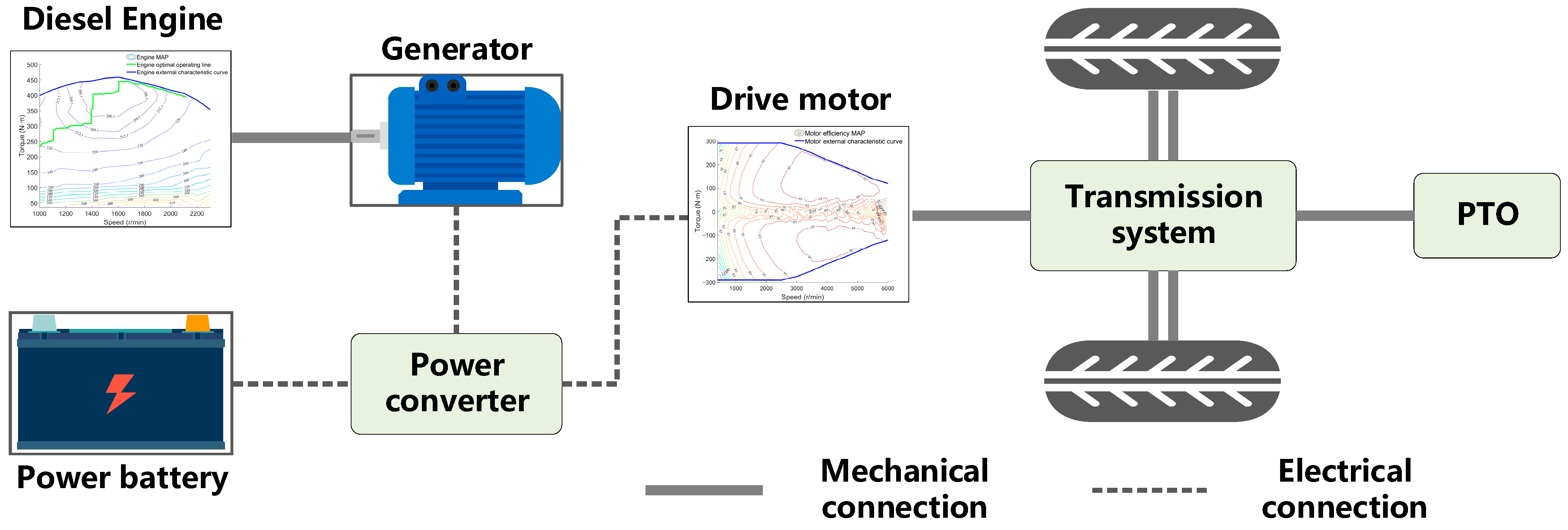
2. Tractor Power System and Main Parameters

The simulation model of the power system topology of the series diesel–electric hybrid tractor built in this paper is shown in Figure 1. This tractor model is powered by a drive motor, with the other major components including a diesel engine, a generator, a power battery, a transmission system, and a power take-off (PTO) device. The power battery provides energy for the drive motor, which drives the tractor through the transmission system while also powering the PTO. When the remaining power of the power battery is insufficient, the engine drives the generator to work and charges the power battery. The main component parameters of the power system of the tractor simulation model are shown in Table 1, including the main performance parameters of the diesel engine and the drive motor, such as power, speed, and torque, as well as the main specification parameters of the power battery.

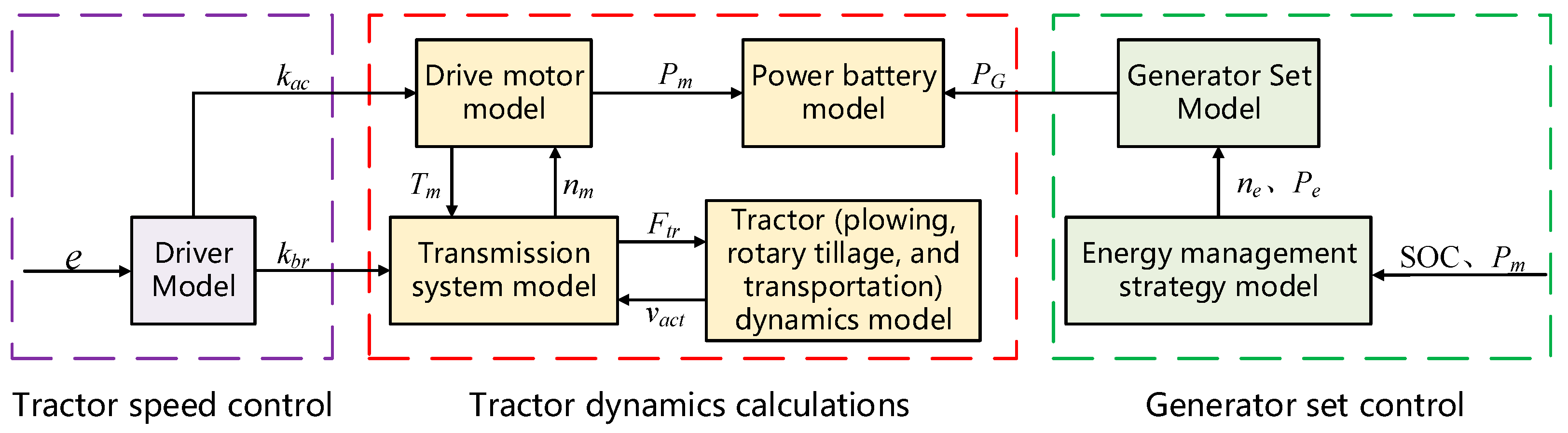
3. Hybrid Tractor Model Construction

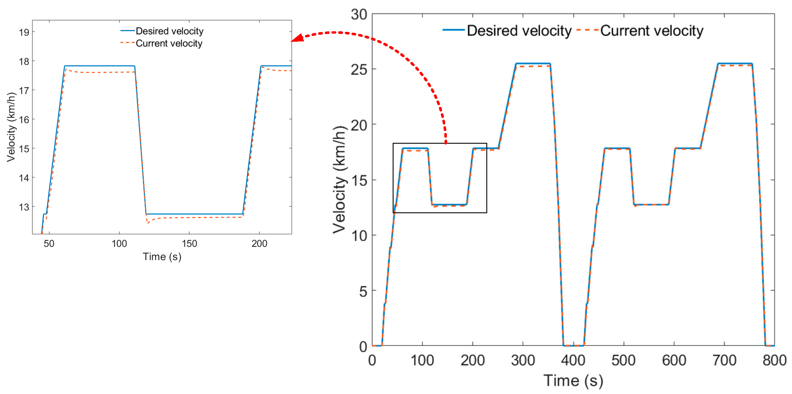
3.1. Tractor Driver Model

Based on the principle of forward modeling, the PI driver model simulates the changes in the accelerator- and brake-pedal positions to control the vehicle speed of the tractor model during driving. The driver model takes the difference between the desired speed and the current speed as the input and the pedal opening as the output. The specific modeling principle is shown in the following equation [39]:
{ k u = k p e + k i e d t k a c = k u , k u ( 0 , 1 ) k b r = k u , k u ( 1 , 0 )
e = v r e f v a c t
where kp is the proportional coefficient, ki is the integral coefficient; e is the difference between the desired velocity of the tractor and the current velocity of the tractor, km/h; ku is the pedal opening, kac is the accelerator-pedal opening, and kbr is the brake-pedal opening; vref is the desired velocity of the tractor, km/h, and vact is the current velocity of the tractor, km/h.

3.2. Generator Set Model

The generator set model is composed of the engine and the generator. In the series hybrid power system structure, the engine does not directly drive the vehicle but charges the power battery by driving the generator, which is relatively independent of the entire power system of the vehicle. The energy management strategy focuses on the research of the vehicle’s fuel economy. Therefore, the numerical modeling method is adopted for the modeling of the generator set. The specific modeling principle is shown in the following formula [40]:
P e = n e T e 9549
P G = P e η G
where Pe is the engine power, kW; ne is the engine speed, r/min; Te is the engine torque, N·m; PG is the generator set power, kW; and ηG is the generator efficiency.
As shown in Figure 2, the engine’s universal characteristics are fitted based on the experimental data of the engine bench test. The figure includes the MAP of the engine’s fuel-consumption rate, the external characteristic curve of the engine, and the optimal operating line (OOL) of the engine.
The calculation of engine fuel consumption is shown in the following formula:
b e = f ( n e , T e )
E = P e b e 3600 ρ f d t
where E is the total fuel consumption of the engine, L; be is the fuel-consumption rate of the engine, g/kWh; and ρf is the density of diesel fuel, g/L.

3.3. Drive Motor Model

As shown in Figure 3, the external characteristic curves of the drive motor and the motor efficiency MAP were fitted using data from drive motor bench tests. Based on the characteristic curve data of the driving motor, numerical modeling of the driving motor is carried out using data interpolation. The power output of the driving motor is controlled by the pedal opening signal output by the driver model. The specific modeling principle is shown in the following formula [41]:
T m _ max = f ( n m )
T m = k a c T m _ max
η m = f ( n m , T m )
P m = n m T m 9549 η m
where nm is the drive motor speed, r/min; Tm is the drive motor torque, N·m; Tm_max is the maximum torque at the current drive motor speed; kac is the accelerator-pedal opening; ηm is the drive motor efficiency; and Pm is the drive motor power, kW.

3.4. Transmission System Model

In the series hybrid power system structure, the driving motor provides power to the tractor and then transmits the power to the driving wheels and PTO through the transmission system. The specific modeling process is shown in the following equation:
F t r = T m i g i 0 η T R w F b r
F b r = k b r F b r _ max
n m = v a c t i g i 0 0.377 R w
where Ftr is the forward traction force acting on the tractor through the transmission system by the drive motor torque, N; ig is the gear ratio of the transmission; i0 is the gear ratio of the final drive; ηT is the efficiency of the transmission system; Rw is the radius of the drive wheel, m; Fbr is the braking force of the brake, N; and Fbr_max is the maximum braking force of the brake, N.

3.5. Power Battery Model

In the research on energy management strategies, the modeling of the power battery mainly considers the changes in battery power and battery SOC. Therefore, the Rint model is adopted to model the power battery. The specific model is shown in the following equation [42]:
SOC = U o c U o c 2 4 R int P B 2 Q B R int
P B = { ( P m + P e ) η B , ( P m + P e ) < 0 ( P m + P e ) η B , ( P m + P e ) > 0
where Uoc is the open-circuit voltage of the power battery, V; Rint is the internal resistance of the power battery, Ω; PB is the battery power, kW; QB is the rated capacity of the battery, A·h; and ηB is the charge and discharge efficiency of the power battery. When (Pm + Pe) is less than zero, the power battery is charging; when (Pm + Pe) is greater than zero, the power battery is discharging.

3.6. Tractor Plowing Condition Dynamics Model

When a tractor performs plowing operations, the driving resistance it experiences is mainly determined by the rolling resistance and the plowing resistance. The relationship of the balance of driving resistances for the tractor under plowing conditions is given by the following equation:
F t = F t r ( F L + F f )
F L = Z b h k
F f = m g f cos α
v a c t = F t 3.6 m d t
where Ft is the driving force, N; FL is the plowing resistance, N; Ff is the rolling resistance, N; Z is the number of plowshares; b is the width of a single plowshare, cm; h is the plowing depth, cm; k is the specific resistance of the soil, N/cm2; m is the operating mass of the tractor, kg; g is the acceleration of gravity, m/s2; f is the rolling resistance coefficient; and α is the slope angle, (°).

3.7. Tractor Rotary Tillage Condition Dynamics Model

When a tractor performs rotary tillage operations, its load power is mainly determined by the tractor’s driving power and the rotary tiller’s power. In the research on energy management strategies, the theoretical calculation for rotary tillage conditions is overly complex. Therefore, this article uses empirical formulas for calculation, and the power balance is shown in the following formula [43]:
P m = P d r i v e + P r
P d r i v e = v a c t ( F f + F i ) 3600 η T
F i = m g sin α
P r = 3.6 k B h v a c t η r
where Pdrive is the tractor’s driving power, kW; Fi is the slope resistance, N; Pr is the power of the rotary tiller, kW; B is the width of the rotary tillage area, m; and ηr is the transmission efficiency of the rotary tiller unit.

3.8. Tractor Transportation Condition Dynamics Model

For the transportation operations of the tractor, the acceleration resistance and the air resistance need to be considered. The specific relationship of the balance of driving resistances is given by the following equation:
F t = F t r ( F f + F i + F a c + F a r )
F a c = m δ a
F a r = C D A v a c t 2 21.15
where Fac is the acceleration resistance, N; Far is the air resistance, N; δ is the tractor mass-conversion coefficient; a is the tractor acceleration, m/s2; CD is the wind-resistance coefficient of the tractor; and A is the windward area of the tractor, m2.

3.9. Tractor Simulation Model

The specific structure of the tractor simulation model is shown in Figure 4, which can be divided into three parts according to the function of the model: the generator set control, the tractor speed control, and the tractor dynamics calculation. The generator set control includes the generator set model and the energy management strategy model. The speed control includes the driver model. The tractor dynamics calculations include the transmission system model, driving motor model, dynamics models for various working conditions of the tractor, and power battery model. The main simulation parameters of the tractor under different working conditions are shown in Table 2. The specific simulation principle of the tractor model is that the energy management strategy model controls the start/stop and output power PG of the generator set based on the current battery SOC and driving motor power Pm to achieve generator set control. The driver model outputs the accelerator-pedal opening kac and the brake-pedal opening kbr based on the difference e between the current speed and the desired speed to achieve speed control. The driving motor model, transmission system model, and tractor dynamics model calculate the current driving motor power Pm based on the pedal opening and, finally, calculate the current working state of the power battery through the driving motor power Pm and generator set power PG to complete the relevant calculations of tractor dynamics.

4. Energy Management Strategy Design

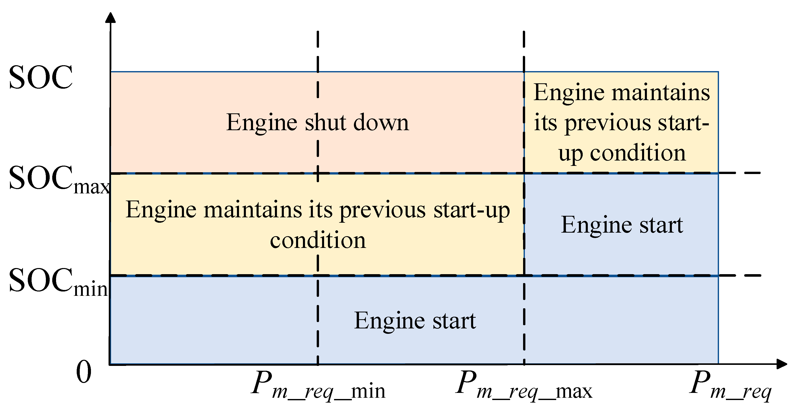
4.1. Energy Management Strategy Based on Power Following

The energy management strategy based on power following is a rule-based energy management strategy, which is widely used and often serves as a comparison strategy to evaluate the control effect of the energy management strategy. In the structure of a series hybrid power system, the PF strategy controls the operation state of the engine based on the SOC of the power battery and the power demand of the driving motor. This paper improves the PF strategy, making it select the engine working point from the OOL curve in Figure 2, ensuring that the engine works in the best state and further reducing fuel consumption. In previous research, the basic principles of the PF strategy have been described in detail. The control principle of the PF strategy is illustrated in Figure 5. For a specific process, please refer to reference [34], which will not be repeated here.

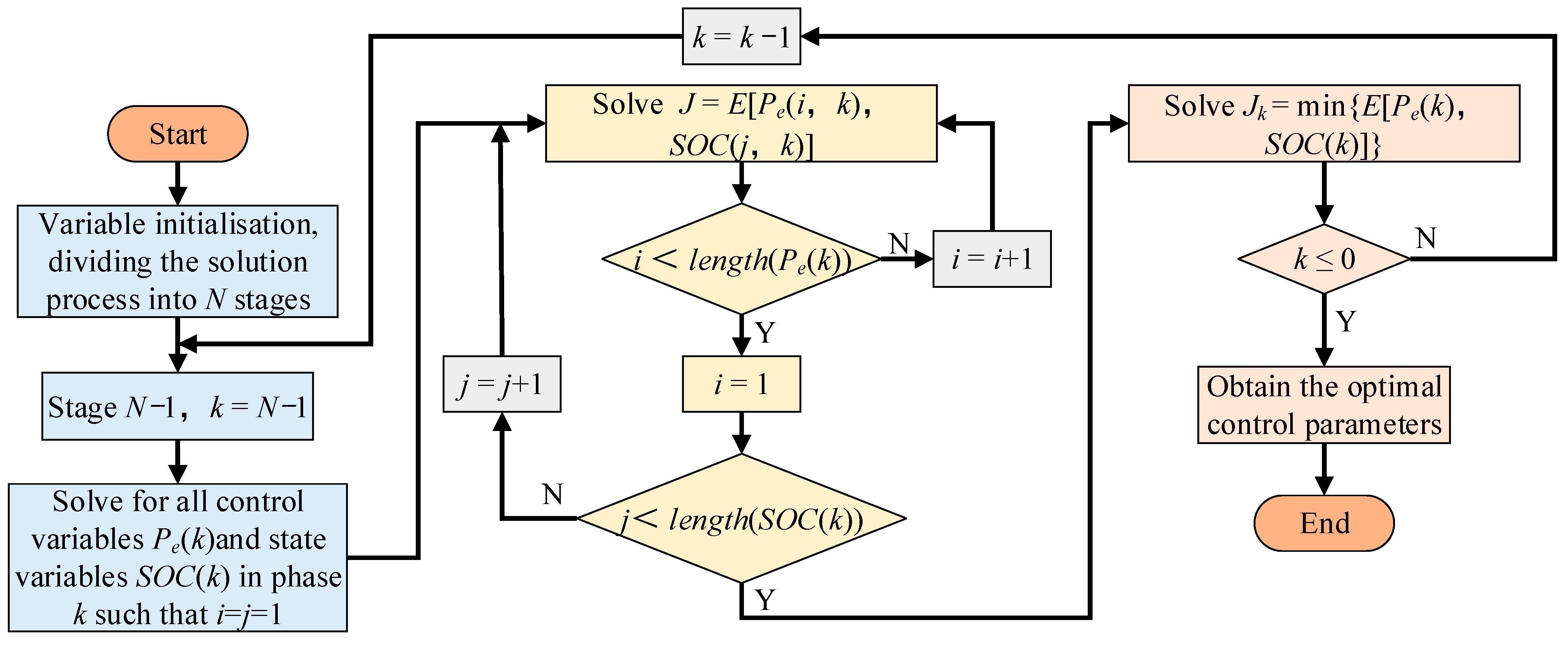
4.2. Energy Management Strategy Based on Dynamic Programming

4.2.1. Dynamic Programming Algorithm Model Building

Dynamic programming is a global optimization algorithm whose basic principle is to divide the overall optimization process into multiple single-step optimization stages. By defining appropriate control variables and state variables, it utilizes a backward solution to obtain the optimal solution of the objective function, thus achieving the optimal control parameters [44].
In the structure of a series hybrid power system, the change trend of the SOC can reflect the operating state of the tractor, while the change of the SOC is mainly affected by the engine power. Therefore, SOC is selected as the state variable, engine power as the control variable, and tractor fuel consumption as the objective function to build a dynamic programming-based energy management strategy model.
With an interval of 1 s, the entire tractor simulation condition is decomposed into N stages, discretizing the control variables and state variables, as shown in the following equation:
{ x ( k ) = [ SOC ( k ) ] T SOC ( k ) { SOC 1 ,   SOC 2 ,   ,   SOC N } u ( k ) = [ P e ( k ) ] T u N ( k ) { u N 1 ,   u N 2 ,   ,   u N M }
where N is the dimension of the discrete space and M is the number of discrete points.
According to Equations (6) and (14), the state transition equation and optimization objective function of the battery SOC are as follows:
SOC ( k + 1 ) = SOC ( k ) + U o c ( t ) U o c 2 ( t ) 4 R int ( t ) P B ( t ) 2 Q B R int ( t )
J = min k = 0 N 1 E [ SOC ( k ) ,   P e ( k ) ]
To ensure that the tractor model can perform reasonable simulation calculations during the optimization process, the following constraints are added:
{ SOC min SOC ( k ) SOC max P B _ min P B ( k ) P B _ max P e _ min P e ( k ) P e _ max n e _ min n e ( k ) n e _ max T e _ min T e ( k ) T e _ max
where PB_min and PB_max are the minimum and maximum power of the power battery during operation; and Pe_min, Pe_max, ne_min, ne_max, Te_min, and Te_max are the minimum and maximum power, minimum and maximum speed, and minimum and maximum torque of the engine during operation, respectively.

4.2.2. The Solution Process of Dynamic Programming Algorithm

Based on the current working condition of the tractor, the DP strategy uses the dynamic programming algorithm to solve for the minimum objective function, thereby obtaining the optimal control parameters. In previous research, the solution process of the DP strategy has been described in detail. The flowchart of the dynamic programming algorithm is shown in Figure 6 [45]. For a specific process, please refer to reference [34], which will not be repeated here. To further optimize the control effect of the DP strategy, the DP strategy will also select engine control parameters from the fitted OOL curve in Figure 2, enabling the tractor to achieve better fuel economy.

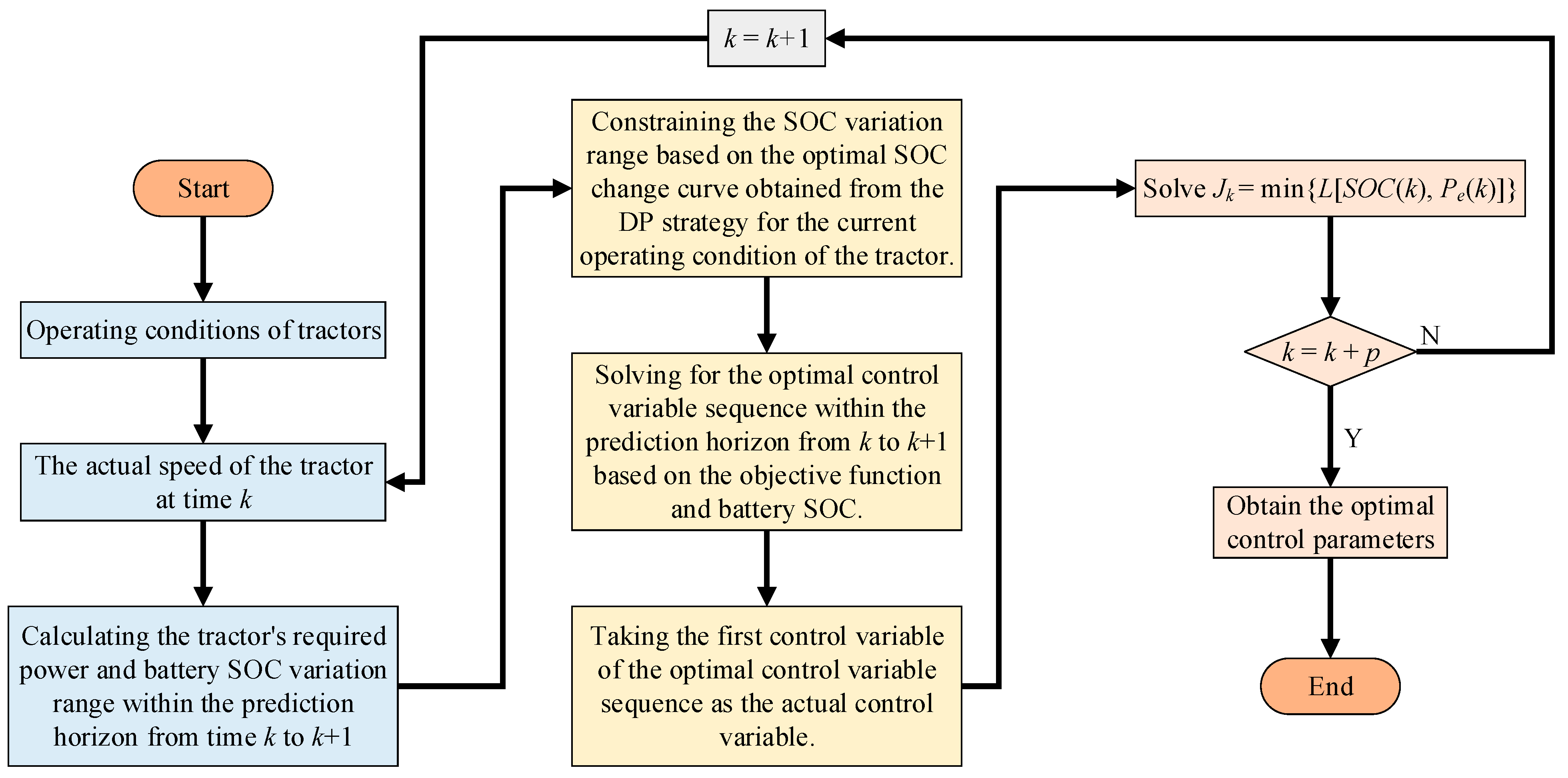
4.3. Energy Management Strategy Based on Model Predictive Control Solved by Dynamic Programming

4.3.1. Model Predictive Control-Based Energy Management Strategy Model

The research focus of the energy management strategy for series hybrid tractors lies in how to reasonably allocate the power balance between the power battery and the engine based on the working conditions, thereby improving the fuel economy of the tractor. The energy management strategy based on model predictive control divides the energy management problem under the entire working condition into local optimal problems within a limited prediction horizon. Through rolling optimization, the control effect of approximate global optimization is achieved through local optimization [46].
The tractor simulation model remains unchanged. Therefore, the MPC strategy selects the same state variables and control variables as the DP strategy. Specifically, the state of charge (SOC) of the power battery is chosen as the state variable, the engine power as the control variable, and the optimization objective function is the fuel consumption of the tractor. However, the optimization objective is transformed from the global optimal problem under the tractor’s working conditions to a local optimal problem within the prediction horizon. The tractor model takes the first control variable of the optimal control sequence at a certain moment as the model control parameter, making the operation status of the tractor model change. It then re-predicts the operation status of the tractor model at the next moment and obtains the corresponding optimal control sequence in the new prediction horizon. Repeat this process until the optimal control parameters under the entire working condition are obtained. The optimization objective function and the constraints of the MPC strategy are as follows:
J k = min t = k k + p L [ x ( t ) ,   u ( t ) ]
{ x min ( t ) x ( t ) x max ( t ) u min ( t ) u ( t ) u max ( t ) k t k + p
where L is the instantaneous cost function at time t, and p is the length of the prediction horizon.
By substituting the tractor model parameters into Equations (31) and (32), the optimized objective function and constraint conditions within the prediction horizon at time k can be obtained as follows:
J k = min t = k k + p L [ SOC ( k ) ,   P e ( k ) ]
{ SOC min SOC ( k ) SOC max P B _ min P B ( k ) P B _ max P e _ min P e ( k ) P e _ max n e _ min n e ( k ) n e _ max T e _ min T e ( k ) T e _ max

4.3.2. The Solution Process of Model Predictive Control

To ensure that the minimum objective function, namely the lowest fuel consumption of the tractor, is obtained within the prediction horizon at any given time, the MPC strategy constrains the output of the control variable engine power during the solution process. This results in a too-fast decrease in the SOC of the battery, until the SOC drops to its lower limit. Therefore, it is necessary to constrain the change in the state variable, the SOC of the battery, at every moment during the MPC strategy solution process. In Section 4.2, the SOC variation curve of the tractor obtained through the DP strategy can be regarded as the globally optimal SOC variation trajectory under the current working conditions of the tractor. Therefore, the SOC variation curve of the DP strategy is used as the SOC constraint condition for solving the MPC strategy [47].
The solution process of the energy management strategy based on DP-MPC is shown in Figure 7. For each prediction horizon within the time domain from k + 1 to k + p, within the constraint range of the SOC variation trajectory of the DP strategy, the battery SOC is discretized to solve for the optimal control variables corresponding to all state variables and the optimal objective function at the end of each prediction horizon. The specific principle is shown in the following equation [48]:
J k * [ SOC ( k ) ] = min u ( k ) { L [ SOC ( k ) ,   P e ( k ) ] + J k + 1 * [ SOC ( k + 1 ) ] }
where J k * is the optimal objective function when reaching the end of the prediction horizon at k + p under the conditions of the current state variable SOC(k) at time k. The corresponding control variable u*(k) at this time is the optimal control variable at time k.

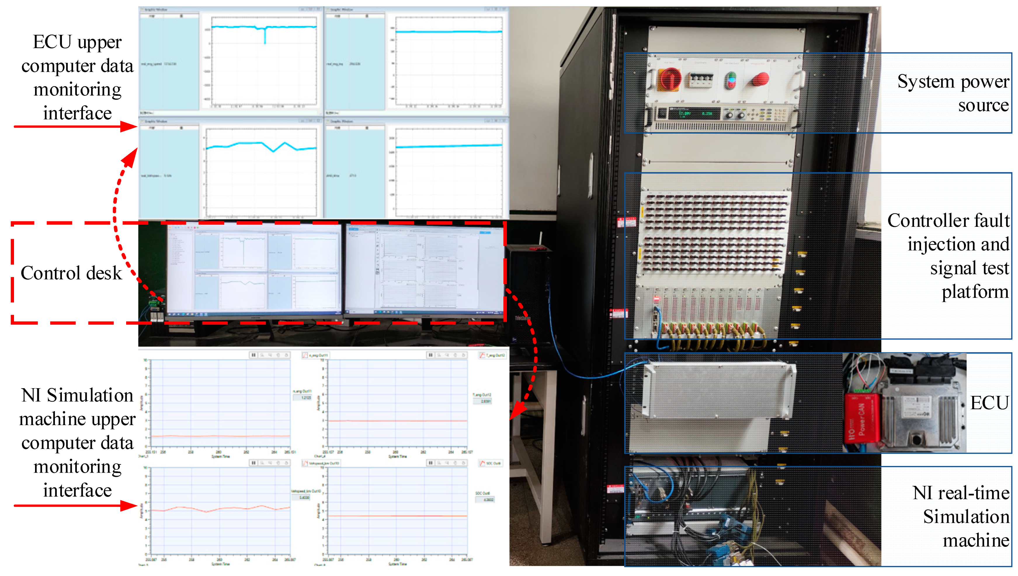
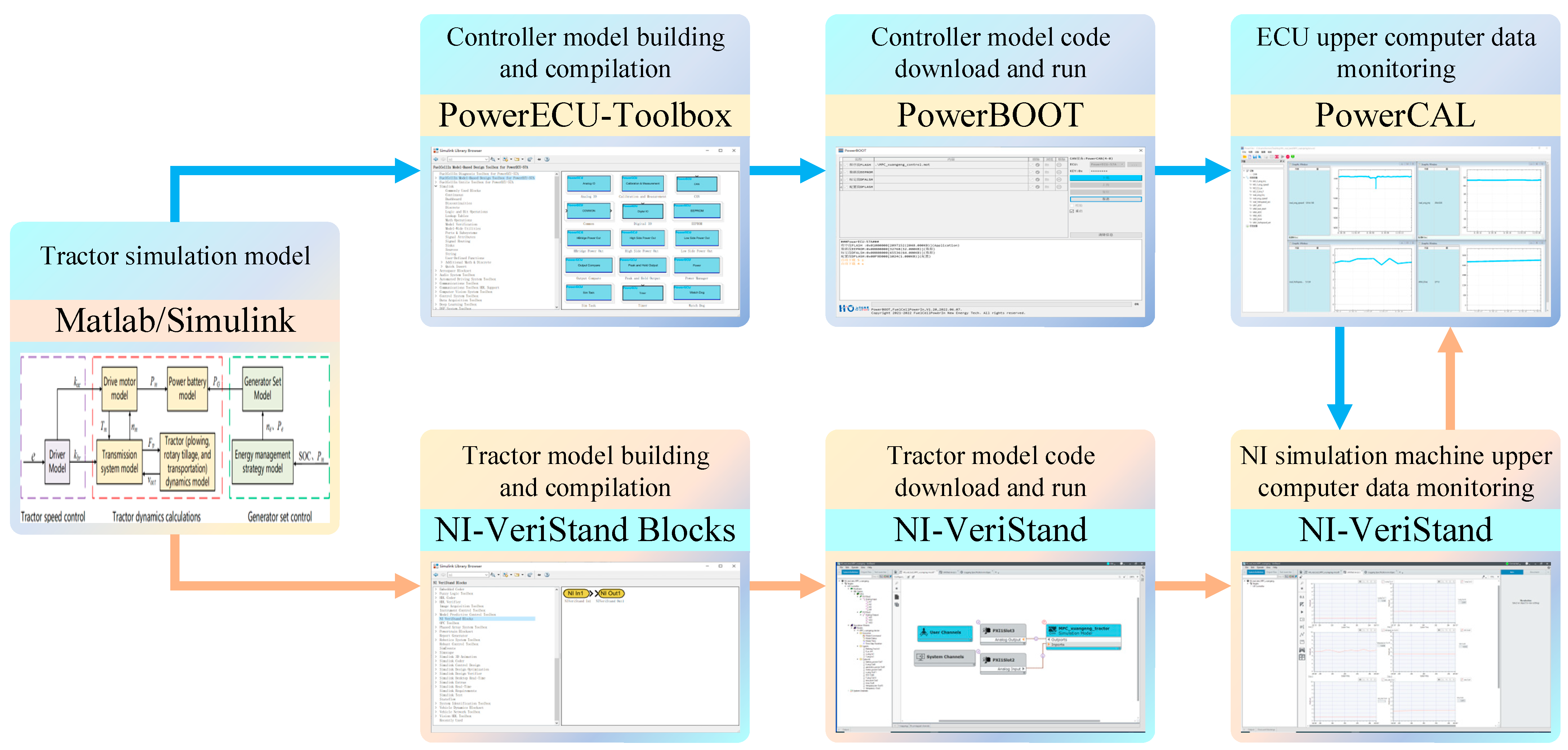
5. Analysis and Discussion of Hardware-in-the-Loop Test Results

5.1. Hardware-in-the-Loop Test Platform Setup

The HIL test platform built in this article is shown in Figure 8. The main hardware includes the HIL test cabinet and the vehicle controller. The test process of HIL is shown in Figure 9. Specifically, the tractor simulation model built in Figure 4 is divided into a controller model and a tractor model. The controller model consists of two parts, namely the generator set control and the tractor speed control. The tractor model comprises tractor dynamics calculations. The HIL test cabinet produced by National Instruments and the vehicle controller PowerECU-57A produced by Shandong Hydrogen Exploration New Energy Technology Co., Ltd. of China (Jinan, China) were used to add corresponding I/O modules for the controller model and the tractor model through the controller and the corresponding Simulink plug-ins of the NI real-time simulator, PowerECU-Toolbox and NI-VeriStand Blocks, add the corresponding I/O modules for the controller model and tractor model. The models are then compiled, and C code is generated using the target language compiler (TLC) files corresponding to the controller and the NI real-time simulation machine, as well as the Matlab/RTW code generator. Using software tools such as PowerBOOT V1.10, the compiled code files of the model are downloaded to the controller and the NI real-time simulation machine. The card configuration for the controller and the NI real-time simulation machine is conducted in NI-VeriStand. Analog quantity communication is used between the controller and the NI real-time simulation machine, and the HIL test process is monitored in real-time through PowerCAL V1.32 and NI-VeriStand 2020.

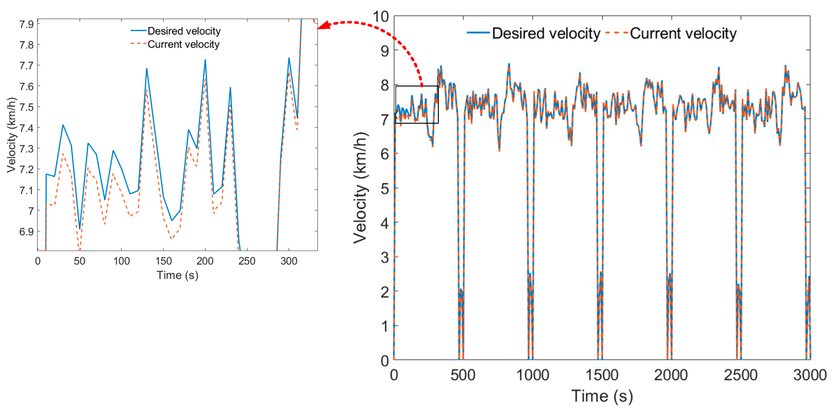
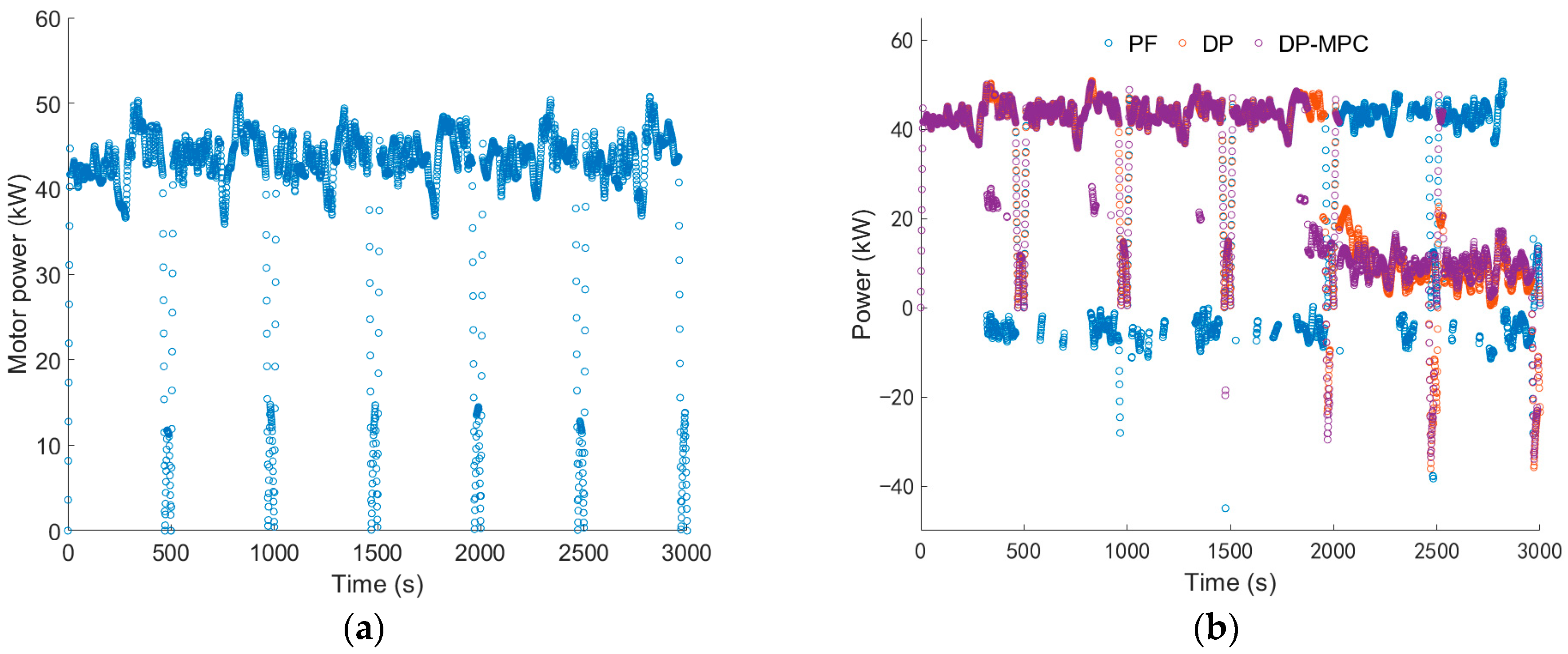
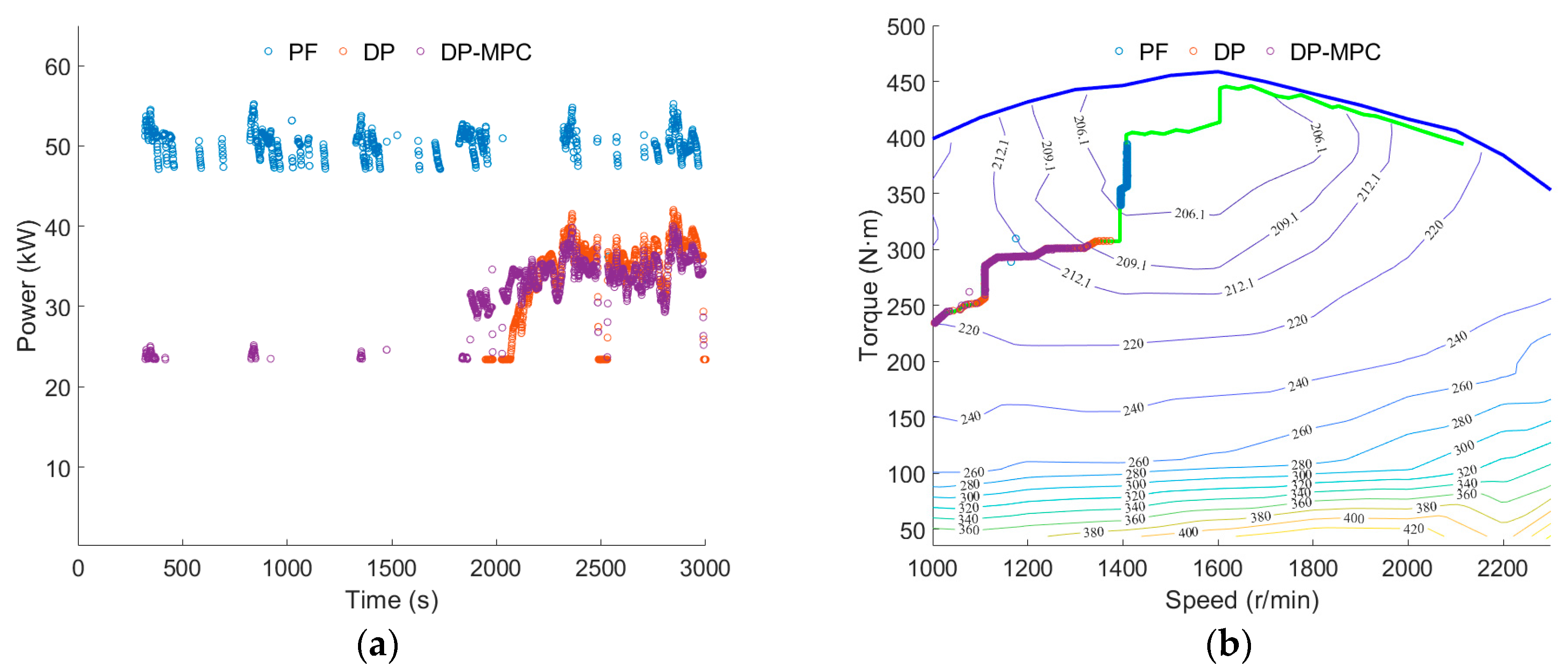
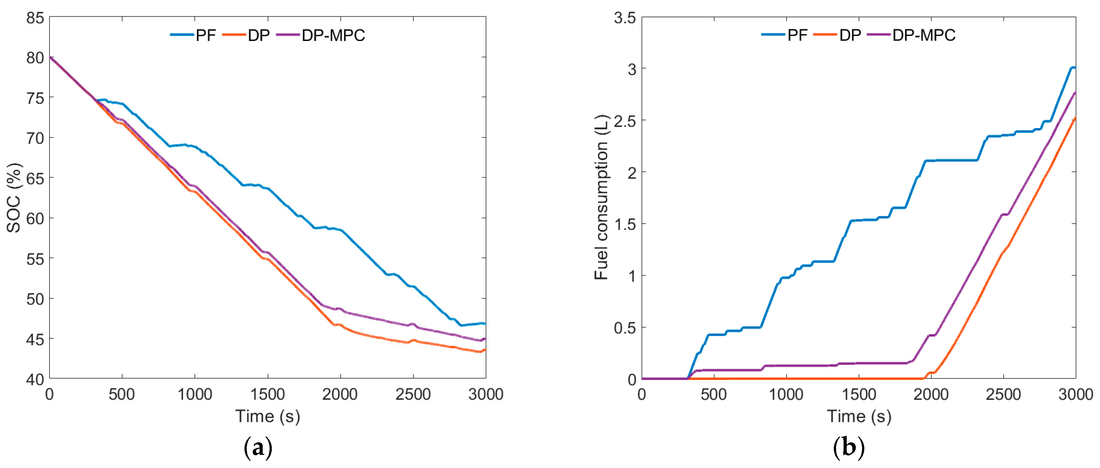
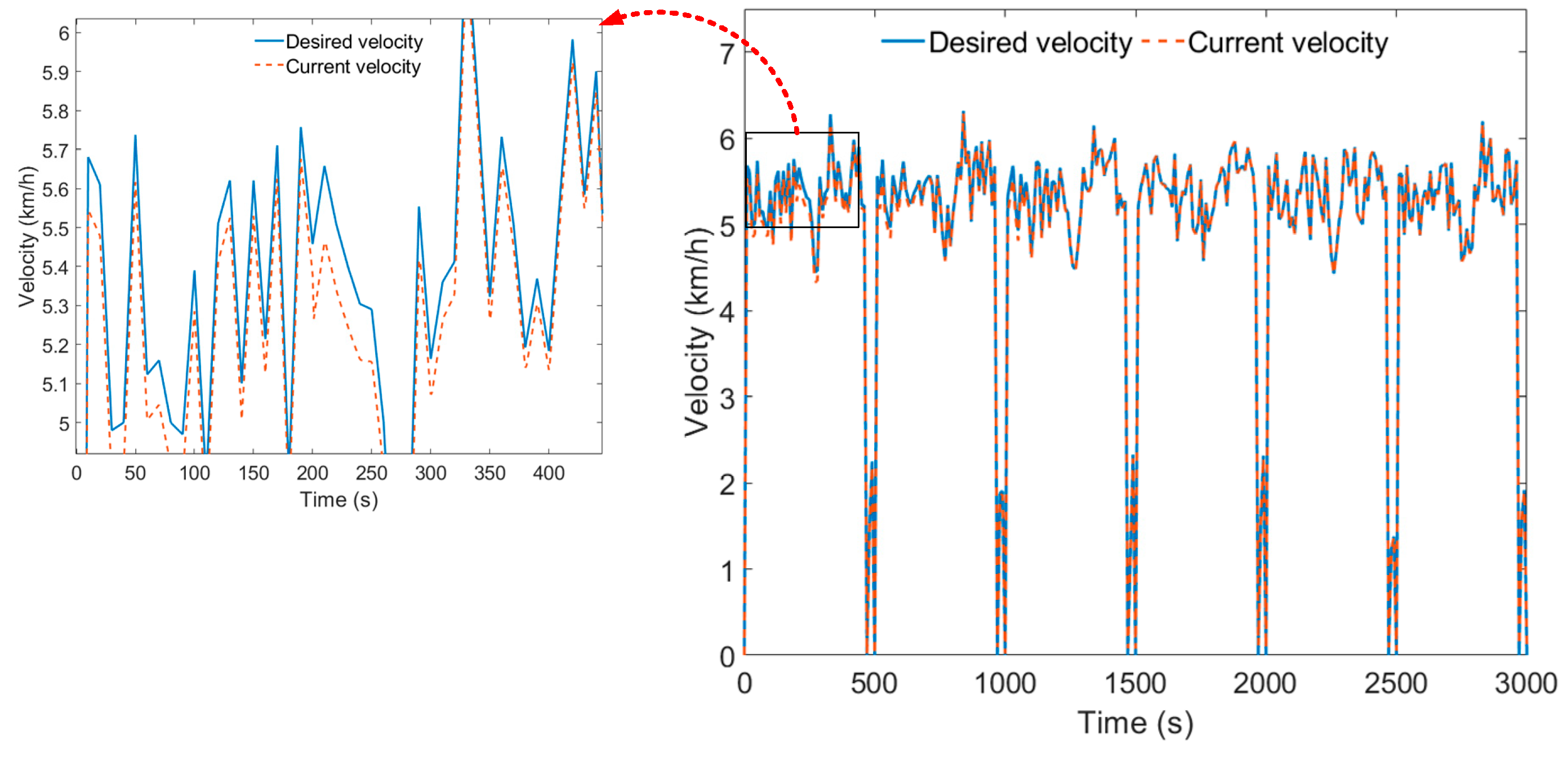
5.2. Result Analysis

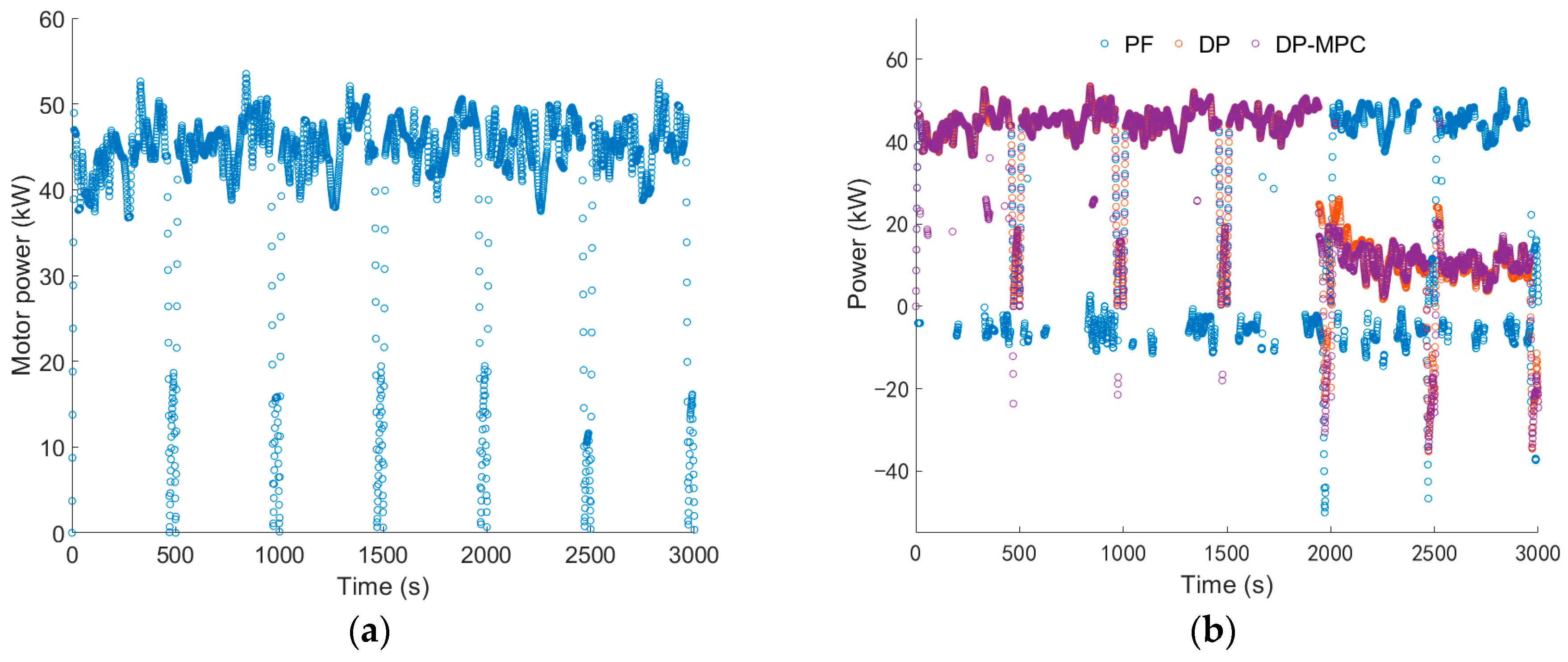
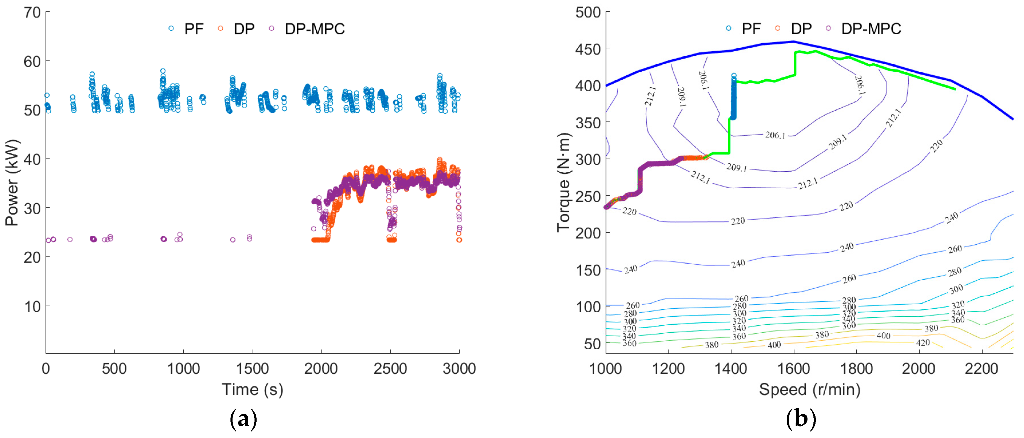
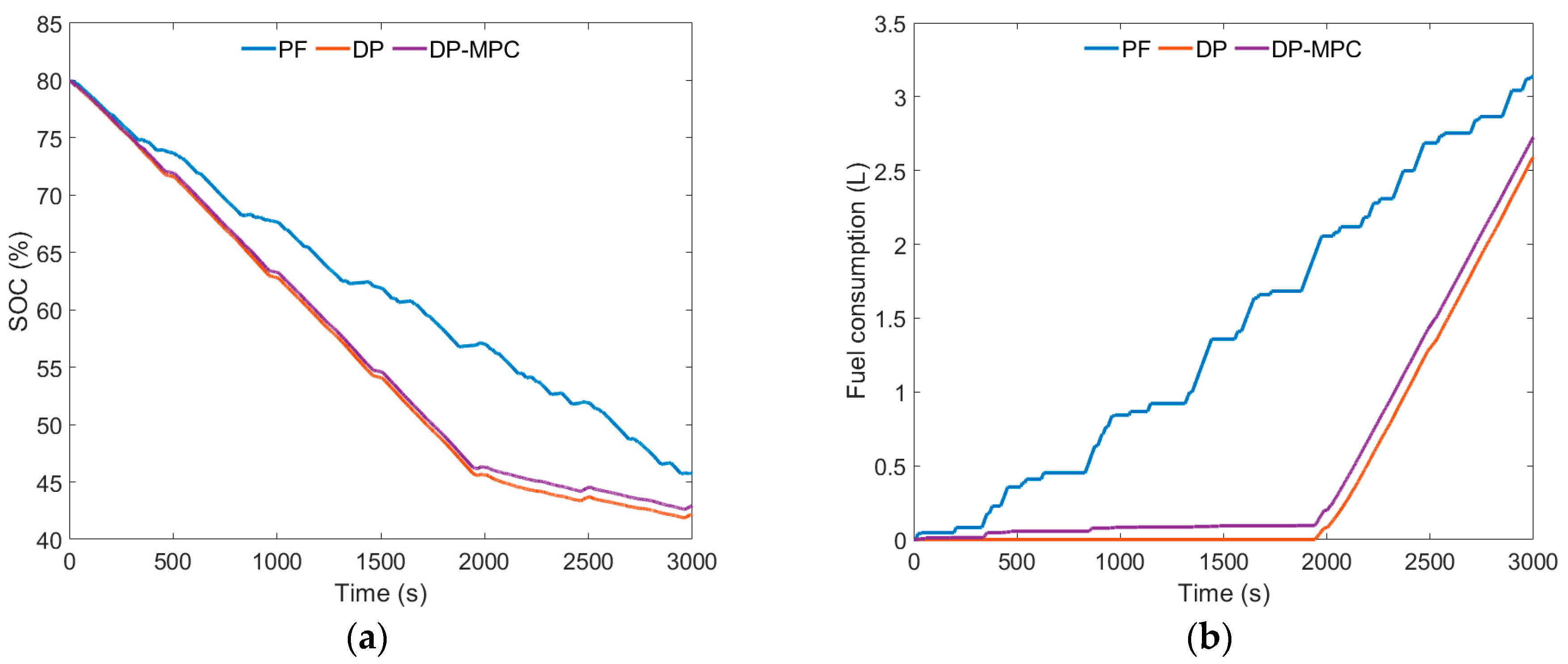
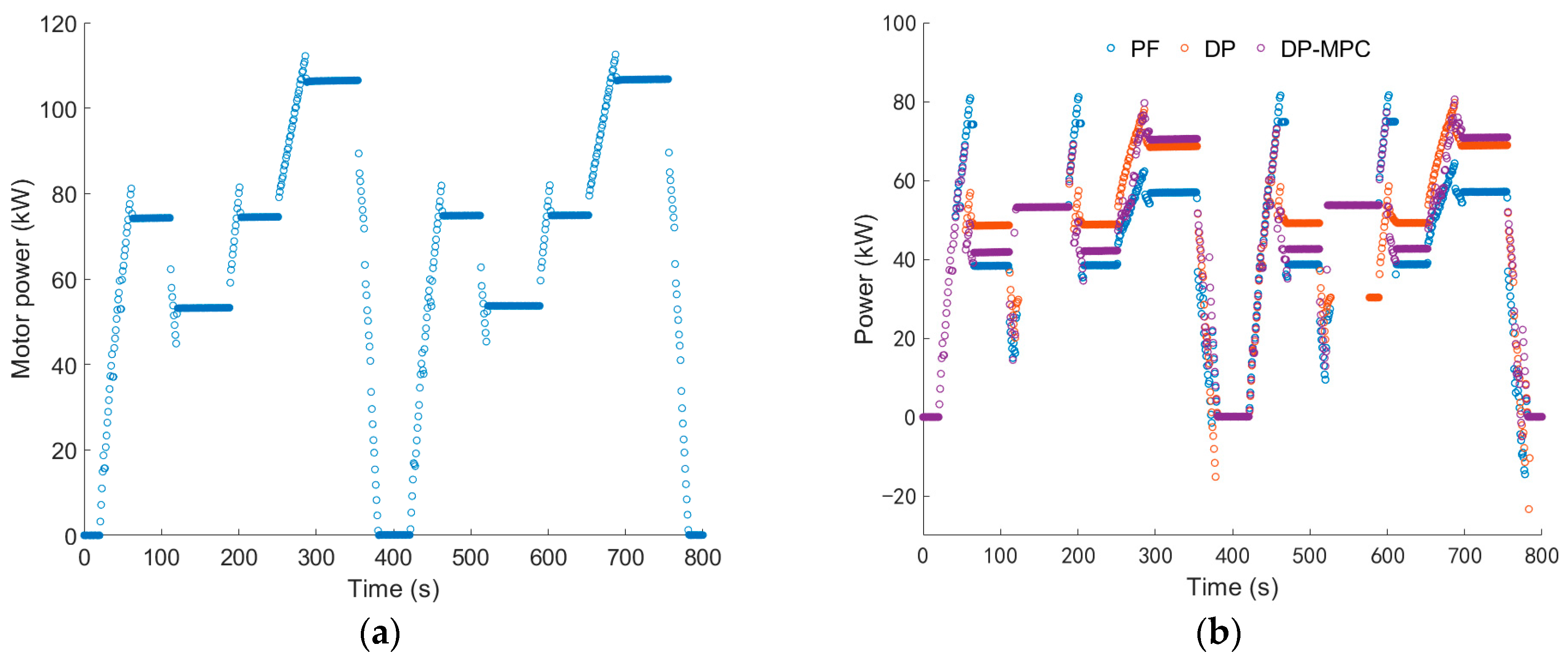
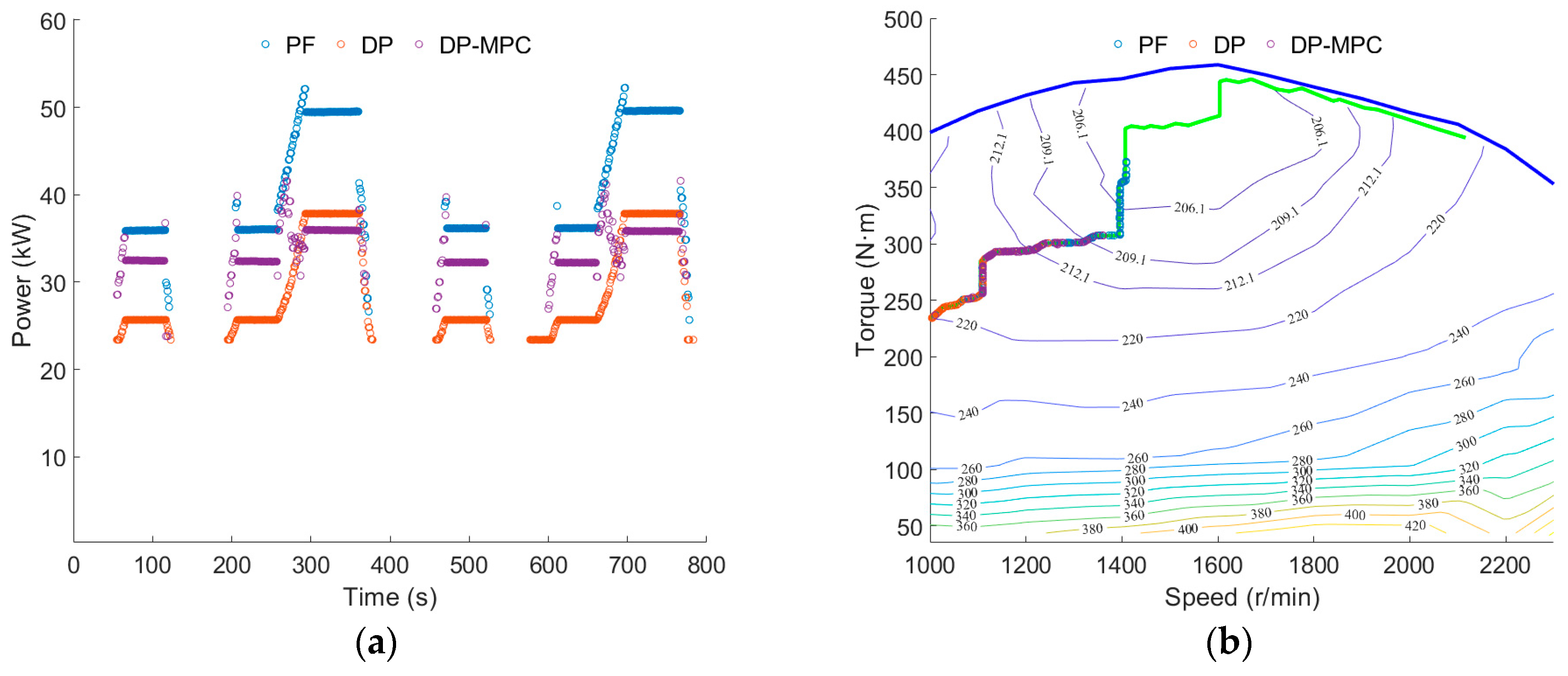
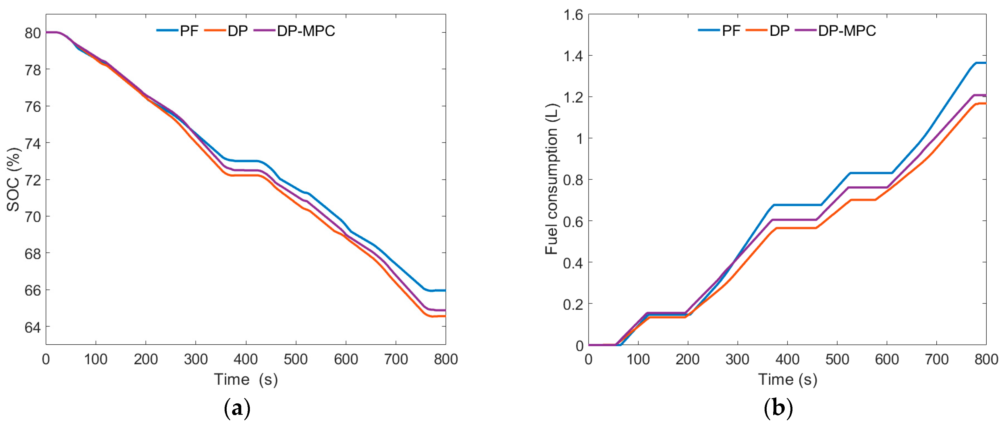
5.2.1. Plowing Condition

The plowing working condition consists of six working cycles with the same duration, totaling 3000 s, as shown in Figure 10. Based on the desired velocity following effect of the hardware-in-the-loop test under the plowing working condition, the controller and the NI real-time simulation machine can accurately exchange data, and the test model can follow the desired velocity very well. The error between the current velocity and the desired velocity remains within −0.15 to 0.29 km/h.
The driving motor power of the tractor under the plowing working condition, the battery power under three control strategies, and the changes in the engine operating state are shown in Figure 11 and Figure 12. In a series hybrid power system, all the power of the tractor comes from the driving motor, so the power change of the driving motor can reflect the load change of the tractor under the current working condition. As can be seen from Figure 11 and Figure 12, under the plowing working condition, the power of the driving motor is concentrated between 35 and 50 kW, with a peak power of approximately 50.86 kW. The total power consumption of the driving motor under the plowing working condition is approximately 33.97 kWh.
Under the PF strategy, during each plowing cycle, the battery power drops below zero, indicating that the engine starts to recharge the battery in every plowing cycle, with the engine power concentrated between 47 and 54 kW, resulting in frequent engine start-stop operations.
Under the DP strategy, around 1948 s, the battery power begins to decline, and around 1965 s, the battery power starts to be less than zero. The engine power is concentrated between 23 and 42 kW, and the engine’s working time is relatively concentrated, without frequent start–stop operations.
Under the DP-MPC strategy, in the first three working cycles, the battery power experienced a short-term drop, but it did not fall below zero. At around 1875 s, the battery power began to continuously decrease, and around 1964 s, the battery power started to be less than zero. The engine power was concentrated between 23 and 40 kW, and the engine’s working time was relatively concentrated after approximately 1875 s.
Under all three control strategies, the engine was operating within the OOL curve range.
As shown in Figure 13a, the remaining SOC under the PF strategy is approximately 46.79%, the remaining SOC under the DP strategy is approximately 43.65%, and the remaining SOC under the DP-MPC strategy is approximately 44.94%. Compared to the PF strategy, the DP-MPC strategy consumes approximately 3.95% more battery SOC. Compared to the DP strategy, the DP-MPC strategy reduces battery SOC consumption by approximately 2.87%.
As shown in Figure 13b, the fuel consumption of the PF strategy is 3.01 L, the fuel consumption of the DP strategy is 2.53 L, and the fuel consumption of the DP-MPC strategy is 2.77 L. Compared to the PF strategy, the fuel consumption of the DP-MPC strategy has decreased by approximately 7.97%, achieving approximately 91.34% of the fuel-saving performance of the DP strategy.

5.2.2. Rotary Tillage Condition

The rotary tillage working condition consists of six working cycles with the same duration, totaling 3000 s, as shown in Figure 14. Based on the expected vehicle speed following effect of the hardware-in-the-loop test under the rotary tillage working condition, the test model can effectively follow the desired vehicle speed, with the error between the current vehicle speed and the expected vehicle speed maintained within −0.17 to 0.36 km/h.
The driving motor power of the tractor under rotary tillage conditions, the battery power under three control strategies, and the changes in engine operating state are shown in Figure 15 and Figure 16. As can be seen from Figure 15 and Figure 16, under rotary tillage conditions, the driving motor power is concentrated between 40 and 50 kW, the peak power is about 53.51 kW, and the total power consumption of the driving motor under rotary tillage conditions is about 35.16 kWh.
Under the PF strategy, similar to the plowing condition, during each rotary tillage cycle, the battery power will drop below zero, resulting in frequent engine start–stop operations, and the engine power is concentrated between 49 and 58 kW.
Under the DP strategy, at around 1943 s, the battery power begins to decline, and at around 1967 s, the battery power starts to fall below zero. The engine power is concentrated between 23 and 39 kW, and the engine’s working hours are relatively concentrated without frequent start–stop operations.
Under the DP-MPC strategy, during the first three working cycles, the battery experienced short-term power reduction and a power level below zero. At around 1942 s, the battery power began to continuously decline, and around 1970 s, the battery power fell below zero. The engine power was concentrated between 23 and 38 kW, and the engine’s working hours were relatively concentrated after approximately 1942 s.
Under all three control strategies, the engine operated within the OOL curve range.
As can be seen from Figure 17a, the remaining SOC of the PF strategy is approximately 45.73%, the remaining SOC of the DP strategy is approximately 42.19%, and the remaining SOC of the DP-MPC strategy is approximately 42.93%. Compared to the PF strategy, the DP-MPC strategy consumed approximately 6.12% more battery SOC. In contrast to the DP strategy, the DP-MPC strategy reduced battery SOC consumption by approximately 1.72%.
As shown in Figure 17b, the fuel consumption of the PF strategy is 3.14 L, the fuel consumption of the DP strategy is 2.59 L, and the fuel consumption of the DP-MPC strategy is 2.73 L. Compared to the PF strategy, the fuel consumption of the DP-MPC strategy decreased by approximately 13.06%, achieving approximately 94.87% of the fuel-saving performance of the DP strategy.

5.2.3. Transportation Condition

The transportation condition refers to the EUDC_Man driving cycle, and based on the tractor power system parameters, the maximum speed is modified to 25.5 km/h. The transportation condition consists of two cycles with the same duration, totaling 800 s, as shown in Figure 18. According to the desired speed following effect of the hardware-in-the-loop test under the transportation condition, the test model can follow the expected speed very well, and the error between the current speed and the expected speed remains within −0.50 to 0.48 km/h.
The driving motor power of the tractor under transportation conditions, the battery power under three control strategies, and the change in engine operating status are shown in Figure 19 and Figure 20. As can be seen from Figure 19 and Figure 20, under transportation conditions, the driving motor power is concentrated between 50 and 105 kW, with a peak power of approximately 112.55 kW. The total power consumption of the driving motor under transportation conditions is approximately 14.56 kWh.
Under transportation conditions, the battery power trends of the three control strategies are basically the same. But, the DP strategy experiences short-term power of less than zero during each transportation cycle, while the PF strategy and DP-MPC strategy only exhibit short-term battery power of less than zero after approximately 770 s. The changes in engine power are also basically consistent. During the 270 s to 290 s and 670 s to 690 s of the transportation cycle, the engine power of the PF strategy and the DP strategy will increase significantly, while the change in engine power of the DP-MPC strategy is relatively small. Under the three control strategies, the engine has been operating within the OOL curve range.
As shown in Figure 21a, the remaining SOC under the PF strategy is approximately 65.96%, the remaining SOC under the DP strategy is approximately 64.56%, and the remaining SOC under the DP-MPC strategy is approximately 64.88%. Compared to the PF strategy, the DP-MPC strategy consumes approximately 1.64% more battery SOC. In contrast to the DP strategy, the DP-MPC strategy reduces the battery SOC consumption by approximately 0.49%.
As shown in Figure 21b, the fuel consumption under the PF strategy is 1.36 L; under the DP strategy, it is 1.17 L; and under the DP-MPC strategy, it is 1.21 L. Compared to the PF strategy, the fuel consumption of the DP-MPC strategy has decreased by approximately 11.03%, achieving approximately 96.69% of the fuel-saving performance of the DP strategy.

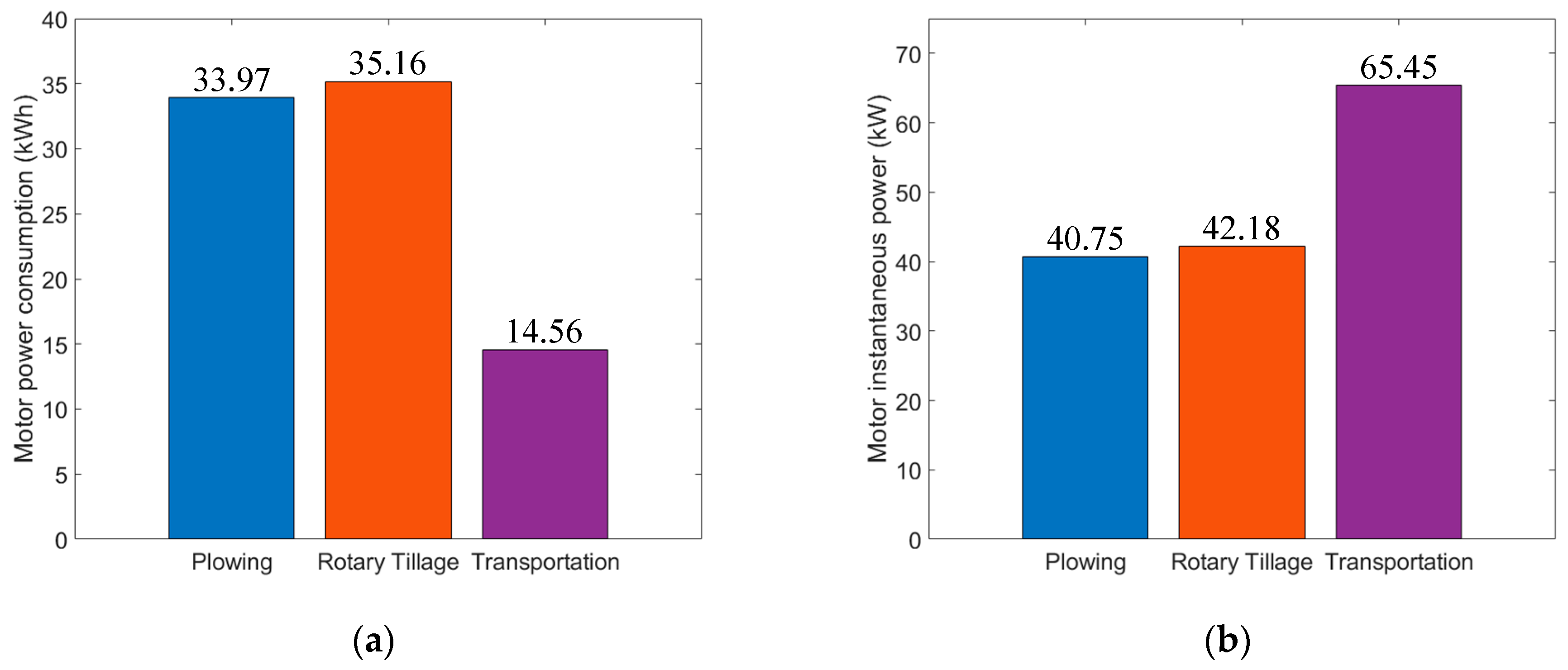
5.3. Comparative Discussion

The fuel consumption and remaining SOC of the three control strategies under different working conditions are shown in Figure 22. Under plowing, rotary tillage, and transportation conditions, compared to the PF strategy, the fuel consumption of the DP strategy is reduced by approximately 15.95%, 17.52%, and 13.97%, respectively. The fuel consumption of the DP-MPC strategy is reduced by approximately 7.97%, 13.06%, and 11.03%, respectively. The DP-MPC strategy achieves approximately 91.34%, 94.87%, and 96.69% of the fuel-saving performance of the DP strategy. Compared to the PF strategy, the DP-MPC strategy consumes approximately 3.95%, 6.12%, and 1.64% more battery SOC under plowing, rotary tillage, and transportation conditions, respectively. In comparison to the DP strategy, the DP-MPC strategy consumes approximately 2.87%, 1.72%, and 0.49% less battery SOC under plowing, rotary tillage, and transportation conditions, respectively.
The total power consumption and average instantaneous power of the drive motor under different working conditions are shown in Figure 23. As mentioned earlier, in a series hybrid power system, the load change of the drive motor can reflect the overall load of the tractor under the current working condition. As can be seen from Figure 23, the order of total power consumption of the tractor under the three working conditions is transportation < plowing < rotary tillage, and the order of average instantaneous load power of the tractor is plowing < rotary tillage < transportation.
Based on the data results in Figure 22 and Figure 23, it can be seen that different driving conditions have a significant impact on the fuel-saving performance of the three control strategies. Compared to the PF strategy, the DP strategy achieves the best fuel-saving effect under rotary tillage conditions, followed by plowing and transportation conditions. The optimization effect of the DP strategy corresponds to the order-of-magnitude changes in tractor load under different working conditions. Therefore, based on the data results, it can be analyzed that the greater the total load of the tractor’s driving conditions, the better the fuel-saving effect of the DP strategy. Compared to the DP strategy, the DP-MPC strategy achieves the closest fuel-saving effect to the DP strategy under transportation conditions, followed by rotary tillage and plowing conditions. The optimization effect of the DP-MPC strategy corresponds to the order of magnitude changes in the tractor’s instantaneous load under different working conditions. Therefore, based on the data results, it can be analyzed that the greater the instantaneous load of the tractor’s driving conditions, the closer the fuel-saving effect of the DP-MPC strategy is to the DP strategy.

6. Conclusions

To enhance the fuel economy of hybrid tractors, this paper proposes an energy management strategy based on DP-MPC for series diesel–electric hybrid tractors, which combines model predictive control with dynamic programming algorithms. First, a tractor simulation model was built based on the structural parameters of the tractor’s power system. Second, energy management strategies based on PF, DP, and DP-MPC were designed and implemented. Additionally, to validate the effectiveness of the proposed energy management strategies, a hardware-in-the-loop test platform was set up, and the proposed energy management strategies were tested on the HIL platform. Finally, an analysis of the test results verified the fuel-saving performance of the proposed energy management strategies. The research findings are as follows.
Under the conditions of plowing, rotary tillage, and transportation, compared to the PF strategy, the DP strategy reduced fuel consumption by approximately 15.95%, 17.52%, and 13.97% respectively, while the DP-MPC strategy reduced fuel consumption by approximately 7.97%, 13.06%, and 11.03% respectively. Under the same conditions of plowing, rotary tillage, and transportation, the DP-MPC strategy achieved approximately 91.34%, 94.87%, and 96.69% of the fuel-saving performance of the DP strategy. Compared to the PF strategy, the DP-MPC strategy consumed approximately 3.95%, 6.12%, and 1.64% more battery SOC under the conditions of plowing, rotary tillage, and transportation, respectively. In contrast to the DP strategy, the DP-MPC strategy consumed approximately 2.87%, 1.72%, and 0.49% less battery SOC under the same conditions of plowing, rotary tillage, and transportation, respectively.
Different driving conditions have a significant impact on the fuel-saving performance of the three control strategies. If the total load of the current operating condition of the tractor is greater, the fuel-saving effect of the DP-based energy management strategy is better. If the instantaneous load of the current operating condition of the tractor is greater, the fuel-saving effect of the DP-MPC-based energy management strategy is better.
At present, this paper only studies the impact of control strategies on the fuel-saving performance of tractors. However, in the research on energy management strategies, the impact of control strategies on battery consumption costs should also be considered. During the experimental process of this paper, it is difficult for different control strategies to achieve similar electricity consumption costs under different working conditions. In subsequent research, the impact of electricity consumption costs of tractors on different energy management strategies should be taken into account.

Author Contributions

Conceptualization, Y.Z. and X.Y.; methodology, Y.Z.; software, Y.Z.; validation, Y.Z. and X.Y.; formal analysis, Y.Z.; investigation, L.X. and C.Z.; resources, X.Y.; data curation, L.X. and H.X.; writing—original draft preparation, Y.Z.; writing—review and editing, Y.Z. and X.Y.; visualization, Y.Z.; supervision, X.Y.; project administration, X.Y.; funding acquisition, X.Y. and L.X. All authors have read and agreed to the published version of the manuscript.

Funding

This research was funded by the “14th Five-Year” National Key Research and Development Plan (2022YFD2001203, 2022YFD2001201B); the Key Research and Development Project of Henan Province, (231111112600); the Henan Province Natural Science Foundation, (242300420370); the State Key Laboratory of Intelligent Agricultural Power Equipment Open Project (SKLIAPE2023006); and the Henan University of Science and Technology Innovation Team Support Program (24IRTSTHN029).

Data Availability Statement

The original contributions presented in the study are included in the article; further inquiries can be directed to the corresponding author.

Conflicts of Interest

Author Chenhui Zhao was employed by the YTO Belarus Technology Co., Ltd. Author Haigang Xu was employed by the Shandong Shifeng (Group) Co., Ltd. The remaining authors declare that the research was conducted in the absence of any commercial or financial relationships that could be construed as a potential conflict of interest.

References

  1. Zhu, Z.; Lai, L.; Wang, D.; Chen, L.; Cai, Y. Energy Saving Characteristics of the Mechanical Hydraulic Tractor Power System with Oil Electric Hybrid Power. Nongye Gongcheng Xuebao Trans. Chin. Soc. Agric. Eng. 2022, 38, 52–60. [Google Scholar] [CrossRef]
  2. Zhu, Z.; Yang, Y.; Wang, D.; Cai, Y.; Lai, L. Energy Saving Performance of Agricultural Tractor Equipped with Mechanic-Electronic-Hydraulic Powertrain System. Agriculture 2022, 12, 436. [Google Scholar] [CrossRef]
  3. Gonzalez-de-Soto, M.; Emmi, L.; Benavides, C.; Garcia, I.; Gonzalez-de-Santos, P. Reducing Air Pollution with Hybrid-Powered Robotic Tractors for Precision Agriculture. Biosyst. Eng. 2016, 143, 79–94. [Google Scholar] [CrossRef]
  4. Beligoj, M.; Scolaro, E.; Alberti, L.; Renzi, M.; Mattetti, M. Feasibility Evaluation of Hybrid Electric Agricultural Tractors Based on Life Cycle Cost Analysis. IEEE Access 2022, 10, 28853–28867. [Google Scholar] [CrossRef]
  5. Scolaro, E.; Beligoj, M.; Estevez, M.P.; Alberti, L.; Renzi, M.; Mattetti, M. Electrification of Agricultural Machinery: A Review. IEEE Access 2021, 9, 164520–164541. [Google Scholar] [CrossRef]
  6. Moreda, G.P.; Muñoz-García, M.A.; Barreiro, P. High Voltage Electrification of Tractor and Agricultural Machinery—A Review. Energy Convers. Manag. 2016, 115, 117–131. [Google Scholar] [CrossRef]
  7. Mocera, F.; Somà, A. Analysis of a Parallel Hybrid Electric Tractor for Agricultural Applications. Energies 2020, 13, 3055. [Google Scholar] [CrossRef]
  8. Wang, Z.; Zhou, J.; Yang, H.; Wang, X. Design and Test of Measurement and Control System for Rapid Prototype Platform Used in Electric Tractors. Nongye Jixie Xuebao Trans. Chin. Soc. Agric. Mach. 2022, 53, 412–420. [Google Scholar] [CrossRef]
  9. Radrizzani, S.; Panzani, G.; Savaresi, S.M. Simultaneous Energy Management and Speed Control in a Hybrid Tractor with Experimental Validation. IEEE Trans. Control Syst. Technol. 2024, 32, 1285–1297. [Google Scholar] [CrossRef]
  10. Xie, B.; Wu, Z.; Mao, E. Development and Prospect of Key Technologies on Agricultural Tractor. Nongye Jixie XuebaoTransactions Chin. Soc. Agric. Mach. 2018, 49, 1–17. [Google Scholar] [CrossRef]
  11. Dou, H.; Wei, H.; Ai, Q.; Zhang, Y. Optimal Energy Management Strategy for Dual-Power Coupling Tractor Based on the Adaptive Control Technology. PLoS ONE 2023, 18, e0292510. [Google Scholar] [CrossRef] [PubMed]
  12. Mocera, F.; Martini, V.; Soma, A. Comparative Analysis of Hybrid Electric Architectures for Specialized Agricultural Tractors. Energies 2022, 15, 1944. [Google Scholar] [CrossRef]
  13. Medževeprytė, U.K.; Makaras, R.; Lukoševičius, V.; Kilikevičius, S. Application and Efficiency of a Series-Hybrid Drive for Agricultural Use Based on a Modified Version of the World Harmonized Transient Cycle. Energies 2023, 16, 5379. [Google Scholar] [CrossRef]
  14. Pascuzzi, S.; Lyp-Wronska, K.; Gdowska, K.; Paciolla, F. Sustainability Evaluation of Hybrid Agriculture-Tractor Powertrains. Sustainability 2024, 16, 1184. [Google Scholar] [CrossRef]
  15. Mocera, F.; Somà, A.; Martelli, S.; Martini, V. Trends and Future Perspective of Electrification in Agricultural Tractor-Implement Applications. Energies 2023, 16, 6601. [Google Scholar] [CrossRef]
  16. Medevepryt, U.K.; Makaras, R.; Lukoeviius, V.; Kerys, A. Evaluation of the Working Parameters of a Series-Hybrid Tractor under the Soil Work Conditions. Teh. Vjesn. 2022, 29, 45–50. [Google Scholar] [CrossRef]
  17. Wu, Z.; Wang, J.; Xing, Y.; Li, S.; Yi, J.; Zhao, C. Energy Management of Sowing Unit for Extended-Range Electric Tractor Based on Improved CD-CS Fuzzy Rules. Agriculture 2023, 13, 1303. [Google Scholar] [CrossRef]
  18. Yang, H.; Sun, Y.; Xia, C.; Zhang, H. Research on Energy Management Strategy of Fuel Cell Electric Tractor Based on Multi-Algorithm Fusion and Optimization. Energies 2022, 15, 6389. [Google Scholar] [CrossRef]
  19. Li, T.; Cui, W.; Cui, N. Soft Actor-Critic Algorithm-Based Energy Management Strategy for Plug-In Hybrid Electric Vehicle. World Electr. Veh. J. 2022, 13, 193. [Google Scholar] [CrossRef]
  20. Zhu, Y.; Li, X.; Liu, Q.; Li, S.; Xu, Y. Review Article: A Comprehensive Review of Energy Management Strategies for Hybrid Electric Vehicles. Mech. Sci. 2022, 13, 147–188. [Google Scholar] [CrossRef]
  21. Zou, K.; Luo, W.; Lu, Z. Real-Time Energy Management Strategy of Hydrogen Fuel Cell Hybrid Electric Vehicles Based on Power Following Strategy–Fuzzy Logic Control Strategy Hybrid Control. World Electr. Veh. J. 2023, 14, 315. [Google Scholar] [CrossRef]
  22. Wang, Q.; Li, D.; Miao, H. Research on Energy Management Strategy of Fuel Cell Vehicle Based on Fuzzy Logic Control. Qiche Gongcheng Automot. Eng. 2019, 41, 1347–1355. [Google Scholar] [CrossRef]
  23. Ghobadpour, A.; Mousazadeh, H.; Kelouwani, S.; Zioui, N.; Kandidayeni, M.; Boulon, L. An Intelligent Energy Management Strategy for an Off-Road Plug-in Hybrid Electric Tractor Based on Farm Operation Recognition. IET Electr. Syst. Transp. 2021, 11, 333–347. [Google Scholar] [CrossRef]
  24. Li, T.; Xie, B.; Wang, D.; Zhang, S.; Wu, L. Real-Time Adaptive Energy Management Strategy for Dual-Motor-Driven Electric Tractors. Nongye Jixie Xuebao Trans. Chin. Soc. Agric. Mach. 2020, 51, 530–543. [Google Scholar] [CrossRef]
  25. Yu, P.; Li, M.; Wang, Y.; Chen, Z. Fuel Cell Hybrid Electric Vehicles: A Review of Topologies and Energy Management Strategies. World Electr. Veh. J. 2022, 13, 172. [Google Scholar] [CrossRef]
  26. Zhang, H.; Fan, Q.; Wang, W.; Huang, J.; Wang, Z. Reinforcement Learning Based Energy Management Strategy for Hybrid Electric Vehicles Using Multi-Mode Combustion. Qiche Gongcheng Automot. Eng. 2021, 43, 683–691. [Google Scholar] [CrossRef]
  27. Chen, Z.; Fang, Z.; Yang, R.; Yu, Q.; Kang, M. Energy Management Strategy for Hybrid Electric Vehicle Based on the Deep Reinforcement Learning Method. Diangong Jishu Xuebao Trans. China Electrotech. Soc. 2022, 37, 6157–6168. [Google Scholar] [CrossRef]
  28. Qi, C.; Song, C.; Song, S.; Jin, L.; Wang, D.; Xiao, F. Research on Energy Management Strategy for Hybrid Electric Vehicles Based on Inverse Reinforcement Learning. Qiche Gongcheng Automot. Eng. 2023, 45, 1954–1964 and 1974. [Google Scholar] [CrossRef]
  29. Cao, Y.; Yao, M.; Sun, X. An Overview of Modelling and Energy Management Strategies for Hybrid Electric Vehicles. Appl. Sci. 2023, 13, 5947. [Google Scholar] [CrossRef]
  30. He, H.; Meng, X. A Review on Energy Management Technology of Hybrid Electric Vehicles. Beijing Ligong Daxue Xuebao Trans. Beijing Inst. Technol. 2022, 42, 773–783. [Google Scholar] [CrossRef]
  31. Du, C.; Huang, S.; Jiang, Y.; Wu, D.; Li, Y. Optimization of Energy Management Strategy for Fuel Cell Hybrid Electric Vehicles Based on Dynamic Programming. Energies 2022, 15, 4325. [Google Scholar] [CrossRef]
  32. Wang, Z.; Xu, S.; Luo, W. Research on Energy Management Strategy of Fuel Cell Vehicle Based on Dynamic Programming. Taiyangneng Xuebao Acta Energiae Solaris Sin. 2023, 44, 550–556. [Google Scholar] [CrossRef]
  33. Pan, C.; Liang, Y.; Chen, L.; Chen, L. Optimal Control for Hybrid Energy Storage Electric Vehicle to Achieve Energy Saving Using Dynamic Programming Approach. Energies 2019, 12, 588. [Google Scholar] [CrossRef]
  34. Yan, X.; Zhao, Y.; Liu, X.; Liu, M.; Wu, Y.; Zhang, J. Research on Energy Management Strategy for Series Hybrid Tractor under Typical Operating Conditions Based on Dynamic Programming. World Electr. Veh. J. 2024, 15, 156. [Google Scholar] [CrossRef]
  35. Jiang, D.-D.; Li, D.-F.; Yu, X.-L. Energy Management of HEV Based on Hybrid Model Predictive Control. Jilin Daxue Xuebao Gongxueban J. Jilin Univ. Eng. Technol. Ed. 2020, 50, 1217–1226. [Google Scholar] [CrossRef]
  36. Sun, L.; Lin, X.-Y.; Mo, L.-P. Multi-Objective Energy Management Strategy Based on Stochastic Model Predictive Control for a Plug-in Hybrid Electric Vehicle. Kongzhi Lilun Yu Yingyong Control Theory Appl. 2022, 39, 2274–2282. [Google Scholar] [CrossRef]
  37. Radrizzani, S.; Panzani, G.; Trezza, L.; Pizzocaro, S.; Savaresi, S.M. An Add-On Model Predictive Control Strategy for the Energy Management of Hybrid Electric Tractors. IEEE Trans. Veh. Technol. 2024, 73, 1918–1930. [Google Scholar] [CrossRef]
  38. Curiel-Olivares, G.; Johnson, S.; Escobar, G.; Schacht-Rodriguez, R. Model Predictive Control-Based Energy Management System for a Hybrid Electric Agricultural Tractor. IEEE Access 2023, 11, 118801–118811. [Google Scholar] [CrossRef]
  39. Jiang, D. Energy Management of Hybrid Electric Vehicles Based on Model Predictive Control. Ph.D. Thesis, Zhejiang University, Hangzhou, China, 2020. [Google Scholar]
  40. Wang, B.; Qiao, M.; Chu, X.; Shang, S.; Wang, D. Design and Experiment on Extended-Range Electric Caterpillar Tractor. Nongye Jixie Xuebao Trans. Chin. Soc. Agric. Mach. 2023, 54, 431–439. [Google Scholar] [CrossRef]
  41. Zhu, Z.; Zeng, L.; Lin, Y.; Chen, L.; Zou, R.; Cai, Y. Adaptive Energy Management Strategy for Hybrid Tractors Based on Condition Prediction. Hsi Chiao Tung Ta Hsueh J. Xian Jiaotong Univ. 2023, 57, 201–210. [Google Scholar] [CrossRef]
  42. Geng, W.; Lou, D.; Zhang, T. Multi-Objective Energy Management Strategy for Hybrid Electric Vehicle Based on Particle Swarm Optimization. Tongji Daxue Xuebao J. Tongji Univ. 2020, 48, 1030–1039. [Google Scholar] [CrossRef]
  43. Wang, Z.; Zhou, J.; Wang, X. Research on Energy Management Model for Extended-Range Electric Rotary-Tilling Tractor. Nongye Jixie Xuebao Trans. Chin. Soc. Agric. Mach. 2023, 54, 428–438. [Google Scholar] [CrossRef]
  44. Zhao, K.; He, K.; Li, J.; Liang, Z.; Bei, J.; Wang, Y. Multi-Objective Energy Management Strategy of HEV Based on Improved Dynamic Programming Method. Huanan Ligong Daxue Xuebao J. South China Univ. Technol. Nat. Sci. 2022, 50, 138–148. [Google Scholar] [CrossRef]
  45. Zhu, X. Research on Energy Management Strategy of Parallel Hybrid Electric Vehicle based on Dynamic Programming. Master’s Thesis, Hefei University of Technology, Hefei, China, 2017. [Google Scholar]
  46. Zhao, Z.; Shen, P.; Jia, Y.; Zhou, L. Model Predictive Real-Time Optimal Control of Fuel Cell Car. Tongji Daxue Xuebao J. Tongji Univ. 2018, 46, 648–657. [Google Scholar] [CrossRef]
  47. Jin, S. Research on Energy Management Strategy of Dual Motor Coupling Drive PHEV Based on Model Prediction. Master’s Thesis, Shandong University of Technology, Zibo, China, 2022. [Google Scholar]
  48. Sun, Y. Energy Management Strategy for a HEV Based on Model Predictive Control. Master’s Thesis, Dalian University of Technology, Dalian, China, 2018. [Google Scholar]
Figure 1. Schematic diagram of the power system structure for a series hybrid tractor.
Energies 17 03924 g001
Figure 2. Universal characteristics of diesel engines.
Energies 17 03924 g002
Figure 3. Motor efficiency MAP.
Energies 17 03924 g003
Figure 4. Simplified diagram of tractor simulation model.
Energies 17 03924 g004
Figure 5. Power following schematic diagram. Where SOCmin is the lower limit of SOC, SOCmax is the upper limit of SOC; Pm_req is the required power of the driving motor; Pm_req_min is the minimum required power of the driving motor; and Pm_req_max is the maximum required power of the driving motor.
Energies 17 03924 g005
Figure 6. The solution process of dynamic programming.
Energies 17 03924 g006
Figure 7. The solution process of the DP-MPC strategy.
Energies 17 03924 g007
Figure 8. HIL test platform.
Energies 17 03924 g008
Figure 9. HIL test process.
Energies 17 03924 g009
Figure 10. Vehicle speed tracking effect under plowing conditions.
Energies 17 03924 g010
Figure 11. (a) Drive motor power; (b) battery power.
Energies 17 03924 g011
Figure 12. (a) Engine power; (b) engine operating point.
Energies 17 03924 g012
Figure 13. (a) SOC change curve; (b) fuel-consumption change curve.
Energies 17 03924 g013
Figure 14. Vehicle speed tracking effect under rotary tillage condition.
Energies 17 03924 g014
Figure 15. (a) Drive motor power; (b) battery power.
Energies 17 03924 g015
Figure 16. (a) Engine power; (b) engine operating point.
Energies 17 03924 g016
Figure 17. (a) SOC change curve; (b) fuel-consumption change curve.
Energies 17 03924 g017
Figure 18. Vehicle speed tracking effect under transportation conditions.
Energies 17 03924 g018
Figure 19. (a) Drive motor power; (b) battery power.
Energies 17 03924 g019
Figure 20. (a) Engine power; (b) engine operating point.
Energies 17 03924 g020
Figure 21. (a) SOC change curve; (b) fuel-consumption change curve.
Energies 17 03924 g021
Figure 22. (a) Fuel consumption; (b) remaining SOC.
Energies 17 03924 g022
Figure 23. (a) Total power consumption of the motor; (b) average instantaneous power of the motor.
Energies 17 03924 g023
Table 1. Main parameters of the tractor power system.
ComponentParameterValue (Unit)
Diesel engineRated power85 (kW)
Rated speed2300 (r/min)
Maximum torque speed1500~1700 (r/min)
Drive motorRated power63 (kW)
Peak power125 (kW)
Rated speed2000 (r/min)
Rated torque300 (N·m)
Power batteryRated capacity70 (A·h)
Rated voltage330 (V)
SOC0.25~0.90
Table 2. Main simulation parameters of the tractor under different working conditions.
ParameterValueUnitParameterValueUnit
Z3-f0.12-
b25cmB1.25m
h20cmδ1.1-
k5N/cm2CD0.32-
m2145kgA2.95m2
Disclaimer/Publisher’s Note: The statements, opinions and data contained in all publications are solely those of the individual author(s) and contributor(s) and not of MDPI and/or the editor(s). MDPI and/or the editor(s) disclaim responsibility for any injury to people or property resulting from any ideas, methods, instructions or products referred to in the content.

