Review

A Review of Life Cycle Assessment (LCA) Studies for Hydrogen Production Technologies through Water Electrolysis: Recent Advances

Corporate Sustainability and Environmental Management, Faculty of Business Administration and Economics, Technical University Bergakademie Freiberg (TU BAF), 09599 Freiberg, Germany
*
Author to whom correspondence should be addressed.
Energies 2024, 17(16), 3968; https://doi.org/10.3390/en17163968 (registering DOI)
Submission received: 31 May 2024 / Revised: 23 July 2024 / Accepted: 7 August 2024 / Published: 10 August 2024
(This article belongs to the Section A5: Hydrogen Energy)

Abstract

:
Climate change is a major concern for the sustainable development of global energy systems. Hydrogen produced through water electrolysis offers a crucial solution by storing and generating renewable energy with minimal environmental impact, thereby reducing carbon emissions in the energy sector. Our research evaluates current hydrogen production technologies, such as alkaline water electrolysis (AWE), proton exchange membrane water electrolysis (PEMWE), solid oxide electrolysis (SOEC), and anion exchange membrane water electrolysis (AEMWE). We systematically review life cycle assessments (LCA) for these technologies, analyzing their environmental impacts and recent technological advancements. This study fills essential gaps by providing detailed LCAs for emerging technologies and evaluating their scalability and environmental footprints. Our analysis outlines the strengths and weaknesses of each technology, guiding future research and assisting stakeholders in making informed decisions about integrating hydrogen production into the global energy mix. Our approach highlights operational efficiencies and potential sustainability enhancements by employing comparative analyses and reviewing advancements in membrane technology and electrocatalysts. A significant finding is that PEMWE when integrated with renewable energy sources, offers rapid response capabilities that are vital for adaptive energy systems and reducing carbon footprints.

1. Introduction

The issue of climate change has garnered considerable attention in contemporary times, with numerous nations implementing various policies to address this critical global concern [1]. Global warming and the depletion of fossil fuels are driven by the increased use of fossil fuels to provide the world’s energy needs and the associated significant increase in carbon dioxide (CO2) emissions [2,3]. According to British Petroleum reports, there has been a substantial rise in global carbon dioxide emissions from energy production (through the consumption of oil, gas, and coal for combustion-related activities) over the last decade; the amount has grown from 30,336.7 million tons of oil equivalent (Mtoe) in 2008 to 33,884.1 Mtoe in 2021, corresponding to an 11.7% increase over thirteen years [4,5].
One of the primary objectives that nations worldwide have set for 2050 to mitigate the effects of climate change is the decarbonization of the energy sector [6]. Accordingly, the European Union has set three essential climate and energy targets to achieve by 2030: the initial objective is to decrease Greenhouse Gas (GHG) emissions by a minimum of 40% as compared to 1990 levels; the second goal is to increase the percentage of renewable energy to a minimum of 32%, and finally to improve energy efficiency to a minimum of 27% [7]. The electricity sector, which is a significant contributor to GHG emissions, has been identified as an important priority within the energy industry [1]. However, there are limits to the electrification of different energy-consuming sectors such as transportation (e.g., aircraft, shipping, and heavy-duty transport), district heating, and high-temperature industrial processes. Consequently, Gül and Akyüz (2020) remarked employing renewable and sustainable energy carriers, such as hydrogen, remains the ideal alternative to fossil sources as it allows for quicker regeneration and has a lower environmental impact [8].
The investigation of green hydrogen supplied through renewable energy sources has emerged as a crucial area of study in sustainable energy research. Hydrogen, becoming a vital primary resource and an energy carrier, finds application in diverse industrial sectors such as metal and steel manufacturing, glass production, electronic operations, ammonia synthesis for fertilizer production, power generation, and transportation [9].
Currently, there exist three prominent H2O electrolysis techniques that are commercially available: solid oxide electrolysis cell (SOEC), polymer electrolyte membrane water Electrolysis (PEMWE), and alkaline water electrolysis (AWE) [10]. However, with the emergence of anion exchange membrane (AEM) electrolysis technology and its potential for producing green hydrogen with higher efficiency, it merits further investigation and inclusion in research studies. AEM electrolysis is a recent technique that merges the benefits of PEM electrolysis and AWE, utilizing low-cost and readily available metals while maintaining excellent long-term stability [11]. Although water electrolyzer techniques differ widely, the essential cell and stack components, e.g., membrane electrode assembly and characteristics, are also distinct.
The present research comprehensively assesses the aforementioned water electrolysis technologies utilized to produce hydrogen. It examines each technology’s strengths and weaknesses and analyzes its potential for large-scale implementation. Subsequently, it reviews the environmental impacts of hydrogen production and the key metrics used in LCA by analyzing and comparing a large number of current publications. This study contributes to the existing literature by updating the scientific community on the latest developments in hydrogen production via water electrolysis and addressing crucial gaps, such as detailed LCAs for newer technologies and considerations for their scalability and environmental impacts. The study discusses the diverse water electrolysis technologies, including PEMWE, AEMWE, AWE, and SOEC, as green hydrogen production approaches.

2. Literature Review

As global warming continues and fossil fuel sources diminish, the need for renewable energy grows increasingly urgent. The transition to renewables is more critical than ever to mitigate climate change and ensure sustainable energy for the future [2]. The energy industry, specifically focusing on the power sector, has been recognized as a significant target due to its substantial role in generating GHGs [1]. The energy and transportation sectors were responsible for a large share of GHG emissions [12]. While the direct use of renewable electricity in many cases is the most efficient strategy to reduce GHG emissions, there are limitations to the direct electrification of energy-consuming sectors such as the transportation sector, different industrial processes, and district heating. Furthermore, the fluctuation of renewable energy generation from solar and wind power, as well as the various levels of energy production and consumption over the seasons (high solar power generation in summer, high energy consumption for heating in winter), require the possibility of long-term renewable energy storage through chemical energy carriers. Last but not least, the possibility to transform renewable electricity into chemical energy carriers such as hydrogen enables the storage and transportation of renewable energy over long distances. This is crucial to supply areas with high energy demand but limited potential for renewable energy generation. Hence, green hydrogen produced through water electrolysis plays a key role in the global energy transition.
Fuel cells, functioning as electrochemical devices, can produce electricity from specific fuels without combustion, underscoring their fundamental significance in creating an alternative for renewable energy conversion.

2.1. Hydrogen Production Methods

Hydrogen plays a crucial role in the shift towards sustainable energy, facilitates the integration of different industries, and forms the ground for decarbonizing in challenging-to-tackle fields [13]. The European hydrogen strategy and the objectives of a considerable number of EU member states are designed to position most of their backing on renewable hydrogen generation; China, South Korea, and Japan support other low-carbon hydrogen production [13]. Meanwhile, countries prosperous in renewable and fossil fuels with carbon capture and storage seek to maximize their value in target markets like Australia, the MENA region, and Southern Latin America [13].
Figure 1 illustrates the various methods for producing hydrogen, categorized into fossil fuel-based and renewable-based technologies depending on the energy source or raw materials utilized [6]. These encompass natural gas, coal, nuclear energy, biomass, solar, and wind energy [14]. The pyrolysis and hydrocarbon reforming processes are included in the first classification, which deals with processing fossil fuels [14]. Steam reforming is a chemical process in the hydrocarbon reforming process [14].
The second category encompasses the methodologies that generate hydrogen from renewable resources, such as biomass or water [14]. Currently, coal contributes 18%, heavy oils, and naphtha constitute 30%, and natural gas makes up 48% of the hydrogen produced [1]. As of 2020, approximately 95% of hydrogen production is derived from non-renewable fossil fuels, predominantly through steam reforming of natural gas [6]. This method alone emits approximately 830 million tons of CO2 annually [6]. The remaining portion of hydrogen production is sourced from renewable resources, specifically water electrolysis [6].
Steam methane reforming (SMR) is widely recognized as the predominant technology within hydrocarbon reforming methodologies [14]. Conversely, electrolysis stands as the widely recognized and renowned approach employed in the process of water-splitting [1]. To summarize, there are four main methods for producing hydrogen from a technological standpoint: hydrocarbon reforming, pyrolysis, biomass processing, and water splitting, of which 96% of the global procedures do not act sustainably [1].
The potential of hydrogen to decarbonize is crucial, while assessing its carbon-saving potential across its life cycle is essential to the Hydrogen Council’s viewpoint [13]. Based on the fundamental energy sources tapped during the various processes of producing hydrogen, these processes are represented by a spectrum of colors [17]. According to this system, the primary colors consist of gray, blue, turquoise, green, purple, and yellow [17]. In order to achieve environmentally sustainable hydrogen production, it is crucial to use electricity generated by renewable energy sources rather than relying on the current electricity grid [17]. Nowadays, the predominant form of hydrogen is called gray hydrogen [18].
Gray hydrogen is produced by fossil fuels, primarily natural gas and coal. This process causes CO2 emissions, making it the least environmentally friendly option. As mentioned, the most common method currently used is SMR, where methane reacts with steam under high pressure and temperature to produce hydrogen and CO2 [17,19].
Blue hydrogen is similar to gray hydrogen; fossil fuels produce this hydrogen, but it uses carbon capture and storage (CCS) to reduce GHG emissions. CCS involves capturing the CO2 produced during hydrogen generation and storing it underground to prevent it from entering the atmosphere [17].
Turquoise hydrogen is generated using a technique called methane pyrolysis, which thermally breaks down methane without oxygen, yielding hydrogen and a solid form of carbon known as carbon black [17]. This method differs from steam methane reforming, which emits CO2; instead, pyrolysis creates a usable solid carbon by-product, potentially lowering environmental impacts by avoiding CO2 production. The process is endothermic and needs substantial heat, which can be provided by electrical heating or burners powered by hydrogen, natural gas, or possibly renewable energy sources [17]. Turquoise hydrogen is appealing because it produces hydrogen with a smaller carbon footprint than conventional methods [17]. Additionally, the solid carbon by-product is commercially valuable and can be used to manufacture tires, coatings, and batteries [20].
Green hydrogen is produced by electrolysis using electricity generated from renewable energy sources (RES), like wind or solar power [1]. This is the most environmentally friendly method, as it results in zero CO2 emissions if the electricity used is entirely renewable [1,21,22].
Pink hydrogen is produced by electrolysis using electricity from nuclear power plants. While low-carbon nuclear power does not produce CO2 during electricity generation, it is not considered a renewable resource and carries other environmental and safety concerns [17]. Yellow Hydrogen is Produced by electrolysis using grid electricity, which may include a mix of fossil fuels, nuclear, and renewable energy sources. Environmental impacts depend on the grid’s energy mix; the more fossil fuels in the mix, the higher the carbon footprint [17].
Each color represents a compromise between environmental impact and technological or economic feasibility. Green hydrogen is considered ideal for a sustainable future, but current infrastructure and economic factors make gray and blue hydrogen more common [17,18]. Turquoise and yellow hydrogen represent intermediate solutions, whereas pink hydrogen offers a low-carbon alternative, while nuclear power is acceptable [18].

2.2. Water Electrolysis Technology as Green Hydrogen Production Solution

Water is widely recognized as a plentiful and inexhaustible natural resource on our planet, providing a highly appealing option for hydrogen generation via diverse water-splitting methodologies [14]. These methods include electrolysis, thermolysis, and photo-electrolysis [14].
Accordingly, water electrolysis is a valuable technique for generating large amounts of pure hydrogen, enabling an appropriate infrastructure to collect the surplus renewable energy generated during low energy demand terms, which leads to the most productive method among water-splitting technologies [1,23]. Additionally, this method has been a widely recognized technology for environmentally friendly hydrogen production for two centuries [6]. Globally, only 4% of hydrogen (which amounts to 65 million tons) can be produced through water electrolysis [1]. This is mainly due to economic problems, and most of the hydrogen produced this way is actually a by-product of the chlor-alkali industry [6].
As mentioned, energy providers play an essential role in the greens of hydrogen and the environmental impact that relates to it. Renewable power networks face significant challenges as they strive to incorporate fluctuating renewable energy resources [17]. Therefore, the hydrogen produced through electrolysis powered by photovoltaic (PV) systems has emerged as a promising route for sustainable energy generation [24]. Nevertheless, suppose the electricity utilized for the process of hydrogen production through electrolysis is sourced from the grid. In that case, it is essential to note that this hydrogen cannot be categorized as environmentally friendly or “green” due to the predominant reliance on fossil fuel power plants for electricity generation, except for Norway and Iceland [17]. Thus, the electrolysis process, which involves using electricity from the grid, is commonly called yellow hydrogen [17].
The Joint Research Centre (JRC) of the European Commission has classified and assessed the four electrolyzers examined in this study as either low-temperature electrolyzers and high-temperature electrolyzers [16]. Alkaline water electrolyzers (AWE), proton exchange membrane (PEM) electrolyzers, also referred to as polymer electrolyte membrane electrolyzers, and anion exchange membrane (AEM) electrolyzers are classified as low-temperature electrolyzers. In contrast, the solid oxide electrolyzer cell (SOEC) belongs to the category of High-temperature electrolyzers [16]. Furthermore, the aforementioned water electrolysis technologies were classified according to their electrolyte, operating conditions, and ionic agents (OH, H+, and O2−) [6].
The technology readiness level (TRL) also represents the technological maturity of renewable fuels’ production routes via technology readiness assessment (TRA) [25]. Meanwhile, Table 1 describes the information on each level based on a scale from 1 to 9 [25]. In the current study, the TRL of the mentioned technologies is included. The typical components of an electrolyzer system encompass the electrolyte, which is often water, along with the anodic and cathodic electrodes, the electrocatalyst, and the membrane [26].

2.2.1. Alkaline Water Electrolyzers (AWE)

The alkaline electrolyzer, regarded as the most ancient and developed variant, and especially has been integrated into renewable energy networks as a means of energy storage, comprises a cathode and an anode partitioned by a slender porous ceramic diaphragm immersed within an alkaline electrolyte [1,27].
Electric energy is utilized in alkaline water electrolysis to separate water into hydrogen and oxygen gases [28]. Following the environmentally friendly and non-carbon dioxide-emitting hydrogen production technologies, alkaline water electrolysis is one of the most productive methods [15].
Moreover, nickel is considered to be a highly promising catalyst for alkaline water electrolysis due to its non-noble-metal properties, which have demonstrated exceptional stability when exposed to alkaline solutions [27]. Due to the avoidance of precious and noble metals and relatively mature stack components, AWE systems are accessible, long-lasting, and more affordable [15,29]. However, low current density, the composition of the carbonates on the electrode, low purity of gases, and low functional pressure deliver negative consequences on system size and hydrogen generation expenditures [15,30]. Figure 2 provides a schematic diagram of the AWE cell to enhance understanding of the subject, illustrating the anodic and cathodic components, electrolytes, and agents.

2.2.2. Anion Exchange Membrane Water Electrolysis (AEMWE)

An AEMWE is equipped with non-platinum group metal catalysts (PGM) and a non-noble catalyst layer with an alkaline membrane electrolyte; additionally, it possesses a non-corrosive and alkaline membrane electrolyte [16,29,31]. AEMWE is armed with inexpensive transition metal catalysts, membranes, ionomers, assembly materials, and compact design [29]. However, using ion exchange groups leads to membrane degradation in the AEM water electrolyzer [29]. Also, the low current densities and excessive catalyst loading are counted as considerable obstacles in the AEMWE [29]. Figure 3 provides a Schematic single cell configuration of AEMWE. Figure 3 shows that water or an alkaline liquid electrolyte circulates through the cathode. In this process, water is reduced to hydrogen and hydroxide ions by adding two electrons from the anode [32]. The electrolyte, which significantly impacts the operation of the electrolyzer, can be 1 M KOH, 30–40 wt.% KOH, 1 wt.% K2CO3, 1 wt.% (K2CO3 + KHCO3), ultrapure water, or deionized water [32].

2.2.3. Solid Oxide Electrolysis Cells (SOEC)

SOECs propose superiorities such as rapid kinetics, reasonable electrical-to-chemical conversion effectiveness, diminished electrochemical losses, and high operational pressure [34]. Besides, an increase in the SOEC’s operating pressure leads to a reduction in the specific area resistance, which leads to a decrease in the electricity consumption of the electrolyzer in the processes of hydrogen generation and high efficiency [34]. Nevertheless, due to the large scale of the system, the overall cost remains high, and the durability is not reasonable [30]. Figure 4 shows the components of the SOEC, which employs solid oxide ceramics as electrolytes [15,32].

2.2.4. Proton Exchange Membrane Water Electrolysis (PEMWE)

During the 1960s and 1970s, General Electric created the proton exchange membrane (PEM) technology as an alternative to address the limitations of conventional alkaline electrolyzers [6,35]. The more recent iteration of electrolyzers, referred to as proton exchange membrane water electrolyzers (PEMWE), employs a solid polymer electrolyte (membrane) of reduced thickness in place of a liquid electrolyte [1]. According to the inherent features of other water electrolysis technologies, in this approach, water is split into hydrogen and oxygen at the respective electrodes in PEM water electrolysis. Hydrogen is produced at the cathode, and oxygen is produced at the anode [15]. Furthermore, PEMWE enjoys exceptional operational advantages compared to other technologies [6]. The typical range for the membrane thickness is between 60 μm and 200 μm [1].
Furthermore, the PEMWE process has explicitly been characterized for the utilization of PGM catalysts, with platinum being particularly suitable for its role in the cathodic hydrogen evolution reaction (HER) and iridium being preferred for its involvement in the anodic oxygen evolution reaction (OER) [16]. The most significant benefit of PEMWE technology is the application of membranes as separators between electrodes [36].
Also, the Nafion® membrane, which was developed and produced by the EI DuPont Company Experimental Station in Wilmington, Delaware, is generally applied in commercial systems of the PEM water electrolyzer system comprising hydrophobic backbone composition with pending sulfonic acid chains (SO−3H+), enabling proton conductivity [1,37]. Proton conductivity represents the number of water molecules to the number of acid positions that provide acidic aqueous media [37]. The PEMWE comprises an ion-exchange membrane, an anode, and a cathode electrode covered by an extremely active and noble catalyst layer combined with an aqueous electrolyte (water), bipolar plates, porous transport layers, and gas diffusion layers [26,37]. The PEMWE technology employs a thin membrane as a separator between the electrodes, which helps to reduce electrical resistance [36].
PEMWE provides several improvements compared to conventional and alkaline technologies, including pure hydrogen and oxygen (99.999%), rapid start-up capability, easy-to-use scale-up, the occurrence of voltage efficiency at higher current densities, high resistance to load cycles, and flexible, dynamic operation [1,2,6,38]. Compared to other technologies, the cost of the system is exceptionally high. Furthermore, the application of PGM catalysts still needs to be made affordable, and the acidic environment of the system results in corrosive acidity and reduced durability [9,15,29,30]. Due to the lack of caustic electrolytes and the reduced environmental impact, PEM water electrolysis is also safer than alkaline water electrolysis [6]. Additionally, Figure 5 provides a schematic figure of the PEM water electrolysis cell.

2.2.5. Comparison of Key Water Electrolysis Technologies

As a result, the advantages, disadvantages, efficiency, cost, TRL level, and applications of hydrogen production methods are represented in Table 2 [15,30]. Nevertheless, more scientific activities in this field are essential for more advanced performance and dominant restrictions relative to this new required technology [23].
Electrochemical water splitting is conducted in alkaline, neutral, and acidic media using various electrocatalysts, which require active and stable catalysts to make the process more productive and affordable [15,44,45].
An inherent environment in hydrogen production is the application of acid solutions [46]. The AEMWE in alkaline media achieves 200–500 mA/cm2 current density at 50–70 °C, even though a PEM water electrolyzer in acidic aqueous media can provide 800–2500 mA/cm2 current density at 70–80 °C [45]. Due to the proton conductivity and higher proton transfer rate between the anode and cathode, the kinetics of electrode reactions in acidic media are much faster than in alkaline and neutral solutions [37,45].
Electrochemical water splitting is conducted in alkaline, neutral, and acidic media by using various electrocatalysts, which require active and stable catalysts to make the process more productive and affordable [15,44,45]. An inherent environment in hydrogen production is the application of acid solutions [46]. However, the electrolysis in acidic water threatens the catalyst layer (CL), especially those requiring higher oxygen evolution reaction; it enables many superiorities in acid media, including easy product separation, optimal reaction kinetics, and low operating pressure [45]. Hence, long-lasting and affordable catalysts present a challenge to exchanging them for valuable metal catalysts in acidic water oxidation [45]. Subsequently, a new generation of operative and affordable CL in acidic electrolytes plays a vital role in the efficient production of hydrogen and applying hydrogen-related technologies, potentially recovering many environmental problems and providing green energy for the future [45].
The ongoing development of PEMWE technology is presently associated with higher costs than alkaline electrolysis technology [1]. This is primarily attributed to using essential and valuable materials, including titanium, platinum, iridium, and proton exchange membranes [1]. Therefore, ongoing development endeavors are focused on minimizing the necessary quantity [1]. Consequently, several water electrolyzer manufacturers worldwide have invented large-scale PEM water electrolyzers for industrial and transportation purposes.

2.3. Concept of Fluctuation of Power Supply in Electrolysis

Investigations have shown that the sun’s position, whether on a clear summer day, a summer day with variable weather conditions, or a cloudy summer day, possesses a minor influence on moderating the effects on electricity generation, specifically when power references are employed for the control of electrolyzers [47]. In the context of electrolyzer operation in current control mode, the stack current reference function is activated by utilizing both the solar power reference data and the measured voltage of the PEM stack [47]. The current reference offset occurs at this level due to an internal automation system.
The dynamic operation begins when hydrogen production is operational and the nominal stack temperature is up to 70 °C [47]. Additionally, as more hydrogen pressure levels are produced, more water electrolyzer range limitations are being served, increasing electricity storage; however, in the stated condition, the electricity grid is being used as a virtual battery [47]. Also, a fluctuating DC power source under various operating conditions can increase gas flow rate, cell proficiency, and contamination in the feed water, resulting in overall cell efficiency losses [48].

2.4. LCA of Hydrogen Production

The life cycle assessment (LCA) examines a product or process’s environmental impacts from start to finish, encompassing all stages of its life cycle [10]. This analysis covers the acquisition and processing of raw materials, the production, operation, and marketing phases, the product’s utilization, reuse, and maintenance, and ultimately its disposal or recycling as waste [10].
The life cycle environmental performance of hydrogen production is becoming increasingly essential due to the growing appeal of hydrogen as a sustainable energy carrier [10]. The environmentally friendly use of hydrogen as a fuel is widely acknowledged due to its emission-free nature during utilization. The primary hydrogen production methods have been steamed methane reforming and coal gasification. These processes, however, are associated with the utilization of fossil fuels, leading to the generation of substantial quantities of GHGs as by-products of hydrogen production [49,50].
According to Ozbilen A. et al. (2011), the production of hydrogen needs to be powered by renewable electricity sources such as photovoltaic (PV) systems to contribute to the goal of reducing emissions [51]. The life cycle assessment, referred to as LCA, is an approach that may be utilized to assess and compare the various hydrogen production networks [24]. According to DIN 14040 and DIN 14044, LCA is generally considered to be a collection and evaluation of a product system’s inputs, outputs, and potential environmental impacts throughout its life cycle [52,53]. In the LCA context, environmental impacts and resource consumption, including raw materials and energy, are evaluated at each product’s life cycle stage [10].

2.4.1. LCA in Water Electrolysis

To achieve the sustainability goals, it is essential to ensure the economic viability of hydrogen and maximize its decarbonization potential, which includes assessing the contributions of plant manufacturing for primary power reserves, hydrogen production, transportation, distribution, and usage, as well as understanding its impact on natural resources, such as water [13]. Notably, recent LCA investigations on hydrogen generation through H2O electrolysis have focused on assessing the functional unit of hydrogen generation, with a specific emphasis on the influence of energy consumption [10]. These investigations typically involve a comparative analysis of the environmental impact of diverse electrical sources [10].
Based on a recent literature review on the life cycle global warming impact of PV-powered hydrogen production by electrolysis, the findings indicate that PV-powered hydrogen production through electrolysis can significantly reduce GHG emissions and carbon footprint compared to conventional methods [24]. However, it is essential to consider other factors, such as the energy intensity of PV module manufacturing and the overall efficiency of the electrolysis system, to obtain a comprehensive understanding of the environmental impact. Kanz et al. (2021) highlighted the necessity for further research and development to enhance the energy efficiency and sustainability of PV module and electrolyzer manufacturing processes [24]. Optimizing system design, operation strategies, and maintenance practices can improve the overall environmental performance of PV-powered hydrogen production [24]. Furthermore, evaluating the environmental consequences of different hydrogen utilization pathways is essential for a holistic assessment of the impact of global warming on life cycles [24]. The findings remarked on the potential of PV-powered hydrogen production by electrolysis in reducing GHG emissions [24].

2.4.2. Supply Chain Analysis of Water Electrolysis

The shift towards using renewable energy necessitates a substantial change in the materials employed [16]. Clean energy systems, as opposed to traditional fossil fuels, require more minerals and metals. Despite efforts to recycle materials, the impact on raw material extraction and the worldwide competition to obtain them is significant [16]. Fifteen technologies, including water electrolysis technologies, are explored in the Joint Research Centre’s report. The report identifies strategic and critical raw materials that comprise the technologies covered [16]. Table 3 shows the strategic and critical materials utilized in electrolysis technologies.

2.5. LCA of WE in Recent Studies

In light of the complex nature of the LCA of water electrolyzers, as detailed in previous chapters and specifically in Section 2.4.1, achieving a fully comprehensive account of all inputs and outputs, including elementary and product flows, remains a formidable challenge. The effort to capture full data is often limited by practical constraints, as noted by Lozanovski et al. (2011) [54]. This is reflected in the ISO standards, which permit certain cut-off criteria when adding additional data does not significantly enhance precision. This principle also applies to by-products from waste treatment processes, which, as per Ecoinvent (2018), are excluded unless they qualify as non-waste products post-treatment [55].
The overarching methodology of the LCA insists on a holistic view of product systems, which incorporates the entire life cycle from resource extraction through to end-of-life. This system, described by Lozanovski et al. (2011) [54], is designed to quantify the environmental impacts across multiple stages and is essential for decision-makers considering the potential environmental shifts induced by different technological solutions. Thus, the LCA encapsulates the direct production activities and includes the recovery and reuse of products post-waste treatment, fostering a comprehensive evaluation of the environmental benefits or detriments at each stage of the product’s life cycle. Table 4 provides information on gap analysis to identify existing studies’ limitations and outline areas for future research. Most current research primarily concentrates on assessing the role of the electrolyzer unit in terms of its contribution to the global warming potential impact category. Moreover, our study extends its scope to evaluate the electrolyzer unit’s potential for eutrophication and acidification.

2.5.1. LCA in Hydrogen Production Based on the Hydrogen Council’s Report

The report of the [13] employed a life cycle assessment approach to appraising GHG emissions, including “carbon” and “carbon dioxide.” This report aims to assess the potential of low-carbon hydrogen in reducing carbon emissions in different economic sectors. It also aims to offer valuable information on the entire life cycle of hydrogen production, distribution, and utilization [13].
Additionally, it examines the GHG emissions linked to energy supply and utilization and “gray emissions” (capex emissions) resulting from fabricating energy conversion assets. The Hydrogen Council LCA project team, associated with twenty-three companies and an independent group of specialists, has reviewed these assumptions for the LCA analysis [13].
These assessments have considered fugitive gas emissions, which may appear due to methane leakage during gas production and supply or hydrogen loss from flushing practices. The conditions for producing and manufacturing can differ significantly depending on the producer and area, which can lead to various impacts on capex [13]. To provide a general LCA assessment, global speculations have been made regarding factors like the grid mix and recycling shares [13]. The report breaks down energy sources for hydrogen supply in different regions and covers eight pathways to understand hydrogen value chains fully. It also covers low-carbon hydrogen tech and life cycle assessment.
E3database is a well-to-wheel (WTW) tool for analysis, life cycle modeling, and calculations [60]. This tool calculates energy and emission balances, conducts economic and regional investigations, and analyses sensitivity and stochastic [60]. Since insufficient data quality and availability hinder the accurate calculation of capex-related GHG emissions, hydrogen councils’ report strives to provide valuable insight into their potential impact [13].
In addition, the study examined the environmental impact of various hydrogen production methods, including steam methane reforming with carbon capture and storage, electrolysis using renewable electricity, and biomass gasification [13].

2.5.2. LCA of the Solid Oxide Electrolysis Cell (SOEC)

Giraldi et al. (2015) conducted a detailed study on the environmental impacts of hydrogen production via SOEC, utilizing nuclear power as the energy source [58]. Their analysis focused on the entire life cycle, from hydrogen production at the plant gate to its end use, emphasizing GHG emissions. They reported low GHG emissions, quantifying them at 416 g CO2 eq per kg of H2. Despite the favorable results regarding GHG reduction, the study highlighted significant environmental burdens primarily associated with the electrolysis cells’ production process. These included factors like human toxicity and ionizing radiation, which are more pronounced in nuclear-based energy systems. The study concluded that while SOEC could be a sustainable option for mass hydrogen production, the environmental loads related to the production chain of the electrolytic cell require further exploration [58].
Moreover, Häfele et al. (2016) similarly evaluated the environmental impacts of SOEC but with a focus on the manufacturing process of the electrolysis stack, particularly during its early development stage [57]. Their life cycle assessment considered a cradle-to-gate analysis for stack manufacture and a cradle-to-grave analysis incorporating the use phase. The findings indicated that most environmental impacts in terms of MJ hydrogen produced occurred during the electrolysis phase itself, accounting for more than 80% of impacts. The study stressed that improvements in reducing degradation rates, increasing current densities, and extending the life cycle could potentially reduce the impact of climate change by up to 20%.

2.5.3. LCA of the Proton Exchange Membrane Water Electrolysis (PEMWE)

Zhao and Schrøder Pedersen (2018) investigated the environmental implications of PEMWE powered by wind turbines [56]. The study’s scope included a cradle-to-grave life cycle analysis in an isolated territory, examining the potential environmental impacts of hydrogen production via water electrolysis and its subsequent applications for electricity production and mobility through fuel cell stacks and hybrid fuel cell vehicles. The results were promising, showing that hydrogen production via water electrolysis could significantly reduce carbon emissions compared to conventional electricity generation from natural gas. Furthermore, when hydrogen was used in hybrid vehicles, it led to substantial carbon reductions compared to diesel-powered ones. However, the study cautioned about other environmental impacts, such as ozone depletion and human toxicity, highlighting that the major environmental impact occurs during the hydrogen production stage [56].
The study by Bareiß et al. (2019) explored the potential of hydrogen production through PEMWE as a means to significantly reduce CO2 emissions within the hydrogen sector [1]. Set within the context of Germany’s ambitious energy transition targets, the research emphasizes that PEMWE can decrease CO2 emissions by up to 75% by 2050 when operated with electricity derived from renewable energy sources. Employing LCA, the study compares PEMWE with traditional steam methane reforming, underscoring that the electricity mix—particularly the share of renewables—plays a critical role in determining the environmental impacts across various categories [1]. The findings suggested that the physical components of the electrolyzer system have a negligible influence on impact categories, with the majority of emissions driven by the source of electricity used [1]. This highlighted the importance of integrating renewable energy sources to optimize the environmental benefits of hydrogen production technologies. By demonstrating that PEMWE has a comparable environmental impact to conventional systems when paired with renewable energy, the study positioned PEMWE as a viable, environmentally friendly alternative for future large-scale hydrogen production, essential for meeting both national and European climate and energy efficiency targets [1].
Furthermore, Gerhardt-Mörsdorf et al. (2024) meticulously analyzed the LCA of a 5 MW PEMWE plant across various operational scenarios [61]. The study focused on PEMWE technology, which was noted for its efficiency and scalability in hydrogen production. Assessments are conducted under three conditions: operating on the current German electricity grid mix within a completely decarbonized energy system and using a future plant design with reduced energy and material demands in a decarbonized setting.
The study aims to quantify environmental impacts through a detailed cradle-to-grave LCA, identifying hotspots and evaluating potential impact reductions through technological advancements and the transition to a decarbonized energy system. Key findings highlight that transitioning to a decarbonized energy system can reduce the global warming potential (GWP) by 89%, with an additional 9% reduction possible through technological enhancements [61].
Significant environmental burdens during construction are linked to high-impact materials such as iridium and titanium used in anode catalysts and bipolar plates. Conversely, the operational phase shows the greatest potential for impact reduction, primarily influenced by the source of electricity, with substantial reductions achievable through the use of decarbonized power sources.
The study recommended operating in regions with significant offshore wind electricity capacity to leverage the environmental benefits associated with such energy sources. The authors emphasized the need for ongoing improvements in electrolyzer design and advocated for a strategic shift towards renewable energy grids to minimize the ecological footprint of hydrogen production facilities.

2.5.4. LCA of the Alkaline Water Electrolysis

Yang et al. (2024) conducted a comparative life cycle assessment (LCA) on hydrogen production from diamond-wire sawing silicon waste (DSSW) through alkaline catalyzed hydrolysis (DACH) and from alkaline water electrolysis (AWE) [62]. Their study particularly emphasized the environmental benefits of the AWE method when integrated with clean electricity sources like solar, wind, or hydropower. This integration significantly lowers the environmental impacts associated with hydrogen production, aligning with global sustainability goals by reducing carbon footprints and other environmental pollutants [62].
The LCA findings underscored that while the DACH method utilizes waste silicon, which aids in resource recovery and waste reduction, it also resulted in higher GWP, primary energy demand (PED), and industrial water use (IWU) compared to AWE [62]. The significant environmental impacts attributed to DACH primarily stem from its intensive energy demands and chemical usage, although these are mainly indirect effects originating from material usage rather than from operational activities [62].
In contrast, when powered by renewable energy, AWE demonstrates a markedly reduced environmental impact across all measured categories. This enhances the method’s sustainability and boosts its appeal as a cleaner alternative for hydrogen production. The study highlights that AWE’s success hinges on using renewable energy sources, which are crucial for minimizing the technology’s life cycle environmental impacts. The authors advocated continuous advancements in the DACH and AWE processes to improve environmental performance [62]. They called for increased research into enhancing the scalability and efficiency of these technologies, suggesting that broader commercial applications could offer significant environmental benefits. Their study concluded by emphasizing the benefits of utilizing silicon waste for hydrogen production. It proposed that this approach converts an environmental burden into a valuable resource, thus advancing broader sustainability goals in energy production. Yang et al.‘s (2024) work [62] is instrumental in illustrating the potential of AWE to meet environmental targets through the strategic integration of renewable energy sources, thereby positioning it as a sustainable solution in the hydrogen production landscape.

2.5.5. Broad Reviews of Electrolysis Technologies’s LCA

Bhandari et al. (2014) provided a comprehensive literature review on the environmental effects of various hydrogen production routes using published life cycle LCAs [59]. Their review underlined the ecological benefits of hydrogen production technologies that utilize wind and hydropower, noting these sources as the most environmentally friendly. The review also emphasized that GWP and acidification potential (AP) are the most commonly analyzed impact categories, though other categories, like toxicity potential, often remain underexplored [59].
Furthermore, Sundin (2019) and Lundberg (2019) carried out two studies that complement each other and focus on the environmental impacts of electrolyzers, particularly those used in AWE in Sundin’s study and PEMWE and AWE technologies conducted in Lundberg’s study, respectively [21,22]. Based on a comparative life cycle analysis from a cradle-to-gate perspective, the study determined that PEMWE had the lowest environmental impact among the evaluated technologies [22]. Key findings highlighted that the lifetime and current density of the electrolyzers significantly affect their environmental performance [21]. Moreover, the study confirmed that the source of electricity for hydrogen production—emphasizing the use of energy from renewable sources—has the most substantial impact on the environmental footprint of the electrolyzers [21].
These studies collectively emphasize the critical role of energy sources in determining the environmental sustainability of hydrogen production technologies. They advocate for ongoing technological advancements and a shift towards renewable energy sources to mitigate the associated environmental impacts effectively.

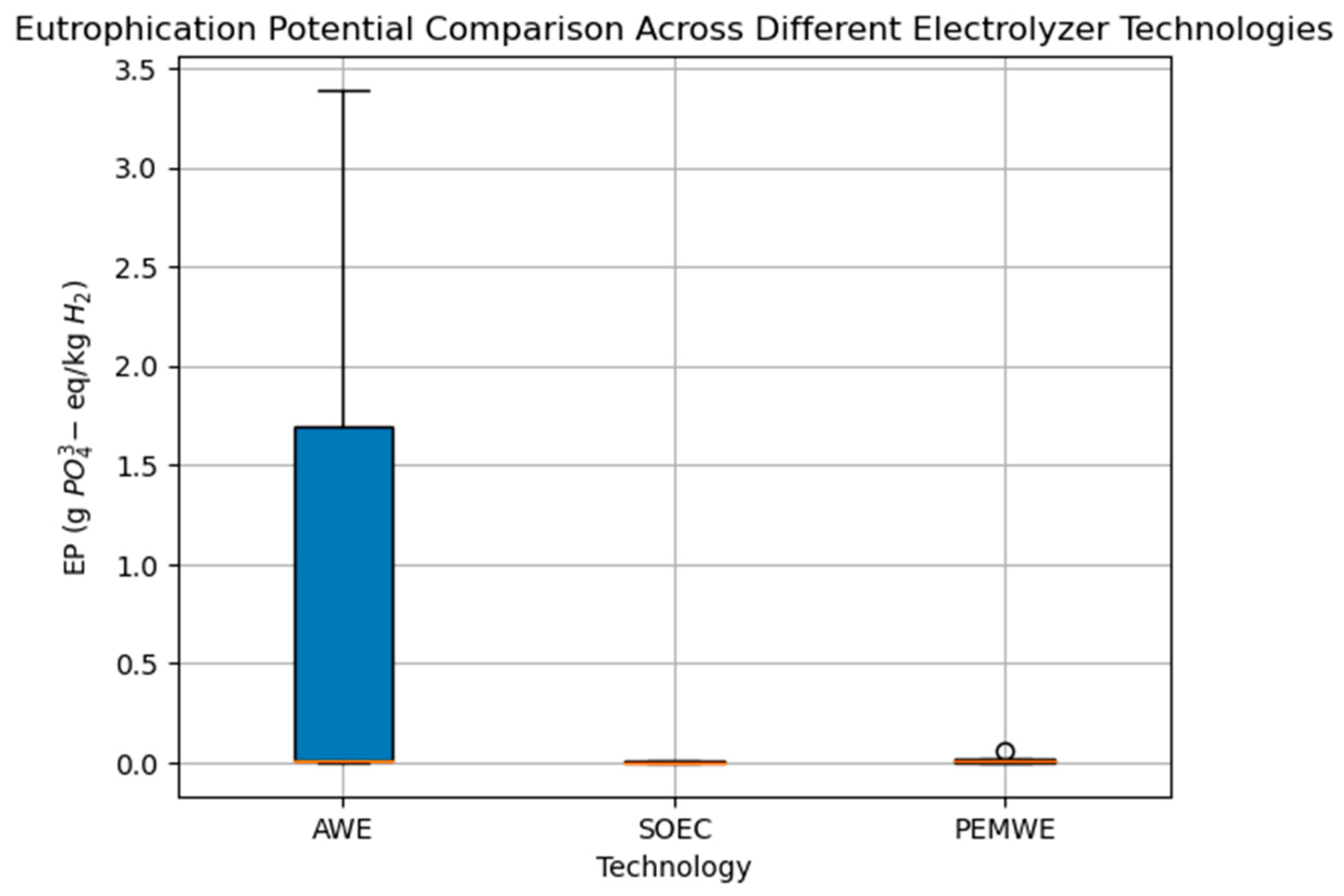
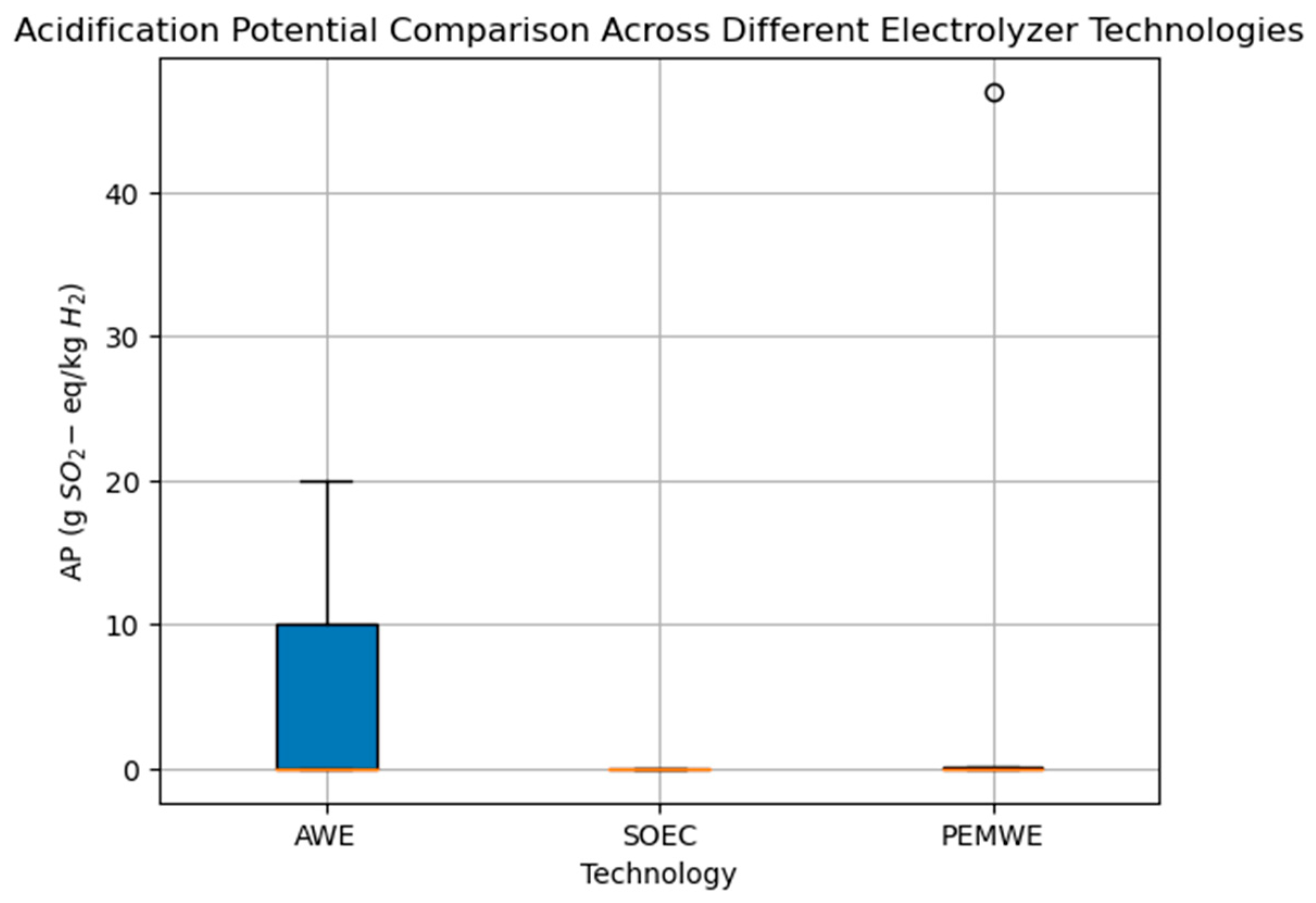
3. Summary of Environmental Impacts Result

Three important impact categories concerning the LCA of hydrogen in the review studied were selected, including global warming potential (GWP), acidification potential (AP), and eutrophication potential (EP). These three impact categories were extracted from eight studies, including Lundberg (2019), Sundin (2019), Wilkinson et al. (2023), Gerhardt-Mörsdorf et al. (2024), Giraldi et al. (2015), Zhao and Pedersen (2018), Bareiß et al. (2019), and Yang et al. (2024) [1,21,22,39,56,58,61,62]. Figure 6 illustrates GWP comparison across different electrolysis systems, wherein it is structured to compare the GWP across different hydrogen production technologies based on various energy sources. The box plot visualizes the GWP of cradle-to-gate scenarios that produce hydrogen with a purity of at least 99.9% for three electrolysis technologies: alkaline water electrolysis, solid oxide electrolysis cell, and polymer electrolyte membrane water electrolysis.
Moreover, Figure 7 demonstrates that the AWE range varies from about 1 to slightly above 30 kg CO2 eq/kg H2. This wide range indicates significant variability in GWP based on different operational settings, materials, or energy sources used in the electrolyzers. Additionally, SOEC depicts a much narrower range, from just above 0 to about 5 kg CO2 eq/kg H2, indicating more consistent results, which might be due to more uniform technology implementation or less variability in the electricity mixes used. Furthermore, PEMWE also shows a broader range from around 0.5 to slightly below 30 kg CO2 eq/kg H2, similar to AWE, which suggests variability in the operational or material efficiencies as well as the energy sources.
On the other hand, SOEC shows a higher median GWP than AWE, suggesting generally higher CO2 emissions. This median range is narrower than PEMWE, which implies less variability in the GWP data for SOEC. Additionally, it includes an outlier at the upper range, indicating a scenario where the GWP was significantly higher than typical values. It is crucial to mention that Lundberg (2019) and Sundin (2019) determined these values under specific conditions and assumptions, including a particular hydrogen production energy source and system boundaries set from cradle to gate [21,22].
Both AWE and PEMWE technologies display outliers, with AWE having one high outlier close to 32 and PEMWE having two outliers near 30 and 33. These outliers suggest that the GWP can significantly exceed typical values under certain conditions (possibly involving less efficient operations or non-renewable energy sources). SOEC shows no outliers, underscoring its relative consistency and potentially lowering GWP risk. In Giraldi et al.‘s (2015) study on the environmental impacts of hydrogen production via SOEC, nuclear power is the energy provider, so this technology’s diagram shows a low GWP [58].
The results are highly dependent on the type of electricity used (renewable vs. non-renewable sources), as the majority of the environmental impact for these technologies comes from electricity consumption during hydrogen production. Additionally, The evolution of energy sources within the electricity mix over time helps decrease the GWP and impacts the cumulative energy demand indicator [1]. The results in relation to the Wilkinson 2023 study were only extracted based on the production of green hydrogen and GWP under varying performance conditions. The GWP for AWE using wind energy ranges from 1.19 kg CO2 eq/kg H2 at the lower end to 4.45 kg CO2 eq/kg H2 at the higher end. Nevertheless, we considered this scenario to be the lowest, highest, and average rate in this study. The energy provider for the study of Gerhardt-Mörsdorf et al. (2024) is stated for different scenarios, first with the state-of-the-art plant operated with the German electricity grid mix and then with the decarbonized energy system [61]. In Zhao and Schrøder Pedersen’s (2018) study [56], the LCA of PEM water electrolysis based on electricity from wind turbines was conducted, which justifies the low environmental impact of the hydrogen produced. The analysis reveals that SOEC generally demonstrates a lower and more consistent GWP across studies, likely benefiting from higher operating temperatures and possibly more efficient electricity use. AWE and PEMWE show higher variability, indicating their performance is more sensitive to the type of electricity used (e.g., renewable vs. non-renewable) and operational efficiencies. The presence of high outliers in AWE and PEMWE suggests that under less optimal conditions, these technologies can have a significantly higher environmental impact.
As the result of Figure 6, the LCA findings show that the environmental impact of hydrogen production is significantly influenced by the energy source used for electrolysis. Utilizing renewable energy sources reduces the carbon footprint, underscoring the importance of the energy mix in assessing environmental impacts.
Figure 7 provides information on the eutrophication potential among technologies, quantified in grams of phosphate equivalent per kg of hydrogen (g PO₄3-eq/kg H2) of the reviewed studies. While GWP is often highlighted as a significant environmental concern in hydrogen production, the EP is less frequently addressed in studies, making these findings particularly valuable.
It illustrates that while some electrolyzer technologies generally exhibit low EP values, specific conditions or processes can lead to significantly higher potential impacts, as seen in the Yang et al. (2024) study [62] for AWL. The SOEC technology generally shows lower or comparable EP values to other technologies where data is available, but it is evident that data specifically for SOEC is limited.
This lack of comprehensive data across multiple studies could indicate an underrepresentation or insufficient exploration of the EP impacts of SOEC technology, highlighting a gap in the existing research. To address this gap, more targeted studies examining the EP of SOEC technology are needed to ensure an accurate and thorough assessment of its environmental impacts compared to other electrolyzer technologies. This would help make more informed decisions based on environmental considerations regarding technology adoption.
Figure 8 compares the acidification potential of different reviewed studies based on three influential impact categories on the LCA of hydrogen through production via water electrolysis technology. The potential is measured in grams of SO2-equivalent per kg of hydrogen (gSO2-eq/kg H2). This box plot visually compares the acidification potential for the technologies AWE, SOEC, and PEMWE based on the data analysis of different studies including Lundberg (2019), Sundin (2019), Wilkinson et al. (2023), Gerhardt-Mörsdorf et al. (2024), Giraldi et al. (2015), Zhao and Pedersen (2018), Bareiß et al. (2019) and Yang et al. (2024) [1,21,22,39,56,58,61,62].
The significant difference in AP between AWE and the other two technologies (SOEC and PEMWE) could be due to several factors, such as the type of energy source used (renewable vs. non-renewable), operational efficiencies, or specific technological attributes. AWE’s higher variability and potential peaks suggest that its environmental impact in terms of acidification could be more sensitive to changes in operational conditions or energy or raw material inputs. The minimal impact shown by SOEC and PEMWE highlights their environmental advantage in reducing acidification, making them potentially more favorable choices where acid rain or soil acidification are critical environmental concerns.

4. Discussion

Significant steps have been taken to explore hydrogen production technologies via water electrolysis to assess their environmental impacts, specifically through the lens of LCA, which integrates findings across various studies and focuses on three critical impact categories: GWP, AP, and EP.
The variability in the GWP of different electrolysis technologies—AWE, SOEC, and PEMWE—is pronounced and driven by differences in electricity sources, operational efficiencies, and technological implementations. Notably, the reviewed SOEC studies demonstrate a lower and more consistent GWP, attributed to its higher operational temperatures and potentially more efficient electricity use. On the contrary, AWE and PEMWE show higher variability, showing their sensitivity to the type of electricity used and operational conditions. This sensitivity is particularly evident in scenarios where non-renewable energy sources or less efficient operations come into play, significantly increasing the GWP.
The results indicate considerable differentiation between the technologies in terms of AP. AWE generally exhibits higher variability and potential peaks in AP, suggesting a higher sensitivity to changes in operational conditions or the types of energy and raw materials used. In contrast, SOEC and PEMWE demonstrate minimal impacts, highlighting their environmental advantages in contexts where acid rain or soil acidification are concerns.
Furthermore, the discussion of EP reveals a less frequently explored impact area in hydrogen production studies. The available data suggests that while some technologies typically show low EP values, specific conditions or processes can significantly increase potential impacts. This variation features the need for more comprehensive data, particularly for technologies like SOEC, where data limitations suggest a possible underrepresentation of their environmental impacts.
Overall, the environmental impact of hydrogen production is critically dependent on the choice of energy source used for electrolysis. Utilizing renewable energy sources can dramatically reduce these technologies’ carbon footprint, emphasizing the energy mix’s importance in assessing environmental impacts. This integrated understanding is vital for making informed decisions regarding technology adoption based on comprehensive environmental considerations and the evolving landscape of energy resources.

5. Conclusions

Currently, numerous technologies are available for hydrogen production, each differing in parameters such as process efficiency and energy requirements [1].
The comparative LCA of hydrogen production technologies through water electrolysis reviewed in this study highlights the variability in environmental impacts associated with different electrolysis methods: AWE, PEMW, SOEC, and AEMWE. Through meticulous analysis across various technologies, we have identified significant variabilities in environmental impact categories: global warming potential (GWP), acidification potential (AP), and eutrophication potential (EP).
The LCA findings highlight that the environmental impact of hydrogen production mainly depends on the energy source used during electrolysis and is further influenced by the efficiency of the respective electrolysis technology as well as the materials used, especially regarding the electrolyte (e.g., AP in the case of AWE). Utilizing renewable energy sources can substantially reduce the carbon footprint, emphasizing the importance of the energy mix in evaluating environmental impacts. Additionally, key advancements in membrane technology and electrocatalysts have been identified, enhancing the efficiency and sustainability of WE systems.
The study emphasizes the need for ongoing research to enhance efficiency and lower the costs of electrolysis technologies. Innovations in materials science, particularly in catalysts and membranes, have the potential to yield substantial advancements. Furthermore, it is crucial to optimize the integration with renewable energy sources to realize these technologies’ environmental benefits fully. Moreover, the shift to green hydrogen will reduce the potential for capturing economic rents similar to those generated by fossil fuels, which currently contribute approximately 2% to the global GDP [63].

Author Contributions

Conceptualization, N.S. and S.G.-C.; investigation and writing—original draft preparation, N.S.; supervision, review and editing, S.G.-C. All authors have read and agreed to the published version of the manuscript.

Funding

This research received no external funding.

Conflicts of Interest

The authors declare no conflict of interest.

References

  1. Bareiß, K.; Rua, C.; Möckl, M.; Hamacher, T. Life cycle assessment of hydrogen from proton exchange membrane water electrolysis in future energy systems. Appl. Energy 2019, 237, 862–872. [Google Scholar] [CrossRef]
  2. Meyer, Q.; Zeng, Y.; Zhao, C. In Situ and Operando Characterization of Proton Exchange Membrane Fuel Cells. Adv. Mater. 2019, 31, 1901900. [Google Scholar] [CrossRef] [PubMed]
  3. Aouali, F.Z.; Becherif, M.; Tabanjat, A.; Emziane, M.; Mohammedi, K.; Krehi, S.; Khellaf, A. Modelling and Experimental Analysis of a PEM Electrolyser Powered by a Solar Photovoltaic Panel. Energy Procedia 2014, 62, 714–722. [Google Scholar] [CrossRef]
  4. BP P.L.C. Full Report—BP Statistical Review of World Energy. 2019. Available online: https://www.bp.com/content/dam/bp/business-sites/en/global/corporate/pdfs/energy-economics/statistical-review/bp-stats-review-2019-full-report.pdf (accessed on 1 May 2024).
  5. BP P.L.C. Full Report—BP Statistical Review of World Energy. 2022. Available online: https://www.bp.com/content/dam/bp/business-sites/en/global/corporate/pdfs/energy-economics/statistical-review/bp-stats-review-2022-full-report.pdf (accessed on 1 May 2024).
  6. Kumar, S.S.; Lim, H. An overview of water electrolysis technologies for green hydrogen production. Energy Rep. 2022, 8, 13793–13813. [Google Scholar] [CrossRef]
  7. Rat: EUCO. Tagung des Europäischen Rates—Schlussfolgerungen. Available online: https://www.parlament.gv.at/gegenstand/XXVII/EU/190883 (accessed on 1 May 2024).
  8. Gül, M.; Akyüz, E. Hydrogen Generation from a Small-Scale Solar Photovoltaic Thermal (PV/T) Electrolyzer System: Numerical Model and Experimental Verification. Energies 2020, 13, 2997. [Google Scholar] [CrossRef]
  9. Miller, H.A.; Bouzek, K.; Hnat, J.; Loos, S.; Bernäcker, C.I.; Weißgärber, T.; Röntzsch, L.; Meier-Haack, J. Green hydrogen from anion exchange membrane water electrolysis: A review of recent developments in critical materials and operating conditions. Sustain. Energy Fuels 2020, 4, 2114–2133. [Google Scholar] [CrossRef]
  10. Zhao, G.; Kraglund, M.R.; Frandsen, H.L.; Wulff, A.C.; Jensen, S.H.; Chen, M.; Graves, C.R. Life cycle assessment of H2O electrolysis technologies. Int. J. Hydrogen Energy 2020, 45, 23765–23781. [Google Scholar] [CrossRef]
  11. Fraunhofer. Economical and Resource-Saving Green Hydrogen. 2023. Available online: https://www.fraunhofer.de/content/dam/zv/en/press-media/2023/ifam-economical-and-resource-saving-green-hydrogen-2.pdf (accessed on 29 August 2023).
  12. Strogies, M.; Gniffke, P. Berichterstattung unter der Klimarahmenkonvention der Vereinten Nationen und dem Kyoto-Protokoll; Tech. Rep.; Umweltbundesamt: Vienna, Austria, 2017. [Google Scholar]
  13. Hydrogen Council. Hydrogen Decarbonization Pathways—A Life-Cycle Assessment. 2021. Available online: https://hydrogencouncil.com/wp-content/uploads/2021/01/Hydrogen-Council-Report_Decarbonization-Pathways_Part-1-Lifecycle-Assessment.pdf (accessed on 12 July 2023).
  14. Nikolaidis, P.; Poullikkas, A. A comparative overview of hydrogen production processes. Renew. Sustain. Energy Rev. 2017, 67, 597–611. [Google Scholar] [CrossRef]
  15. Kumar, S.S.; Himabindu, V. Hydrogen production by PEM water electrolysis—A review. Mater. Sci. Energy Technol. 2019, 2, 442–454. [Google Scholar] [CrossRef]
  16. European Commission; Joint Research Centre; Carrara, S.; Bobba, S.; Blagoeva, D.; Dias, P.A.; Cavalli, A.; Georgitzikis, K.; Grohol, M.; Itul, A.; et al. Supply Chain Analysis and Material Demand Forecast in Strategic Technologies and Sectors in the EU—A Foresight Study; Publications Office of the European Union: Luxembourg, 2023. [Google Scholar]
  17. Ajanovic, A.; Sayer, M.; Haas, R. The economics and the environmental benignity of different colors of hydrogen. Int. J. Hydrogen Energy 2022, 47, 24136–24154. [Google Scholar] [CrossRef]
  18. Woody, A.; Carlson, H. State of Play: Hydrogen in 2020|White & Case LLP. 2023. Available online: https://www.whitecase.com/insight-alert/state-play-hydrogen-2020 (accessed on 6 July 2023).
  19. Ingale, G.U.; Kwon, H.-M.; Jeong, S.; Park, D.; Kim, W.; Bang, B.; Lim, Y.-I.; Kim, S.W.; Kang, Y.-B.; Mun, J.; et al. Assessment of Greenhouse Gas Emissions from Hydrogen Production Processes: Turquoise Hydrogen vs. Steam Methane Reforming. Energies 2022, 15, 8679. [Google Scholar] [CrossRef]
  20. Okoye, C.O.; Jones, I.; Zhu, M.; Zhang, Z.; Zhang, D. Manufacturing of carbon black from spent tyre pyrolysis oil—A literature review. J. Clean. Prod. 2021, 279, 123336. [Google Scholar] [CrossRef]
  21. Sundin, C. Environmental Assessment of Electrolyzers for Hydrogen Gas Production. 2019. Available online: https://www.semanticscholar.org/paper/Environmental-Assessment-of-Electrolyzers-for-Gas-Sundin/1a6dcdd528ef4a9f303f5311e564f1a2efb586a0 (accessed on 1 May 2024).
  22. Lundberg, S. Comparative LCA of Electrolyzers for Hydrogen Gas Production. KTH, Sustainable Development, Environmental science and Engineering, Document Number 19543. Available online: https://www.semanticscholar.org/paper/Comparative-LCA-of-Electrolyzers-for-Hydrogen-Gas-Lundberg/b28594280c1940ba426b1a6f7b05e47205933164 (accessed on 1 May 2024).
  23. Papakonstantinou, G.; Algara-Siller, G.; Teschner, D.; Vidaković-Koch, T.; Schlögl, R.; Sundmacher, K. Degradation study of a proton exchange membrane water electrolyzer under dynamic operation conditions. Appl. Energy 2020, 280, 115911. [Google Scholar] [CrossRef]
  24. Kanz, O.; Bittkau, K.; Ding, K.; Rau, U.; Reinders, A. Review and harmonization of the life-cycle global warming impact of PV-powered hydrogen production by electrolysis. Front. Electron. 2021, 2, 711103. [Google Scholar] [CrossRef]
  25. Schmidt, P.; Weindorf, W.; Roth, A.; Batteiger, V.; Riegel, F. Power-to-Liquids Potentials and Perspectives for the Future Supply of Renewable Aviation Fuel; Umweltbundesamt: Dessau-Roßlau, Germany, 2016; Available online: https://www.umweltbundesamt.de/sites/default/files/medien/377/publikationen/161005_uba_hintergrund_ptl_barrierrefrei.pdf (accessed on 1 May 2024).
  26. Peng, L.; Wei, Z. Catalyst Engineering for Electrochemical Energy Conversion from Water to Water: Water Electrolysis and the Hydrogen Fuel Cell. Engineering 2020, 6, 653–679. [Google Scholar] [CrossRef]
  27. Liu, T.; Wang, X.; Jiang, X.; Deng, C.; Niu, S.; Mao, J.; Zeng, W.; Liu, M.; Liao, H. Mechanism of corrosion and sedimentation of nickel electrodes for alkaline water electrolysis. Mater. Chem. Phys. 2023, 303, 127806. [Google Scholar] [CrossRef]
  28. Brauns, J.; Turek, T. Alkaline Water Electrolysis Powered by Renewable Energy: A Review. Processes 2020, 8, 248. [Google Scholar] [CrossRef]
  29. Vincent, I.; Bessarabov, D. Low cost hydrogen production by anion exchange membrane electrolysis: A review. Renew. Sustain. Energy Rev. 2018, 81, 1690–1704. [Google Scholar] [CrossRef]
  30. Schmidt, O.; Gambhir, A.; Staffell, I.; Hawkes, A.; Nelson, J.; Few, S. Future cost and performance of water electrolysis: An expert elicitation study. Int. J. Hydrogen Energy 2017, 42, 30470–30492. [Google Scholar] [CrossRef]
  31. Faid, A.Y.; Xie, L.; Barnett, A.O.; Seland, F.; Kirk, D.; Sunde, S. Effect of anion exchange ionomer content on electrode performance in AEM water electrolysis. Int. J. Hydrogen Energy 2020, 45, 28272–28284. [Google Scholar] [CrossRef]
  32. Ferreira, A.P.R.A.; Oliveira, R.C.P.; Mateus, M.M.; Santos, D.M.F. A Review of the Use of Electrolytic Cells for Energy and Environmental Applications. Energies 2023, 16, 1593. [Google Scholar] [CrossRef]
  33. Sugawara, Y.; Sankar, S.; Miyanishi, S.; Illathvalappil, R.; Gangadharan, P.K.; Kuroki, H.; Anilkumar, G.M.; Yamaguchi, T. Anion Exchange Membrane Water Electrolyzers: An Overview. J. Chem. Eng. Jpn. 2023, 56, 2210195. [Google Scholar] [CrossRef]
  34. Riedel, M.; Heddrich, M.P.; Ansar, A.; Fang, Q.; Blum, L.; Friedrich, K.A. Pressurized operation of solid oxide electrolysis stacks: An experimental comparison of the performance of 10-layer stacks with fuel electrode and electrolyte supported cell concepts. J. Power Sources 2020, 475, 228682. [Google Scholar] [CrossRef]
  35. Bender, G.; Carmo, M.; Smolinka, T.; Gago, A.; Danilovic, N.; Mueller, M.; Ganci, F.; Fallisch, A.; Lettenmeier, P.; Friedrich, K.A.; et al. Initial approaches in benchmarking and round robin testing for proton exchange membrane water electrolyzers. Int. J. Hydrogen Energy 2019, 44, 9174–9187. [Google Scholar] [CrossRef]
  36. Bock, R.; Karoliussen, H.; Seland, F.; Pollet, B.G.; Thomassen, M.S.; Holdcroft, S.; Burheim, O.S. Measuring the thermal conductivity of membrane and porous transport layer in proton and anion exchange membrane water electrolyzers for temperature distribution modeling. Int. J. Hydrogen Energy 2020, 45, 1236–1254. [Google Scholar] [CrossRef]
  37. Shirvanian, P.; van Berkel, F. Novel components in Proton Exchange Membrane (PEM) Water Electrolyzers (PEMWE): Status, challenges and future needs. A mini review. Electrochem. Commun. 2020, 114, 106704. [Google Scholar] [CrossRef]
  38. Siracusano, S.; Trocino, S.; Briguglio, N.; Baglio, V.; Aricò, A.S. Electrochemical Impedance Spectroscopy as a Diagnostic Tool in Polymer Electrolyte Membrane Electrolysis. Materials 2018, 11, 1368. [Google Scholar] [CrossRef] [PubMed]
  39. Wilkinson, J.; Mays, T.; McManus, M. Review and meta-analysis of recent life cycle assessments of hydrogen production. Clean. Environ. Syst. 2023, 9, 100116. [Google Scholar] [CrossRef]
  40. Laveissiere, G.; Demoulin, M.; Calvet, R. Overall Assessment of Electrolyser Sustainability. Available online: https://www.sia-partners.com/system/files/document_download/file/2022-11/Electrolyzer%20materials.pdf (accessed on 1 May 2024).
  41. Eikeng, E.; Makhsoos, A.; Pollet, B.G. Critical and strategic raw materials for electrolysers, fuel cells, metal hydrides and hydrogen separation technologies. Int. J. Hydrogen Energy 2024, 71, 433–464. [Google Scholar] [CrossRef]
  42. Zignani, S.C.; Faro, M.L.; Carbone, A.; Italiano, C.; Trocino, S.; Monforte, G.; Aricò, A.S. Performance and stability of a critical raw materials-free anion exchange membrane electrolysis cell. Electrochim. Acta 2022, 413, 140078. [Google Scholar] [CrossRef]
  43. Enapter. Enapter Datasheet EL 2.1 EN. Available online: https://handbook.enapter.com/electrolyser/el21/downloads/Enapter_Datasheet_EL21_EN.pdf (accessed on 1 May 2024).
  44. Anantharaj, S.; Aravindan, V. Developments and Perspectives in 3d Transition-Metal-Based Electrocatalysts for Neutral and Near-Neutral Water Electrolysis. Adv. Energy Mater. 2020, 10, 1902666. [Google Scholar] [CrossRef]
  45. Lei, Z.; Wang, T.; Zhao, B.; Cai, W.; Liu, Y.; Jiao, S.; Li, Q.; Cao, R.; Liu, M. Recent Progress in Electrocatalysts for Acidic Water Oxidation. Adv. Energy Mater. 2020, 10, 2000478. [Google Scholar] [CrossRef]
  46. Zhang, H.; Su, S.; Chen, X.; Lin, G.; Chen, J. Performance evaluation and optimum design strategies of an acid water electrolyzer system for hydrogen production. Int. J. Hydrogen Energy 2012, 37, 18615–18621. [Google Scholar] [CrossRef]
  47. Koponen, J.; Kosonen, A.; Ruuskanen, V.; Huoman, K.; Niemelä, M.; Ahola, J. Control and energy efficiency of PEM water electrolyzers in renewable energy systems. Int. J. Hydrogen Energy 2017, 42, 29648–29660. [Google Scholar] [CrossRef]
  48. Dobó, Z.; Palotás, Á. Impact of the voltage fluctuation of the power supply on the efficiency of alkaline water electrolysis. Int. J. Hydrogen Energy 2016, 41, 11849–11856. [Google Scholar] [CrossRef]
  49. Bundesministerium für Wirtschaft und Energie (BMWi). Nationales Reformprogramm. Available online: https://www.bmwk.de/Redaktion/DE/Publikationen/Energie/die-nationale-wasserstoffstrategie.pdf?__blob=publicationFile&v=11 (accessed on 1 May 2024).
  50. International Energy Agency—IEA. Renewable Energy Statistics 2022; The International Renewable Energy Agency: Abu Dhabi, United Arab Emirates, 2022. [Google Scholar]
  51. Ozbilen, A.; Dincer, I.; Rosen, M.A. Environmental evaluation of hydrogen production via thermochemical water splitting using the Cu–Cl Cycle: A parametric study. Int. J. Hydrogen Energy 2011, 36, 9514–9528. [Google Scholar] [CrossRef]
  52. DIN 14040; Environmental Management-Life Cycle Assessment-Principles and Framework (ISO 14040:2006 + Amd 1:2020); German Version EN ISO14040:2006 + A1:2020. DIN: Berlin, Germany, 2006. [CrossRef]
  53. DIN 14044; Environmental Management-Life Cycle Assessment-Requirements and Guidelines (ISO 14044:2006 + Amd 1:2017 + Amd 2:2020); German Version EN ISO 14044:2006 + A1:2018 + A2:2020. DIN: Berlin, Germany, 2006. [CrossRef]
  54. Lozanovski, A.; Schuller, O.; Faltenbacher, M. FC-Hy Guide—Guidance Document for Performing LCAs on Fuel Cells and H2 Technologies. Available online: https://hytechcycling.eu/wp-content/uploads/HY-Guidance-Document.pdf (accessed on 1 May 2024).
  55. Ecoinvent. System Models. 2018. Available online: https://support.ecoinvent.org/system-models#Allocation_classification (accessed on 1 May 2024).
  56. Zhao, G.; Pedersen, A.S. Life Cycle Assessment of Hydrogen Production and Consumption in an Isolated Territory. Procedia CIRP 2018, 69, 529–533. [Google Scholar] [CrossRef]
  57. Häfele, S.; Hauck, M.; Dailly, J. Life cycle assessment of the manufacture and operation of solid oxide electrolyser components and stacks. Int. J. Hydrogen Energy 2016, 41, 13786–13796. [Google Scholar] [CrossRef]
  58. Giraldi, M.R.; François, J.-L.; Cecilia, M. Life cycle assessment of hydrogen production from a high temperature electrolysis process coupled to a high temperature gas nuclear reactor. Int. J. Hydrogen Energy 2015, 40, 4019–4033. [Google Scholar] [CrossRef]
  59. Bhandari, R.; Trudewind, C.A.; Zapp, P. Life cycle assessment of hydrogen production via electrolysis—A review. J. Clean. Prod. 2014, 85, 151–163. [Google Scholar] [CrossRef]
  60. LBST. E3database. 2009. Available online: https://www.e3database.com/index.html (accessed on 17 May 2024).
  61. Gerhardt-Mörsdorf, J.; Peterssen, F.; Burfeind, P.; Benecke, M.; Bensmann, B.; Hanke-Rauschenbach, R.; Minke, C. Life Cycle Assessment of a 5 MW Polymer Exchange Membrane Water Electrolysis Plant. Adv. Energy Sustain. Res. 2024, 5, 2300135. [Google Scholar] [CrossRef]
  62. Yang, S.; Mao, D.; Yu, Z.; Ma, W.; Ma, L.; Li, X.; Xi, F. Comparison of life cycle assessment between hydrogen production from silicon waste and alkaline water electrolysis. Sci. Total Environ. 2024, 920, 171065. [Google Scholar] [CrossRef] [PubMed]
  63. IRENA. Renewable Energy Statistics 2022; The International Renewable Energy Agency: Abu Dhabi, United Arab Emirates, 2022. [Google Scholar]
Figure 1. The different technologies for hydrogen production are based on the energy source employed and inspired by [15,16].
Energies 17 03968 g001
Figure 2. Schematic figure of the AWE cell according to [15].
Energies 17 03968 g002
Figure 3. Schematic figure of the AEMWE cell according to [15,33].
Energies 17 03968 g003
Figure 4. Schematic figure of the SOEC according to [15].
Energies 17 03968 g004
Figure 5. Schematic figure of the PEMWE cell according to [15,33].
Energies 17 03968 g005
Figure 6. GWP comparison across different electrolysis systems.
Energies 17 03968 g006
Figure 7. Eutrophication potential comparison across different electrolyzer technologies.
Energies 17 03968 g007
Figure 8. Acidification potential comparison across different electrolyzer technologies.
Energies 17 03968 g008
Table 1. Definition of technology readiness levels according to EU Commission 2014 [25].
TRLDescription
1basic principles observed
2technology concept formulated
3experimental proof of concept
4technology validated in the lab
5technology validated in relevant environment (industrially relevant environment in the case of key enabling technologies)
6technology demonstrated in relevant environment (industrially relevant environment in the case of key enabling technologies)
7system prototype demonstration in an operational environment
8the system completed and qualified
9the actual system proved in an operational environment (competitive manufacturing in the case of key enabling technologies or in space)
Table 2. Comparison of key water electrolysis technologies.
TechnologyAdvantagesDisadvantagesCritical Raw MaterialTechnology MaturityOperating TemperatureSystem Lifetime (h)Source
AWENon-noble catalyst layer (CL)
Low-cost and non-PGM CL
Energy efficiency 70–80%.
Stable over long periods.
Low system costs (around 800–1000 EUR/kW installed capacity).
Formation of carbonate on the electrode.
Low purity and crossover of gases.
Low operational pressure.
Low dynamic operation.
Corrosive liquid electrolyte.
Nickel
Chromium
Zinc
Commercially mature
TRL 9
70–90 °C60,000–90,000[9,15,39,40,41]
PEMWEHigh current densities.
Compact system design.
Fast responses.
High purity of gases.
Energy efficiency 80%.
High dynamic operation.
Noble and expensive metal CL.
Acidic corrosive.
Possible low durability.
Currently, high system costs of around 1000–1500 EUR/kW installed capacity.
Titanium
Platinum
Iridium
Chromium
Commercialization at small scale
TRL 6–8
50–80 °C20,000–60,000[15,30,34,39,40,41,42]
AEMWELow-cost transition metal catalysts.
Non-corrosive electrolyte.
High operating pressure.
Compact cell design.
Absence of leaking.
Low current densities.
Membrane degradation.
Excessive catalyst loading.
Critical raw material-freeLaboratory stage
TRL 2–3
40–60 °C-[9,16,29,31,39,41,42,43]
SOECHigh working Pressure.
Non-noble CL.
Energy efficiency 90–100%.
Large system design.
Low durability.
High system costs around 1800–2300 €/kW installed capacity.
Yttrium
Zirconium
Gallium
Commercialization in the near term
TRL 5
700–850 °C10,000[9,15,16,31,39,40,41]
Table 3. Strategic and critical raw material employed in the water electrolyzer [16].
Supply RiskStrategic Raw MaterialSupply RiskCritical Raw Material
4.1Magnesium5.3HREE (rest)
4.0REE(Magnet)4.4Niobium
3.8Boron3.5LREE (rest)
2.7PGM2.6Strontium
1.8Natural graphite2.4Scandium
1.7Cobalt2.3Vanadium
1.4Silicon metal1.3Baryte
1.2Tungsten1.3Tantalum
1.2Manganese1.2Aluminium
0.5Nickel
0.1Copper
Table 4. Critical gap analysis of existing literature in the LCA of hydrogen production via the water electrolysis system.
StudyTechnologyPower SupplyHighest Factor on Environmental Impact Category or Status of ItThe LCIA Method
Wilkinson, et al. (2023) [39]literature dataliterature dataGlobal warming potential (GWP)Literature data
Sundin (2019) [21]PEMWE, AWEGrid mixElectrolyzer lifetime and current densityCML 2001
Zhao and Schrøder Pedersen, (2018) [56]PEMWEWind turbinesGlobal warming potentialILCD 2011 Midpoint
Häfele, et al. (2016) [57]SOEC94% nuclear primary energyHighest from the electrolysis itselfNot mentioned
Giraldi, et al. (2015) [58]SOECNuclear power supplyThe electrolysis cell and hydrogen production processes.ReCiPe midpoint
Bhandari, et al. (2014) [59]PEMWE, AWE, SOEC×Global warming potential (GWP) and Acidification potential (AP)literature data
Our Studyliterature dataliterature dataGWP, AP, and Eutrophication potentialLiterature data
Disclaimer/Publisher’s Note: The statements, opinions and data contained in all publications are solely those of the individual author(s) and contributor(s) and not of MDPI and/or the editor(s). MDPI and/or the editor(s) disclaim responsibility for any injury to people or property resulting from any ideas, methods, instructions or products referred to in the content.

