Abstract
Electromagnetic forces can lead to the structural failure of power transformers due to extreme loading conditions, vibration, and/or fatigue. Therefore, studying the nature and the magnitude of these forces is a key task in the design and failure analysis of such important equipment. Keeping this issue in mind, this work aims at conducting a numerical analysis in order to evaluate the mechanical stresses and displacements of windings in power transformers due to the action of electromagnetic forces. With this purpose, a finite element model is developed considering electromagnetic and mechanical effects assuming short-circuit conditions. The study compares the cases employing copper and aluminum windings with header tap, in different temperatures. The model developed in this work is verified against analytical solutions. The numerical calculations allow for performing a detailed analysis in terms of the distribution of both displacements and stresses along the windings, which is of great relevance for identifying critical structural points and avoiding structural failure. Overall, the obtained results demonstrate that the finite element model is a useful tool for the structural design of power transformers that allow for investigating and optimizing key aspects before manufacturing.
1. Introduction
Power transformers are devices commonly found along the power electric system. They are used to transmit and to distribute electrical energy by adjusting current and voltage levels. Additionally, its design and manufacture are complex, being among the most expensive equipment in the system, besides requiring well planned logistics [1,2,3,4].
There are numerous concerns regarding issues that could compromise the proper functioning of power transformers or even lead to their outage, potentially interrupting the continuous supply of electrical energy. Considering this, it is worth noticing that power transformers are designed to withstand nominal and overload voltages and currents; however, there may be situations in which the values considered in the design are exceeded, subjecting the device to extreme internal stresses [5,6].
One of these situations is the short-circuit, which results in significant electrical, thermal, and mechanical stresses in the electrical network and its components. During this transient fault, the transformers are exposed to high electromechanical stresses that can lead to deformations in their windings and, consequently, their failure. The winding deformation can result in, among other consequences, the rupture of solid insulation, which, in turn, may lead to internal short circuits. In the long term, deformations can reduce the asset’s lifespan [7,8,9].
In relation to the protective system, protective techniques are employed to extinguish this phenomenon and to avoid damage. However, protective devices are also prone to failure, which can prolong the time required to mitigate this transient. As a result, the devices within the electric grid have to be designed to withstand short-circuit current until its extinction. Otherwise, there can be extreme internal stresses that may lead to damage to the transformer, jeopardizing the operation of the electrical system [10].
From a design point of view, several parameters influence the mechanical durability of the windings. The conductor material is the first, but is, generally, defined by the customer. The conductor’s dimensions are defined by the designer according to the specified losses and reactance. With these defined, the withstand can be adjusted by modifying the mechanical spacer between discs and the conductor hardness.
The number and dimensions of spacers must be defined together with the thermal design. An increase in the number of spacers, or its dimensions, enhances the mechanical withstand, however, it reduces the thermal efficiency, leading to higher temperatures. Thus, the conductor hardness is the last parameter that can be modified without influencing the rest of the project. On the other hand, a harder conductor results in manufacturing issues, as it is more difficult during production and assembly, demanding more time.
In this scenario, in addition to the need for design optimization and costs reduction, it is necessary to improve these design parameters for a more reliable and robust transformer, with lower costs and time for manufacturing. For this, the electromagnetic forces and their respective stresses distributions along the windings must be obtained to be considered in the mechanical design.
The authors reported in previous papers that finite element analysis (FEA) has emerged as a crucial tool for the analysis and diagnostics of short-circuit forces in power transformers [1,11]. Numerous FEA studies have also been conducted to evaluate electromagnetic forces. However, existing modeling methods often lack detailed analyses of these forces and their distribution across transformer windings. In references [12,13,14], only radial forces were examined, while in [15], only axial forces were considered.
Many studies have focused on simulations of single-phase transformers, such as those in [9,16,17,18,19]. In [20], a three-dimensional (3D) model was employed, with windings partitioned in both the radial and axial directions, providing insight into radial force distribution around a single winding, but axial forces were solely analyzed along the axial direction. In another study [21], a 3D model of a three-phase transformer was utilized to investigate inrush electromechanical forces, yet only total forces were examined. Similarly, in [22], a 3D simulation of a single-phase transformer only analyzed forces over the height of the windings.
Given the simplified models and incomplete force analyses in the aforementioned works, the authors previously presented a comprehensive calculation of axial and radial electromagnetic forces in a three-phase transformer with concentric windings [1,11]. The methodology verified the axial and radial forces distribution, along the winding height and around the core column, in the central and lateral phases, inside and outside the core window. In addition, it was verified that the tap arrangements influenced the force behavior.
Once the electromagnetic force distribution is known, the electromechanical stresses must be evaluated. The authors presented a simplified stress analysis in a previous paper [23], considering the winding as an unique solid. As a sequence of that study, this article focuses on evaluating electromagnetic stresses in power transformers through finite element analysis under short-circuit excitation along the winding. The analyzed transformer windings were modeled according to the number of discs and the mechanical spacers between them, ensuring more precise results. First, the axial and radial force distributions were obtained. From this, the axial and radial mechanical stresses were evaluated. In addition, the windings were simulated considering copper and aluminum as the materials, at different temperatures, to compare their mechanical resistance in different conditions.
2. Electromagnetic Forces
The principle of electromagnetic stresses is based on the following physical phenomenon: when an electric current flows through a conductor immersed in a magnetic field, it experiences electromagnetic forces. This behavior is quantified and described by the Lorentz law, where the cross product of the current density () and the magnetic flux density () results in an orthogonal density force, as shown in (1) [1,6,24].
This principle is fundamental in electric motors, as the interaction between the magnetic flux and the current generates the movement of the rotor. These electromagnetic forces are also present in transformers. However, as transformers are static devices, they must be designed to support and contain these forces.
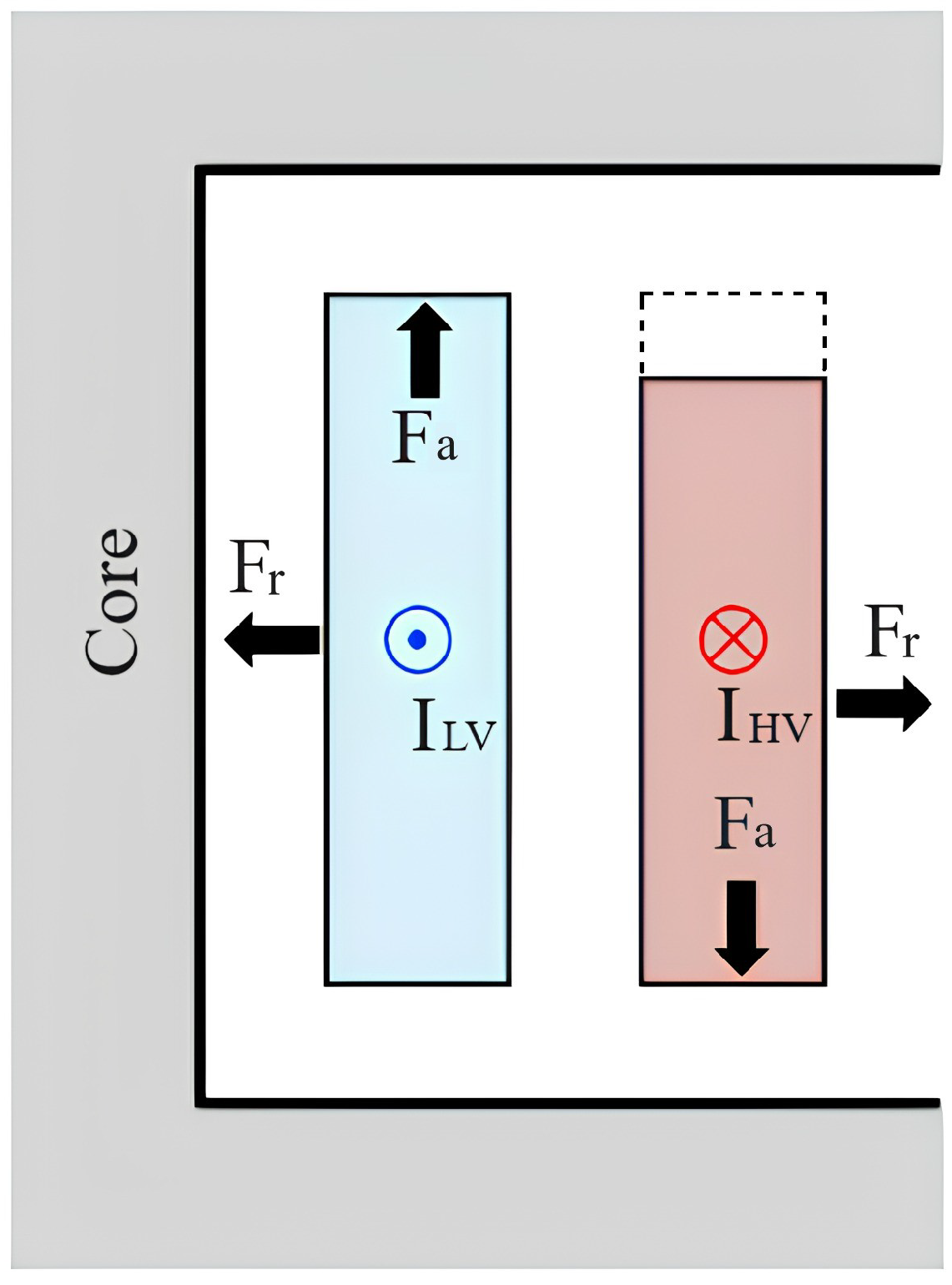
The transformer active part consists of low-voltage (LV) and high-voltage (HV) concentric windings wounded around a ferromagnetic core. As detailed in [1], the behavior of the leakage magnetic field within the transformer windings can be divided into two components: radial () and axial (). The axial component of the magnetic flux interacting with the current results in radial forces (). As a consequence of these radial forces, the external winding of a transformer is subjected to tensile stress, while the internal winding experiences compressive stress, as shown in Figure 1, which illustrates the arrangement with a tap located at the head of the external winding, represented by a dashed line.

Figure 1.
Forces in concentric windings with a tap in the head on the outer winding.
The calculation of radial forces in transformers with concentric windings is described in [24], where more details about the mathematical deduction can be found. These forces can be expressed as a product of the average axial flux and the total current of the winding, as shown in (2), which calculates the radial force per unit of winding length. To obtain the total radial force, the result from (2) was multiplied by the winding circumference , where is the average winding diameter, assumed as the average value between the internal and external diameter of the analyzed winding, as shown in (3).
where:
- : Radial force per unit length (tons/m);
- : Total radial force (tons);
- NI: Ampère-turn (A);
- h: Winding height (m);
- : Average winding diameter (m).
The axial forces () are a result of the interaction between the current and the radial component of the magnetic flux, which depends on the arrangement geometry and is difficult to determine. Thus, axial stresses are directly related to the winding arrangement [6]. In order to provide a satisfactory method to estimate the magnetic flux radial component, the Ampère-turn residual method is used [24], illustrated in Figure 2, for the arrangement with a tap located at the head of the external winding. The unbalanced arrangement is separated in two balanced arrangements. The residual Ampère-turn diagram represents the radial flux distribution along the windings, in a triangle format, with a peak value of , where a is the percentage height difference between the windings.
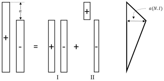
Figure 2.
Ampère-turn residual method tap located at the head of the external winding.
The arrangement with a tap located at the head of the external winding, shown in Figure 1, is considered critical with the highest axial stresses [1,11], with its Ampère-turn residual diagram shown in Figure 2. For this arrangement, the axial force , in tons, is calculated using (4), where , in meters, is the effective path of the radial flux. In this arrangement, the LV winding experiences an upward axial stress, while the HV winding undergoes a downward force, leading to an expansion of the tap of the power transformer.
The term represents only constructive dimensions and is called the permeance per unit of length in the radial direction, represented by the variable , in Equation (5). The is dimensionless and expresses the ratio between the core window and core diameter, which was studied empirically. It was observed that a lower ratio core window/diameter led to a higher axial force [24].
More details about the Ampère-turn residual method, the empirical study, and the mathematical deduction for the calculation of the axial force of other windings arrangements can be found in [24].
3. Mechanical Stresses and Strains
The electromagnetic forces resulting from high currents flowing through the windings in atypical situations generate mechanical stresses and strains in the windings. Excessive strains can result in various failures, including internal short-circuits due to possible damage to the insulating material, local overheating due to the poor circulation of the refrigerant oil, and the reduction of the mechanical supportability for future accidents due to the loosening of the spacers. One way to verify whether the winding stresses will lead to material damage (e.g., plastic yielding) that could take the transformer out of operation is ensuring that the mechanical stress does not exceed the material yield limit under loading conditions [6,25].
3.1. Copper and Aluminum Properties
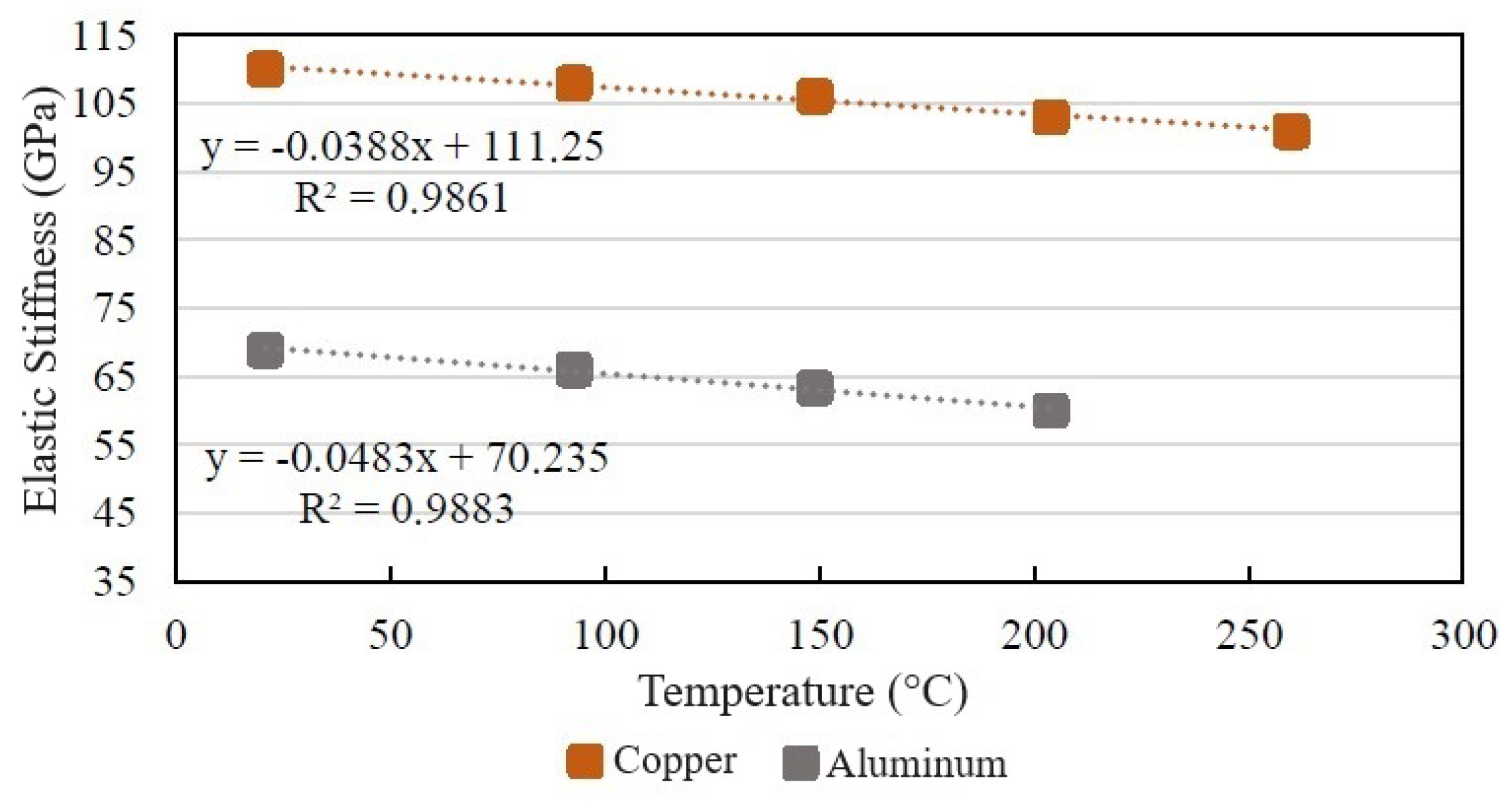
Depending on the customer specifications and the final application, the transformer windings can be designed and manufactured in copper or aluminum. On the one hand, copper has a lower electrical resistivity and higher mechanical resistivity than aluminum. On the other hand, aluminum presents lower costs and density than copper [6]. This study focuses on the mechanical deformation of the windings, where elastic stiffness is an important property to be considered, as illustrated in Figure 3, with its respective equations as a function of the operation temperature. Higher values were observed for copper than aluminum, which decreased as the temperature increased for both materials. In addition, the international standard IEC 60076-5 established 250 °C and 200 °C as the maximum temperatures for copper and aluminum, respectively, to avoid an accelerated ageing of insulation paper [26]. Based on this, the analysis presented here used 200 °C in order to compare both materials, and 115 °C as an intermediate operation temperature.

Figure 3.
Elastic stiffness according to temperature.
3.2. Axial Stresses
The stresses induced by the axial forces can cause bending deformation, which is the deflection of the conductors between the radial spacers [6,24]. This deformation can result in damage to the conductor isolation, and to a reduction in the distance between discs.
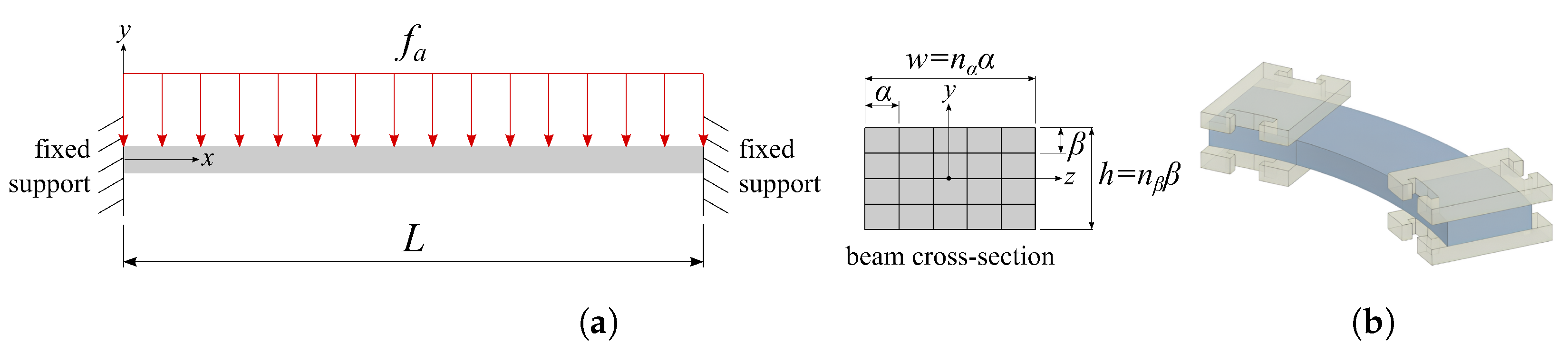
A simple way to estimate the bending stresses is idealizing the conductor as a clamped–clamped beam, as shown in Figure 4a. This model assumes that the conductors are fixed between two pairs of radial spacers, and do not experience axial displacement in this region, as illustrated in Figure 4b. Notice that the beam curvature is not considered in this simplified approach.
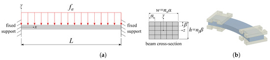
Figure 4.
Model to determine axial stresses: (a) Double-embedded beam model. (b) Disc section between radial spacers.
According to the Euler–Bernoulli theory, it is assumed that the primary stresses are the normal stresses along the longitudinal direction. These stresses are developed as a function of the bending moment M(x) at any point (x) of the beam, and are given by (6). Here, represents the longitudinal coordinate, with L being the beam length, and representing the vertical coordinate, with h being the rectangular cross-section height, while is the area moment of inertia around the z axis.
The stress will be analyzed in point , where the maximum displacement of the disc segment occurs. The equation for M(L/2) is given by (7), and is given by (8). Notice that, as an approximation, the moment of inertia of the cross-section is calculated by assuming the conductors are perfectly tied, such that the cross-section behaves as a single body.
where:
- : Axial force per length unit (N/m);
- L: Distance between the radial spacers (m);
- : Number of axial conductors;
- : Axial dimension of the conductor (m);
- : Number of radial conductors;
- : Radial dimension of the conductor (m);
Substituting (7) and (8) into (6), we can derive the axial stress in the disc segment, as expressed in (9). This allows for calculating the axial stress in the disc and determining whether it falls below the specified limit of the material.
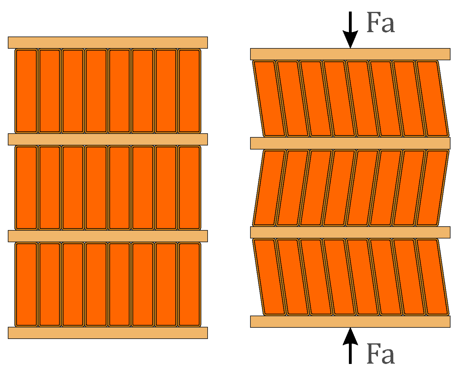
In addition, the compressive action of the axial forces can cause the inclination of the conductor in a zig-zag pattern, referred to as tilting [6,24], illustrated in Figure 5. In this failure mode, there is a rotation in the cross-section of the conductors around the perpendicular axis of symmetry. Two forces resist the tipping of these conductors: the first is related to the resistance to the torsion of the conductor, and the second is related to the frictional force that can exist between conductors in helical winding or between coils and radial spacers, in disc-type winding.

Figure 5.
Tilting effect due to axial forces.
3.3. Radial Stresses
In transformers with concentric windings, the mechanical support for the external winding depends solely on the tensile strength of the conductor, when there are no axial spacers located externally of the windings.
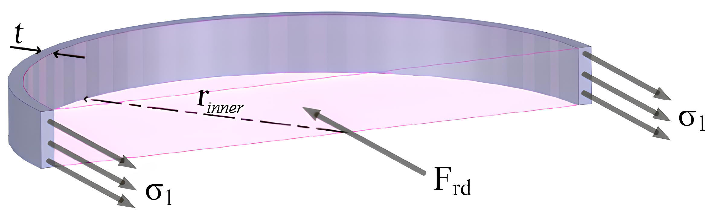
A simplified methodology to determine the mechanical radial stresses in the coils/disc of the outer winding is used by adopting the model of a thin-walled cylindrical pressure vessel, as seen in Figure 6. This is applicable when the thickness t of the winding coil/disc is significantly smaller than the internal radius of the coil.

Figure 6.
Model used to determine the radial stresses on the outer winding.
The equation for circumferential stress to cylindrical bodies is given by (10). Where is the resulting internal pressure of force , which is the total radial force in the section of the coil/disc and is the radius of the inner part of the coil/disc.
In the inner winding, a deformation known as buckling can occur, which is caused by the pressure of the coil/disc on the axial spacers [6,24]. Considering the presence of axial spacers in the inner and outer parts of the low-voltage winding, and the fact that the distance between them is small when compared with the curvature degree of the segment in between the distance of two spacers, one can estimate the radial stress using a model similar to the model used for the axial stress, in which it is considered a double-embedded beam. In this case, only the , and are altered. Therefore, also adopting a straight beam model, the radial stress between the two axial spacers is expressed by (11).
4. Finite Element Simulation
The analytical methods previously presented provide simplified tools to make a global analysis of the mechanical system. However, a more detailed evaluation, not restricted to simplifying assumptions, to achieve a more comprehensive understanding of the overall behavior of the electromagnetic forces and the resulting mechanical stresses demands a more sophisticated approach, using, e.g., the finite element method (FEM).
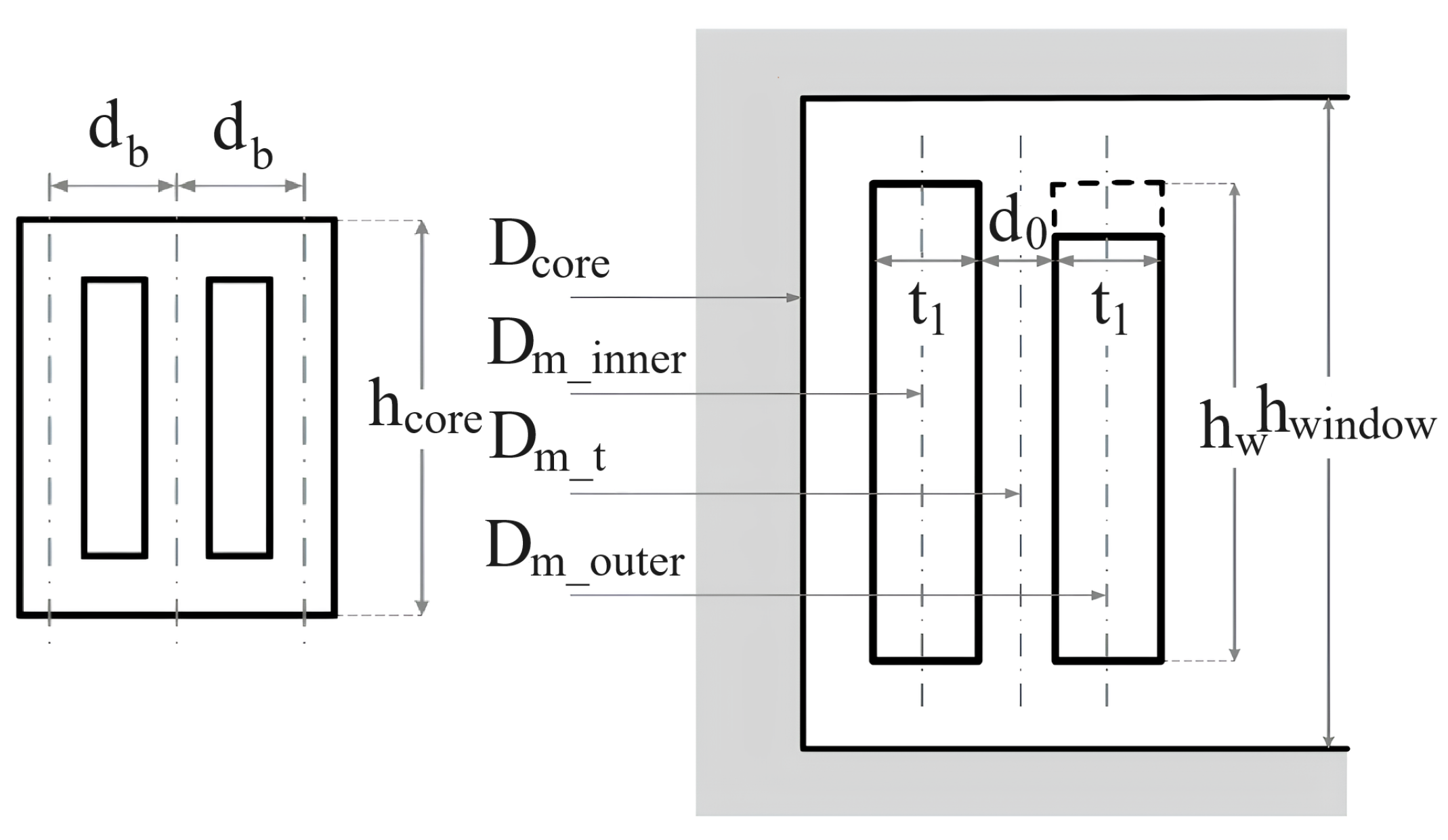
The present work focuses on the central phase of a three-phase transformer prototype, the same analyzed in the previous papers of the authors [1,11,23]. It includes concentric coils with a 5% tap at the head of the external winding. The active part constructive dimensions are illustrated in Figure 7, with the tap indicated by a dashed line at the upper head of the outer winding, and detailed in Table 1.
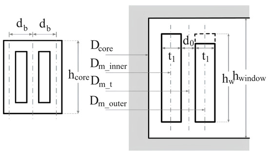
Figure 7.
Active part constructive characteristics.

Table 1.
Constructive and operational characteristics of the Waters prototype [24].
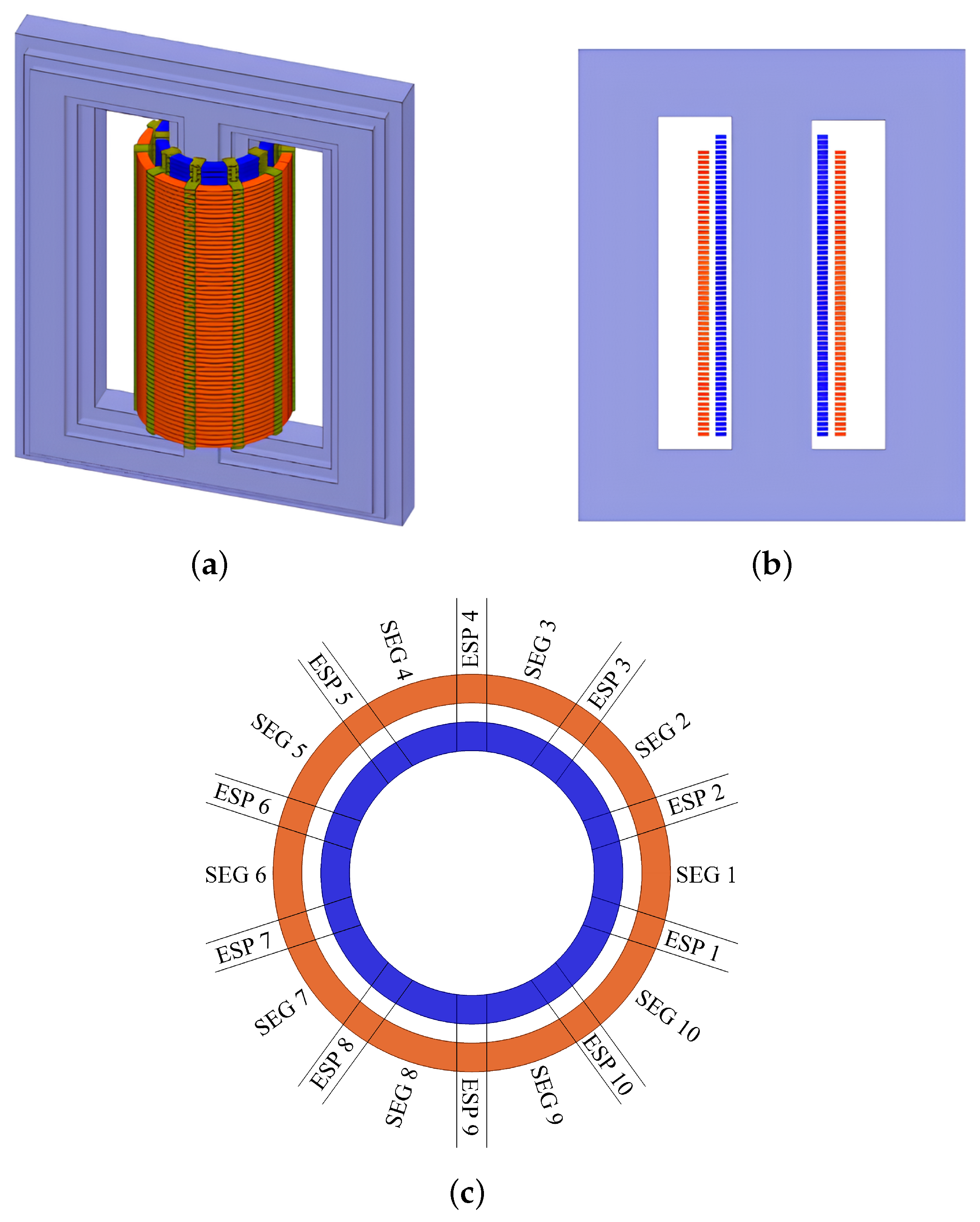
The prototype was simulated in ANSYS Electronics Desktop© software using a 3D simulation, which can be seen in Figure 8. The electromagnetic simulation was carried out in a static regime, examining the actual forces during the short-circuit peak. The modeled transformer consisted of 60 discs in the LV and 57 discs in the HV, indicating a 5% tap in the external winding, as shown in Figure 8a,b. Both windings are equipped with 10 axial spacers, resulting in 10 segments of discs in between the spacers, as shown in Figure 8c, where the spacers and segments are called “ESP” and “SEG”, respectively. The analysis of the electromagnetic forces will cover the entire HV winding, while the structural analysis will encompass segments 1 to 3, including spacers 1 to 4, within the HV winding. The 3D structural model used for mechanical analysis is presented in Figure 9.

Figure 8.
Finite element model: (a) Isometric view. (b) Side view. (c) Top view.

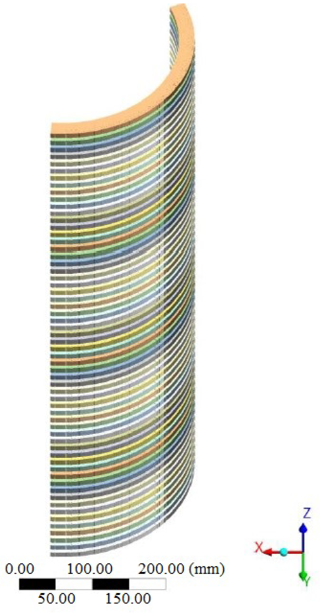
Figure 9.
Structural model for mechanical analysis.
5. Results
The modeling and simulations were carried out using the commercial software ANSYS Workbench©, version 2022 R1, on a computer with 16 GB of RAM and an Intel Core i7 8th generation processor, operating at 2 GHz. The 3D simulations performed in ANSYS Electronics Desktop and Mechanical had an average duration of approximately 4 h. The electromagnetic simulation mesh had a total number of 1,506,511 elements, and the structural simulation involved a total number of 100,092 elements.
Initially, the analytical calculations for radial and axial forces were performed for comparison and verification of the finite element data. Table 2 provides a comparison between the analytical Waters method and the finite element simulation. The maximum difference between the methods was less than 7%, indicating a good precision when using FEM.
Table 2.
Analytical and FEM results for electromagnetic forces.
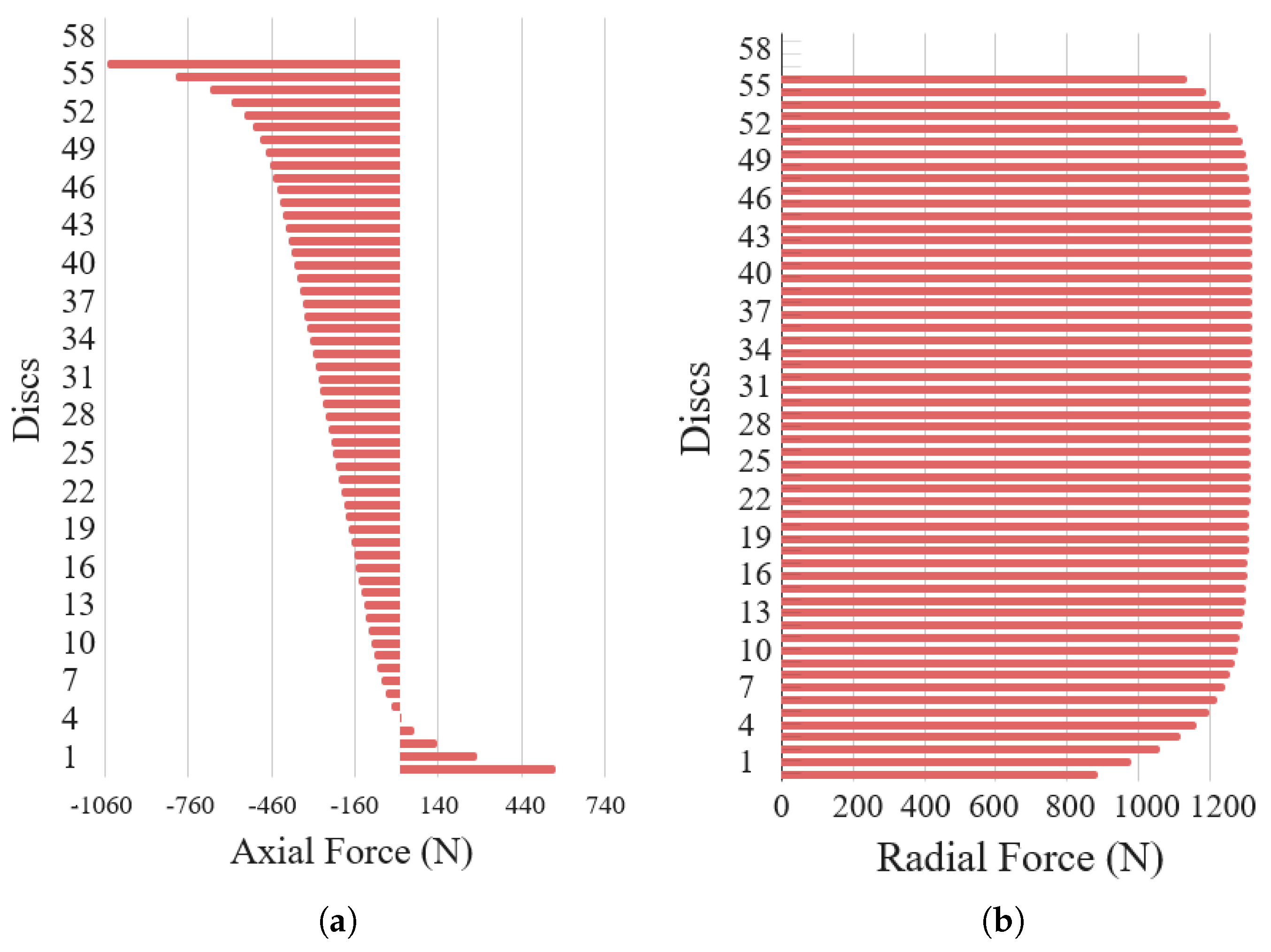
Regarding the distribution of the electromagnetic forces over the discretizations of the windings, segment 1, located below the core window, presents the highest electromagnetic stresses, as seen in Figure 10. In Figure 10a, the axial forces along the HV winding can be observed. The top disc experiences a force of −1.053 kN, and it is evident that the stresses reduce along the lower discs, and experience a reversal in the force direction towards the base of the windings. The behavior of the axial force indicates that the outer winding is subjected to a downwards pressure, compressing the structure towards the base of the transformer.

Figure 10.
Electromagnetic forces in a high-voltage winding: (a) axial forces (N), (b) radial forces (N).
In Figure 10b, it can be seen that HV winding supports positive outreach stresses, with forces that are nearly uniform toward the center of the windings and a decrease in magnitude at the extremities, where there is a curvature in the magnetic flux. Disc 43, located just above the center of the winding, presented the highest stress, reaching 1.318 kN.
For the structural analysis, the mechanical stresses were calculated for the disc that experienced the highest electromagnetic stresses, with disc 57 for axial forces and disc 43 for radial forces. The geometric model for the simulation encompassed only the external winding, from spacer 1 to spacer 4. Consequently, the simulations were conducted in the ANSYS Mechanical—Static Structural model. Table 3 presents a comparison between the analytical solution presented in Section 4 and the computational simulations, indicating an error lower than 3%, which demonstrates the accuracy of the numerical calculations.
Table 3.
Analytical and FEM results for mechanical stresses in the center of the segment.
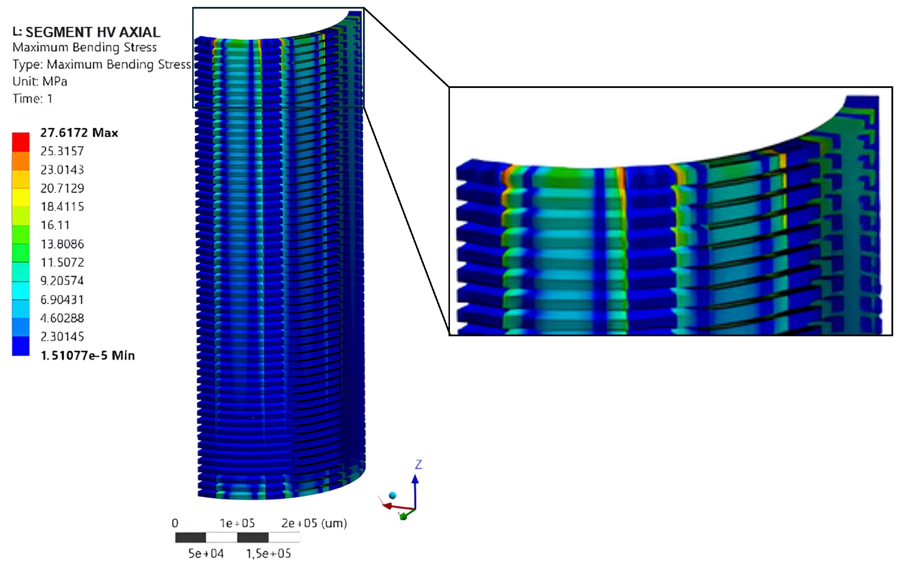
Figure 11 illustrates the axial stress distribution along a cross-section of the winding, with an average stress of 1.91 MPa, predominantly in the disc nearest to the head where the highest electromagnetic forces were encountered. Additionally, it is noticeable that the highest stress magnitudes were observed in the disc segments situated between the radial spacers.
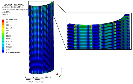
Figure 11.
Axial stress distribution along the segment.
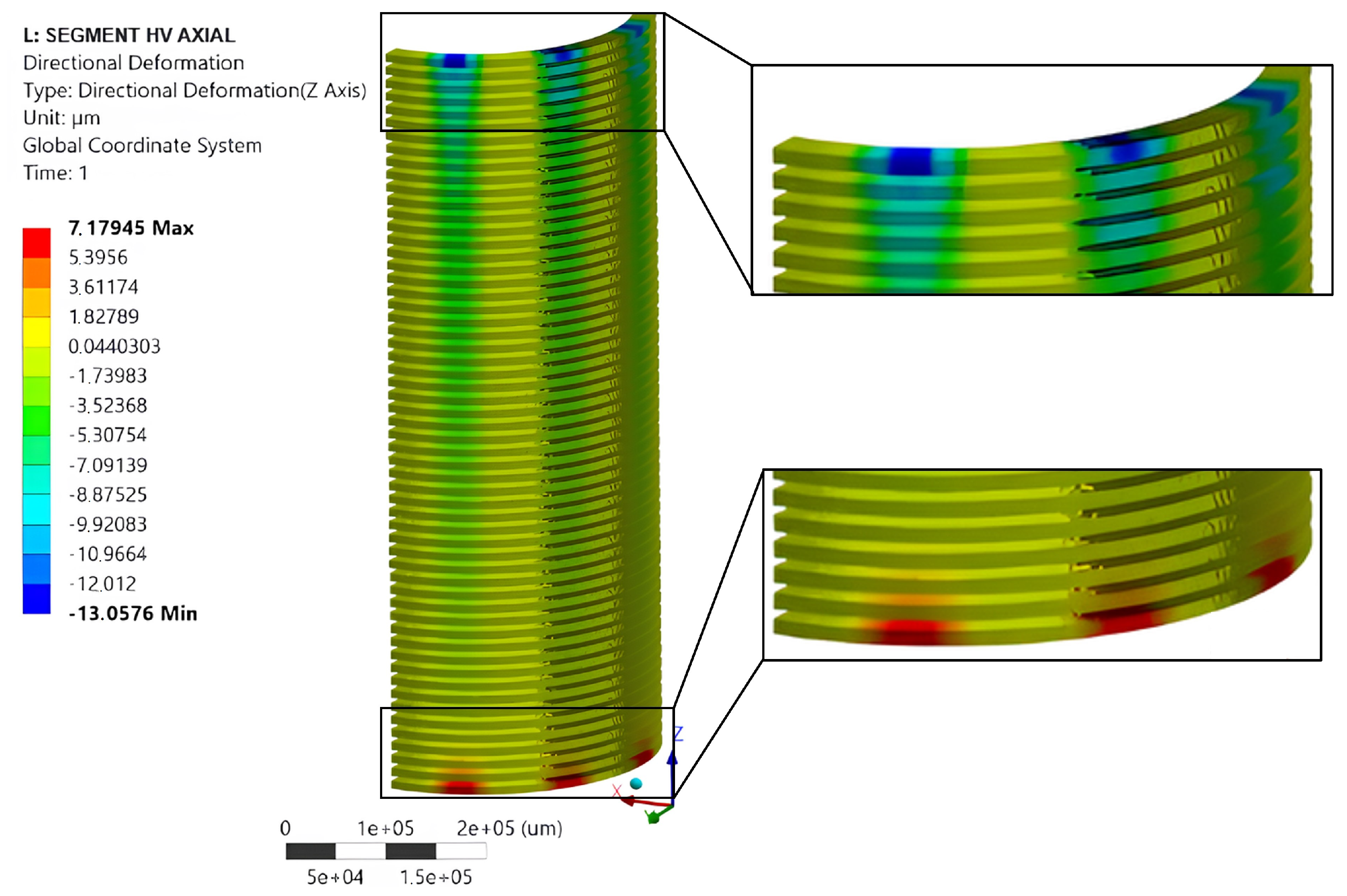
Figure 12 shows the disc strains, where the conductors were made of copper and reached a temperature of 115 °C. The most significant displacements were observed at the extremities of the windings, with a maximum displacement of 13.05 m in disc 57. In Figure 13, a comparison of the axial displacement distribution across the 57 discs in segment 1 is presented. To facilitate the analysis, it was assumed that all turns in the windings had the same dimensions for both copper and aluminum. Consequently, the highest displacement was observed in the aluminum winding, given that its Young’s Modulus was smaller than that of copper. In the graph, it is evident that disc 57 reached a displacement of 22.09 m, representing an increase of 9.04 m compared with the displacement observed for copper.

Figure 12.
Axial displacement distribution along the segment.
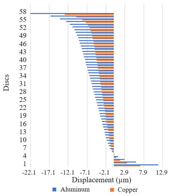
Figure 13.
Axial displacement comparison considering copper and aluminum.
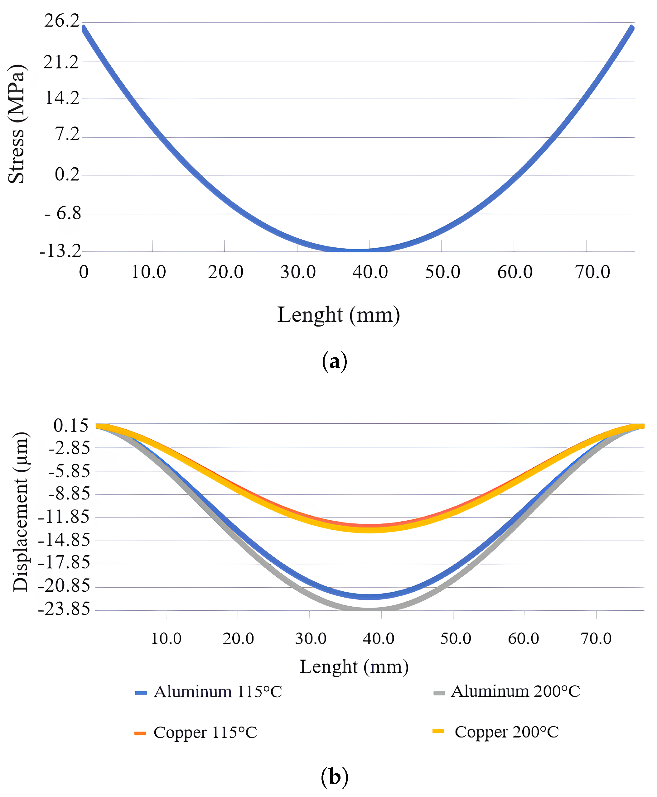
Subsequently, a more detailed analysis was conducted on segment 1 of disc 57 in the external winding. In Figure 14a, the stress distribution along the disc segment is illustrated. Stress reached 28 MPa at the extremities of the segment, where the disc was firmly held between the spacers and was not deformable. However, this state could potentially lead to a process of cracking of the material. In the center of the segment, the point of greatest displacement, the stress was −13.77 MPa.
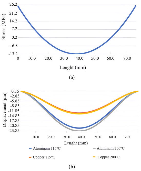
Figure 14.
Analysis of segment 1 of disc 57: (a) Axial Stress. (b) Axial Displacement.
Figure 14b shows the segment displacement using copper and aluminum as the winding conductor materials at temperatures of 115 °C and 200 °C—temperatures that the winding could reach during fault transients. The displacement with copper increased by 0.46 m at 200 °C, while with aluminum, the increase was 1.75 m.
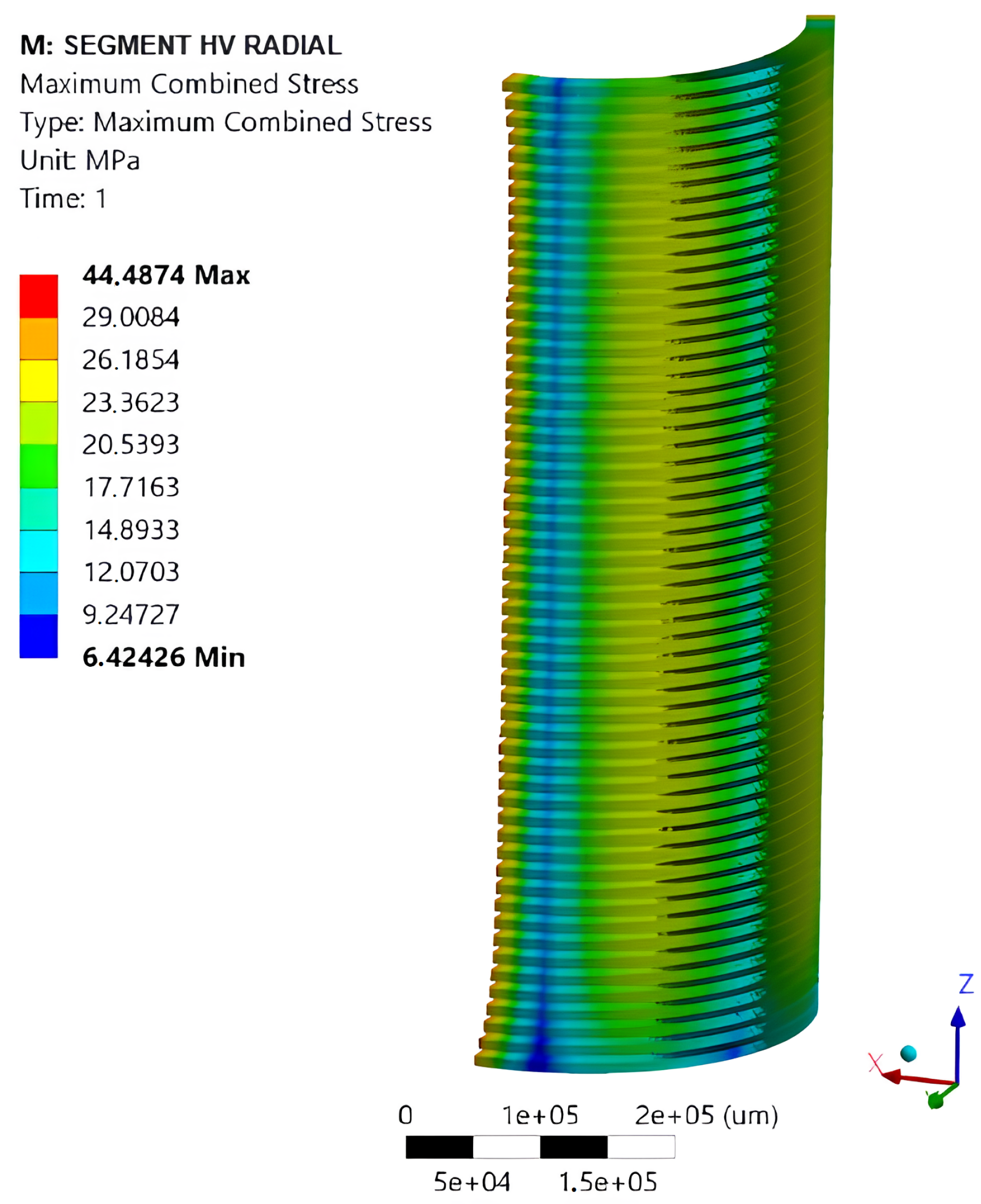
In the radial tension simulation, the average tension was 20.29 MPa, and its distribution can be seen in Figure 15. The highest stresses were located in segments 1 and 2 and spacer 2, with a magnitude of approximate 26 MPa. The high magnitude in comparison with the axial simulation was due to the fact that the external winding did not have a spacer to restrain the expansion movement caused by the stresses.
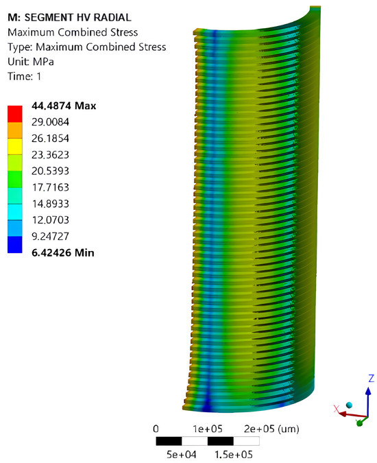
Figure 15.
Radial stress distribution along the segment.
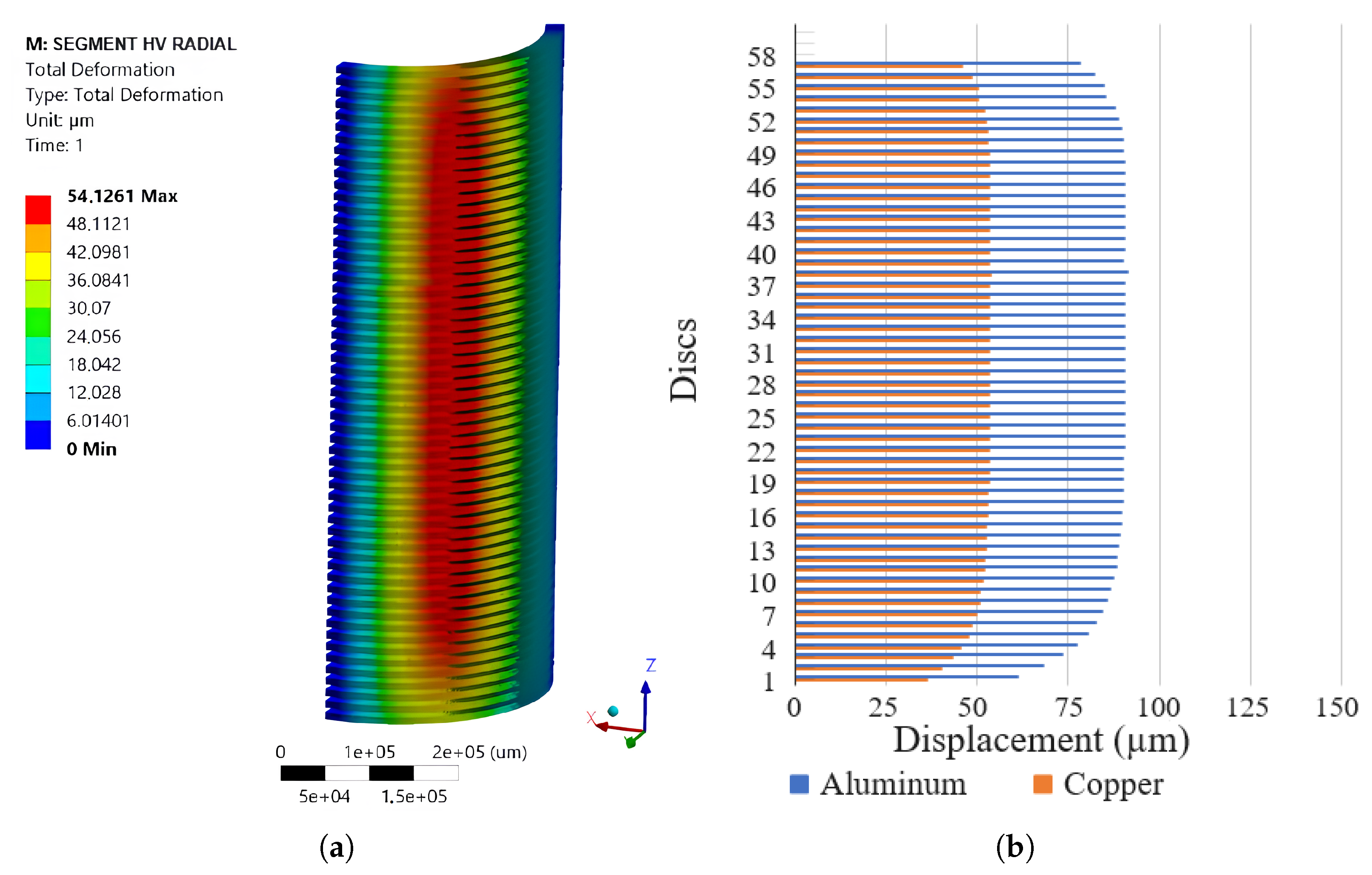
The greatest radial displacement was observed at the points with the highest stresses, reaching 54 m, as depicted in Figure 16a. In Figure 16b the comparison between using copper and aluminum as conductors in temperature 115 °C is presented. The maximum displacement was 90 m for aluminum, which is 36 m higher than that using a copper conductor.

Figure 16.
Radial displacement: (a) Displacement distribution along the segment. (b) Comparison of the resulting copper and aluminum displacements.
6. Conclusions
This study conducted electromagnetic–structural simulations of a transformer with concentric windings, with a tap at the head, focusing on assessing deformation in the HV winding. Conductor displacement can potentially damage the insulation and lead to internal short-circuits in the transformer. It can also result in loosening of the spacers, which must be secured to prevent winding inclination or tilting, ultimately reducing the mechanical stability of the structure.
The FEM methodology has the accuracy verified when compared with the analytical results, reaching errors below 7%, demonstrating its effectiveness. One of the features of the computational simulations is the visual analysis, revealing the areas most affected by the electromechanical forces and the estimation of displacements using the copper and aluminum materials. Aluminum, with its lower modulus of elasticity compared with copper, presented larger displacements. Through the analysis with different temperatures, it was verified that aluminum is more influenced by the temperature increase.
The better understanding of the electromagnetic forces and mechanical stresses distributions along the winding allows for an optimized design. Knowing the points of the lower and greater stresses values, the number, dimensions, and position of the spacers can be selected appropriately, in addition to reducing the costs of an oversized project. Also, these results can be coupled to a thermal analysis, making it possible to verify the impacts of the mechanical design in the thermal one, optimizing the spacers choices.
The obtained results show that future studies can be conducted in order to evolve in this area. The fatigue analysis is important to be verified, considering how factors such as the number of short-circuits, duration, and intensity can impact the conductors deformation and lifespan of transformers.
Author Contributions
Conceptualization, R.G.C., B.L.L., L.H.M., H.C.F., C.H.C. and R.C.; methodology, R.G.C., B.L.L., L.H.M., R.C.B., T.d.S., T.B.M. and V.C.B.; software, R.G.C., B.L.L., R.C.B. and T.d.S.; validation, R.G.C., B.L.L. and T.d.S.; formal analysis, T.d.S., T.B.M. and V.C.B.; investigation, R.G.C., B.L.L., L.H.M., R.C.B., T.d.S., T.B.M. and V.C.B.; resources, H.C.F., C.H.C., R.C., T.B.M. and V.C.B.; data curation, R.G.C., B.L.L., L.H.M., R.C.B. and T.d.S.; writing—original draft preparation, R.G.C., B.L.L., L.H.M., H.C.F., C.H.C., R.C., R.C.B., T.d.S. and V.C.B.; writing—review and editing, R.G.C., B.L.L., L.H.M., R.C.B., T.d.S. and V.C.B.; supervision, R.C.B., T.B.M. and V.C.B.; project administration, H.C.F., C.H.C., R.C., T.B.M. and V.C.B.; funding acquisition, T.B.M. and V.C.B. All authors have read and agreed to the published version of the manuscript.
Funding
This work was supported in part by the Coordenação de Aperfeiçoamento de Pessoal de Nível Superior (CAPES/PROEX), Brazil, under Finance Code 001; and in part by the Companhia Paulista de Energia CPFL under Project PD-05785-2119/2021.
Data Availability Statement
The data is unavailable due to privacy restrictions.
Acknowledgments
This study was financed in part by the Coordenação de Aperfeiçoamento de Pessoal de Nível Superior—Brasil (CAPES)—Finance Code 001, and developed with support of CNPq, National Council for Scientific and Technological Development—Brazil (405054/2022-0). The authors thank the Electric Sector Research and Development Program, through the project PD-05785-2119/2021: “Computer tool of the study, analysis and diagnosis of very fast transients in power transformers”, regulated by the National Electric Energy Agency—ANEEL, in partnership with CPFL Transmission. The authors also thank the technical and financial support of the Federal University of Santa Maria (UFSM), Electrical Engineering Post Graduate Program (PPGEE), National Institute of Science and Technology (INCT)—Distributed Generation of UFSM and Smart Grids Institute of UFSM.
Conflicts of Interest
Author H.C.F., C.H.C. and R.C. was employed by the company Companhia Paulista de Energia. The remaining authors declare that the research was conducted in the absence of any commercial or financial relationships that could be construed as a potential conflict of interest.
References
- Medeiros, L.H.; Maschio, G.; Oliveira, M.M.; Kaminski, A.M., Jr.; Bueno, D.M.; Bender, V.C.; Marchesan, T.B. Finite element analysis for calculation of total and distributed electromagnetic forces on power transformers windings arrangements. Electr. Eng. 2024, 106, 931–940. [Google Scholar] [CrossRef]
- Ashkezari, A.D.; Ma, H.; Saha, T.K.; Ekanayake, C. Application of fuzzy support vector machine for determining the health index of the insulation system of in-service power transformers. IEEE Trans. Dielectr. Electr. Insul. 2013, 20, 965–973. [Google Scholar] [CrossRef]
- Jahromi, A.; Piercy, R.; Cress, S.; Service, J.; Fan, W. An approach to power transformer asset management using health index. IEEE Electr. Insul. Mag. 2009, 25, 20–34. [Google Scholar] [CrossRef]
- Luiz, M.C. Avaliação dos Impactos da Geração Distribuída para Proteção do Sistema Elétrico. Master’s Thesis, UFMG, Belo Horizonte, Brazil, 2012. [Google Scholar]
- Group du Travail. 12.05 Cigre. Enquête Internationale sur les Défaillances en Service des Transformateurs de Grande Puissance. Electra 1983, 88, 21–48. [Google Scholar]
- Kulkarni, S.V.; Khaparde, S.A. Transformer Engineering: Design and Practice. In Transformer Engineering: Design and Practice; CRC Press: Boca Raton, FL, USA, 2004. [Google Scholar]
- Araujo, J.; Costa, E.; Andrade, A.; Germano, T.; Ferreira, T. Methodology to Evaluate the Electromechanical Forces on Conductive Materials in Transformers Windings using the Von Mises and Fatigue Criteria. IEEE Trans. Power Deliv. 2016, 31, 2206–2214. [Google Scholar] [CrossRef]
- Barros, R.; Costa, E.; Araujo, J.; Andrade, F.; Ferreira, T. Contribution of inrush current to mechanical failure of power transformers windings. Inst. Eng. Technol. 2019, 4, 300–307. [Google Scholar] [CrossRef]
- Zhang, H.; Yang, B.; Xu, W.; Wang, S.; Wang, G.; Huangfu, Y.; Zhang, J. Dynamic Deformation Analysis of Power Transformer Windings in Short-Circuit Fault by FEM. IEEE Trans. Appl. Supercond. 2014, 24, 1–4. [Google Scholar] [CrossRef]
- Silva, N.H.G. Avaliação da Operação da Proteção Diferencial em Transformadores de Potência; Centro Federal de Educação Tecnológica de Minas Gerais: Belo Horizonte, Brazil, 2015. [Google Scholar]
- Medeiros, L.H.; Maschio, G.; Oliveira, M.M.; Kaminski, A.M.; Bueno, D.M.; Bender, V.C.; Marchesan, T.B. Finite Element Analysis applied to Electromagnetic Forces calculation on Power Transformers. In Proceedings of the SEPOC, Online, 15 May 2021. [Google Scholar]
- Li, Y.; Xu, Q.; Lu, Y. Electromagnetic Force Analysis of a Power Transformer Under the Short-Circuit Condition. IEEE Trans. Appl. Supercond. 2021, 31, 1–3. [Google Scholar] [CrossRef]
- Bakshi, A.; Kulkarni, S.V. Analysis of Buckling Strength of Inner Windings in Transformers Under Radial Short-Circuit Forces. IEEE Trans. Power Deliv. 2013, 29, 241–245. [Google Scholar] [CrossRef]
- Zhang, B.; Yan, N.; Ma, S.; Wang, H. Buckling Strength Analysis of Transformer Windings Based on Electromagnetic Thermal Structural Coupling Method. IEEE Trans. Appl. Supercond. 2019, 29, 1–4. [Google Scholar] [CrossRef]
- Geißler, D.; Leibfried, T. Short-Circuit Strength of Power Transformer Windings-Verification of Tests by a Finite Element Analysis-Based Model. IEEE Trans. Power Deliv. 2017, 32, 1705–1712. [Google Scholar]
- Ho, S.L.; Li, Y.; Wong, H.C.; Wang, S.H.; Tang, R.Y. Numerical simulation of transient force and eddy current loss in a 720-MVA power transformer. IEEE Trans. Magn. 2004, 40, 687–690. [Google Scholar] [CrossRef]
- Zhang, C.; Ge, W.; Xie, Y.; Li, Y. Comprehensive Analysis of Winding Electromagnetic Force and Deformation During No-Load Closing and Short-Circuiting of Power Transformers. IEEE Access 2021, 9, 73335–73345. [Google Scholar] [CrossRef]
- Wang, S.; Wang, S.; Zhang, N.; Yuan, D.; Qiu, H. Calculation and Analysis of Mechanical Characteristics of Transformer Windings Under Short-Circuit Condition. IEEE Trans. Magn. 2019, 55, 1–4. [Google Scholar] [CrossRef]
- Fonseca, W.S.; Lima, D.S.; Lima, A.K.F.; Nunes, M.V.A.; Bezerra, U.H.; Soeiro, N.S. Analysis of Structural Behavior of Transformer’s Winding Under Inrush Current Conditions. IEEE Trans. Ind. Appl. 2018, 54, 2285–2294. [Google Scholar] [CrossRef]
- Lee, J.Y.; Ahn, H.M.; Kim, J.K.; Oh, Y.H.; Hahn, S.C. Finite element analysis of short circuit electromagnetic force in power transformer. Int. Conf. Electr. Mach. Syst. 2009, 47, 1267–1272. [Google Scholar]
- Guimarães, R.; Delaiba, A.C.; Oliveira, J.C.; Saraiva, E.; Rosentino, A.J.J.P. Electromechanical Forces in Transformers Caused by Inrush Currents: An Analytical, Numerical and Experimental Approach. J. Control Autom. Electr. Syst. 2013, 24, 863–872. [Google Scholar] [CrossRef]
- Ahn, H.; Oh, Y.; Kim, J.; Song, J.; Hahn, S. Experimental Verification and Finite Element Analysis of Short-Circuit Electromagnetic Force for Dry-Type Transformer. IEEE Trans. Magn. 2012, 48, 819–822. [Google Scholar] [CrossRef]
- Cornelius, R.G.; Lenhard, B.; Medeiros, H.; Bender, V.C.; Marchesan, T.B.; Carraro, R. Electromagnetic Forces and Mechanical Stresses in Power Transformers: An Analysis Based on Computer Aided Engineering. In Proceedings of the SEPOC, Online, 12 November 2022. [Google Scholar]
- Waters, M. The Short-Circuit Strength of Power Transformers; Macdonald & Co.: London, UK, 1966. [Google Scholar]
- Zhang, H.; Wang, S.; Wang, S. Cumulative Deformation Analysis of Transformer Winding under Short-Circuit Fault Using 3-D FEM. In Proceedings of the IEEE International Conference on Applied Superconductivity and Electromagnetic Devices, Shanghai, China, 20–23 November 2015; pp. 370–371. [Google Scholar]
- IEC 60076-5; Power Transformers—Part 5: Ability to Withstand Short Circuit. International Electrotechnical Commission: Geneva, Switzerland, 2006.


Disclaimer/Publisher’s Note: The statements, opinions and data contained in all publications are solely those of the individual author(s) and contributor(s) and not of MDPI and/or the editor(s). MDPI and/or the editor(s) disclaim responsibility for any injury to people or property resulting from any ideas, methods, instructions or products referred to in the content. |
© 2024 by the authors. Licensee MDPI, Basel, Switzerland. This article is an open access article distributed under the terms and conditions of the Creative Commons Attribution (CC BY) license (https://creativecommons.org/licenses/by/4.0/).