Article

Enhancement of Low Voltage Ride Through (LVRT) Capability of DFIG-Based Wind Turbines with Enhanced Demagnetization Control Model

by
M. Kenan Döşoğlu
1,* and
Muhsin Uğur Doğan
2
1
Faculty of Engineering, Electrical Electronics Engineering Department, Duzce University, Duzce 81620, Turkey
2
Bolu Technical Sciences High School, Department of Electronic and Automation, Bolu Abant Izzet Baysal University, Bolu 14200, Turkey
*
Author to whom correspondence should be addressed.
Energies 2024, 17(16), 4015; https://doi.org/10.3390/en17164015
Submission received: 27 June 2024 / Revised: 30 July 2024 / Accepted: 9 August 2024 / Published: 13 August 2024
(This article belongs to the Section F1: Electrical Power System)

Abstract

:
Since the stator of DFIG-based wind turbines is directly connected to the grid, it is dramatically affected by transient situations that may occur on the grid side. In order to meet grid code requirements, reactive power support must be provided to keep the DFIG connected to the grid during the transient state. To achieve this, Low Voltage Ride Through (LVRT) capability needs to be implemented in the grid-connected DFIG. Depending on the grid code requirements, different control models are used to provide LVRT capability. In this study, the demagnetization control model was developed in DFIG. In addition, the stator dynamic model has also been developed in order to decrease the disturbances that occur due to the stator being directly connected to the machine and to increase the calculation performance within the machine. While natural and forced flux models based on rotor electromotive force were developed in the demagnetization control model in DFIG, the stator electromotive force model was developed to ensure stator dynamics. In the study, it was seen that the demagnetization control model developed for transient situations such as balanced and unbalanced faults gave better results than the traditionally used model. The results obtained were evaluated in detail in terms of stability and oscillations.

1. Introduction

With the rapid increase in the use of wind energy in recent years, renewable energy forms have become the most competitive. Among the different wind energy conversions, the most widely used is DFIG. However, it is very affected by transient stability situations such as balanced and unbalanced faults occurring on the grid side. The reason for this is that the stator windings in DFIG are connected directly to the grid. To eliminate this, LVRT capability must be implemented in DFIG according to grid code requirements. In the literature on the implementation of DFIG’s LVRT capability, different models are developed according to their usage areas [1]. In DFIG, various feed-forward models have been developed to control the Rotor Side Inverter (RSC) circuit in case of faults. When a fault occurs in the system, RSC is effective in compensating the output voltage, limiting the minimum transient rotor current, and obtaining uninterrupted energy [2,3,4]. Positive and negative sequential models have been developed to increase the power value depending on LVRT ability during transient stability in the RSC circuit of DFIG. In addition to positive and negative sequential models, natural sequential models have been developed in various studies to effectively dampen the oscillations that occur after the transient state [5,6]. State estimation models for LVRT capability are being developed in DFIG. It is seen in related studies that the developed model is used effectively to regulate the rotor current and effectively minimize the oscillations that occur in case of a rotor failure [7,8]. Various robust models have been developed in DFIG to obtain smooth power and ensure reactive power control. Electrical and mechanical controls are provided by DFIG, adhering to grid code requirements [9,10]. In DFIG, serial dynamic braking resistor units are developed to eliminate problems such as voltage drop and increased oscillation due to the stator being directly connected to the grid during transient situations. By using these units, LVRT capability is achieved [11,12]. Fault current limiter models in the DC link feeding both the RSC circuit and the Grid Side Inverter (GSC) circuit in DFIG have also been developed in the literature. In addition to compensating the voltage and increasing the oscillation, it effectively suppresses the inrush current [13,14]. Faults in DFIG cause not only many negative electrical effects but also various mechanical problems. For this reason, different hybrid LVRT models are also preferred in the literature [15,16]. Nonlinear control methods are widely preferred to ensure LVRT capability in DFIG. Disturbance observer-based sliding mode control and backstepping models are being developed in simulation studies to reduce the computational load and minimize chattering effects [17,18,19]. In order to ensure the LVRT capability in DFIG in symmetric and asymmetric faults according to grid code requirements, the rotor current and voltage must be controlled within certain limits. The goal is to achieve this within a certain orbit. Therefore, active disturbance rejection control effectively provides LVRT capability [20,21]. Another important approach used to ensure LVRT capability in DFIG is demagnetization control [22,23]. Especially in DFIG, problems are brought about due to magnetism. The use of demagnetization control effectively eliminates magnetism problems. However, this control model may not be sufficient for parameter changes in transient stability situations. Therefore, an advanced demagnetization control for DFIG that will not be affected by system parameter changes is the goal of this study. Comparisons from some literature studies are shown in Table 1.
The contribution of this study to the literature is shown in detail as follows:
(1)
In DFIG, a demagnetization control model has been developed to limit parameter changes within a certain trajectory in stability situations. Moreover, the rotor electromotive force model has been developed mathematically to dampen the oscillations in the system more quickly.
(2)
Small time steps are required for numerical operations in the simulation study because of the integration of incremental calculation results. Therefore, the stator electromotive force model was developed mathematically to facilitate calculations.
(3)
The electromotive force models developed in both stator and rotor circuits are adapted to work in a coordinated manner to provide the best system control in balanced and unbalanced faults.
(4)
This study aims to support the demagnetization control model by developing a forced flux model in order to better control the dynamic process in providing LVRT capability in DFIG according to grid code requirements.
In this study, the stator dynamic modeling in DFIG is included in Section 2, while the demagnetization control model developed in DFIG is included in Section 3. Section 4 and Section 5, the simulation study and the results from the simulation study, are given in detail, respectively. In the last section, the conclusion is discussed.

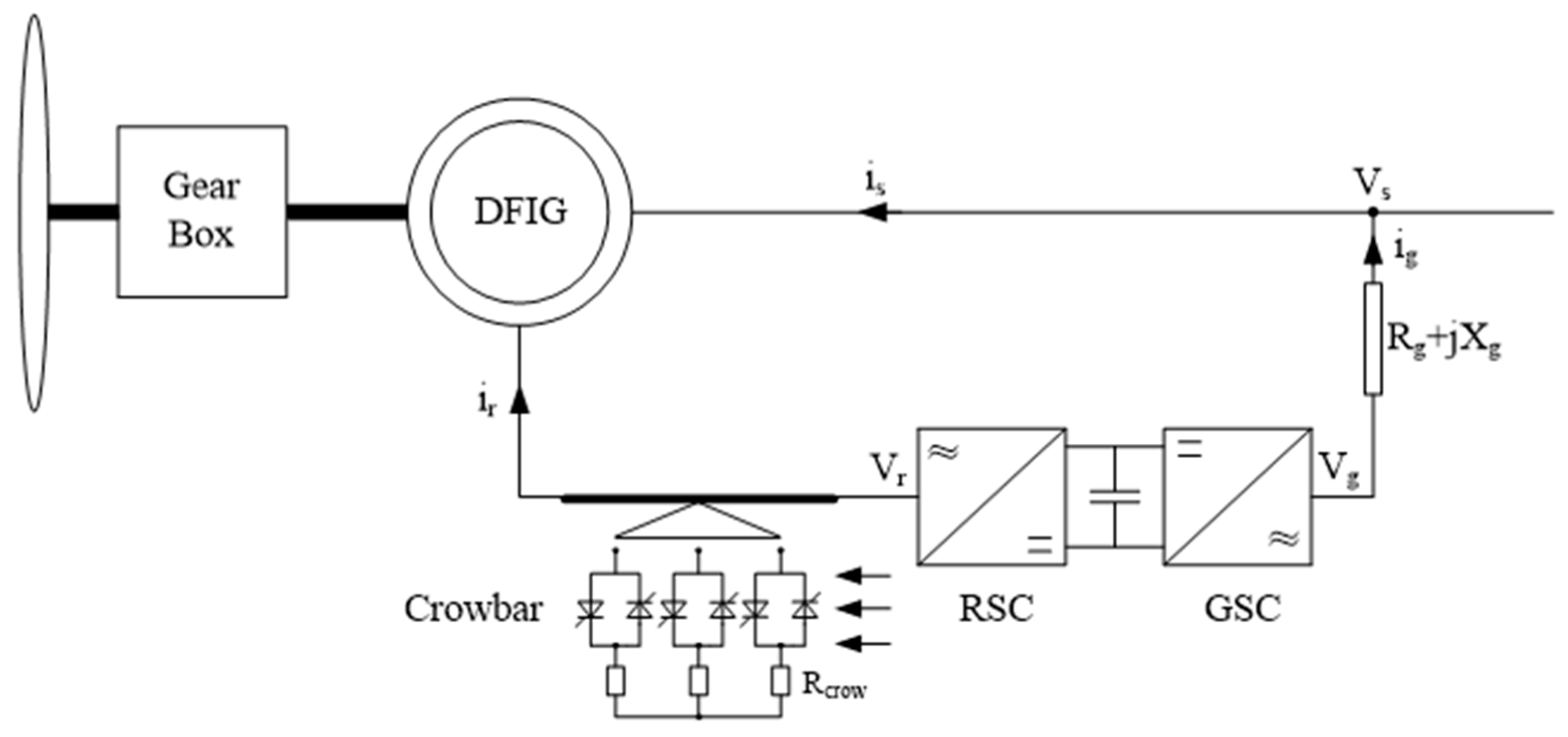
2. Stator Dynamic Model in DFIG

DFIG-based wind turbines are used as wound rotor induction generators, where the rotor winding is fed through back-to-back connected variable frequency voltage source converters. The circuit model of DFIG is given in Figure 1.
In DFIG, the converter system separates the electrical frequency in the power system from the rotor mechanical frequency. In this way, it enables the wind turbine to operate at variable speeds. For this, back-to-back (RSC and GSC) converters are used, as seen in Figure 1. The crowbar unit used in DFIG is a piece of equipment that protects the power converter from overcurrent–voltage situations and facilitates the system to recover quickly from a fault. The crowbar unit is activated when an overcurrent–voltage condition is observed and operates as soon as possible to provide power output to the grid. However, this needs to be timed very well. They are quickly deactivated when excessive current–voltage ends in the system. In realizing the ease of calculation in DFIG, p.u. calculation is preferred. The d–q axis stator–rotor voltage and flux expressions in DFIG modeling are shown between Equations (1) and (8).
v d s = R s i d s + w s λ q s + d d t λ d s
v q s = R s i q s w s λ d s + d d t λ q s
v d r = R r i d r + s w s λ q r + d d t λ d r
v q r = R r i q r + s w s λ d r + d d t λ q r
λ d s = ( L s + L m ) i d s + L m i d r
λ q s = ( L s + L m ) i q s + L m i q r
λ d r = ( L r + L m ) i d r + L m i d s
λ q r = ( L r + L m ) i q r + L m i q s
A stator dynamic model is being developed to provide ease of calculation and further accelerate the dynamic process of simulation study in the DFIG-based wind turbine. In these calculations, the stator electromotive force model is designed. In this study, a standard method of reducing the order of the DFIG model by neglecting the stator flux change rate is considered. This method is called stator dynamic modeling. In this model, unlike the traditionally used model, the expressions electromotive force, transient reactance, and open time constant are used [24,25,26]. These expressions are shown broadly in the equations. The expressions used for the stator electromotive force model developed for stator dynamic modeling are shown between Equations (9) and (12).
v d s = R s i d s X i q s + e d s
v q s = R s i q s + X i d s e q s
d e d s d t = 1 T 0 [ e d s ( X X ) × I q s ] + s × w s × e q s w s × L m L m + L s × v d r
d e q s d t = 1 T 0 [ e q s + ( X X ) × I d s ] s × w s × e d s + w s × L m L m + L s × v q r
The transient reactance (X′) and transient open time constant (T0) equations used in the stator dynamic model are shown between Equations (13) and (14).
X = w s ( ( L m + L s ) L m 2 L m + L r )
T 0 = L r + L m R r
where vds, vdr, vqs, and vqr are the d and q axis voltages of the stator and rotor; ids, idr, iqs, and iqr are the d and q axis of currents of the stator and rotor; λds, λqs, λdr, and λqr are the d and q axis magnetic fluxes of the stator and rotor; eds and eqs are the d axis and q axis source voltages of the stator; ws is the angular speed of the stator; s is the slip; Rs and Rr are the resistance of the stator and rotor; X is the stator reactance; Ls and Lr are the inductance of the stator and rotor; Lm is the magnetic inductance.

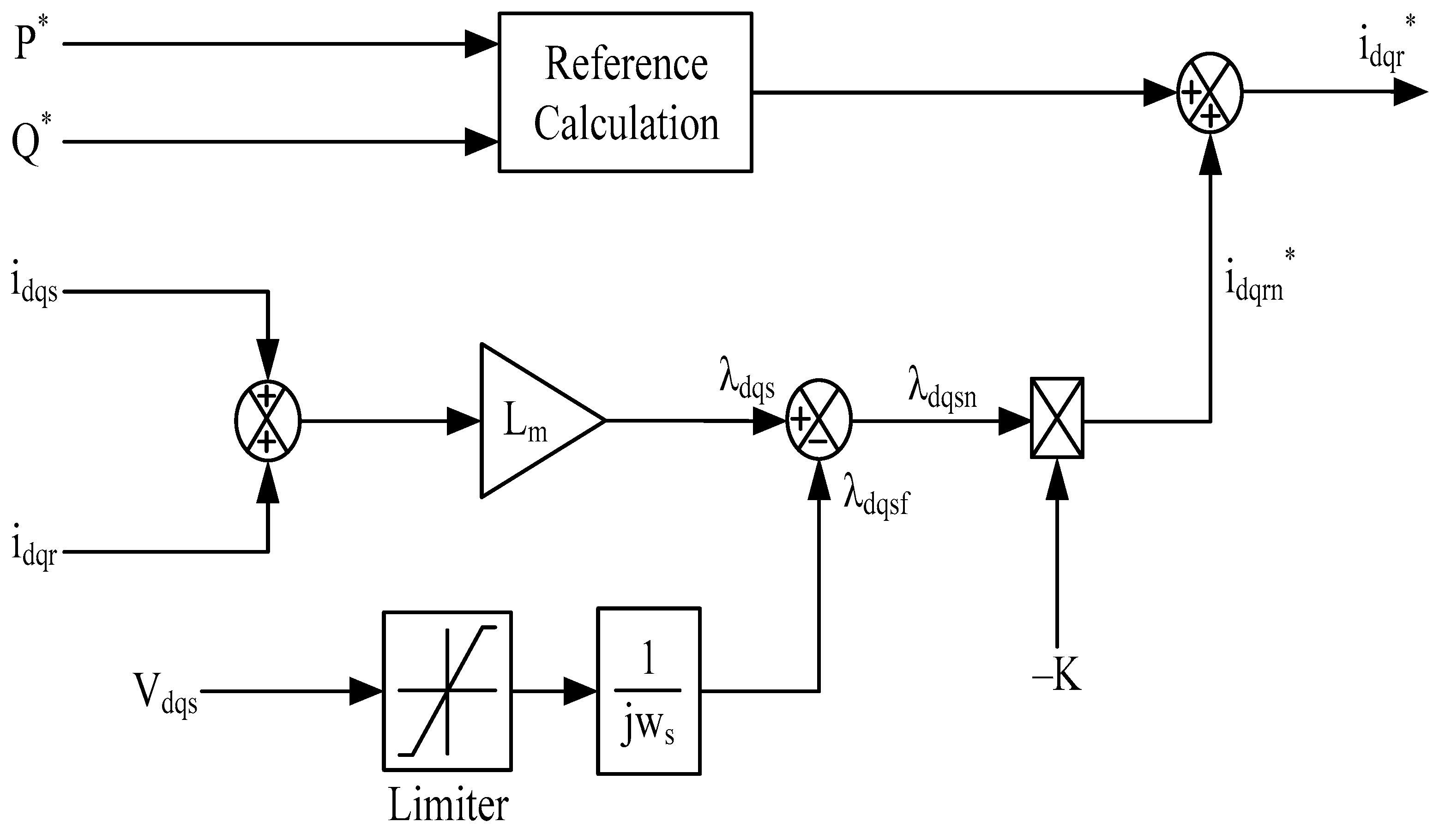
3. Enhanced Demagnetization Control (EDC) Model in DFIG
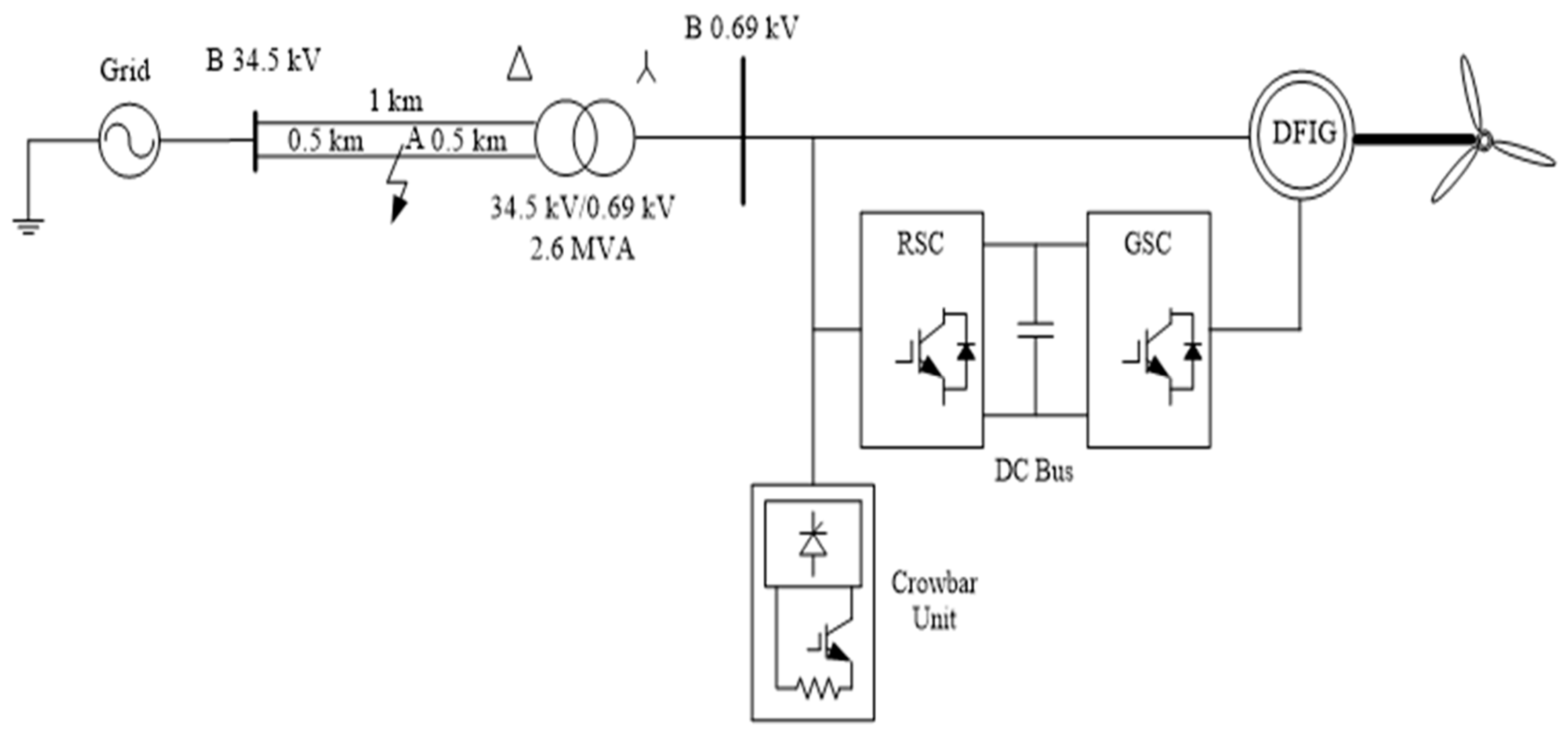
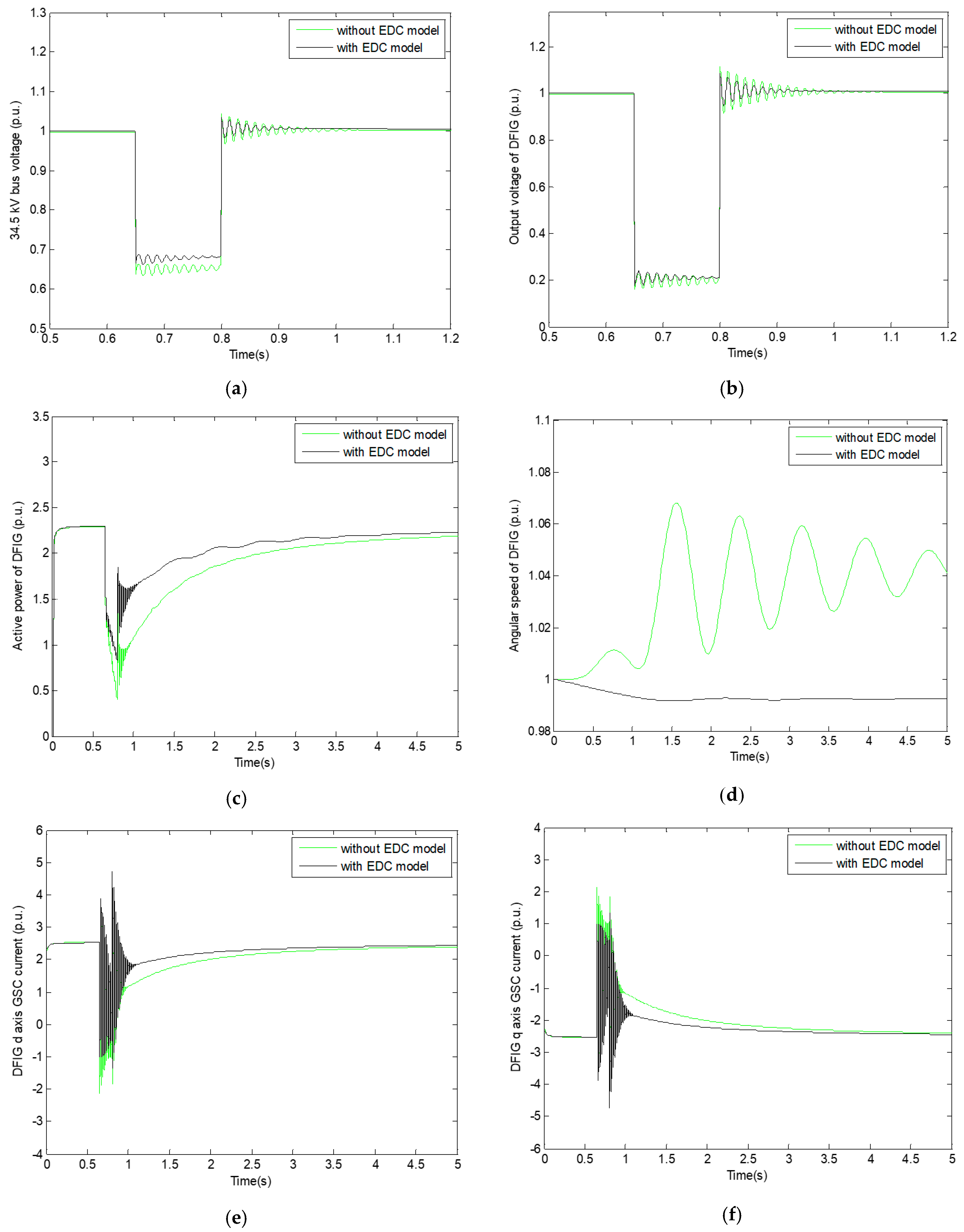
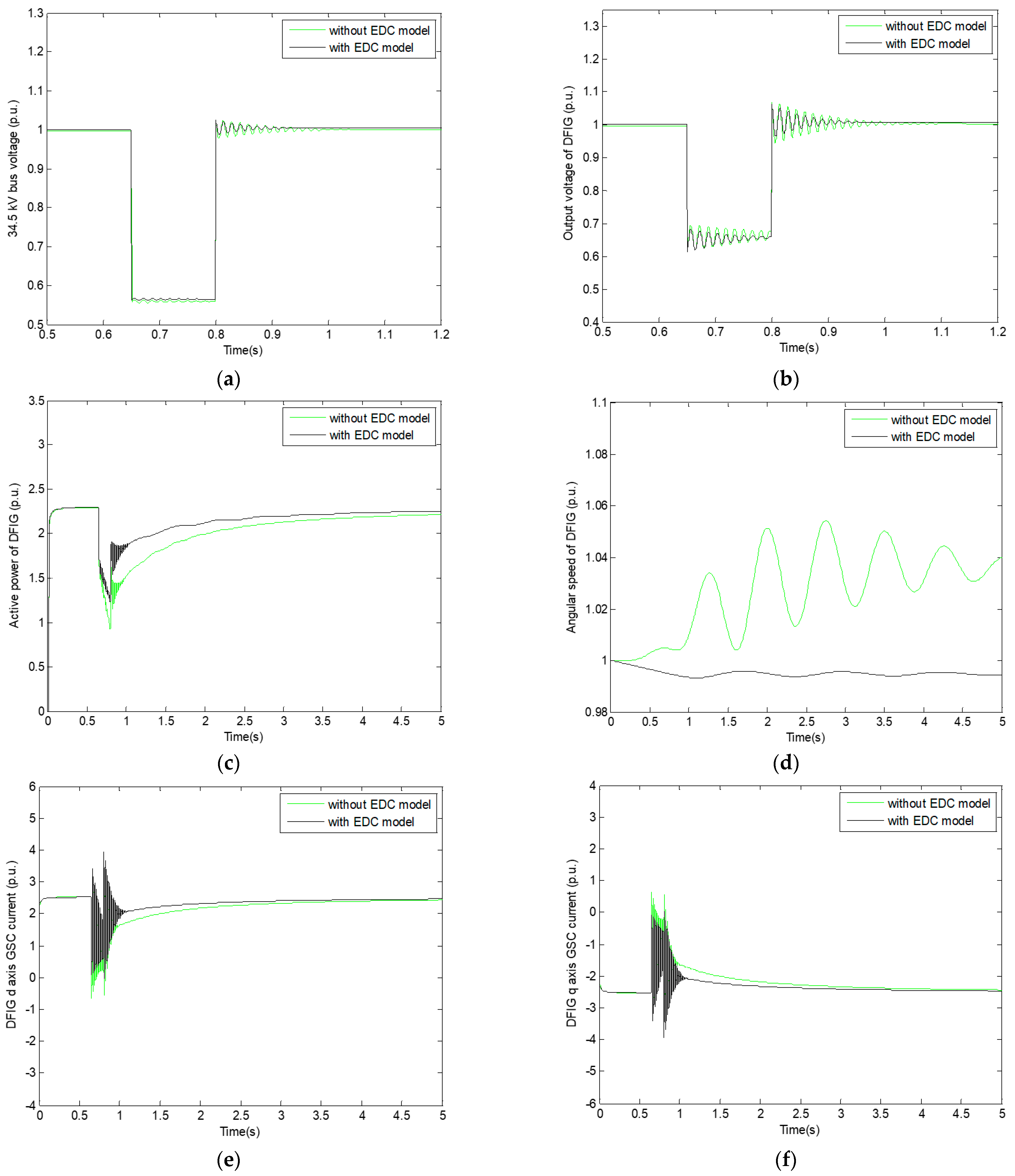
In the demagnetization control model, the operating state of the DFIG during steady and transient states is taken into account. The d–q axis rotor voltage expression in the demagnetization control model is shown in Equation (15).
v d q r = ( R r + ( 1 L m 2 / L s L r ) L r d d t ) i d q r
Equation (15) gives the voltage drop expression in the rotor impedance. Since stator dynamic modeling is used in this study, stator flux derivatization is neglected. To understand the operation of DFIG, the d–q axis stator voltage expression at t = t0 for the voltage drop rate (p) is shown in Equation (16).
v d q s = { V s e j w s t ( t < t 0 ) ( 1 p ) V s e j w s t ( t t 0 )
In steady-state operation (t < 0), the stator d–q axis flux calculation is shown in Equation (17).
λ d q s = V s j w s e j w s t
It can be seen that the stator flux is calculated simultaneously at constant amplitude and angular frequency. As can be seen from the rotor windings, the stator flux can also be calculated depending on the slip frequency. The rotor electromotive force expression depending on slip can be calculated as seen in Equation (18).
e d q r = s L m L s V s e j s w s t
The magnitude of the induced rotor electromotive force model changes proportionally depending on the slip. Therefore, the rotor electromotive force value induced in steady-state operation is small. In the event of a fault that causes a voltage drop of p at the stator output at t = 0, the stator flux does not change. Therefore, in the case of transient stability, natural and forced flux models are developed so that the stator flux can take different values in the transient situation. The derivative expression of the stator flux using the stator dynamic model is shown in Equation (19).
0 = v d q s R s L s λ d q s + L m L s R s i d q r
Using stator dynamic modeling, natural ( e d q r n ) and forced ( e d q r f ) flux equations are shown in Equations (20) and (21).
λ d q s n = p V s j w s e j w s t 0 e ( t t 0 ) / τ
λ d q s f = ( 1 p ) V s j w s e j w s t
where τ represents the natural flux coefficient in the sudden voltage drop. This coefficient can be used continuously in the case of t = t0. Natural and forced flux expressions are expressed as a total, as shown in Equation (22).
λ d q s = p V s j w s e j w s t 0 e ( t t 0 ) / τ + ( 1 p ) V s j w s e j w s t
While the d–q axis natural and forced flux models used in Equations (20) and (21) can be expressed as a total, similarly, the rotor d–q axis natural and forced electromotive force model can also be expressed as a total. Using the stator dynamic model, rotor d–q axis natural and forced electromotive force equations and their total expression are shown between Equations (23) and (25).
e d q r n = ( 1 s ) L m L s p V s e j w s t 0 e ( t t 0 ) / τ e j w s t
e d q r f = s L m L s ( 1 p ) V s e j s w s t
e d q r = ( 1 s ) L m L s p V s e j w s t 0 e ( t t 0 ) / τ e j w s t + s L m L s ( 1 p ) V s e j s w s t
While the forced rotor electromotive force ( e d q r f ) is proportional to s, the natural rotor electromotive force ( e d q r n ) is proportional to (1-s). In the natural rotor electromotive force model, the amplitude is small [27]. However, the amplitude value is higher in the forced rotor electromotive force model. In addition, while the natural rotor electromotive force is proportional to the voltage drop, the forced rotor electromotive force has a higher effect on the rotor windings when there are severe voltage drops.
In demagnetization control, the natural flux decomposes after a certain value. In other words, the natural flux induces voltage by reaching a certain value with the time constant that can be used in the stator dynamic model. However, this is not enough. Therefore, it is recommended that natural flux dynamic modeling be developed in demagnetization control. The equation expressing natural flux dynamic modeling is shown in Equation (26).
d λ s n d t = R s L s λ d q s n + L m L s R s i d q r
As seen in Equation (26), the last term in natural flux dynamic modeling is on the effect of rotor current. Here, the natural damping state is adjusted according to system performance.
Demagnetization control is effective in accelerating the natural flux delay. Obtaining a reference natural current component ( i d q r * ) of the rotor current in the natural and forced flux expressions is shown in Equations (27) and (28).
i d q r n * = K λ d q s n
i d q s f * = v s j w s
where the K coefficient must be greater than 0. While the equation obtained by developing the natural flux dynamics in demagnetization control is given in Equation (29), the equality obtained by rearranging the equation is given in Equation (30).
0 = R s L s λ d q s n + d λ d q s n d t + L m L s R s ( K λ d q s n )
0 = R s + L m R s K L s λ d q s n + d λ d q s n d t
In the developed Equations (29) and (30), injecting the rotor current opposite to the natural flux causes the time constant to decrease. As a result, the oscillations occurring in the transient state are accelerated with the support of flux damping and forced flux model. However, in these calculations, errors occur in stator resistance calculations under some conditions. To eliminate this error, a natural component of the rotor current must be redetermined. For this, it is necessary to multiply the value by a coefficient. If the value is positive in the calculations, the desired result is for it to be negative. In other cases, the result must be positive. The Enhanced Demagnetization Control (EDC) model is shown in Figure 2.
In the EDC model, the leakage flux value is generally small. However, this value does not pose a problem in infinite machine system analysis. In some cases, it can be used in a single-machine system depending on some parameters. The leakage flux value under different operating conditions must be calculated as shown in Equations (5) and (6). As shown in Figure 2, active and reactive power calculation is obtained depending on the natural d–q axis forced flux value. The value obtained by adding the d–q axis stator and rotor currents is multiplied by the magnetic inductance value to obtain the d–q axis stator flux. The d–q axis natural flux value is obtained by subtracting the d–q axis forced flux value obtained in Equation (28) and the d–q axis stator flux. In the last stage in Figure 2, the reference natural and forced current values are collected, and the d–q axis reference rotor current in the d–q axis demagnetization control model is calculated.

4. Simulation Study

The system analyzed in this study is shown in Figure 3.
As seen in Figure 3, the crowbar unit is used in DFIG. In balanced and unbalanced faults in DFIG, high voltages and inrush currents occur in the RSC circuit. The crowbar unit is widely used to eliminate these voltages and currents. When using the crowbar unit, it is necessary to ensure complete coordination, especially in a very fast and time-dependent manner. If coordination is not achieved, the DFIG output voltage will be rough, and high reactive power will be drawn from the grid. The crowbar unit is actively used to control this better. The model developed in this study helps to adjust the desired voltage and current levels in DFIG appropriately. The power of the DFIG connected to the grid is 2.6 MW, and the DFIG output voltage is 690 V. A transformer with a power of 2.6 MVA was used to connect DFIG to the grid. The primary voltage of this transformer is 34.5 kV, and the connection type is delta. The voltage on the secondary side is 690 V, and the connection type is a star. There are two parallel transmission lines of 1 km in length in the system. In the analyzed system, the balanced and unbalanced fault locations are in the middle of the transmission line. The grid side is considered an infinite grid. While transformer saturations are not taken into account in this system, the grid side short circuit power is taken as 2500 MVA. In addition, the ratio of grid side inductance to resistance was chosen as 5. The parameters of DFIG were chosen as the values used in reference [28]. Balanced and unbalanced faults are preferred in the system. In the analysis of this study, three-phase faults, two-phase faults, and single-phase ground faults were examined.

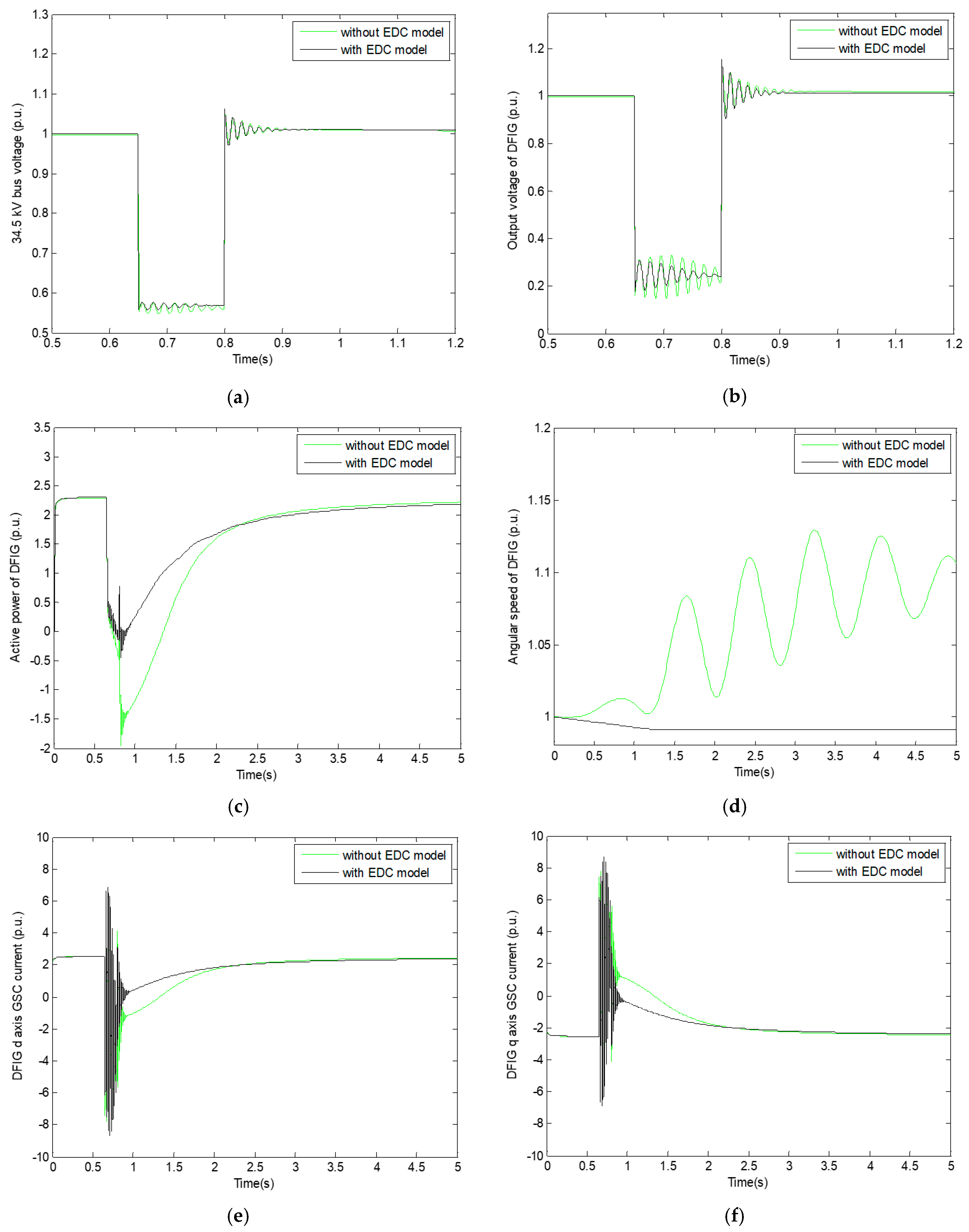
5. Results from the Simulation Study

Three scenarios were examined in detail in this study, which are three-phase fault, two-phase fault, and single-phase ground fault analyses. All three fault times in the analyzed system were determined to be between 0.65 and 0.8 s. In the analyses, comparisons were made between the conventional model and the EDC model. Comparisons are interpreted in detail. The results obtained for a three-phase fault are shown in Figure 4, the results obtained for a two-phase fault are shown in Figure 5, and the results obtained for a single-phase ground fault are shown in Figure 6.
In the three-phase fault analysis performed in the system, it is seen that the EDC model gives better results than the conventional model. When the oscillations at the end of the fault are examined in detail, in the EDC model, the 34.5 bus voltage is 0.57–1.06 p.u., the DFIG output voltage is 0.2–1.19 p.u., the active power is −0.4–2.3 p.u., the angular speed is 0.997–1 p.u., the d axis stator GSC value is −8.6–6.9 p.u., and the q axis stator GSC value is −6.9–8.6 p.u. It has been observed that oscillations occur. When the system is examined in detail in terms of stability periods, it is seen that the 34.5 kV bus voltage becomes stable in the shortest amount of time with the EDC model, while d–q axis stator GSC values become stable in the longest among of time.
In the second analysis performed in this study, the occurrence of two-phase faults was examined. For this fault, it has been observed that the EDC model gives more effective results in terms of stability and oscillations than the conventionally used model. It was observed that in the case of a two-phase fault, as in a three-phase fault, the 34.5 kV bus voltage became stable in the shortest amount of time, while the d–q axis stator GSC values became stable in the longest amount of time. When the oscillation ranges in two-phase faults are examined in detail with the EDC model, 34.5 bus voltage is 0.68–1.04 p.u., DFIG output voltage is 0.2–1.06 p.u., active power is −0.9–2.3 p.u., angular speed is 0.998–1 p.u., the d axis stator GSC value is −1.4–4.8 p.u., and angular speed value is −4.8–1.4 p.u. It has been determined that oscillations occur.
In the final analysis of the study, comparisons between the conventional model and the EDC model in a phase ground fault are included. It is seen that less oscillations occur in a phase ground fault compared to other faults during the fault duration between 0.65 and 0.8 s. With the EDC model, 34.5 bus voltage is 0.57–1.02 p.u., DFIG output voltage is 0.65–1.06 p.u., active power is 1.3–2.3 p.u., angular speed is 0.998–1 p.u., d axis stator GSC value is −0.01–4 p.u., and q axis stator GSC value is −4–0.01 p.u. It was observed that they had minimum and maximum oscillations in their values. While the parameter value that became stable in the shortest amount of time was 34.5 kV bus voltage, the parameter value that became stable in the longest amount of time was the d–q axis stator GSC values.

6. Conclusions

In this study, the goal was to develop a demagnetization model to strengthen the stator flux and compensate for the voltage drop during balanced and unbalanced faults. In addition, a stator dynamic model has been developed to facilitate the simulation study calculation in transient stability situations. Both models developed are electromotive force-based. With the development of natural flux and forced flux models and the optimal determination of the reference rotor current value during transient stability, the system became stable in a short amount of time, as seen in the study. It was observed that the oscillations were quickly dampened in all parameters compared to during transient stability. Calculation performance has increased due to the stator dynamic model developed in the EDC model. In the comparisons made for fault analysis, it was seen that system oscillations were lower in the case of a single-phase ground fault, and system oscillations were higher in the case of a three-phase fault. The weakness of the developed model is that the parameters used in the machine are selected at appropriate values. This lays the foundations for other studies to use optimization algorithms to determine parameters at more appropriate values. This study paves the way for natural and forced flux model-based electromotive force models to guide different approaches in providing LVRT capability according to grid code requirements. Moreover, by modifying the EDC model to the flux models used in DFIG, it will be possible to better control the excessive oscillations of the back-to-back converter due to time delays during transient stability.

Author Contributions

Conceptualization, M.K.D.; investigation and resources M.K.D. and M.U.D.; writing—original draft preparation M.U.D.; writing—review and editing, M.K.D. and M.U.D.; supervision, M.K.D.; funding acquisition M.K.D. and M.U.D. All authors have read and agreed to the published version of the manuscript.

Funding

This research received no external funding.

Data Availability Statement

The data are contained within the article.

Conflicts of Interest

The authors declare no conflict of interest.

References

  1. Rodríguez, J.M.; Fernández, J.L.; Beato, D.; Iturbe, R.; Usaola, J.; Ledesma, P.; Wilhelmi, J.R. Incidence on power system dynamics of high penetration of fixed speed and doubly fed wind energy systems: Study of the Spanish case. IEEE Trans. Power Syst. 2002, 17, 1089–1095. [Google Scholar] [CrossRef]
  2. Zhu, D.; Zou, X.; Dong, W.; Jiang, C.; Kang, Y. Disturbance feedforward control for type-3 wind turbines to achieve accurate implementation of transient control targets during LVRT. Int. J. Electr. Power Energy Syst. 2020, 119, 105954. [Google Scholar] [CrossRef]
  3. Liang, J.; Howard, D.F.; Restrepo, J.A.; Harley, R.G. Feedforward transient compensation control for DFIG wind turbines during both balanced and unbalanced grid disturbances. IEEE Trans. Ind. Appl. 2013, 49, 1452–1463. [Google Scholar] [CrossRef]
  4. Zhu, D.; Zou, X.; Zhou, S.; Dong, W.; Kang, Y.; Hu, J. Feedforward current references control for DFIG-based wind turbine to improve transient control performance during grid faults. IEEE Trans. Energy Convers. 2017, 33, 670–681. [Google Scholar] [CrossRef]
  5. Chang, Y.; Kocar, I.; Hu, J.; Berger, M. Comparison of internal voltage vectors of DFIG-based wind turbine generator and synchronous generator during asymmetrical fault. Electr. Power Syst. Res. 2023, 223, 109628. [Google Scholar] [CrossRef]
  6. Alsmadi, Y.M.; Xu, L.; Blaabjerg, F.; Ortega, A.J.P.; Abdelaziz, A.Y.; Wang, A.; Albataineh, Z. Detailed investigation and performance improvement of the dynamic behavior of grid-connected DFIG-based wind turbines under LVRT conditions. IEEE Trans. Ind. Appl. 2018, 54, 4795–4812. [Google Scholar] [CrossRef]
  7. Taveiros, F.E.V.; Barros, L.S.; Costa, F.B. Heightened state-feedback predictive control for DFIG-based wind turbines to enhance its LVRT performance. Int. J. Electr. Power Energy Syst. 2019, 104, 943–956. [Google Scholar] [CrossRef]
  8. Shahriari, S.A.A.; Mohammadi, M.; Raoofat, M. A new method based on state-estimation technique to enhance low-voltage ride-through capability of doubly-fed induction generator wind turbines. Int. J. Electr. Power Energy Syst. 2018, 95, 118–127. [Google Scholar] [CrossRef]
  9. Ardjoun, S.A.E.M.; Denai, M.; Abid, M. A robust power control strategy to enhance LVRT capability of grid-connected DFIG-based wind energy systems. Wind Energy 2019, 22, 834–847. [Google Scholar] [CrossRef]
  10. Uddin, M.N.; Arifin, M.S.; Rezaei, N. A novel neuro-fuzzy based direct power control of a DFIG based wind farm incorporated with distance protection scheme and LVRT capability. IEEE Trans. Ind. Appl. 2023, 59, 5792–5803. [Google Scholar] [CrossRef]
  11. Huang, J.; Zhang, L.; Sang, S.; Xue, X.; Zhang, X.; Sun, T.; Gao, N. Optimized series dynamic braking resistor for LVRT of doubly-fed induction generator with uncertain fault scenarios. IEEE Access 2022, 10, 22533–22546. [Google Scholar] [CrossRef]
  12. Dong, H.; Wu, H.; Pan, J.; Chen, Y.; Xu, B. Research on double-fed induction generator low voltage ride through based on double braking resistors using fuzzy control. Energies 2018, 11, 1155. [Google Scholar] [CrossRef]
  13. Ghorbani, M.; Firouzi, M.; Mozafari, B.; Golshan, F. Power flow management and LVRT enhancement by using multi-functional capacitive bridge-type fault current limiter in DFIG system. Int. J. Electr. Power Energy Syst. 2023, 148, 108810. [Google Scholar] [CrossRef]
  14. Chakraborty, A.; Maity, T. Integrated control algorithm for fast and accurate detection of the voltage sag with low voltage ride-through (LVRT) enhancement for doubly-fed induction generator (DFIG) based wind turbines. Control Eng. Pract. 2023, 131, 105393. [Google Scholar] [CrossRef]
  15. Shanmugam, R.; Sakthivel, D.K.; Ramaiah, A.N.; Ramalingam, S. Nonlinear Control Strategy for DC-Link Voltage Control in a DFIG of WECS During 3φ Grid Faults. IEEE Trans. Ind. Electron. 2024, 71, 12468–12475. [Google Scholar] [CrossRef]
  16. Döşoğlu, M.K. Hybrid control approach for low-voltage ride-through capability in doubly-fed induction generator-based wind turbines. Comput. Electr. Eng. 2021, 90, 106972. [Google Scholar] [CrossRef]
  17. Hiremath, R.; Moger, T. Modified Super Twisting algorithm based sliding mode control for LVRT enhancement of DFIG driven wind system. Energy Rep. 2022, 8, 3600–3613. [Google Scholar] [CrossRef]
  18. Chowdhury, M.A.; Shafiullah, G.M.; Ferdous, S.M. Low voltage ride-through augmentation of DFIG wind turbines by simultaneous control of back-to-back converter using partial feedback linearization technique. Int. J. Electr. Power Energy Syst. 2023, 153, 109394. [Google Scholar] [CrossRef]
  19. Delavari, H.; Veisi, A. A new robust nonlinear controller for fractional model of wind turbine based DFIG with a novel disturbance observer. Energy Syst. 2024, 15, 827–861. [Google Scholar] [CrossRef]
  20. Beltran-Pulido, A.; Cortes-Romero, J.; Coral-Enriquez, H. Robust active disturbance rejection control for LVRT capability enhancement of DFIG-based wind turbines. Control Eng. Pract. 2018, 77, 174–189. [Google Scholar] [CrossRef]
  21. Huang, C.; Zhao, H. Error-based active disturbance rejection control for wind turbine output power regulation. IEEE Trans. Sustain. Energy 2023, 14, 1692–1701. [Google Scholar] [CrossRef]
  22. López, J.; Gubía, E.; Olea, E.; Ruiz, J.; Marroyo, L. Ride through of wind turbines with doubly fed induction generator under symmetrical voltage dips. IEEE Trans. Ind. Electron. 2009, 56, 4246–4254. [Google Scholar] [CrossRef]
  23. Mendes, V.F.; de Sousa, C.V.; Silva, S.; Rabelo, B.C.; Hofmann, W. Modeling and ride-through control of doubly fed induction generators during symmetrical voltage sags. IEEE Trans. Energy Convers. 2011, 26, 1161–1171. [Google Scholar] [CrossRef]
  24. Krause, P.C. Analysis of Electric Machinery, 2nd ed.; McGraw-Hill: New York, NY, USA, 2002. [Google Scholar]
  25. Kundur, P. Power System Stability and Control; Tata McGraw-Hill Education: New York, NY, USA, 1994. [Google Scholar]
  26. Ekanayake, J.B.; Holdsworth, L.; Jenkins, N. Comparison of 5th order and 3rd order machine models for double fed induction generators (DFIG) wind turbines. Electr. Power Syst. Res. 2003, 67, 207–215. [Google Scholar] [CrossRef]
  27. Patel, K.; Das, S.P. Improved Traditional Demagnetization Control of DFIG Under Balanced Grid Faults. In Proceedings of the 2020 IEEE International Conference on Power Electronics, Drives and Energy Systems (PEDES), Jaipur, India, 16–19 December 2020. [Google Scholar]
  28. Döşoğlu, M.K.; Özkaraca, O.; Güvenç, U. Novel active–passive compensator–supercapacitor modeling for low-voltage ride-through capability in DFIG-based wind turbines. Electr. Eng. 2019, 101, 1119–1132. [Google Scholar] [CrossRef]
Figure 1. Circuit model of DFIG.
Energies 17 04015 g001
Figure 2. Enhanced Demagnetization Control (EDC) model.
Energies 17 04015 g002
Figure 3. The analyzed system.
Energies 17 04015 g003
Figure 4. (af) Comparisons of conventional and EDC models in a three-phase fault.
Energies 17 04015 g004
Figure 5. (af) Comparisons of conventional and EDC models in a two-phase fault.
Energies 17 04015 g005
Figure 6. (af) Comparisons of conventional and EDC models in a single-phase ground fault.
Energies 17 04015 g006
Table 1. Comparisons made from some literature studies.
LiteratureMethodDeveloped LVRT
Capability Strategy
PurposeResult
Ref. [4]Feed-forward controlPositive and negative sequence flux modelsReducing overvoltages and overcurrents in the RSC circuitIt gives effective results. However, the work done is costly.
Ref. [6]Dynamic modelPositive, negative and natural sequence flux modelsProtecting the RSC circuit against transient instabilityIt gives effective results. However, the oscillations have been relatively dampened.
Ref. [22]Crowbar modelPositive, negative and natural sequence flux modelsReducing maximum rotor currentIt gives effective results. However, a large current capacity problem arises in the rotor converter.
Ref. [23]Magnetizing current controlPositive, negative, natural and forced sequence flux modelsImproving system stability during faultsIt gives effective results. However, it takes time for the oscillations to dampen.
In this studyEnhanced demagnetization control modelPositive, negative, natural, forced sequence flux models and stator dynamic modelsDamping oscillations, overcurrent and voltage reduction, and stabilizing the system in a short amount of time, ease of calculation in simulation workIt is effective against various transient stability states.
Disclaimer/Publisher’s Note: The statements, opinions and data contained in all publications are solely those of the individual author(s) and contributor(s) and not of MDPI and/or the editor(s). MDPI and/or the editor(s) disclaim responsibility for any injury to people or property resulting from any ideas, methods, instructions or products referred to in the content.

