Review

A Review of Hydrogen Leak Detection Regulations and Technologies

1
Department of Mechanical Engineering, University of Ottawa, Ottawa, ON K1N 6N5, Canada
2
National Research Council Canada, Ottawa, ON K1A 0R6, Canada
*
Author to whom correspondence should be addressed.
Energies 2024, 17(16), 4059; https://doi.org/10.3390/en17164059
Submission received: 18 July 2024 / Revised: 4 August 2024 / Accepted: 9 August 2024 / Published: 15 August 2024
(This article belongs to the Section A5: Hydrogen Energy)

Abstract

:
Hydrogen (H2) is positioned as a key solution to the decarbonization challenge in both the energy and transportation sectors. While hydrogen is a clean and versatile energy carrier, it poses significant safety risks due to its wide flammability range and high detonation potential. Hydrogen leaks can occur throughout the hydrogen value chain, including production, storage, transportation, and utilization. Thus, effective leak detection systems are essential for the safe handling, storage, and transportation of hydrogen. This review aims to survey relevant codes and standards governing hydrogen-leak detection and evaluate various sensing technologies based on their working principles and effectiveness. Our analysis highlights the strengths and limitations of the current detection technologies, emphasizing the challenges in achieving sensitive and specific hydrogen detection. The results of this review provide critical insights into the existing technologies and regulatory frameworks, informing future advancements in hydrogen safety protocols.

1. Introduction

Hydrogen is gaining significant attention as an energy carrier due to its great potential in the transition to a low-carbon economy. As the most abundant element in the universe, hydrogen can be produced from various sources, including fossil fuels, biomass, and electrolysis of water using renewable energy. When used as a fuel, hydrogen produces only water as the product, making it a natural zero-carbon fuel option [1,2].
In Canada, hydrogen holds particular importance due to the country’s vast renewable energy resources, including hydroelectric power and wind energy. The Canadian government has recognized the potential of hydrogen in achieving its climate-change goals, including the commitment to net-zero greenhouse gas emissions by 2050 [3]. By leveraging its renewable energy capacity, Canada aims to become a global leader in the production, distribution, and utilization of clean hydrogen. The use of hydrogen as a power source in Canada offers several key benefits. First, it enables the decarbonization of various end-use sectors—transportation, in particular. For example, hydrogen can be used as a fuel for fuel-cell electric vehicles (FCEVs), providing long-range and quick refueling capabilities, while emitting zero tailpipe emissions. Additionally, hydrogen can replace fossil fuels in industrial processes, such as steelmaking or chemical production, reducing carbon dioxide emissions significantly. Furthermore, hydrogen can be utilized for heating applications in residential and commercial buildings, contributing to the shift away from fossil fuel-based heating systems.
Hydrogen leak detection is of utmost importance in Canada’s hydrogen economy. While hydrogen is a clean and versatile energy carrier, it poses safety risks due to its wide flammability range and great potential for explosion. The flammability range of hydrogen is between 4 and 75 vol% in air, and it becomes explosive within a wide range of concentrations (18–59%) at standard atmospheric conditions [4]. Hydrogen leaks can occur in various stages of the hydrogen value chain, including production, storage, transportation, and utilization. Effective hydrogen leak-detection systems and protocols are essential to ensure the safe handling, storage, and transportation of hydrogen. Early detection of leaks is critical for preventing accidents, protecting workers and the public, and avoiding potential damage to infrastructure. Hydrogen leak-detection systems employ technologies such as sensors, detectors, and monitoring equipment to identify leaks promptly. These systems can detect leaks in various settings, including hydrogen production facilities, storage tanks, pipelines, and refueling stations.
In Canada, the importance of hydrogen leak detection is amplified by the country’s ambition to develop a robust hydrogen infrastructure. Investments are being made to establish hydrogen production hubs, build hydrogen refueling stations, and integrate hydrogen into existing energy systems. With these developments, ensuring the safety of hydrogen infrastructure and operations becomes vital. By prioritizing hydrogen leak detection, Canada can build public confidence in hydrogen technologies and maintain a strong safety record. Moreover, robust leak detection measures contribute to the long-term viability and sustainability of the hydrogen sector.
Furthermore, when it comes to the storage of hydrogen, subsurface formations such as natural gas reservoirs, salt caverns, and saline aquifers offer a substantial potential due to their established infrastructure, geological stability, and capacity to store large volumes of gas. By repurposing these formations for hydrogen storage, the energy industry can leverage existing expertise and infrastructure, thereby accelerating the deployment of hydrogen as a mainstream energy solution. One notable advantage of subsurface hydrogen storage is its potential to enhance energy reliability and grid stability. Hydrogen storage can bridge the gap between variable renewable energy production and demand fluctuations by allowing excess energy to be stored during periods of high generation and released during periods of high demand. This capability can contribute to a more resilient energy system and facilitate the effective integration of intermittent renewable sources like wind and solar into the grid. Moreover, utilizing existing subsurface storage fields for hydrogen offers a sustainable and cost-effective approach, minimizing the need for building entirely new infrastructure.

2. Review of Codes and Standards

There are several codes and standards for hydrogen systems that aim to ensure the safety, reliability, and performance of these technologies. Some of the most widely used codes and standards are developed by organizations such as the International Organization for Standardization (ISO), the American Society of Mechanical Engineers (ASME), the National Fire Protection Association (NFPA), and the International Electrotechnical Commission (IEC). It is important to differentiate between mandatory and voluntary documents that are used to define safety and quality requirements for goods and services, as defined by the Standards Council of Canada [5]:
  • Code: A code is broad in scope and is intended to carry the force of law when adopted by a provincial, territorial, or municipal authority. Codes may include references to a number of standards.
  • Standard: A standard is a document that provides a set of agreed-upon rules, guidelines, or characteristics for activities or their results. Standards establish accepted practices, technical requirements, and terminologies for diverse fields.

2.1. Requirements for General Hydrogen Systems and Technologies

Table 1 lists some of the standards, codes, and relevant documents concerning general hydrogen systems and technologies. These documents cover various aspects of hydrogen systems, such as design, installation, operation, maintenance, testing, and inspection. However, most of these documents do not provide guidance on handling potential hazards, such as leakage mitigation.
ASME B31.12, for example, establishes a procedure according to which leakage indications of flammable gas can be graded and controlled [6]. Grade 1 leaks are of the highest level of threat and represent situations in which the leak poses an immediate hazard to persons or properties and requires immediate intervention. Grade 2 leaks represent situations in which the leak is non-hazardous at the time of detection but could lead to a future hazardous event, thus requiring a scheduled repair. Finally, grade 3 leaks are considered non-hazardous at the time of detection and can be reasonably expected to remain so for the foreseeable future. This classification is shown in Table 2, with examples and reading ranges expressed in percentages of the lower explosive limit (LEL), which is 4 vol% H2 in air.

2.2. Sensor Testing Requirements

Table 3 lists codes and standards that specify requirements and recommendations on a range of scenarios concerning hydrogen leak detection, including sensor selection/installation, calibration/testing, and response/notification protocols in the event of a hydrogen release. The purpose of these codes and standards is to ensure that gas detection systems are reliable; effective; and capable of protecting personnel, facilities, and the environment from the hazards associated with hydrogen gas. These documents present testing requirements applicable to a product standard for hydrogen detection apparatus, and are intended to be used by manufacturers to assess and certify their products.
ISO 26142, for example, is an international standard prepared by the Technical Committee ISO/TC 197 that was published in 2010 and was last reviewed and confirmed in 2021 [7]. Intended to be used for product certification purposes, the standard defines the performance requirements of hydrogen-detection apparatuses designed to measure and monitor hydrogen concentrations in stationary applications based on certain testing criteria. The standard covers the hydrogen-detection apparatuses used to achieve single and/or multilevel safety operations, such as nitrogen purging, ventilation, and/or system shut-off corresponding to the hydrogen concentration. The standard sets out the requirements applicable to a product standard for hydrogen-detection apparatuses, such as precision, response time, stability, measuring range, selectivity, and poisoning. The appendices also present two testing methods commonly used in the industry: the chamber test method and the flow-through test method. Both test procedures are described to determine the time of response and recovery, and the advantages and disadvantages of each method are presented. Similar testing procedures are also documented in the SAE J3089 Technical Information Report (TIR) and were derived from methods originally developed by researchers at the NREL Hydrogen Safety Test Laboratory [8]. The UL 2075 is another standard that is commonly referred to and is considered a complete product assembly performance listing standard that applies to fixed, portable, and transportable toxic and combustible gas and vapor detectors and sensors [9]. Another standard is CSA C22.2 No. 60079-29-1:17, which is a national standard of Canada published by the CSA group adopted from an IEC standard [10]. It specifies general requirements for construction, testing, and performance. It also describes the test methods which apply to portable, transportable, and fixed equipment for the detection of flammable gas or vapor concentrations in the air. Table 4 compares some of the testing requirements specified in these standards.

2.3. Specific Requirements for Hydrogen Leak-Detection Instruments

Depending on the target application, the sensor-performance requirements could vary. However, the U.S. Department of Energy (DOE) identified in their 2007 Multi-Year Program Plan (MYPP) several key target performance metrics for hydrogen sensors for the purposes of research and development [11]. These metrics displayed in Table 5 are rather general and do not account for different usage scenarios. It was later recognized that different applications can have significantly different requirements. In 2011, the U.S. National Renewable Energy Laboratory (NREL) organized a sensor workshop where a panel of researchers and industry experts agreed upon sensor requirements for various usage scenarios [12]. Some of these applications included on-board deployment for light-duty road vehicles and industrial trucks, indoor fueling-facility monitoring and in-dispenser deployment, residential applications, production plants, battery backup systems, and hydrogen storage applications, both indoors and outdoors. For example, in indoor hydrogen storage applications, a required linear measuring range was determined to be 0–4 vol% H2, but an extension up to 10% was identified to be useful or even required by a local Authority Having Jurisdiction (AHJ). Other analytical parameters include sensor drift, which is required to be less than 10% of the alarm level and output no false positives or negatives. In addition, the sensor must be stable in temperatures ranging from 0° to 40 °C for most applications but can go as low as −25 °C for refrigerated spaces. The operating relative humidity range must also be between 25% and 95% RH at the prevailing temperature in an unregulated facility. The sensor is also required to be selective and not show cross-sensitivity behaviors towards CO, H2S, or other application-specific gases and chemicals. It is also required to have a response time of at least 30 s at 1 vol% H2 or the alarm level. There are other operational and deployment requirements, such as being commercially mature and purchasable off-the-shelf and having a lifetime of at least 5 years.

3. Review of Sensor Performance Metrics

An expanded compilation of potential performance metrics with brief definitions is presented in Table 6. These specifications encompass a wide spectrum, ranging from analytical metrics to operational and deployment logistical parameters. While some of these metrics are covered by standards, it is worth noting that there is no one-size-fits-all technology for hydrogen sensing. As such, the values and significance of each parameter are specific to the application, and the relative importance of a particular parameter will vary significantly across different use cases.

4. Review of Hydrogen Sensing Technologies

There are numerous mechanisms that H2 sensors use to detect and quantify hydrogen leakage. This section provides an overview of sensing mechanisms, emphasizing their working principles and performance characteristics. Throughout, the advantages and disadvantages of each sensor technology are evaluated and discussed here to provide a comprehensive overview of their respective strengths and limitations.

4.1. Electrochemical Sensors

Electrochemical sensors function by detecting the change in charge transport or electrical characteristics resulting from electrochemical reactions taking place at a sensing electrode. These sensors are highly reconfigurable and can be used to detect a wide range of combustible gases at different performance targets. There are two primary embodiments of electrochemical sensors: the amperometric and potentiometric types.

4.1.1. Amperometric Type

The amperometric-type electrochemical sensors function at a constant applied voltage and rely on measuring a current proportional to the concentration of diffused hydrogen in the working electrolyte. They typically consist of three major constituents, as seen in Figure 1: the electrodes, the electrochemical cell, and the gas-permeable layer. The electrodes consist of a working (or sensing) electrode and a counter electrode. They can also include a reference electrode coupled with a potentiostat to keep the voltage constant across both ends. The electrodes are typically constructed of a noble metal, such as platinum or palladium, which acts as a catalyst, facilitating the hydrogen oxidation reaction on the surface. In addition, the electrochemical cell contains an electrolyte, which can be of a liquid or a solid nature, allowing for the transfer of hydrogen ions between the two electrodes. Finally, the gas-permeable layer limits the amount of gas that is passing through to the working electrode. This layer is typically composed of a perfluorinated polymer, such as Teflon, and can also act as a filter to reduce the passthrough of other gases, thus increasing selectivity. When a target analyte interacts with the working electrode, it undergoes an electrochemical reaction, which leads to the generation or consumption of electrons according to the equation H2 → 2H+ + 2e [13]. This results in a change in the current flowing between the two electrodes. At the counter electrode, the reduction of oxygen takes place according to the equation ½ O2 + 2H+ + 2e → H2O. A meter is connected between the two electrodes that measures the electric current proportional to the concentration of the analyte gas according to Faraday’s law of electrolysis [14].
Sulfuric acid is the most used liquid electrolyte [15]. However, solid electrolytes have been utilized more recently due to their mitigation of problems such as leakage and corrosion. For example, Nafion perfluoro sulfonic acid (PFSA) membranes are used in electrochemical cells, functioning as cation-conducting solid electrolytes [16,17]. In another recent study, Gao et al. [18] developed an advanced amperometric hydrogen sensor featuring a unique “sandwich” structure comprising a titanium foam electrode loaded with platinum nanoparticles (Pt-NPs) and a solid polymer electrolyte. This design enables direct gas diffusion to the active interface, significantly enhancing the sensor’s electrochemical performance. The sensor demonstrated high sensitivity, stability, and a low detection limit for hydrogen, making it highly effective for real-time monitoring, especially in applications like lithium-ion battery safety. Table 7 lists some of the advantages and disadvantages of amperometric-type electrochemical sensors.

4.1.2. Potentiometric Type

In contrast to amperometric-type electrochemical sensors, potentiometric sensors typically operate at a close-to-zero current, and the potential difference is related to the amount of gas measured. The structure of potentiometric sensors is similar to that of their amperometric counterpart, consisting of two electrodes with an electrolyte in between. Similarly, the electrodes are constructed of noble metals, such as palladium, platinum, gold, or silver [20,21]. As for the electrolyte, proton conducting solids are typically used, such as alpha-alumina [22], phosphoro-silica glass [23], NASICONs [24], and many others.
In a recent publication, Yi et al. introduced a high-performance potentiometric hydrogen sensor utilizing a hierarchical porous, hollow SnO2 nanofiber sensing electrode [25]. This innovative electrode features a three-dimensional scaffold architecture that provides high porosity, a large pore size, and excellent pore interconnectivity, significantly enhancing gas transport. The sensor demonstrated a remarkable performance, with a response time of 5 s for 1000 ppm H2 at 450 °C, outperforming similar sensors with nanoparticle-based electrodes. The sensor also exhibited excellent selectivity, repeatability, and stability. This superior performance is attributed to the unique morphology of the hierarchical nanofibers, facilitating faster gas diffusion and a higher hydrogen concentration at the boundary. Table 8 lists some of the advantages and disadvantages of potentiometric-type electrochemical sensors.

4.2. Catalytic Sensors

Catalytic sensors operate on the reactionary principle of catalytic behavior. In the case of a hydrogen sensor, H2 reacts with O2 on the catalytic sensor surface, producing heat. The production of heat can be quantized and related to the concentration of hydrogen, which has a standard heat of combustion of 141.9 kJ/g. There are two main types of catalytic-based sensors: the pellistor type and the thermoelectric type.

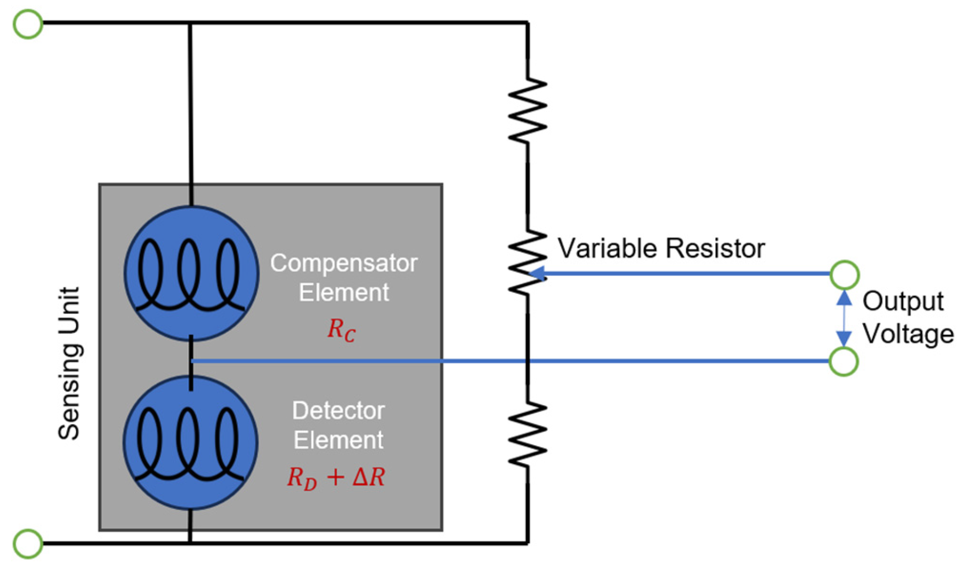
4.2.1. Pellistor Type

As seen in Figure 2, pellistor-type hydrogen gas sensors are composed of two elements: a detector and a compensator element. Each element is a platinum coil embedded in a pallet or ceramic bead. These coils have a double function since they act as both a heater and a resistance thermometer. The bead surface of the detector element is activated with a catalytic material, usually a noble metal, such as platinum or palladium, while the compensator bead is inert. A Wheatstone bridge circuit is typically formed using both elements, in which a variable resistor is adjusted to balance the bridge circuit in clean air, without combustible gases. During the operation of the sensor, an external power source drives a current through a heating element, causing an increase in the temperature of the sensing bead to values typically above 300 °C [19]. At such elevated temperatures, hydrogen molecules chemisorbed on the catalyst sensing bead react with the adsorbed oxygen. This reaction is of an exothermic nature, raising the temperature of the sensing bead, which in turn increases the resistance of the detector element, creating an imbalance in the bridge circuit. Thus, when combustible gases are present, an output voltage signal proportional to the concentration of the combustible gases is produced.
In a recent study, Ivanov et al. developed a highly selective low-temperature catalytic hydrogen sensor [28]. This sensor utilizes a Wheatstone bridge circuit and a divider circuit to measure responses to hydrogen and various hydrocarbons. The sensor operates effectively at temperatures between 66 and 130 °C, demonstrating high sensitivity (25–35 mV/%) and low power consumption (approximately 8.6 mW). The Wheatstone bridge circuit provided superior selectivity and sensitivity, making this sensor a promising tool for detecting hydrogen in the range of pre-explosive concentrations (0.1–2 vol%) with minimal energy requirements. There has also been a focus on miniaturizing pellistor-type catalytic sensors to reduce power consumption and enhance response and recovery times. Lee et al. reported an integrated catalytic combustion hydrogen sensor utilizing MEMS technology [29]. The sensor, which consists of two sensing and two reference elements on a 5.76 mm2 chip, was fabricated using silicon wafers with silicon dioxide and nitride films, patterned through photolithography and electroplating. It detects hydrogen at concentrations as low as 20 ppm, with a low power consumption of 55.68 mW. The sensor also boasts fast response and recovery times of 0.36 and 1.29 s, respectively, to 1000 ppm H2 at an operating voltage of 1 V. Table 9 lists some of the advantages and disadvantages of pellistor-type catalytic sensors.

4.2.2. Thermoelectric Type

The first thermoelectric-type catalytic sensor was reported in 1985 by McAleer et al. [30]. Similar to the pellistor-type sensor, thermoelectric catalytic sensors also rely on the catalyzed exothermic oxidation reaction of hydrogen. However, instead of relying on an increase in resistance as temperature rises, the Seebeck effect occurs when there is a temperature gradient between two areas of a conductor or a semiconductor, producing a measurable voltage difference [31]. Usually, catalytic hydrogen sensors of the thermoelectric type are composed of a thermoelectric film divided into two halves deposited on an insulating substrate material. Half of the film is coated with a catalytic material, usually platinum, due to its high catalytic reactivity at lower temperatures, while the other half is left uncoated. The chosen material for the substrate is typically glass, alumina, or magnesium oxide [32].
Recently, Panama and Lee demonstrated a catalytic thermoelectric hydrogen sensor using a CoSb3 thermopile fabricated by single-step deposition on bare and textured glass [33]. The sensor features a Co-In-Sb stack with a SiO2 capping layer, which was deposited via an e-beam evaporator. The combination forms a thermoelectric pair through thermal activation. This innovative method allows for the simultaneous creation of p-type CoSb3 on bare glass and n-type CoSb3 on textured glass. The resulting sensor, incorporating 41 thermoelectric pairs, has a thermoelectric sensitivity of 1.6 mV/K and demonstrates a steady-state voltage of 13 mV for 1% H2 in air at room temperature. Table 10 lists some of the advantages and disadvantages of thermoelectric-type catalytic sensors.

4.3. Resistance-Based Sensors

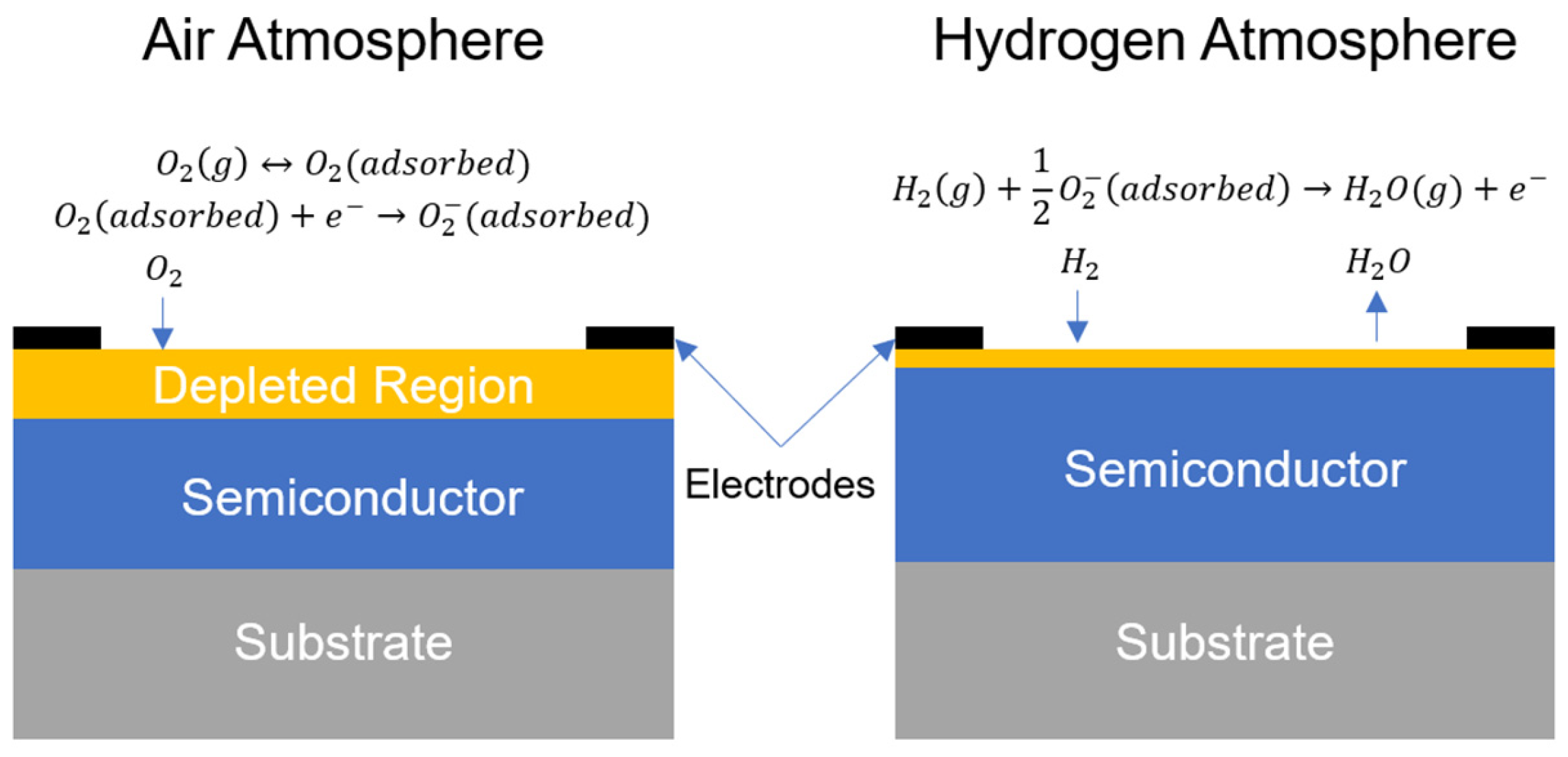
4.3.1. Semiconducting Metal-Oxide Type

Resistance-based semiconducting metal oxide (MOS)-type sensors detect the concentration of various types of reducing gases by measuring the resistance change in the metal oxide due to the adsorption of reducing gases. Typically, a metal oxide film is applied on an insulating substrate between two electrodes, coupled with a heating element placed on the reverse side. The substrate material of choice is usually aluminum oxide due to its high thermal stability and electrical resistance, while allowing the effective adherence of metal oxides to it. When the sensor is in operation, the film is typically heated to temperatures between 180 and 450 °C, depending on the specific metal oxide chosen [19]. At such elevated temperatures, the reaction with the reducing gas is enhanced, and the trace amount of water resulting from the reaction is removed. A wide range of semiconductor oxides can be used to detect hydrogen, including but not limited to tin, zinc, and iron oxides [35].
The working principle of resistance-based metal oxide sensors is based on the change in the surface electron depletion region when hydrogen reacts with the chemisorbed oxygen on the surface of the semiconductor. As seen in Figure 3, oxygen molecules have the ability to be adsorbed onto the semiconductor’s surface in the presence of an air atmosphere, where they can draw electrons from the conduction band, forming oxygen ions. This results in the creation of an electron-depletion region close to the surface, leading to a significant increase in resistance caused by the reduction in the net carrier density. When the sensor is exposed to a hydrogen atmosphere, the hydrogen molecules undergo an exothermic redox reaction with the adsorbed oxygen species, leading to the rapid desorption of the resulting water molecules. The freed electrons diminish the thickness of the depletion region, leading to a decrease in the semiconductor resistance. When the sensor is returned to a hydrogen-free atmosphere, the depletion-region thickness increases again, thereby increasing the resistance of the semiconductor.
Recently, there has been a need for small-sized, low-power-consumption MOS sensors that utilize micro-electro-mechanical systems (MEMSs). Gorokh et al. described the development of a micropowered chemoresistive gas sensor utilizing a thin alumina nanoporous membrane and a three-component nanocomposite structure based on Sn-O/Bi-O/Mo-O metal oxides [36]. The sensor’s design leverages the high specific surface area and ordered structure of the anodic alumina matrix, combined with the sensitivity of the nanocomposite structure to hydrogen gas. The sensor reportedly operates efficiently at a low power consumption of 10 mW and shows a sensitivity of 0.22 and 0.40 for hydrogen concentrations of 5 and 40 ppm, respectively, at 250 °C. Other high-performance flexible room-temperature MOS sensors have been heavily explored recently [37], including those based on MOS modified with noble metal nanoparticles [38,39], organic polymers [40], and carbon-based materials [41], among others. Table 11 lists some of the advantages and disadvantages of semiconducting metal oxide-type sensors.

4.3.2. Metallic-Resistor Type (Thin-Film Resistor)

Metallic-resistor hydrogen sensors operate on the principle that the electrical resistivity of certain metals and alloys undergoes significant changes upon the absorption of hydrogen gas. Among these metals, palladium stands out due to its high solubility to hydrogen, and the interaction between them is also selective, making palladium the metal of choice for this type of sensor. The detection mechanism in metallic-resistor hydrogen sensors relies on detecting the increase in electrical resistivity that occurs when hydrogen is absorbed from the surrounding environment. This increase in resistivity is attributed to the higher electrical resistance of palladium hydride compared to pure palladium. As hydrogen molecules are absorbed, the electrical resistance of the palladium film changes, providing a measurable signal indicative of the hydrogen concentration in the environment. To fabricate metallic-resistor sensors, a thin film of the metal (e.g., palladium) is deposited onto a substrate using techniques such as vacuum evaporation, electrodeposition, sputtering, or pulsed laser deposition [19]. The substrate, commonly made of silicon, acts as a support structure for the metal film and is placed between two electrical contacts. These contacts allow for the measurement of the electrical resistance changes in the palladium film when exposed to hydrogen gas.
Recently, Gong et al. reported the development of a MEMS-based resistive hydrogen sensor utilizing a palladium–gold alloy thin film [42]. The sensor was fabricated using DC magnetron sputtering deposition, followed by annealing at various temperatures. Integrated onto a patterned silicon substrate with heating and temperature detection resistances, the sensor exhibited an optimal performance at a working temperature of 60 °C and can detect hydrogen at concentrations ranging from 5 ppm to 30,000 ppm, with response and recovery times of 22 and 160 s, respectively, at 30,000 ppm. The sensor also showed excellent repeatability, long-term stability, low power consumption, and high selectivity for hydrogen. Other attempts were also made to miniaturize and decrease power consumption of thin film resistive sensors [43,44,45,46], which makes this technology promising for applications with power and weight constraints. Table 12 lists some of the advantages and disadvantages of metallic resistor-type catalytic sensors.

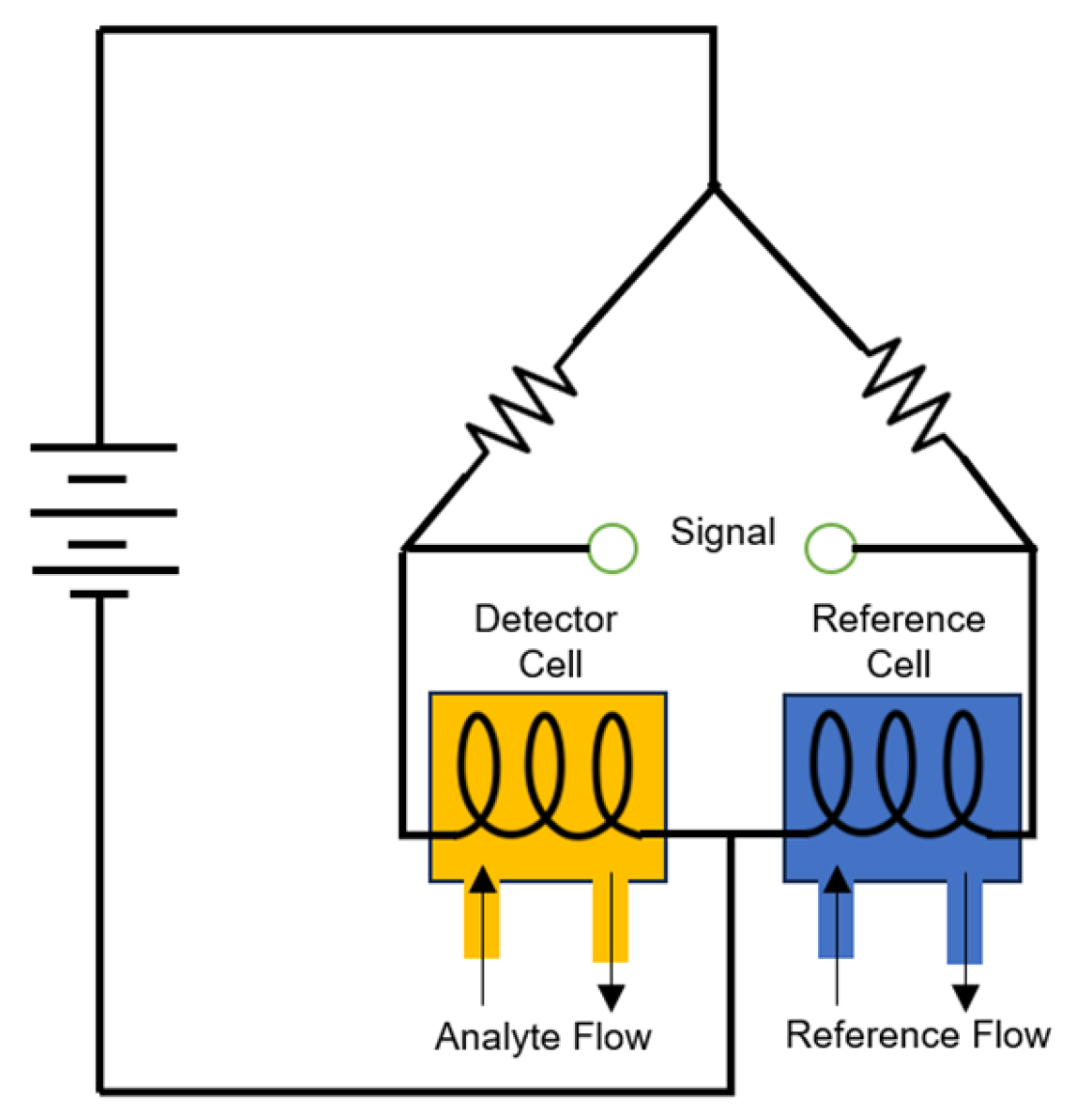
4.4. Thermal Conductivity Type

Thermal conductivity-based sensors are one of the earliest types of hydrogen sensors used. The method is based on the discovery by Andrews in 1840 that changes in the composition of the gas surrounding a heated electrical wire result in changes in the resistivity of the wire [49]. The technology then came into realization thanks to the efforts of Daynes in 1933 [50]. These sensors rely on hydrogen’s relatively high thermal conductivity when compared to air (0.174 vs. 0.026 W/m·K at 20 °C, respectively) to measure the hydrogen concentration in air by measuring heat loss from a hot body to the surrounding gas. There are two main types of these sensors with similar working principles. The first one is composed of two inert resistor beads, each containing an embedded thermoresistor. As seen in Figure 4, one of the resistors is exposed to the measured gas (detector cell), while the other one is insulated in a chamber that contains a reference gas (reference cell), which typically is air. An analyte elutes and changes the thermal conductivity of the column effluent, changing the thermoresistor temperature of the detector cell. The change in temperature leads to a change in resistance, which is typically detected using a Wheatstone bridge circuit by producing an imbalance that translates to a measurable voltage change. The other type operates without a reference cell and consists of a hot and a cold element, maintained at a constant temperature difference. Thermal conduction occurs through the monitored gas, transferring heat from the hot to the cold element. The power consumption to keep the hot element’s setting temperature directly relates to the thermal conductivity of the gas being monitored, allowing for the detection of the gas composition.
There have recently been attempts at miniaturizing thermal conductivity sensors, making them more power efficient, while reducing fabrication costs. In their study, Berndt et al. developed a MEMS-based thermal conductivity hydrogen sensor [51]. The sensor employs micro-fabrication techniques on silicon wafers, creating a micro-hotplate with a suspended heated filament. This design minimizes power consumption by operating in pulsed mode and ensures thermal decoupling from the substrate to prevent heat loss. The sensor has a measurement range from 500 ppm to at least 4 vol% of H2 in air, with successful measurements in ambient gas temperatures ranging from −15 °C to 84 °C. The authors have noted that humidity significantly affects the sensor’s thermal conductivity, a factor accounted for in both theoretical and experimental analyses. Other thermal conductivity sensors were proposed by Harumoto et al. that utilize sweep heating instead of continuous or pulsed heating, which acquires more information at a lower working temperature, without requiring complex machining or the usage of MEMS technology [52,53]. Table 13 lists some of the advantages and disadvantages of thermal conductivity-type sensors.

4.5. Work Function Sensors

Work function-based sensors typically have a triple-layer structure consisting of a hydrogen-sensitive catalytic metal deposited on an oxide (insulator) layer on top of a semiconductor layer. During their operation, hydrogen atoms diffuse through the metal and get adsorbed at the metal–insulator interface [54]. These positively charged atoms create a dipole layer that causes a shift in the energy levels, thus changing the work function of the metal. The work function is a fundamental property, measured in electron volts, that is related to the energy required to detach one electron from the surface of a material [55]. There are three main types of work function-based sensors, namely metal–semiconductor diodes (Schottky type), metal–insulator–semiconductor transistors (MOSFET type), and metal–insulator–semiconductor capacitors.

4.5.1. Metal–Semiconductor Diodes (Schottky Type)

These types of sensors consist of a metal brought into contact with a semiconductor or, in other variations, with an insulating oxide material in between, as seen in Figure 5. When the metal is brought into contact with the semiconductor, the Fermi level of the semiconductor adjusts to the Fermi level of the dominating metal. This adjustment amount is governed by the Schottky-barrier height, which is equal to the difference in Fermi levels between the two materials [56]. To detect the presence of hydrogen, palladium and platinum are typically used as the catalytic metal. In an environment where hydrogen is present, hydrogen molecules get adsorbed onto the surface of the catalytic metal and disassociate into hydrogen atoms, some of which diffuse into the metal–oxide interface, forming a dipole layer in between. This dipole layer changes the work function of the catalytic metal, which, in this case, is a change in the Schottky-barrier height [57]. This change leads to a change in voltage when a constant bias current is run through the Schottky diode.
Shivaraman et al., in 1979, was one of the earliest to demonstrate that current transport through Schottky barriers formed by palladium on n-type silicon with a thin oxide layer in between is sensitive to hydrogen in the ambient [58]. Since then, numerous Schottky diode sensors have been reported in the literature [59,60,61]. Chen et al. have recently presented a Pd nanoparticle/Pt thin film/GaN/AlGaN-based sensor device for hydrogen detection [62]. The sensor exhibits a response time of 18 s and a recovery time of 12 s at 1 vol% H2 in air at 300 °C. The sensor can detect hydrogen at concentrations as low as 1 ppm, showing high selectivity towards hydrogen over other gases, such as NH3, CH4, C2H5OH, and NO2.

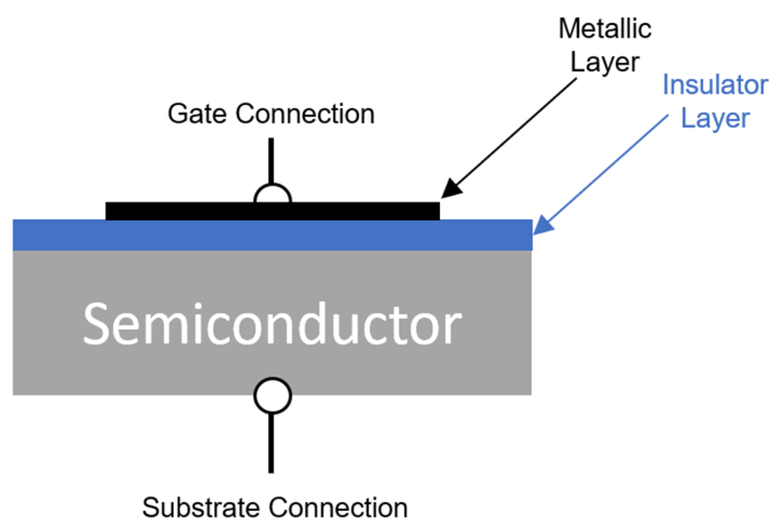
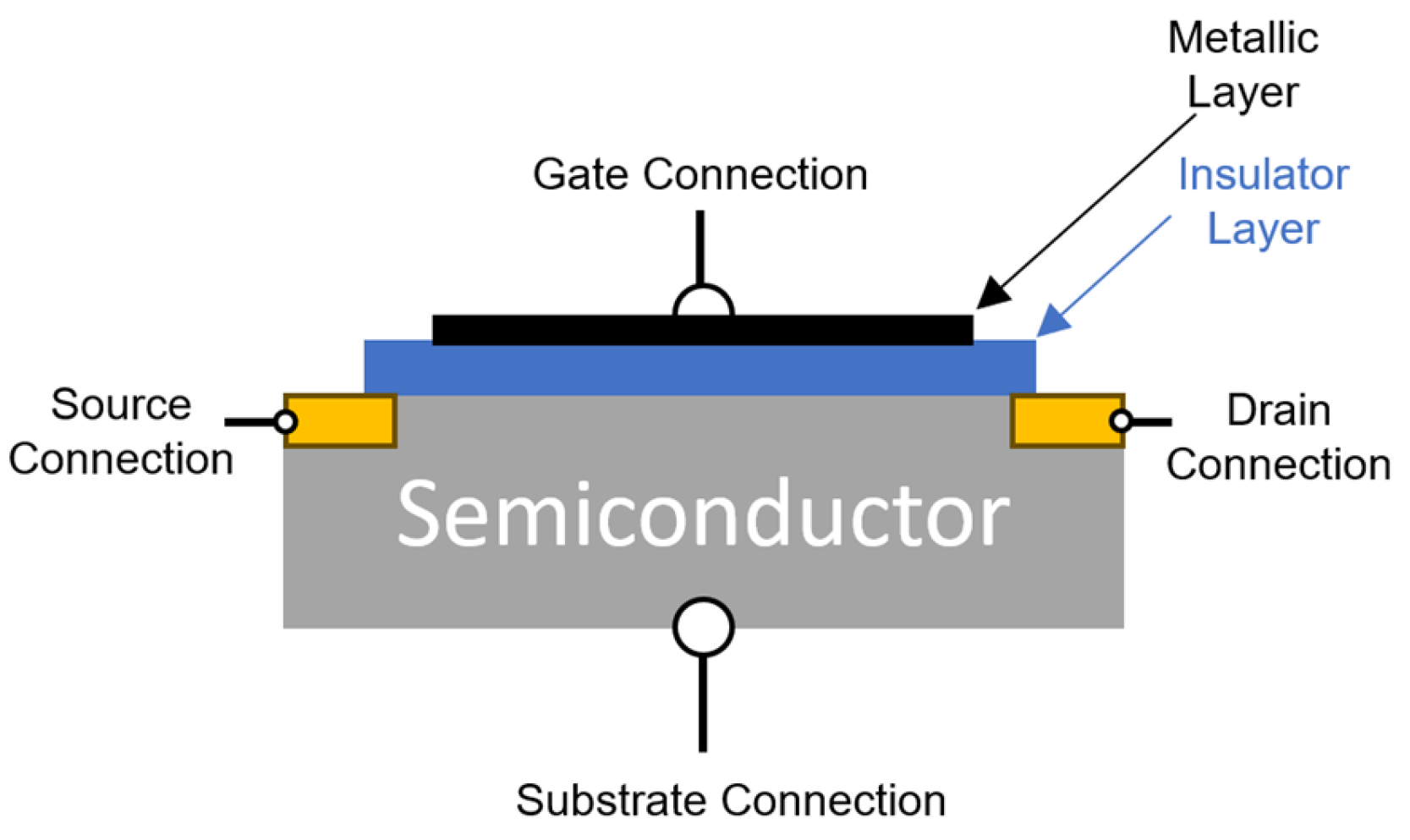
4.5.2. Metal–Insulator–Semiconductor Transistors (MOSFET Type)

These types of sensors rely on a field-effect transistor (FET) to detect hydrogen by transforming the work-function change into a measurable electrical signal. Similar to the Schottky-type sensors, a metallic layer sensitive to hydrogen is deposited onto an oxide layer on top of a semiconducting layer, as seen in Figure 6. Hydrogen-sensing MOSFET sensors have a triple-layer structure typically composed of palladium or platinum, silicon dioxide, and silicon [19]. In contrast to Schottky-type sensors, two regions of the semiconducting layer are ion-implanted in MOSFET sensors to form a drain and a source. The catalytic metal layer functions as a gate and, by applying a positive bias voltage, allows the control of the conductivity between the source and the drain. When hydrogen is present, the molecules get adsorbed onto the metal surface and then disassociate into hydrogen atoms that diffuse to the metal–insulator interface, forming a dipole layer that changes the work function of the metal. Thus, the concentration of hydrogen is determined by measuring the change in the voltage of the FET between the drain and the source when it is operated at a constant current.
Lundström et al. in 1975 was one of the earliest to report a hydrogen-sensitive MOS field-effect transistor [63]. The sensor could detect 40 ppm of hydrogen in air at a device temperature of 150 °C, with a response time of 2 min. One drawback was the requirement of a high device temperature to accelerate response and enhance sensitivity. Thereafter, techniques to reduce power consumption have been reported in the literature, such as modulated operation temperature [64], selective heating of catalytic metal [65], suspended gates [66], and complete heat isolation [67].

4.5.3. Metal–Insulator–Semiconductor Capacitors

These types of sensors are very similar in principle to the Schottky diode type, with the main difference being a thicker oxide layer, as seen in Figure 7. This thicker insulating layer causes a charge buildup on both sides by preventing current conduction between the metal and the semiconductor layers. Hydrogen molecules dissociate on the Pt surface, and the resulting hydrogen atoms diffuse through the metal to be adsorbed at the metal–insulator interface, forming a dipole moment that affects the capacitance–voltage (C-V) characteristics of the MOS structure [19]. This interaction causes a voltage shift, which can be measured to determine the presence of hydrogen. The magnitude of the voltage shift varies depending on the materials used for the metal and insulator.
Steele et al., in 1976, was the first to demonstrate that C-V characteristics of palladium gate MOS capacitors change significantly when exposed to air containing hydrogen [68]. Armgarth et al. then compared palladium and platinum gates in MOS capacitors in different mixtures of hydrogen in oxygen and showed that palladium is the superior gate material for the detection of lower concentrations of hydrogen, while platinum is more suitable for higher concentrations [69]. A comparison of four Ni/SiO2/Si MOS capacitor hydrogen sensors with different insulator film thicknesses is provided by Aval et al. [70], where it was found that the flat-band voltage increases upon increasing the oxide thickness, and the response and recovery times decrease with the decrease in the oxide film thickness. Recently, Ratan et al. presented a study on the development and performance of a Pd/TiO2/Si/Al capacitive sensor designed for hydrogen gas detection at room temperature [71]. The sensor, fabricated on a p-type silicon substrate with a nanostructured titanium oxide layer fabricated by thermal evaporation, demonstrates a high hydrogen gas response. The sensor’s performance showed a maximum gas response of 84% using conductance and 65% using capacitance when exposed to 4% hydrogen gas, with a significant response observed around zero bias voltage. The overall advantages and disadvantages of work-function sensors are listed in Table 14.

4.6. Optical Sensors

These sensors leverage changes in optical properties to accurately detect the presence and concentration of hydrogen gas. The concept of optical hydrogen sensors dates to 1984 when the first designs were proposed. The earliest design described by Butler utilized an optical fiber coated with palladium which expanded upon exposure to hydrogen, causing a measurable change in the fiber’s effective optical path length [72]. Subsequent advancements have led to the development of various optical hydrogen sensors based on different materials and principles. For instance, Ito et al. introduced a sensor design involving an optical fiber coated with tungsten oxide, which underwent a palladium-catalyzed reaction with hydrogen, leading to changes in reflectivity [73]. Over time, optical hydrogen sensors have evolved, with many still relying on thin films of palladium or chemochromic oxides coated onto optical fibers. Researchers have since explored various materials and sensing mechanisms to enhance the sensitivity and reliability of these sensors. In this section, we explore some of the most common types of optical sensors, such as grating-based sensors, plasmonic sensors, and evanescent field-based sensors.

4.6.1. Grating-Based Sensors

A fiber Bragg grating (FBG) is a portion of the optical fiber where the refractive index is periodically modified along its length [74]. This modulation creates a wavelength-specific reflector at a specific wavelength known as the Bragg wavelength, which is determined by the period of the grating and the refractive index of the fiber. To sense the presence of hydrogen, the FBG is coated with a sensing material that reacts with hydrogen, such as palladium or platinum. The interaction between the hydrogen gas molecules and this sensing material induces changes in the refractive index of the material, which can change the effective refractive index of the grating region, causing a shift in the Bragg wavelength.
In 1999, Sutapun et al. implemented the first FBG hydrogen sensor by vaporizing a 560 nm thick Pd layer on a fiber Bragg grating [75]. The sensor showed a linear sensitivity for 0.3–1.8% hydrogen concentrations, with a sensitivity of 1.95 × 10⁻² nm/1% H2. However, when exposed to hydrogen concentrations higher than 1.8%, the Pd coating peeled off, and the sensor was irreversibly damaged. In 2015, Wang et al. introduced a FBG hydrogen sensor based on co-sputtered Pd/Ni composite film. The results showed that the wavelength shifted by 5, 12, 19, and 28 pm at respective hydrogen concentrations of 1%, 2%, 3%, and 4% at a response time of approximately 2 min [76]. Xian et al., since then, have had numerous attempts to improve the sensitivity and decrease the response time of FBG sensors, notably by incorporating a spiral microstructure and experimenting with different alloy compositions for the sensing material [77,78,79].
One of the shortcomings of this sensing method is its temperature dependence. To account for this, a hydrogen sensor based on a palladium-coated tapered FBG has been proposed by Silva et al., in which a pair of FBGs in one fiber is constructed to improve the sensitivity and compensate for the effect of temperature [80]. The tapered portion was coated with a 150 nm thick Pd film for hydrogen sensing, while the other standard FBG was left uncoated for temperature compensation. Most recently, Wang et al. demonstrated a highly sensitive FBG hydrogen sensor based on hydrogen-doped Pt/WO3 nanomaterials [81]. Compared with non-doped Pt/WO3, a 184-fold improvement in sensitivity is achieved with a response time of 25 s to 2% of hydrogen. Temperature compensation was also achieved by self-calibration through the detection of wavelength differences between a pair of FBGs.
Another modified type of FBG is Long-Period Fiber Grating (LPFG), in which the core mode beam encounters the first Long-Period Grating (LPG), causing some of its optical power to be coupled to the cladding mode at a specific wavelength. A second LPG then recouples a part of the cladding back to the core mode, creating an interference between the core and the recoupled core modes. Thus, an interference fringe pattern is formed in the transmission spectrum, which gets shifted upon hydrogen exposure [82]. When compared to FBGs, LPFGs have a higher sensitivity to hydrogen and, thus, are influenced to a lesser extent by variations in temperature [83].

4.6.2. Plasmonic Sensors

Surface plasmons are electromagnetic waves that travel parallel to a metal/dielectric interface and are sensitive to alterations in the metal surface’s structure. Surface Plasmon Resonance (SPR) occurs when incident light matches the resonant conditions for exciting these surface plasmons at specific angles and wavelengths. In the context of hydrogen detection, a metal-coated fiber, often made of an SPR-active metal like palladium, is exposed to hydrogen gas. Hydrogen molecules interact selectively with the metal surface, causing changes in the refractive index of the metal and the surrounding dielectric environment [84]. These alterations in the SPR support lead to detectable shifts in the resonant wavelength, resonant angle, or intensity of reflected light, providing a reliable method for hydrogen detection. Hosoki et al. have proposed a hetero-core sensor structure that includes short single-mode fiber connected to multi-mode fibers on both ends [85]. The difference between the core diameters causes the transmitted light in the fiber to leak into the single-mode fiber’s cladding, generating evanescent waves at the cladding surface boundary via total internal reflection. At the opposite end of the fiber, some light is recoupled into the multi-mode fiber’s core, and if coated with a thin metal film, SPR waves can be induced in a similar manner.

4.6.3. Evanescent Field-Based Sensors

Evanescent field-based hydrogen sensors utilize the phenomenon of the evanescent field, which is an electromagnetic field occurring at the interface between different mediums, such as the core and cladding of an optical fiber. In these sensors, the cladding of the fiber is removed, and the core is coated with a hydrogen-sensitive layer. When hydrogen interacts with this layer, it induces a change in the refractive index, resulting in an attenuation of the evanescent field, detectable as a shift in transmittance [19]. The sensors operate based on the alteration of the distribution of light field at the interface between materials with varying refractive indices. This principle dictates that changes in the incident angle and refractive index of the medium lead to variations in the effective penetration depth of the transmitted wave, hence modifying the evanescent field’s depth. Evanescent field-based hydrogen sensors come in various shapes and configurations to suit different applications. These include D-Type Fiber Optical Hydrogen Sensors, Tapered Fiber Hydrogen Sensors, Bare Core Fiber Optic Hydrogen Sensors, Core Mismatch Type Fiber Optic Hydrogen Sensors, and Microstructure Fiber Optic Hydrogen Sensors. Each of these sensor types utilizes the evanescent field principle in unique ways to detect hydrogen gas, offering flexibility and versatility in their design and implementation. The main advantages and disadvantages of optical sensors are listed in Table 15.

4.7. Comparison between Sensor Types

The evaluation of a sensor technology’s advantages and disadvantages can be accomplished by comparing its performance metrics using various approaches. One such method involves assigning a rating of either poor, acceptable, or good to assess its relative merits. As such, Table 16 presents a qualitative comparison between the different sensor technologies.
When it comes to selectivity, electrochemical sensors are generally not very selective, but can be customized and configured for specific gas detection scenarios. For example, the material for the gas-permeable layer, which covers the inlet to the sensing electrode, can be chosen in a way to allow the selective passage of the analyte, thus reducing interference from other gases. As for catalytic sensors, they can respond to other combustible gases, such as carbon monoxide and hydrocarbons. However, it has been reported that covering the surface of a tin dioxide bead with a dense silica layer can increase the selectivity to hydrogen of a pellistor-type catalytic sensor [86]. Semiconducting resistance-based gas sensors are also cross-sensitive to several reducing or hydrogen-containing compounds, such as alcohols, methane, and carbon monoxide. However, selectivity can be improved by either doping the metal oxides with catalytic metals [87,88], depositing a thin filtering layer on the metal oxide surface [89], or optimizing the operating temperature [90]. When it comes to metallic resistor-based sensors, detection is selective to hydrogen, but poisoning effects can be noticed from gases such as carbon monoxide and hydrogen sulfide. Thermal conductivity sensors have poor selectivity since the presence of other gases with high thermal conductivity influences the sensor output [19]. On the other hand, work function-based sensors are generally hydrogen selective and are not sensitive to other combustible gases, depending on the composition of the sensor and the selection of the catalytic metal. Optical sensors are also selective to hydrogen by utilizing specific coatings or fiber configurations.
As for response time, it is defined as the time taken by a gas sensor to reach a specified percentage of its final output after exposure to the target gas, with the value usually being 90%. Amperometric electrochemical hydrogen sensors have a response time in the range of 20–50 s, while the potentiometric type has a typical response time of 10–100 s [16,17]. Catalytic-type hydrogen sensors typically have response times of less than 30 s for the pellistor type and less than 60 s for the thermoelectric type, with some variants having response times of less than a second. For resistance-based sensors, they have been reported to have response times of anywhere between 10 s and a few minutes. Thermal conductivity-type sensors usually have a response time of less than 20 s, with other configurations being significantly lower at less than 4 s [91]. Work function sensors have a response time often in the range of 30–60 s, with some variants taking up to several minutes to respond. Finally, optical sensors generally have a rapid response time, with some being in the sub-1 second mark [84].
When it comes to the detection range, different amperometric-type electrochemical sensors have been reported to be able to detect hydrogen in the range of 5 ppm in argon up to the LEL, depending on the configuration [15,17]. Catalytic-type sensors are also typically used to detect hydrogen in concentrations up to the LEL. As for metal oxide-based resistive sensors, they are typically used to detect hydrogen in the range of 10 ppm to 2% [19], while metallic resistor-type sensors can boast a wide detection range of 0.1–100% of the LEL [92]. Meanwhile, thermal conductivity-type sensors have a very wide detection range of 1–100 vol% H2, but cannot detect very low concentrations. Thus, they are typically used with other types of sensing technologies. Work function-based sensors have a good detection range, typically up to 100% H2, while optical sensors typically suffer from a low upper detection limit in exchange for a high sensitivity at the lower detection limit.
When it comes to environmental effects, the performance of electrochemical sensors is highly dependent on variations in temperature. Thus, an external temperature sensor is typically implemented with an electrochemical sensor. Amperometric-type electrochemical sensors typically have an operating temperature range between −20 and 80 °C. Ambient humidity can also affect the reading due to the alterations in the water content of the electrolyte, thus affecting the proton conducting ability. It is worth noting that potentiometric electrochemical sensors with solid proton conducting electrolytes can operate at more extreme temperatures since the electrolyte does not freeze at extremely low temperatures or evaporate at elevated temperatures. Catalytic sensors are also affected by variations in the operating temperature and humidity, and always require the presence of oxygen to operate. Pellistor-type catalytic sensors typically operate at temperatures ranging from −20 to 70 °C and a relative humidity range of 5–95%. Thermoelectric-type catalytic sensors, however, can operate at lower or slightly elevated temperatures compared to the pellistor type. Resistance-based semiconducting metal oxide-type sensors also require the presence of oxygen in the ambient to operate, and their response is strongly affected by variations in temperature and humidity [19]. Similarly, variations in the ambient temperature on the thermal conductivity-type sensors’ readings must be considered due to the temperature dependence of the working principle. Work function-based sensors usually perform poorly under anaerobic conditions but are generally not influenced by temperature or humidity variations. On the other hand, some types of optical sensors are influenced by temperature and humidity variations, but they do not necessarily require the presence of oxygen.
Regarding market availability, electrochemical and catalytic-type sensors are the most abundant. The lifetime of these is 5 years or more for electrochemical sensors and 3–5 years for catalytic-type sensors. Resistance-based sensors are not abundantly present for commercial applications, while thermal conductivity-type sensors have been in use for many decades but are commonly only used in conjunction with other types of sensors. Meanwhile, no commercial work function or optical hydrogen sensors were found in the market to the best of the author’s knowledge. Some of the commercially available sensors from a market survey are presented in the next section.

5. Commercially Available Hydrogen Sensors

Most of the commercially available hydrogen sensors in the market are either of the electrochemical or the catalytic type. In some cases, devices manufactured by different vendors with nearly identical basic design features exhibit dramatically different response behaviors. Thus, several sensors with similar working principles are examined below from a market search. The sensor types, models and approximate price ranges are also listed in Table 17. The selection of an appropriate hydrogen sensor for a specific application depends on the user’s needs and preferences. It is also important to note that the sensing elements of those detectors are also optimized to detect gases other than hydrogen, making it necessary to review and verify with the manufacturer the detector’s ability to respond to hydrogen while satisfying the performance requirements.

5.1. Electrochemical Sensors

These are currently the most commonly used types of sensors to detect hydrogen. They are widely employed for hydrogen detection due to their high sensitivity, rapid response, and relatively low cost. Honeywell (Charlotte, NC, USA), for example, has a large lineup of industrial sensors and monitors, such as the Sensepoint XCD and the XNX Universal Transmitter, which can be configured to detect a wide range of combustible and toxic gases in potentially explosive atmospheres, including hydrogen. The XNX can be equipped with different types of electrochemical sensors having different measuring ranges and response times. The lower configuration has a default range of 1000 ppm, an accuracy of less than +/− 8 at 100 ppm, and a response time of less than 90 s. On the other hand, the high-range configuration has a default range of 10,000 ppm and a faster response time of less than 30 s at the cost of lower accuracy at +/− 150 at 1000 ppm. The operating temperature ranges from −20 °C to 55 °C, and the humidity ranges from 15% to 90% RH. Similar to other electrochemical sensors, the sensing element has a lifespan of around 24 months.
ATO (Diamond Bar, CA, USA) is another international supplier of industrial automation products. They offer several portable and fixed combustible gas detectors. The ATO-GAS-H2, for example, is a portable hydrogen gas detector that draws the gas via a micro pump towards an electrochemical sensing element. It can be configured for different applications with varying measurement ranges, down to as low as 0–10 ppm. The ATO-GAS-H2-A, on the other hand, is a fixed hydrogen gas detector that is compatible with various control systems and remote monitors. The sensing element is also electrochemical, and the lowest detection range configuration is 0–1000 ppm. Both configurations have a response time of less than 10 s; an accuracy of less than +/− 3% full scale; and an operating temperature and humidity range from −20 °C to 50 °C and from 0% to 95% RH, respectively.
IGD (Stockport, UK) offers another electrochemical sensor, the TOC-750X-H2, with a detection range of 0–1000 ppm, an accuracy of +/− 2% of full scale, and a response time of less than 30 s. Like other electrochemical sensors, its operating temperature and humidity range from −20 °C to 55 °C and from 0% to 95% RH, respectively.
Dräger (Lübeck, Germany) is another company that offers both electrochemical and catalytic H2 sensors. Its Polytron® 6100 EC WL is a wireless transmitter for continuous monitoring of toxic gases and oxygen that can be installed for fixed applications and interlinked to create a monitoring network. It can be equipped with the Electrochemical DrägerSensor® H2, with a hydrogen detection range from 15 to 3000 ppm. It can also be equipped with a selective A2F filter A2F to improve reading accuracy and reduce cross-sensitivity effects.

5.2. Catalytic Sensors

In addition to electrochemical sensors, Dräger also offers the Polytron® 8200 CAT, which is an explosion-proof transmitter for the detection of combustible gases in the lower explosion limit (LEL). It can be equipped with the Catalytic Bead DrägerSensors Ex LC M, which contains PR pellistors that allow for the detection of very low gas concentrations in the range from 0% to 10% LEL. The operating temperature and humidity range from 40 °C to 70 °C and from 5% to 95% RH, respectively. However, no selective filters are available for use with the catalytic sensor and the sensitivity of the catalytic bead sensor to hydrogen and methane is almost the same (1.1 mV/% LEL vs. 1.0 mV/% LEL). To solve this issue, the catalytic sensor can be coupled with an infrared sensor, which is totally insensitive to hydrogen. Depending on the readings of both detectors, it could be determined whether the alarm is caused by the presence of methane (both sensors will output close values) or hydrogen (there would only be a reading on the catalytic bead unit).
The Sensitron S2157H2 (Cornaredo, Italy) is another catalytic option for hydrogen detection. The sensing element has a longer lifespan than typical electrochemical sensors at about 4 to 5 years, and it can detect 0–100% LEL at a response time of less than 60 s. The operating temperature and humidity range from −40 °C to 60 °C and from 20% to 90% RH, respectively.

5.3. Resistance-Based Sensors

Semiconductive sensors are another low-cost option for the detection of hydrogen. They offer advantages such as high sensitivity, low power consumption, and high linearity. However, they suffer from low selectivity and are cross-sensitive to other reducing and hydrogen-containing chemicals. The Hanwei MQ range (Zhengzhou, China), for example, includes semiconductor metal oxide-based sensors composed of a micro aluminum oxide tube coupled with a tin dioxide sensitive layer. The variant that detects hydrogen is the MQ-8, which is highly sensitive to hydrogen, with a low sensitivity to alcohol, Liquefied Petroleum Gases (LPGs), and cooking fumes. They have a typical detection range of 100–10,000 ppm, an operating temperature range from −10 °C to 50 °C, and an operating humidity of less than 95% RH.
The HY-ALERTA™ range of area monitors by H2scan (Valencia, CA, USA) identifies hydrogen presence in the air by utilizing a distinctive solid-state sensor technology. These thin-film resistive sensors offer continuous real-time hydrogen detection without being influenced by other gases in the surrounding environment. They operate without the need for reference gases, ensuring reliable and precise hydrogen detection with good response times. H2scan employs a durable hydrogen-specific palladium-nickel solid-state sensor that guarantees longevity, reduces false alarms, and measures hydrogen concentrations ranging from 10% to 125% LEL at a response time not exceeding 60 s.
Table 17. Approximate prices for commercially available hydrogen sensors ($ = up to CAD 100, $$ = up to CAD 1000, and $$$ = more than CAD 1000).
Sensor TypeSensor Make and ModelPrice Range
ElectrochemicalHoneywell Sensepoint XCD$$$
Honeywell XNX Universal Transmitter$$$
ATO-GAS-H2$$
ATO-GAS-H2-A$$
IGD TOC-750X-H2$$
Dräger Polytron 6100 EC WL$$$
CatalyticDräger Polytron 8200 CAT$$$
Sensitron S2157H2$$
Resistance-Based Hanwei MQ-8$
H2scan HY-ALERTA 600B$$$

6. The Future of Hydrogen Detection

The adoption of hydrogen as a clean energy carrier holds significant promise for addressing climate change and fostering a transition to a low-carbon future, particularly in countries like Canada, with abundant renewable energy resources. However, ensuring the safety and reliability of hydrogen infrastructure and operations is paramount to realizing this potential. Hydrogen leak detection is critical in maintaining safety throughout the hydrogen value chain, from production to utilization.
Reviewing existing standards reveals a comprehensive framework established by organizations such as ISO, ASME, NFPA, and IEC to govern various aspects of hydrogen systems and technologies, including leak detection. These standards provide guidelines for the design, installation, operation, maintenance, and testing of hydrogen systems, emphasizing the importance of safety and reliability. However, it is important to acknowledge a notable gap in the existing standards’ landscape, particularly regarding standards specifically focused on hydrogen leak detection. While current standards provide comprehensive guidelines for various aspects of hydrogen systems and technologies, including safety considerations, there is a lack of dedicated standards solely focused on the intricacies of hydrogen leak detection. This gap highlights an opportunity for further research and development to comprehensively address this aspect of hydrogen safety. Developing specialized standards tailored to the unique characteristics and challenges of hydrogen leak detection could further enhance the reliability and effectiveness of detection systems, ultimately bolstering the safety and sustainability of hydrogen infrastructure.
Additionally, it is crucial to recognize the ongoing advancements in sensing technologies, particularly the emergence of novel approaches such as work function solid-state sensors and optical sensors. These novel sensor technologies offer promising capabilities in detecting hydrogen leaks with enhanced precision, speed, and reliability. As research and development efforts progress, there is a concerted focus on aligning sensor capabilities with the stringent requirements outlined by organizations such as the U.S. Department of Energy (DOE), and the exploration of new sensing modalities and the refinement of existing technologies signify a dynamic landscape in hydrogen leak detection, characterized by continuous innovation and improvement.

Author Contributions

Conceptualization, Z.H.; methodology, Z.H.; formal analysis, M.W.Q.; investigation, M.W.Q.; resources, Z.H.; writing—original draft preparation, M.W.Q.; writing—review and editing, Z.H.; visualization, M.W.Q.; supervision, Z.H.; project administration, Z.H.; funding acquisition, Z.H. All authors have read and agreed to the published version of the manuscript.

Funding

This research was funded by Natural Resources Canada’s Office of Energy Research and Development (OERD), grant number NRC-22-306 through National Research Council Canada’s Advanced Clean Energy Program (ACE).

Conflicts of Interest

The authors declare no conflicts of interest.

References

  1. Demirbas, A. Future Hydrogen Economy and Policy. Energy Sources Part B Econ. Plan. Policy 2017, 12, 172–181. [Google Scholar] [CrossRef]
  2. Acar, C.; Dincer, I. Review and Evaluation of Hydrogen Production Options for Better Environment. J. Clean. Prod. 2019, 218, 835–849. [Google Scholar] [CrossRef]
  3. Service Canada. Net-Zero Emissions by 2050. Available online: https://www.canada.ca/en/services/environment/weather/climatechange/climate-plan/net-zero-emissions-2050.html (accessed on 28 November 2023).
  4. Dagdougui, H.; Sacile, R.; Bersani, C.; Ouammi, A. Chapter 7-Hydrogen Logistics: Safety and Risks Issues. In Hydrogen Infrastructure for Energy Applications: Production, Storage, Distribution and Safety; Academic Press: Cambridge, MA, USA, 2018; pp. 127–148. ISBN 9780128120354. [Google Scholar]
  5. Standards Council of Canada. Types of Standards. Available online: https://scc.ca/en/types-standards (accessed on 2 February 2023).
  6. The American Society of Mechanical Engineers. ASME B31.12-Hydrogen Piping & Pipelines; The American Society of Mechanical Engineers: New York, NY, USA, 2023. [Google Scholar]
  7. ISO 26142:2010; Hydrogen Detection Apparatus—Stationary Applications. International Organization for Standardization: Geneva, Switzerland, 2010.
  8. SAE J3089; Characterization of On-Board Vehicular Hydrogen Sensors. SAE International: Warrendale, PA, USA, 2018.
  9. Underwriters Laboratories. UL 2075: Gas and Vapor Detectors and Sensors; Underwriters Laboratories: Northbrook, IL, USA, 2013. [Google Scholar]
  10. CSA Group. CSA C22.2 NO. 60079-29-1:17 (R2022) Explosive Atmospheres-Part 29-1: Gas Detectors-Performance Requirements of Detectors for Flammable Gases (Adopted IEC 60079-29-1:2016, Second Edition, 2016–07, with Canadian Deviations); CSA Group: Toronto, ON, Canada, 2017. [Google Scholar]
  11. Milliken, J. Hydrogen, Fuel Cells & Infrastructure Technologies Program Multi-Year Research, Development and Demonstration Plan; National Renewable Energy Lab. (NREL): Golden, CO, USA, 2007. [Google Scholar]
  12. Buttner, W.; Burgess, R.; Post, M.; Rivkin, C. Summary and Findings from the NREL/DOE Hydrogen Sensor Workshop; National Renewable Energy Laboratory: Golden, CO, USA, 2011. [Google Scholar]
  13. Jayanthi, E.; Murugesan, N.; Suneesh, A.S.; Ramesh, C.; Anthonysamy, S. Sensing Behavior of Room Temperature Amperometric H2 Sensor with Pd Electrodeposited from Ionic Liquid Electrolyte as Sensing Electrode. J. Electrochem. Soc. 2017, 164, H5210. [Google Scholar] [CrossRef]
  14. Lin, L.; Zeng, X. Toward Continuous Amperometric Gas Sensing in Ionic Liquids: Rationalization of Signal Drift Nature and Calibration Methods. Anal. Bioanal. Chem. 2018, 410, 4587–4596. [Google Scholar] [CrossRef]
  15. Amperometric Sensor for Selective and Stable Hydrogen Measurement. Sens. Actuators B Chem. 2005, 106, 784–790. [CrossRef]
  16. Lu, X.; Wu, S.; Wang, L.; Su, Z. Solid-State Amperometric Hydrogen Sensor Based on Polymer Electrolyte Membrane Fuel Cell. Sens. Actuators B Chem. 2005, 107, 812–817. [Google Scholar] [CrossRef]
  17. Ramesh, C.; Murugesan, N.; Krishnaiah, M.V.; Ganesan, V.; Periaswami, G. Improved Nafion-Based Amperometric Sensor for Hydrogen in Argon. J. Solid State Electrochem. 2008, 12, 1109–1116. [Google Scholar] [CrossRef]
  18. Gao, W.; Zhi, Z.; Fan, S.; Hua, Z.; Li, H.; Pan, X.; Sun, W.; Gao, H. Amperometric Hydrogen Sensor Based on Solid Polymer Electrolyte and Titanium Foam Electrode. ACS Omega 2022, 7, 24895–24902. [Google Scholar] [CrossRef]
  19. Hübert, T.; Boon-Brett, L.; Black, G.; Banach, U. Hydrogen Sensors—A Review. Sens. Actuators B Chem. 2011, 157, 329–352. [Google Scholar] [CrossRef]
  20. Martin, L. Electrochemical Hydrogen Sensor for Safety Monitoring. Solid State Ion. 2004, 175, 527–530. [Google Scholar] [CrossRef]
  21. Hara, N.; Macdonald, D.D. Development of Dissolved Hydrogen Sensors Based on Yttria-stabilized Zirconia Solid Electrolyte with Noble Metal Electrodes. J. Electrochem. Soc. 1997, 144, 4152–4157. [Google Scholar] [CrossRef]
  22. Okuyama, Y.; Kurita, N.; Yamada, A.; Takami, H.; Ohshima, T.; Katahira, K.; Fukatsu, N. A New Type of Hydrogen Sensor for Molten Metals Usable up to 1600 K. Electrochim. Acta 2009, 55, 470–474. [Google Scholar] [CrossRef]
  23. Nogami, M.; Matsumura, M.; Daiko, Y. Hydrogen Sensor Prepared Using Fast Proton-Conducting Glass Films. Sens. Actuators B Chem. 2006, 120, 266–269. [Google Scholar] [CrossRef]
  24. Maffei, N.; Kuriakose, A.K. A Solid-State Potentiometric Sensor for Hydrogen Detection in Air. Sens. Actuators B Chem. 2004, 98, 73–76. [Google Scholar] [CrossRef]
  25. Yi, J.; Zhang, H.; Zhang, Z.; Chen, D. Hierarchical Porous Hollow SnO2 Nanofiber Sensing Electrode for High Performance Potentiometric H2 Sensor. Sens. Actuators B Chem. 2018, 268, 456–464. [Google Scholar] [CrossRef]
  26. Schober, T. Applications of Oxidic High-Temperature Proton Conductors. Solid State Ion. 2003, 162–163, 277–281. [Google Scholar] [CrossRef]
  27. Tan, Y.; Tan, T.C. Sensing Behavior of an Amperometric Hydrogen Sensor: Theoretical Modeling and Experimental Verification. J. Electrochem. Soc. 1995, 142, 1923–1929. [Google Scholar] [CrossRef]
  28. Ivanov, I.; Baranov, A.; Mironov, S.; Akbari, S. Selective Low-Temperature Hydrogen Catalytic Sensor. IEEE Sens. Lett. 2022, 6, 1–4. [Google Scholar] [CrossRef]
  29. Lee, E.-B.; Hwang, I.-S.; Cha, J.-H.; Lee, H.-J.; Lee, W.-B.; Pak, J.J.; Lee, J.-H.; Ju, B.-K. Micromachined Catalytic Combustible Hydrogen Gas Sensor. Sens. Actuators B Chem. 2011, 153, 392–397. [Google Scholar] [CrossRef]
  30. McAleer, J.F.; Moseley, P.t.; Bourke, P.; Norris, J.O.W.; Stephan, R. Tin Dioxide Gas Sensors: Use of the Seebeck Effect. Sens. Actuators 1985, 8, 251–257. [Google Scholar] [CrossRef]
  31. Maekawa, S.; Tohyama, T.; Barnes, S.E.; Ishihara, S.; Koshibae, W.; Khaliullin, G. Physics of Transition Metal Oxides; Springer Science & Business Media: Berlin/Heidelberg, Germany, 2013; ISBN 9783662092989. [Google Scholar]
  32. Matsumiya, M.; Qiu, F.; Shin, W.; Izu, N.; Murayama, N.; Kanzaki, S. Thin-Film Li-Doped NiO for Thermoelectric Hydrogen Gas Sensor. Thin Solid Film. 2002, 419, 213–217. [Google Scholar] [CrossRef]
  33. Panama, G.; Lee, S.S. Catalytic Thermoelectric Hydrogen Sensor with CoSb3 Thermopile by Single-Step Deposition on Bare/Textured Glass. Surf. Interfaces 2024, 46, 104082. [Google Scholar] [CrossRef]
  34. Tajima, K.; Qiu, F.; Shin, W.; Izu, N.; Matsubara, I.; Murayama, N. Micromechanical Fabrication of Low-Power Thermoelectric Hydrogen Sensor. Sens. Actuators B Chem. 2005, 108, 973–978. [Google Scholar] [CrossRef]
  35. Aroutiounian, V. Metal Oxide Hydrogen, Oxygen, and Carbon Monoxide Sensors for Hydrogen Setups and Cells. Int. J. Hydrog. Energy 2007, 32, 1145–1158. [Google Scholar] [CrossRef]
  36. Gorokh, G.; Zakhlebayeva, A.; Taratyn, I.; Lozovenko, A.; Zhylinski, V.; Iji, M.; Fedosenko, V.; Taleb, A. A Micropowered Chemoresistive Sensor Based on a Thin Alumina Nanoporous Membrane and SnxBikMoyOz Nanocomposite. Sensors 2022, 22, 3640. [Google Scholar] [CrossRef]
  37. Ou, L.-X.; Liu, M.-Y.; Zhu, L.-Y.; Zhang, D.W.; Lu, H.-L. Recent Progress on Flexible Room-Temperature Gas Sensors Based on Metal Oxide Semiconductor. Nanomicro Lett. 2022, 14, 206. [Google Scholar] [CrossRef]
  38. Luo, Y.; Zhang, C.; Zheng, B.; Geng, X.; Debliquy, M. Hydrogen Sensors Based on Noble Metal Doped Metal-Oxide Semiconductor: A Review. Int. J. Hydrog. Energy 2017, 42, 20386–20397. [Google Scholar] [CrossRef]
  39. Rashid, T.-R.; Phan, D.-T.; Chung, G.-S. A Flexible Hydrogen Sensor Based on Pd Nanoparticles Decorated ZnO Nanorods Grown on Polyimide Tape. Sens. Actuators B Chem. 2013, 185, 777–784. [Google Scholar] [CrossRef]
  40. Fratoddi, I.; Venditti, I.; Cametti, C.; Russo, M.V. Chemiresistive Polyaniline-Based Gas Sensors: A Mini Review. Sens. Actuators B Chem. 2015, 220, 534–548. [Google Scholar] [CrossRef]
  41. Punetha, D.; Kar, M.; Pandey, S.K. A New Type Low-Cost, Flexible and Wearable Tertiary Nanocomposite Sensor for Room Temperature Hydrogen Gas Sensing. Sci. Rep. 2020, 10, 2151. [Google Scholar] [CrossRef] [PubMed]
  42. Gong, J.; Wang, Z.; Tang, Y.; Sun, J.; Wei, X.; Zhang, Q.; Tian, G.; Wang, H. MEMS-Based Resistive Hydrogen Sensor with High Performance Using a Palladium-Gold Alloy Thin Film. J. Alloys Compd. 2023, 930, 167398. [Google Scholar] [CrossRef]
  43. Wang, B.; Zhu, Y.; Chen, Y.; Song, H.; Huang, P.; Dao, D.V. Hydrogen Sensor Based on Palladium-Yttrium Alloy Nanosheet. Mater. Chem. Phys. 2017, 194, 231–235. [Google Scholar] [CrossRef]
  44. Hassan, K.; Chung, G.-S. Fast and Reversible Hydrogen Sensing Properties of Pd-Capped Mg Ultra-Thin Films Modified by Hydrophobic Alumina Substrates. Sens. Actuators B Chem. 2017, 242, 450–460. [Google Scholar] [CrossRef]
  45. Sanger, A.; Kumar, A.; Kumar, A.; Chandra, R. Highly Sensitive and Selective Hydrogen Gas Sensor Using Sputtered Grown Pd Decorated MnO2 Nanowalls. Sens. Actuators B Chem. 2016, 234, 8–14. [Google Scholar] [CrossRef]
  46. Chauhan, P.S.; Bhattacharya, S. Vanadium Pentoxide Nanostructures for Sensitive Detection of Hydrogen Gas at Room Temperature. J. Energy Environ. Sustain. 2017, 2, 69–74. [Google Scholar]
  47. Occelli, C.; Fiorido, T.; Perrin-Pellegrino, C.; Seguin, J.-L. Sensors for Anaerobic Hydrogen Measurement: A Comparative Study between a Resistive PdAu Based Sensor and a Commercial Thermal Conductivity Sensor. Int. J. Hydrog. Energy 2023, 48, 17729–17741. [Google Scholar] [CrossRef]
  48. Hoffheins, B.S.; Maxey, L.C.; Holmes, W., Jr.; Lauf, R.J.; Salter, C.; Walker, D. Development of Low Cost Sensors for Hydrogen Safety Applications; U.S. Department of Energy Office of Scientific and Technical Information: Oak Ridge, TN, USA, 1999. [Google Scholar]
  49. Andrews, T.; Tait, P.G.; Brown, A.C. The Scientific Papers of Thomas Andrews; Kessinger Publishing: Whitefish, MT, USA, 2010; ISBN 9781166389352. [Google Scholar]
  50. Daynes, H.A. Gas Analysis by Measurement of Thermal Conductivity; The University Press: Cambridge, UK, 1933. [Google Scholar]
  51. Berndt, D.; Muggli, J.; Wittwer, F.; Langer, C.; Heinrich, S.; Knittel, T.; Schreiner, R. MEMS-Based Thermal Conductivity Sensor for Hydrogen Gas Detection in Automotive Applications. Sens. Actuators A Phys. 2020, 305, 111670. [Google Scholar] [CrossRef]
  52. Harumoto, T.; Fujiki, H.; Shi, J.; Nakamura, Y. Extremely Simple Structure Hydrogen Gas Sensor Based on Single Metallic Thin-Wire under Sweep Heating. Int. J. Hydrog. Energy 2022, 47, 34291–34298. [Google Scholar] [CrossRef]
  53. Harumoto, T.; Shi, J.; Nakamura, Y.; Fujiki, H. Enhanced Hydrogen Gas Detectability of Sweep Heating Thin-Wire Thermal Conductivity Detector. Sens. Actuators A Phys. 2023, 358, 114446. [Google Scholar] [CrossRef]
  54. Potje-Kamloth, K. Semiconductor Junction Gas Sensors. Chem. Rev. 2008, 108, 367–399. [Google Scholar] [CrossRef]
  55. Hölzl, J.; Schulte, F.K. Work Function of Metals. In Springer Tracts in Modern Physics; Springer Tracts in Modern Physics; Springer: Berlin/Heidelberg, Germany, 1979; pp. 1–150. ISBN 9783540092667. [Google Scholar]
  56. Tung, R.T. The Physics and Chemistry of the Schottky Barrier Height. Appl. Phys. Rev. 2014, 1, 011304. [Google Scholar] [CrossRef]
  57. Ito, K. Hydrogen-Sensitive Schottky Barrier Diodes. Surf. Sci. 1979, 86, 345–352. [Google Scholar] [CrossRef]
  58. Shivaraman, M.S.; Lundström, I.; Svensson, C.; Hammarsten, H. Hydrogen Sensitivity of Palladium–Thin-Oxide–Silicon Schottky Barriers. Electron. Lett. 1976, 12, 483. [Google Scholar] [CrossRef]
  59. Lechuga, L.M.; Calle, A.; Golmayo, D.; Briones, F. Hydrogen Sensor Based on a Pt/GaAs Schottky Diode. Sens. Actuators B Chem. 1991, 4, 515–518. [Google Scholar] [CrossRef]
  60. Lu, C.-T.; Lin, K.-W.; Chen, H.-I.; Chuang, H.-M.; Chen, C.-Y.; Liu, W.-C. A New Pd-Oxide-Al/Sub 0.3/Ga/Sub 0.7/As MOS Hydrogen Sensor. IEEE Electron. Device Lett. 2003, 24, 390–392. [Google Scholar] [CrossRef]
  61. Cho, M.; Yun, J.; Kwon, D.; Kim, K.; Park, I. High-Sensitivity and Low-Power Flexible Schottky Hydrogen Sensor Based on Silicon Nanomembrane. ACS Appl. Mater. Interfaces 2018, 10, 12870–12877. [Google Scholar] [CrossRef]
  62. Chen, W.-C.; Niu, J.-S.; Liu, I.-P.; Chen, H.-Y.; Cheng, S.-Y.; Lin, K.-W.; Liu, W.-C. Hydrogen Sensing Properties of a Novel GaN/AlGaN Schottky Diode Decorated with Palladium Nanoparticles and a Platinum Thin Film. Sens. Actuators B Chem. 2021, 330, 129339. [Google Scholar] [CrossRef]
  63. Lundström, I.; Shivaraman, S.; Svensson, C.; Lundkvist, L. A Hydrogen−sensitive MOS Field−effect Transistor. Appl. Phys. Lett. 1975, 26, 55–57. [Google Scholar] [CrossRef]
  64. Briand, D.; Wingbrant, H.; Sundgren, H.; van der Schoot, B.; Ekedahl, L.-G.; Lundström, I.; de Rooij, N.F. Modulated Operating Temperature for MOSFET Gas Sensors: Hydrogen Recovery Time Reduction and Gas Discrimination. Sens. Actuators B Chem. 2003, 93, 276–285. [Google Scholar] [CrossRef]
  65. Yokosawa, K.; Saitoh, K.; Nakano, S.; Goto, Y.; Tsukada, K. FET Hydrogen-Gas Sensor with Direct Heating of Catalytic Metal. Sens. Actuators B Chem. 2008, 130, 94–99. [Google Scholar] [CrossRef]
  66. Scharnagl, K.; Karthigeyan, A.; Burgmair, M.; Zimmer, M.; Doll, T.; Eisele, I. Low Temperature Hydrogen Detection at High Concentrations: Comparison of Platinum and Iridium. Sens. Actuators B Chem. 2001, 80, 163–168. [Google Scholar] [CrossRef]
  67. Kim, B.-J.; Yoon, J.-H.; Kim, J.-S. Gas Sensing Characteristics of Low-Powered Dual MOSFET Hydrogen Sensors. Mater. Chem. Phys. 2013, 142, 594–599. [Google Scholar] [CrossRef]
  68. Steele, M.C.; Hile, J.W.; MacIver, B.A. Hydrogen-Sensitive Palladium Gate MOS Capacitors. J. Appl. Phys. 1976, 47, 2537–2538. [Google Scholar] [CrossRef]
  69. Armgarth, M.; Söderberg, D.; Lundström, I. Palladium and Platinum Gate Metal-Oxide-Semiconductor Capacitors in Hydrogen and Oxygen Mixtures. Appl. Phys. Lett. 1982, 41, 654–655. [Google Scholar] [CrossRef]
  70. Aval, L.F.; Elahi, S.M.; Darabi, E.; Sebt, S.A. Comparison of the MOS Capacitor Hydrogen Sensors with Different SiO2 Film Thicknesses and a Ni-Gate Film in a 4% Hydrogen–Nitrogen Mixture. Sens. Actuators B Chem. 2015, 216, 367–373. [Google Scholar] [CrossRef]
  71. Ratan, S.; Kumar, C.; Kumar, A.; Jarwal, D.K.; Mishra, A.K.; Upadhyay, R.K.; Singh, A.P.; Jit, S. Room Temperature High Hydrogen Gas Response in Pd/TiO2/Si/Al Capacitive Sensor. Micro Nano Lett. 2020, 15, 632–635. [Google Scholar] [CrossRef]
  72. Butler, M.A. Optical Fiber Hydrogen Sensor. Appl. Phys. Lett. 1984, 45, 1007–1009. [Google Scholar] [CrossRef]
  73. Ito, K.; Ohgami, T.; Nakazawa, T. Effect of Water on Hydrogen-Sensitive Tungsten Oxide Films. Sens. Actuators B Chem. 1993, 12, 161–167. [Google Scholar] [CrossRef]
  74. Zhou, J.; Jokerst, J.V. Photoacoustic Imaging with Fiber Optic Technology: A Review. Photoacoustics 2020, 20, 100211. [Google Scholar] [CrossRef] [PubMed]
  75. Sutapun, B. Pd-Coated Elastooptic Fiber Optic Bragg Grating Sensors for Multiplexed Hydrogen Sensing. Sens. Actuators B Chem. 1999, 60, 27–34. [Google Scholar] [CrossRef]
  76. Wang, G.; Yang, M.; Dai, J.; Cheng, C.; Yuan, Y. Microfiber Bragg Grating Hydrogen Sensor Base on Co-Sputtered Pd/Ni Composite Film. In Proceedings of the Fifth Asia-Pacific Optical Sensors Conference, Jeju, Republic of Korea, 20–22 May 2015. [Google Scholar]
  77. Zhou, X.; Dai, Y.; Zou, M.; Karanja, J.M.; Yang, M. FBG Hydrogen Sensor Based on Spiral Microstructure Ablated by Femtosecond Laser. Sens. Actuators B Chem. 2016, 236, 392–398. [Google Scholar] [CrossRef]
  78. Zhou, X.; Yang, M.; Ming, X.-Z.; Wu, G.-X.; Zhang, W.; Dai, Y.-T. Hydrogen Sensing Characteristics of Pd-Ag Composite Film Micro-Structured Grating Fiber with Different Silver Content. Acta Photonica Sin. 2019, 48, 806004. [Google Scholar] [CrossRef]
  79. Zhou, X.; Karanja, J.M.; Yang, M.; Zhou, F.; Liu, K.; Ming, X.; Dai, Y. FBG Hydrogen Sensor Based on Pd87–Ni13/Pd4–Ag1 Thin Film and Femtosecond Laser Ablation. Integr. Ferroelectr. 2021, 221, 1–11. [Google Scholar] [CrossRef]
  80. Silva, S.; Coelho, L.; Almeida, J.M.; Frazao, O.; Santos, J.L.; Malcata, F.X.; Becker, M.; Rothhardt, M.; Bartelt, H. H2 Sensing Based on a Pd-Coated Tapered-FBG Fabricated by DUV Femtosecond Laser Technique. IEEE Photonics Technol. Lett. 2013, 25, 401–403. [Google Scholar] [CrossRef]
  81. Wang, C.; Han, Z.; Wang, C.; Peng, G.-D.; Rao, Y.-J.; Gong, Y. Highly Sensitive Fiber Grating Hydrogen Sensor Based on Hydrogen-Doped Pt/WO3. Sens. Actuators B Chem. 2024, 404, 135250. [Google Scholar] [CrossRef]
  82. Kim, Y.-H.; Kim, M.-J.; Park, M.-S.; Jang, J.-H.; Lee, B.-H.; Kim, K.-T. Hydrogen Sensor Based on A Palladium-Coated Long-Period Fiber Grating Pair. J. Opt. Soc. Korea 2008, 12, 221–225. [Google Scholar] [CrossRef]
  83. Trouillet, A.; Marin, E.; Veillas, C. Fibre Gratings for Hydrogen Sensing. Meas. Sci. Technol. 2006, 17, 1124–1128. [Google Scholar] [CrossRef]
  84. Ai, B.; Sun, Y.; Zhao, Y. Plasmonic Hydrogen Sensors. Small 2022, 18, e2107882. [Google Scholar] [CrossRef] [PubMed]
  85. Hosoki, A.; Nishiyama, M.; Igawa, H.; Seki, A.; Watanabe, K. A Hydrogen Curing Effect on Surface Plasmon Resonance Fiber Optic Hydrogen Sensors Using an Annealed Au/Ta2O5/Pd Multi-Layers Film. Opt. Express 2014, 22, 18556–18563. [Google Scholar] [CrossRef]
  86. Katsuki, A.; Fukui, K. H2 Selective Gas Sensor Based on SnO2. Sens. Actuators B Chem. 1998, 52, 30–37. [Google Scholar] [CrossRef]
  87. Ippolito, S.J.; Kandasamy, S.; Kalantar-zadeh, K.; Wlodarski, W. Hydrogen Sensing Characteristics of WO3 Thin Film Conductometric Sensors Activated by Pt and Au Catalysts. Sens. Actuators B Chem. 2005, 108, 154–158. [Google Scholar] [CrossRef]
  88. Matushko, I.P.; Yatsimirskii, V.K.; Maksimovich, N.P.; Nikitina, N.V.; Silenko, P.M.; Ruchko, V.P.; Ishchenko, V.B. Sensitivity to Hydrogen of Sensor Materials Based on SnO2 Promoted with 3d Metals. Theor. Exp. Chem. 2008, 44, 128–133. [Google Scholar] [CrossRef]
  89. Tournier, G.; Pijolat, C. Selective Filter for SnO-Based Gas Sensor: Application to Hydrogen Trace Detection. Sens. Actuators B Chem. 2005, 106, 553–562. [Google Scholar] [CrossRef]
  90. Lee, A. Temperature Modulation in Semiconductor Gas Sensing. Sens. Actuators B Chem. 1999, 60, 35–42. [Google Scholar] [CrossRef]
  91. Boon-Brett, L.; Black, G.; Moretto, P.; Bousek, J. A Comparison of Test Methods for the Measurement of Hydrogen Sensor Response and Recovery Times. Int. J. Hydrog. Energy 2010, 35, 7652–7663. [Google Scholar] [CrossRef]
  92. Hughes, R.C.; Schubert, W.K. Thin Films of Pd/Ni Alloys for Detection of High Hydrogen Concentrations. J. Appl. Phys. 1992, 71, 542–544. [Google Scholar] [CrossRef]
Figure 1. Schematic of an amperometric electrochemical sensor.
Energies 17 04059 g001
Figure 2. Schematic of a pellistor-type catalytic sensor.
Energies 17 04059 g002
Figure 3. Semiconducting metal oxide-type sensor under air and hydrogen atmospheres.
Energies 17 04059 g003
Figure 4. Schematic of a thermal conductivity-type sensor.
Energies 17 04059 g004
Figure 5. Schottky-type sensor composition.
Energies 17 04059 g005
Figure 6. MOSFET-type sensor composition.
Energies 17 04059 g006
Figure 7. Metal–insulator–semiconductor capacitor sensor composition.
Energies 17 04059 g007
Table 1. Standards, codes, and relevant documents for general hydrogen systems and technologies.
DesignationTitlePublication Date
ISO/TR 15916Basic considerations for the safety of hydrogen systems2015
CAN/BNQ 1784-000Canadian Hydrogen Installation Code2022
ASME B31.12Hydrogen Piping and Pipelines2019
NFPA 2Hydrogen Technologies Code2023
Table 2. ASME B31.12 leak-grade classification.
Leak GradeReadingsExamples
Grade 1
  • Any readings at the outside wall of a building or where gas would likely migrate to an outside of a building
  • Readings of ≥80% LEL in enclosed spaces or small substructures from which gas would likely migrate to the outside wall of a building
  • Escaping gas that has ignited
  • Gas that has migrated into or under a building or a tunnel
Grade 2
  • Readings of ≥40% LEL under a sidewalk in a wall-to-wall paved area
  • Readings of ≥100% LEL under a street in a wall-to-wall paved area that has significant gas migration
  • Readings of <80% LEL in small substructures from which gas would likely migrate, creating probable future hazards
  • Readings of ≥20% LEL and ≤80% LEL in enclosed spaces
  • Leaks requiring action ahead of ground freezing or other adverse changes in venting conditions
  • Leaks that, under frozen or other adverse conditions, would likely migrate to a building
Grade 3
  • Readings of ≤20% LEL in enclosed spaces
  • Any outdoor readings where it is unlikely that the gas could migrate to a building
Table 3. Standards, codes, and relevant documents for hydrogen- and combustible-gas-detection instruments.
DesignationTitlePublication Date
ISO 26142Hydrogen detection apparatus—Stationary applications2010
CSA C22.2 No. 60079-29-1:17Explosive atmospheres—Part 29-1: Gas detectors—Performance requirements of detectors for flammable gases2017
UL 2075Gas and Vapor Detectors and Sensors2013
SAE J3089Characterization of On-Board Vehicular Hydrogen Sensors2018
Table 4. Detector-testing requirements.
MetricISO 26142UL 2075CSA C22.2 No. 60079-29-1:17
Measurement rangeAt least 1 order of magnitudeN/AAccording to manufacturer
Temperature range15 °C to 25 °C, ±2 °C variation−40 °C to 66 °C15 °C to 25 °C, ±2 °C variation
Relative humidity range20% to 80%, ±10% variation7.5% ± 0.5% to 95% ± 4%20% to 80%, ±10% variation
Response time<30 sN/AAccording to manufacturer
AccuracyAccording to manufacturerN/AAccording to manufacturer
LifetimeN/ATested for a min of 1 yearN/A
Table 5. Target performance metrics for hydrogen sensors extracted from the 2007 DOE MYPP.
MetricTarget Performance
Measurement range0.1–10%
Operating temperature−30 °C to 80 °C
Relative humidity range10% to 98%
Response time<1 s
Accuracy5% of full scale
Lifetime10 years
SelectivityInterference resistant (e.g., hydrocarbons)
Table 6. Key performance metrics used to parameterize hydrogen sensor performance.
Metric TypeMetricInformation
Analytical metricsSelectivityThe ability of the sensor to specifically detect and respond to a particular target substance or stimulus while minimizing interference from other substances or factors present in the environment.
Response timeThe time taken by a gas sensor to reach a specified percentage of its final output after exposure to the target gas.
Recovery timeThe time required for a gas sensor to return to its baseline measurement after exposure to the target gas is removed.
Lower detection limit (LDL)The minimum concentration of the target gas that a gas sensor can reliably detect and quantify.
ReversibilityThe capability of a gas sensor to return to its initial state after exposure to the target gas is ceased.
RepeatabilityThe ability of a gas sensor to produce consistent results when exposed to the same concentration of the target gas under the same conditions.
Analytical resolutionThe smallest detectable change in concentration that a gas sensor can discern.
Environmental effectsThe influence of external factors (e.g., temperature, humidity, and pressure) on the performance of a gas sensor.
Signal driftThe gradual change in the gas sensor’s output over time, leading to a shift in measurements.
Linear and dynamic rangeThe range of gas concentrations over which a gas detector/sensor provides accurate and proportional measurements.
Limits of quantitationThe lowest and highest concentrations of the target gas that a gas sensor can measure with acceptable precision and accuracy.
Logistic–operational parametersOperational lifetimeThe duration for which a gas sensor can reliably function before it needs replacement.
Calibration and maintenance requirementsThe regular procedures needed to ensure the accuracy and proper functioning of the gas sensor.
Orientation effectsThe impact of the gas sensor’s positioning or orientation on its performance or operation.
Warm-up timeThe time needed for the gas sensor to stabilize and provide accurate readings after being turned on.
Signal managementThe processing and handling of the signal generated by the gas sensor.
Matrix requirementsConsiderations for the type of sample or environment in which the gas sensor will be used.
Sample sizeThe volume or amount of the gas sample required for analysis.
consumablesAdditional consumable materials or components needed for the gas sensor to function (e.g., calibration gases and filters).
Logistic–deployment parametersCapital costThe initial cost of purchasing the gas-sensor equipment.
Installation costThe expenses associated with setting up and integrating the gas sensor into a system or environment.
Physical sizeThe dimensions and form factor of the gas sensor.
Power requirementsThe energy demands of the gas sensor for its operation.
Shelf lifeThe duration for which the gas sensor can be stored and remain functional before it needs to be used or replaced.
PlacementThe optimal location or positioning of the gas sensor for effective gas monitoring.
Electronic interfaceThe means of communication and data transfer between the gas sensor and external devices or systems.
Control circuitryThe internal circuitry responsible for managing the gas detector/sensor’s operation and output.
Pneumatic connectionsThe connections used to transport gas to the gas sensor for analysis.
Government regulationsThe compliance requirements and standards set by regulatory bodies for gas detectors/sensors.
Maturity/availabilityThe level of development and accessibility of the gas detector/sensor technology in the market.
Table 7. Advantages and disadvantages of amperometric-type electrochemical sensors.
AdvantagesDisadvantages
  • Can be used in the temperature range from −20 to 80 °C, provided the electrolyte does not freeze within this range [19].
  • Easy to reconfigure for specific applications and performance targets.
  • Low detection limit.
  • Low power consumption.
  • Low cost and easy to use.
  • Lifetime of 5 years or more.
  • Oxygen is required to be present for the counter electrode reaction to proceed.
  • Ambient humidity may have an influence on the sensor signal due to its effect on the water content of the electrolyte and therefore on its proton conducting ability [19].
  • Exhibit cross-sensitivity to various species, including some hydrocarbons.
  • Slow response time.
Table 8. Advantages and disadvantages of potentiometric-type electrochemical sensors.
AdvantagesDisadvantages
  • Can measure low concentrations of hydrogen.
  • Measured signal is nearly independent of sensor size and geometry [19].
  • Can detect hydrogen in gas mixtures, aqueous solutions, or molten metal [26].
  • Can operate at temperatures up to 1300 °C [22].
  • Logarithmic response curve resulting in lower accuracy at higher concentrations, compared to the more linear response of amperometric type [17].
  • Lower sensitivity compared to amperometric type [27].
  • Less market availability compared to the amperometric type.
Table 9. Advantages and disadvantages of pellistor-type catalytic sensors.
AdvantagesDisadvantages
  • Fast response time.
  • Typically used for hydrogen concentrations up to 4 vol%.
  • Claimed lifetime of 3–5 years.
  • Wide market availability.
  • Generally not selective for hydrogen and will respond to other combustible gases, such as hydrocarbons and carbon monoxide.
  • Requires oxygen to operate (minimum of between 5% and 10% oxygen in the gas mixture for the oxidation reaction).
  • Can be affected by variations in operating temperature and humidity.
  • Performance is affected following exposure to inhibitors (e.g., halogen-containing hydrocarbons), which have a reversible effect, or poisons (e.g., organic silicon and phosphorous-containing compounds), which have an irreversible effect [19].
  • High power consumption.
Table 10. Advantages and disadvantages of thermoelectric-type catalytic sensors.
AdvantagesDisadvantages
  • Can detect low hydrogen concentrations up to the LEL.
  • Can operate at relatively lower or slightly elevated temperatures compared to the pellistor type (room temperature to <100 °C) [19].
  • Have low cross-sensitivity to other combustible gases.
  • Can be micro-fabricated to reduce power consumption.
  • Long response time but can be decreased by increasing the measured gas flow rate [34].
  • Not commercially available to the knowledge of the author.
Table 11. Advantages and disadvantages of semiconducting metal oxide-type sensors.
AdvantagesDisadvantages
  • Fast response time.
  • Low detection range.
  • Exhibit no sensitivity towards CO at concentrations up to 0.3% [19].
  • Wide market availability.
  • Low selectivity: cross-sensitive to other reducing and hydrogen-containing compounds such as carbon monoxide, methane, and alcohols.
  • Require the presence of oxygen in the ambience to work.
  • High operation temperature.
  • Response is influenced by variations in the oxygen concentration.
  • Temperature and humidity have a strong influence on the sensor response in the presence of hydrogen but have no influence on the sensor response in air [19].
  • Sensors tend to overestimate the hydrogen concentration, and their responses saturate at low concentrations [19].
Table 12. Advantages and disadvantages of metallic resistor-type sensors.
AdvantagesDisadvantages
  • Wide detection range.
  • Very low response time.
  • Low power consumption.
  • Some variants are resistant to poisoning effects from gases like methane, oxygen, and carbon monoxide.
  • Can operate in the absence of oxygen [47].
  • Response time and resistance to poisoning are dependent on the method of film fabrication [19].
  • Some variants are prone to poisoning effects from gases like carbon monoxide, sulfur dioxide, and hydrogen sulfide [48].
  • Limited market availability.
Table 13. Advantages and disadvantages of thermal conductivity-type sensors.
AdvantagesDisadvantages
  • Wide detection range which often covers <1–100% H2 [19].
  • Can operate in the absence of oxygen [47].
  • Not affected by sensor poisoning.
  • Low signal drift.
  • Claimed long operating lifetime (>5 years).
  • Poor detectivity at very low H2 concentrations (often used in conjunction with other sensors) [19].
  • Not selective: The presence of other gases with high thermal conductivity, such as helium, argon, methane, or carbon monoxide, can influence sensor output.
  • Sensitive to changes in the ambient temperature and humidity.
Table 14. Advantages and disadvantages of work-function sensors.
AdvantagesDisadvantages
  • Low detection limit.
  • No cross-sensitivity to other combustible gases.
  • Small size and mass producible.
  • Long lifetime.
  • Slower response times (t90 > 60 s).
  • Poor performance under anaerobic conditions [19].
  • Susceptible to chemical poisoning.
  • Exhibits drift and hysteresis and requires periodical calibration.
  • Limited commercial availability.
Table 15. Advantages and disadvantages of optical sensors.
AdvantagesDisadvantages
  • Resistance to electromagnetic interference.
  • Fast response times.
  • Some types do not require the presence of oxygen.
  • Highly sensitivity.
  • Wide area monitoring.
  • Miniaturization.
  • Some types are influenced by environmental factors such as temperature and humidity variations.
  • Fragility and reduced mechanical strength.
  • Limited upper detection limit.
  • Unscalable fabrication methods.
  • High cost and limited market availability.
Table 16. Qualitative comparison between sensor types.
MetricElectrochemicalCatalyticResistance BasedThermal ConductivityWork FunctionOptical
SelectivityAcceptableAcceptableAcceptablePoorGoodGood
Response timeAcceptableGoodAcceptableGoodAcceptableGood
Detection rangeAcceptableAcceptableAcceptableGoodGoodPoor
Lower detection limitGoodGoodGoodPoorGoodGood
Environmental sensitivityAcceptablePoorPoorPoorAcceptableAcceptable
Market availabilityGoodGoodAcceptableAcceptablePoorPoor
Operational lifetimeAcceptablePoorAcceptableGoodGoodGood
Disclaimer/Publisher’s Note: The statements, opinions and data contained in all publications are solely those of the individual author(s) and contributor(s) and not of MDPI and/or the editor(s). MDPI and/or the editor(s) disclaim responsibility for any injury to people or property resulting from any ideas, methods, instructions or products referred to in the content.

