Article

Simulation Study of Microscopic Seepage in Aquifer Reservoirs with Water–Gas Alternated Flooding

School of Petroleum Engineering, Northeast Petroleum University, Daqing 163000, China
*
Author to whom correspondence should be addressed.
Energies 2024, 17(16), 4149; https://doi.org/10.3390/en17164149
Submission received: 15 July 2024 / Revised: 29 July 2024 / Accepted: 1 August 2024 / Published: 21 August 2024
(This article belongs to the Section H: Geo-Energy)

Abstract

:
Underground gas storage (UGS) is a beneficial economic method of compensating for the imbalance between natural gas supply and demand. This paper addresses the problem of a lack of research on the two-phase distribution pattern and seepage law during the water–gas alternated flooding in gas storage reservoirs. The study constructed a three-dimensional digital core of the aquifer reservoir based on Computed Tomography (CT) scanning technology, and extracted the connecting pore structure to establish the tetrahedral mesh model. A two-phase microscopic seepage model was established based on the Volume of Fluid (VOF)method, and microscopic gas and gas–liquid two-phase unsaturated microscopic seepage simulation was carried out. The results show that the effective reservoir capacity increases with the increase in the number of alternated flooding cycles. The irreducible water is mainly distributed in the dead-end of the pore space and small pore throats, and the residual gas is mainly distributed as a band in the gas–water interface and the dead-end of the pore space of the previous round. The reservoir capacity can be increased by appropriately increasing the intensity of injection and extracting and decreasing the pressure of the reservoir.

1. Introduction

With transformations of and upgrades to energy structures, natural gas consumption is increasing year by year [1,2,3]. Underground gas storage reservoirs have been widely adopted for their large capacity, low gas storage cost, and safety and reliability [4,5]. Different from the development process of oil and gas reservoirs, the construction of gas reservoirs is mostly characterized by bidirectional cyclic injection and extraction, and alternating cyclic loads, etc. During the full-cycle construction of gas reservoirs, the repeated storage and extraction of gasses and the repeated intrusion of water bodies increase the temporal variability and complexity of the seepage pattern and the endowment state of fluids [6,7,8]. Clarifying the seepage law is helpful to guide the expansion of underground gas storage reservoirs in aquifers and the design of optimal parameters.
Currently, the research on the seepage mechanism of gas reservoirs is mostly based on small-scale visualization model experiments [9,10,11] and core replacement experiments [12,13,14,15]; however, most of the studies cannot restore the real operating conditions of gas reservoirs, and physical experimental methods are affected by many uncertainties, making them very time-consuming and costly. Macroscopic numerical simulations are mostly based on geological models [16,17], which make it difficult to reflect the influence of pore structure on the fluid distribution pattern and production and operation indexes of gas storage reservoirs. In summary, there is still a lack of research on microscopic seepage simulation under multi-cycle injection and extraction in gas storage reservoirs.
A microscopic flow simulation based on a digital core can describe the two-phase distribution pattern and seepage law in the process of gas–water inter-drive on the basis of accurate characterization of the microporous structure of the core, and it has the advantages of simulation and calculation, such as visualization and reproducibility [18,19,20,21,22]. In recent years, many scholars have carried out a lot of research work on the microscopic simulation of a two-phase flow, and commonly used methods include the lattice Boltzmann method (LBM) [23,24] and the VOF method [25,26,27,28,29,30,31,32]. LBM is better adapted to the microscopic multi-phase flow problems, and the VOF method has a higher degree of maturity in the field of computational fluid dynamics, and it can accurately capture the fluid interface. The flow simulation based on the real core pore structure can accurately reflect the fluid motion law within the microscopic pore structure.
In this paper, taking Daqing oilfield aquifer reservoir core as the research object, digital core technology is used to extract the connected pore structure of the core, and a gas–water two-phase microscopic seepage model is established based on the VOF algorithm, and a microscopic gas–water alternated flooding simulation is carried out to reveal the gas–liquid regularity of distribution in the complex pore space, and to analyze the effect of reservoir pressure, injection rate, and other influencing factors on the reservoir capacity.

2. Methods

2.1. Modeling of the Digital Core

The experiments were carried out using a SkyScan1172 CT scanner (Bruker, Belgium) to carry out a micro-CT visualization analysis of the cap rock core. Then, image processing and the 3D reconstruction of the sliced images were performed, using Avizo software (Avizo-20201). In order to improve the accuracy of the segmented image through the brightness thresholding method, the threshold range was determined against the measured sample porosity. After noise reduction and segmentation, the volume rendering module in the Avizo software was used for volume rendering to generate a 3D digital core model, as shown in Figure 1a; the size of the reconstructed digital core model was 5 × 5 × 5 mm3. Then, the maximal ball algorithm was used to extract and model the pore structure. The use of the maximal ball algorithm is to fill the pores in the 3D digital core with multiple balls of different radii, which are tangent to the boundary of the skeleton particles. If there exists a maximal ball in the local pore space that cannot be contained by the other balls, it is defined as an independent pore, and a series of small balls connecting the two neighboring maximal balls of different radii are the throat. The pore structure inside the core is replaced by a string of balls embedded in the pore space, forming a “pore–throat–pore” connection pattern. The final model can be simplified to a 3D pore network model with the pore and throat as units (Figure 1c), where the spherical model represents the pore and the tubular model connecting the two pores represents the throat.
The connected 3D digital core model can effectively reflect the distribution of pores and throats in the core, which is the main contributor to the flow, and can be used for subsequent microscopic flow simulation. The key parameters for characterizing the pore structure, such as the equivalent diameter of the core pores, the equivalent diameter of the throats, and the number of collocations, are obtained using mathematical statistical methods, and the results are shown in Table 1.

2.2. Mesh Generation

Due to the large size of the original digital core model, it is difficult to carry out two-phase flow transient simulation for the whole core, so the characterization cell is selected to carry out subsequent flow simulation. The selected grid model is shown in Figure 2, with a total number of 1,046,658 grids and 883,534 grid vertices.

2.3. Two-Phase Flow Modeling

This study carried out a numerical simulation of a two-phase flow at pore scale by simulating the effects of capillary and viscous forces through finite volume discretization of the Navier–Stokes equations, and coupling the continuity equations and Navier–Stokes equations to solve the pressure and velocity variations in the two-phase flow of incompressible Newtonian fluids through the VOF method, with the governing equations as follows [33]:
u = 0
D D t ρ u μ u + ( u ) T = p + f
where u denotes the velocity vector (m/s); p denotes the pressure (N/ m 2 ); t denotes the time; ρ and u denote the fluid density (kg/ m 3 ) and viscosity (mPa·s), respectively; f = ρ g + f c   ρ g denotes the gravitational force; and f c characterizes the contribution of capillary force to fluid momentum caused by the fluid–fluid interfacial tension σ (N/ m 3 ).
The volume-of-fluid (VOF) method is employed to track the location of phase interface using an indicator function. In this method, α represents volume fractions of one of the two fluids in each grid cell. At the interface, the value of α varies smoothly between 0 and 1. This is evolved using the following advection equation:
α t + ( α u ) = 0
Combined with indicator function α, the fluid density ρ and viscosity μ denote single field variables, which can be defined as follows:
ρ = α ρ o ( 1 α ) ρ w
μ = α μ o ( 1 α ) μ w
where ρ o and ρ w represent the fluid density of oil and water, and µo and μ w represent the viscosity of oil and water.
The interfacial force ( F s ) at the phase interface is generated by the interfacial tension with the following expression [34]:
F s = σ κ n
where F s denotes the interfacial force (N/ m 3 ); σ represents the two-phase interfacial tension (N/m); κ denotes the interfacial curvature; and n denotes the unit vector perpendicular to the two-phase interface.
The continuum surface force (CSF) model proposed by Brackbill et al. [34] interprets surface tension as a continuous, three-dimensional effect across an interface. Surface tension effects are modeled by adding a source term in the momentum equation. It can be shown that the pressure drop across the surface depends upon the surface tension coefficient, and the surface curvature as measured by two radii in orthogonal directions, R 1 and R 2 , as follows:
p 2 p 1 = σ 1 R 1 + 1 R 2
where p 1 and p 2 are the pressures in the two fluids on either side of the interface.
The surface curvature is computed from local gradients in the surface normal at the interface. Let n be the surface normal, defined as the gradient of α q , the volume fraction of the q t h phase, as follows:
n = α q
The curvature, κ , is defined in terms of the divergence of the unit normal, n ^ , as follows:
κ = n ^
where
n ^ = n | n |
The surface tension can be written in terms of the pressure jump across the surface. The force at the surface can be expressed as a volume force using the divergence theorem. It is this volume force that is the source term that is added to the momentum equation. It has the following form:
F vol   = pairsij , ikj    σ i j α i ρ i κ j α j + α j ρ j κ i α i 1 2 ρ i + ρ j
where ρ is the volume-averaged density.
This expression allows for a smooth superposition of forces near cells where more than two phases are present. If only two phases are present in a cell, then κ i = κ j and α i = α j , and (11) simplifies as follows:
F v o l = σ i j ρ κ i α i 1 2 ρ i + ρ j

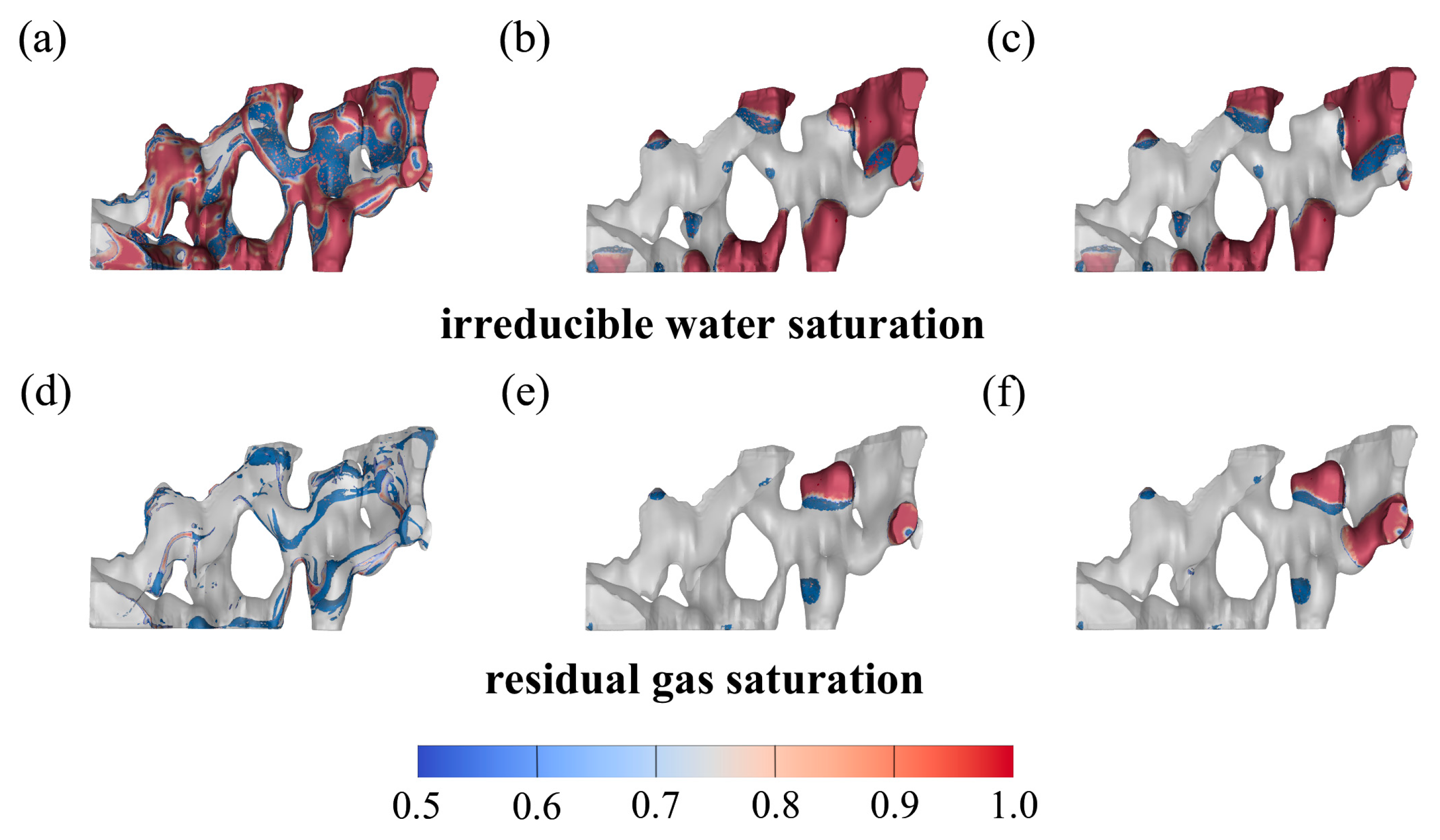
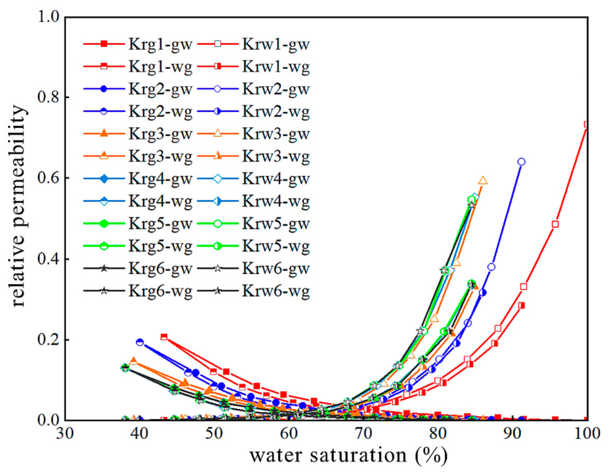
3. Results and Analysis

It can be found through the simulation results that the microscopic pore structure directly affects the fluid flow in the pore, which in turn affects the gas–water distribution. When gas is driven, the gas viscosity is much smaller than water, which makes it easy to form viscous fingering, and the injected gas will preferentially burst forward along the direction of the large pore channel to form an advantage channel, resulting in water in the tiny pores and dead-end pores that cannot be driven out of the core (Figure 3a–d), which forms irreducible water. With the increase in driving rounds, the blocked irreducible water gradually decreases. When water is driven, part of the gas is phase-dispersed due to gas adsorption and becomes residual gas adsorbed on the pore wall that cannot flow and cannot be extracted. The residual gas is mainly distributed in point and band form in the gas–water interface and blind-end pore space in the previous round (Figure 3e–h). With the increase in driving rounds, the gas continuity increases gradually and the residual gas increases gradually.
Irreducible water and residual gas saturation affect the reservoir capacity, so the effective reservoir capacity change rule can be found by observing the change in saturation in injection and extraction simulation under the driving rounds (Figure 4). The experiment shows that after 10 rounds of injection and extraction, the irreducible water saturation is reduced from 29.01% to 23.54%, which is about 5.47% lower, and in the process of one to four rounds of gas driving, the irreducible water saturation is reduced faster, totaling about 5% lower, accounting for 91.4% of the overall decrease in irreducible water saturation. The residual gas saturation increased from 2.42% to 3.73%, an increase of about 1.31%, and the reservoir capacity gradually increased, but this trend gradually slowed down in the late stages of injection and extraction operations.
Comparing the gas–water absolute permeability curves of different rounds of water–gas alternated flooding (Figure 5), it can be found that the water-phase permeability increases with the increase in replacement rounds, and the gas-phase permeability is almost unchanged. After several rounds of injection, the gas gradually affects the water film in the tiny pores and dead-end of the model, and the original unaffected water becomes an effective fluid participating in the seepage process, the water phase is gradually connected into a continuous phase, and the irreducible water is gradually reduced, which is conducive to the increase in the water-phase permeability.
In the process of water-driven gas, when most of the gas in the dominant pathway is discharged, the permeability of water and the water throughput capacity are greatly increased, with a water saturation of about 70% into an inflection point, because, at this point, the gas in the corners is difficult to discharge. By the same argument, there is a similar inflection point in water permeability during gas-driven water. Rocks have hydrophilic properties, resulting in the spreading of the water phase along the rock wall; the radius of the gas flow channel decreases with the increase in water saturation, and it is easy to create the Jiamin effect when the deformation of the pore occurs to cut off the gas, so the flow pore of the gas gradually decreases, the gas gradually loses the continuity to hinder the flow of the gas, and the residual gas gradually increases, meaning that the water saturation of the water in the bundle and the gas saturation of the gas in the residual increase.

4. Analysis of Influencing Factors

Based on the analysis of microscopic distribution state and formation mechanisms, simulation under different injection and extraction conditions can be carried out to provide guidance for gas reservoir injection and extraction operations.

4.1. Improvement in Injection Intensity

There is a strong sensitivity between the irreducible water saturation and the injection rate in the experiment [9,35], and the gas–water distribution of the model after four rounds of injection operation under different injection rates is given in Figure 6, from which it can be found that increasing the injection intensity can enhance the ability of the repellent phase to overcome the capillary resistance at the pore throats, and, therefore, the seepage capacity in the connected large pores is enhanced, and the irreducible water in the connected pore throats can be better repelled. At the end of the injection operation, the saturation rates of the irreducible water with injection rates of 0.2, 0.3, and 0.4 m/s were 24%, 23.7%, and 22%, respectively, and the saturation rates of the residual gas were 3.3%, 3.1%, and 2.8%, respectively, i.e., the reservoir capacity was also increasing, due to an increase in the injection intensity.

4.2. Increasing the Reservoir Pressure

Under the same driving conditions, the microscopic flow simulation results under the simulated pressures of 5 MPa, 10 MPa, and 15 MPa are shown in Figure 7. Under the simulation condition of 80 degrees Celsius, methane gas changes from water vapor to a supercritical state starting from 4.6 MPa; at the same time, the density and viscosity of methane increase with the increasing pressure, and we reflect this physical property change by fitting the curves of density and viscosity to pressure in our simulation. This results in the saturation rates of the irreducible water being 24%, 33.9%, and 30.3%, and the saturation rates of the residual gas being 3.3%, 4.1%, and 5.7%. Due to the pressure increase, the gas viscosity and density increase, and the interfacial tension decreases, meaning that the injection and extraction is difficult to carry out in the dead-end pore near the edge. As a result, the irreducible water and residual gas are no longer distributed in the pore wall in the form of bands, but are concentrated in the dead-end pore. During the actual injection and extraction operation, the storage capacity can be increased by appropriately reducing the reservoir pressure.

5. Discussion

Current research on the mechanisms of gas–water seepage in gas reservoirs is still mainly based on experiments. We visualized the water–gas alternated flooding process by performing a fluid simulation on digital cores, and we found that irreducible water decreases and residual gas increases with the increase in alternated flooding rounds. This finding is inconsistent with the experimental content of some articles.
In previous studies, the conclusions about the changes in irreducible water and residual gas saturation with alternated flooding rounds are mainly divided into two categories, one of which is the same as the conclusion of this paper [36,37], i.e., with the increase in alternated flooding rounds, the irreducible water decreases and residual gas increases, while the other group believes that both irreducible water and residual gas decrease with increasing alternated flooding rounds [14,38]. A comparison shows that the different conclusions may be due to different experimental environments; the experiments with the same conclusions as in this paper applied higher confining pressures to the cores to simulate the reservoir environment. To ensure the rigor of the article, we carried out water–gas alternated flooding experiments on the original size samples, wherein the experimental confining pressure and temperature were set to the real reservoir pressure and temperature. The trends presented in the experimental results are consistent with those presented in the simulation results. The experimental results and the permeability saturation curve during the experiment are shown in Figure 8 and Figure 9, respectively.
Several limitations of this investigation suggest promising directions for future research. First, due to the lack of computing power, only the pore scale can be simulated, and the mechanism of fluid seepage in complex pore structures is unknown.
Second, edge water intrusion into the reservoir can cause reservoir injury and lead to the loss of gas injection, but the method in this paper cannot simulate this change. Future research may be able to train an artificial intelligence model and thus predict fatigue cracking.

6. Conclusions

Firstly, combining digital core technology and two-phase microscopic seepage simulation can lead to a reproduction of the microscopic driving process in a real reservoir pore space. This study provides ideas and technical support for the application of digital core technology in microscopic seepage in aquifer reservoirs.
Secondly, with an increase in water–gas alternated flooding rounds, the irreducible water saturation of the reservoir pore model decreases dramatically, the residual gas saturation increases, and the effective reservoir capacity increases. The irreducible water is mainly distributed in the tiny pores and dead-end pores, and the residual gas is mainly distributed in the gas–water interface and dead-end pores in the previous round in the form of points and bands.
Thirdly, increasing the intensity of alternated flooding can accelerate the transportation speed of the gas–water interface and increase the expansion speed of the reservoir; appropriately lowering the reservoir pressure reduces the viscosity and density of the gas and increases the gas reach, thus increasing the effective reservoir capacity.

Author Contributions

Methodology, Z.Y.; Avizo-20201, Z.Z.; Writing—original draft, Z.Z.; Writing—review & editing, Z.Z. All authors have read and agreed to the published version of the manuscript.

Funding

This research was funded by the Heilongjiang Provincial Key R&D Program Projects grant number (GA23A914).

Data Availability Statement

The original contributions presented in the study are included in the article, further inquiries can be directed to the corresponding author/s.

Conflicts of Interest

The authors declare no conflict of interest.

References

  1. Gao, Y.; Wang, B.; Hu, Y.; Gao, Y.; Hu, A. Development of China’s natural gas: Review 2023 and outlook 2024. Nat. Gas Ind. 2024, 44, 166–177. [Google Scholar]
  2. Zhou, Y.; Ye, J.; Yu, S.; Zhao, L.; Wang, Y.; Zhu, S.; Deng, L.; Duan, Y. Development status and opportunities of natural gas distributed energy resource under the goal of “dual carbon”. Nat. Gas Ind. 2024, 44, 23–29. [Google Scholar]
  3. Zou, C.; Li, M.; Ma, F.; Liu, H.; Yang, Z.; Zhang, G.; Yang, Y.; Guan, C.; Liang, Y.; Wang, Y.; et al. Development, challenges and strategies of natural gas industry under carbon neutral target in China. Pet. Explor. Dev. 2024, 51, 418–435. [Google Scholar] [CrossRef]
  4. Li, Q.; Cheng, Y.; Li, Q.; Zhang, C.; Ansari, U.; Song, B. Establishment and evaluation of strength criterion for clayey silt hydrate-bearing sediments. Energy Sources Part A Recovery Util. Environ. Eff. 2018, 40, 742–750. [Google Scholar] [CrossRef]
  5. Li, Q.; Wang, Y.; Wang, F.; Wu, J.; Tahir, M.U.; Li, Q.; Yuan, L.; Liu, Z. Effect of thickener and reservoir parameters on the filtration property of CO2 fracturing fluid. Energy Sources Part A Recovery Util. Environ. Eff. 2020, 42, 1705–1715. [Google Scholar] [CrossRef]
  6. Li, Z.; Hatzignatiou, D.G.; Ehlig-Economides, C. Carbon Dioxide Storage in a Natural Gas Reservoir under Strong Bottom Water Drive. In Proceedings of the SPE/AAPG/SEG Carbon, Capture, Utilization, and Storage Conference and Exhibition, Houston, TX, USA, 11–13 March 2024. [Google Scholar]
  7. Denney, D. Relative Permeability Hysteresis: Water-Alternating-Gas Injection and Gas Storage. J. Pet. Technol. 2013, 65, 90–92. [Google Scholar] [CrossRef]
  8. Shen, M.; Han, G.; Liu, H.; Cui, S. Design of Test Platform for Coupling Field of Rock Stress and Seepage in Underground Storage Cavern. In Proceedings of the ISRM Regional Symposium—11th Asian Rock Mechanics Symposium, Beijing, China, 21–25 October 2021. [Google Scholar]
  9. Jiang, T.; Qi, H.; Wang, Z.; Li, Y.; Wang, J.; Liu, Z.; Cao, J. Microscopic simulation experiment on efficient construction of underground gas storages converted from water-invaded gas reservoirs. Pet. Explor. Dev. 2024, 51, 182–189. [Google Scholar] [CrossRef]
  10. Li, D.W.; Zhang, L.H.; Zhou, K.M.; Guo, L.P. Gas-water two-phase flow mechanism in visualmicroscopic pore model. J. China Univ. Pet. 2008, 32, 80–83. [Google Scholar]
  11. Bai, M.; Qin, F.; Hong, S.; Yang, P.; Chen, S. Study on micro seepage characteristics of gas and water in marine sandstone water drive gas reservoirs. Petrochem. Ind. Appl. 2023, 42, 71–75. [Google Scholar]
  12. Gao, J.; Kong, D.; Peng, Y.; Zhou, Y.; Liu, Y.; Zhu, W. Seepage law of gas-reservoir UGSs during multi-cycle injection and production. Nat. Gas Ind. 2023, 43, 103–111. [Google Scholar]
  13. Li, C.; Wang, J.; Xu, H.; Tang, L.; Sun, C. Study on Fluids Flow Characteristics of Water-Gas Mutual Flooding in Sandstone Underground Gas Storage with Edge Water. In Proceedings of the International Petroleum Technology Conference, Beijing, China, 26 March 2013. [Google Scholar]
  14. Zhang, M.; Duan, Y.; He, J.; Meng, L.; Liang, T.; Bai, H.; Zhou, F. Dynamic Characterization of Water Blockage During Water-Gas Alternated Flooding in the Underground Gas Storage. In Proceedings of the 56th US Rock Mechanics/Geomechanics Symposium, Santa Fe, NM, USA, 26–29 June 2022. [Google Scholar]
  15. Fatemi, S.M.; Sohrabi, M. Experimental and Theoretical Investigation of Water/Gas Relative Permeability Hysteresis: Applicable to Water Alternating Gas (WAG) Injection and Gas Storage Processes. In Proceedings of the Abu Dhabi International Petroleum Conference and Exhibition, Abu Dhabi, United Arab Emirates, 11–14 November 2012. [Google Scholar]
  16. Egermann, P.; Schaaf, T.; Bréfort, B. A Modified Hysteresis Relative Permeability Including a Gas Remobilization Threshold For Better Production Forecasts of Gas Storages. Petrophysics SPWLA J. Form. Eval. Reserv. Descr. 2010, 51. [Google Scholar] [CrossRef]
  17. Barbosa Machado, M.V.; Delshad, M.; Sepehrnoori, K. A Practical and Innovative Workflow to Support the Numerical Simulation of CO2 Storage in Large Field-Scale Models. SPE Reserv. Eval. Eng. 2023, 26, 1541–1552. [Google Scholar] [CrossRef]
  18. Du, M.; Yang, Z.; Jiang, E.; Lv, J.; Yang, T.; Wang, W.; Wang, J.; Zhang, Y.; Li, H.; Xu, Y. Using digital cores and nuclear magnetic resonance to study pore-fracture structure and fluid mobility in tight volcanic rock reservoirs. J. Asian Earth Sci. 2024, 259, 105890. [Google Scholar] [CrossRef]
  19. Yu, Y.; Jia, X.; Cheng, W.; Cui, W.; Xing, H.; Rui, J. Seepage Evolution Law of Coal during Loading Process Based on Digital Core. J. Energy Eng. 2024, 150, 04024004. [Google Scholar] [CrossRef]
  20. Zhang, D.; Hu, H.; Dong, Y.; Wang, Y.; Liu, D.; Liu, H.; Du, M. Seepage Simulation of Conglomerate Reservoir Based on Digital Core: A Case Study of the Baikouquan Formation in Mahu Sag, Junggar Basin. Processes 2023, 11, 3185. [Google Scholar] [CrossRef]
  21. Morrison, G. A Digital Core Laboratory Characterising Oil Water Transition Zones. In Proceedings of the SPE Asia Pacific Oil & Gas Conference and Exhibition, Virtual, 12 November 2020. [Google Scholar]
  22. Zhu, Y.; Tao, G.; Fang, W.; Xu, X. Lattice Boltzmann Simulation of Permeability in3D Porous Medium. Well Logging Technol. 2008, 32, 25–28. [Google Scholar]
  23. Wang, H.; Su, Y.; Wang, W.; Li, G.; Zhang, Q. Simulation on liquid flow in shale nanoporous media based on latice Boltzmann method. Acta Pet. Sin. 2023, 44, 534–544. [Google Scholar]
  24. Olhin, A.; Vishnyakov, A. Pore Structure and Permeability of Tight-Pore Sandstones: Quantitative Test of the Lattice–Boltzmann Method. Appl. Sci. 2023, 13, 9112. [Google Scholar] [CrossRef]
  25. Sha, B.; Jia, Z. A very robust MMALE method based on a novel VoF method for two-dimensional compressible fluid flows. Comput. Math. Appl. 2024, 160, 86–107. [Google Scholar] [CrossRef]
  26. Yang, Y.; Wang, J.; Wang, J.; Zhang, Q.; Yao, J. Pore-scale numerical simulation of supercritical CO2-brine two-phase flow based on VOF method. Nat. Gas Ind. B 2023, 10, 466–475. [Google Scholar] [CrossRef]
  27. Song, R.; Sun, S.; Liu, J.; Yang, C. Pore scale modeling on dissociation and transportation of methane hydrate in porous sediments. Energy 2021, 237, 121630. [Google Scholar] [CrossRef]
  28. Fontanesi, S.; Olcuire, M.; Cicalese, G.; Lamberti, L.; Pulvirenti, F.; Berni, F. Computational Fluid Dynamics (CFD) Analysis of Lubricant Oil Tank Sloshing of a High-Performance Car under Racetrack Maneuvers. SAE Int. J. Engines 2021, 15, 1–17. [Google Scholar] [CrossRef] [PubMed]
  29. Yang, Y.; Xu, Q.; Li, X.; Zhang, L.; Lan, X.; Wang, J.; Yao, J. Pore-scale simulation of gas-water two-phase flow in volcanic gas reservoir based on Volume of Fluid method. J. Nat. Gas Sci. Eng. 2022, 106, 104733. [Google Scholar] [CrossRef]
  30. Yang, Y.; Cai, S.; Yao, J.; Zhong, J.; Zhang, K.; Song, W.; Zhang, L.; Sun, H.; Lisitsa, V. Pore-scale simulation of remaining oil distribution in 3D porous media affected by wettability and capillarity based on Volume of Fluid method. Int. J. Multiph. Flow 2021, 143, 103746. [Google Scholar] [CrossRef]
  31. Zhang, Z.; Krishnan, P.; Jiao, Z.; Mannan, M.S.; Wang, Q. Developing a CFD heat transfer model for applying high expansion foam in an LNG spill. J. Loss Prev. Process Ind. 2021, 71, 104456. [Google Scholar] [CrossRef]
  32. Chung, M.S.; Kim, J.W. A Numerical Modelling of Two-Phase Flow System. In Proceedings of the ASME 2008 International Design Engineering Technical Conferences and Computers and Information in Engineering Conference, Brooklyn, NY, USA, 3–6 August 2008. [Google Scholar]
  33. Tryggvason, G.; Scardovelli, R.; Zaleski, S. Direct Numerical Simulations of Gas–Liquid Multiphase Flows: Frontmatter; Cambridge University Press: Cambridge, UK, 2011. [Google Scholar]
  34. Brackbill, J.U.; Kothe, D.B.; Zemach, C. A continuum method for modeling surface tension. J. Comput. Phys. 1992, 100, 335–354. [Google Scholar] [CrossRef]
  35. Sun, Y.; He, H.; Zhong, X.; Jia, Q.; Hu, C.; Li, C. Study on the microscopic seepage mechanism of modified gas storage reservoirs in water injection development reservoirs. China Pet. Chem. Stand. Qual. 2021, 41, 120–121. [Google Scholar]
  36. He, X.; Huang, S.; Sun, C.; Xu, J.; Zhang, X.; Yang, X. Gas-water relative permeability variation in multi-cycle injection- production of underground gas storage in flooded depleted gas reservoir. Oil Gas Storage Transp. 2015, 34, 150–153. [Google Scholar]
  37. Wang, J.; Guo, P.; Jiang, F. The physical simulation study on the gas-drive multiphase flow mechanism of aquifer gas storage. Nat. Gas Geosci. 2006, 17, 597–600. [Google Scholar]
  38. Chen, Y.; Li, X.; Li, S. A dynamic prediction method for the ground surface deformation of concentrated storage groups based on time-de- pendent convergence characteristics of salt caverns. Nat. Gas Ind. 2012, 32, 85–87+135–136. [Google Scholar]
Figure 1. Digital core creation based on CT scans.
Energies 17 04149 g001
Figure 2. Pore mesh of the representation unit.
Energies 17 04149 g002
Figure 3. (ad) show the distribution of irreducible water under the 2nd, 3rd, 6th, and 10th rounds in the gas-driven water process, and (eh) show the distribution of residual gas under the same rounds in the water-driven gas process.
Energies 17 04149 g003
Figure 4. Saturation changes under multiple rounds of water–gas alternated flooding.
Energies 17 04149 g004
Figure 5. Gas−water absolute permeability curves of different rounds of water−gas alternated flooding.
Energies 17 04149 g005
Figure 6. (ac) show the distribution of irreducible water at the injection speeds of 0.2 m/s, 0.3 m/s, and 0.4 m/s during the gas-driven water drive process, and (df) show the distribution of residual gas at the corresponding injection speeds during the water-driven gas drive process.
Energies 17 04149 g006
Figure 7. (ac) show the distribution of irreducible water at 5 MPa, 10 MPa, and 15 MPa in the gas-driven water process, and (df) show the distribution of residual gas at the corresponding pressures in the water-driven gas process.
Energies 17 04149 g007
Figure 8. Saturation changes under multiple rounds of water–gas alternated flooding rounds in the experiment.
Energies 17 04149 g008
Figure 9. Water permeability saturation curves during experiments.
Energies 17 04149 g009
Table 1. Basic pore structure parameters of digital cores.
Statistics TypeValue
Permeability ( 10 3 μm2)23.4
Porosity (%)15.2
Number of pores529
Number of throats976
Equivalent pore diameter ( μ m )23.4
Equivalent throat diameters ( μ m )5.9
Average throat length ( μ m )92.4
Average coordination number6.2
Disclaimer/Publisher’s Note: The statements, opinions and data contained in all publications are solely those of the individual author(s) and contributor(s) and not of MDPI and/or the editor(s). MDPI and/or the editor(s) disclaim responsibility for any injury to people or property resulting from any ideas, methods, instructions or products referred to in the content.

