Article

Storage Regulation Mechanism and Control Strategy of a Hydraulic Wave Power Generation System

by
Jianjun Peng
1,2,*,
Chenchen Huang
1,
Meng Xue
1,
Run Feng
1,
Erhao Zhou
1,
Zhidan Zhong
1,2 and
Xiangchen Ku
1,2,*
1
School of Mechanical and Electrical Engineering, Henan University of Science and Technology, Luoyang 471003, China
2
Collaborative Innovation Center of Henan Province for High-End Bearing, Luoyang 471003, China
*
Authors to whom correspondence should be addressed.
Energies 2024, 17(16), 4151; https://doi.org/10.3390/en17164151
Submission received: 17 July 2024 / Revised: 9 August 2024 / Accepted: 15 August 2024 / Published: 21 August 2024

Abstract

:
Based on a mechanism study, the regulation and control mechanism of the hydraulic energy storage system is elaborated in detail, and the regulation and control strategy is formulated for the hydraulic power generation system under the condition of a stable random wave, and the working mode of the wave power generation system is deeply studied. According to the characteristics of a hydraulic system, a control strategy of a three-position four-way electromagnetic directional valve suitable for adaptive energy storage system is proposed. In order to verify the feasibility of the control strategy, a mathematical model of the hydraulic cylinder displacement control system is designed based on the Matlab/Simulink platform, and a PID control strategy is introduced to build a wave simulation loop. Amesim and Simulink co-simulation is used to verify the performance of the wave simulation circuit and the hydraulic power generation system. The simulation results show that the maximum error rate is only 0.8% after PID control is added to the wave power generation simulation loop, the displacement of the hydraulic cylinder can reach the expected value, and the random wave motion can be simulated effectively. In the hydraulic system of wave energy generation, the proposed adaptive control strategy can accelerate the system stability process, reduce the power overshoot significantly, and convert wave energy into electric energy more effectively.

1. Introduction

Renewable energy development is a global imperative and an essential direction for the sustainable advancement of human society. Among the various renewable energy sources, wave energy has garnered considerable research and development attention within the marine renewable energy sector owing to its high energy density, wide-spread distribution, and ease of harvesting. Consequently, the extent and scale of its application have emerged as significant indicators of a country’s progress in the field of new energy science and technology [1,2].
Wave energy harvesting devices typically rely on direct-drive, pneumatic, or hydraulic energy conversion techniques. Among these, hydraulic techniques, offering distinct advantages, are predominantly employed as energy conversion systems in contemporary wave energy harvesting devices. Furthermore, hydraulic systems equipped with accumulators are known to smoothen the power generation process and effectively address stability issues in the energy output [3,4,5,6,7]. Relevant examples of such systems include the PowerBuoy series, Pelamis, Oyster, the eagle wave energy converter developed by the Guangzhou Energy Research Institute, and the double-stroke buoyancy pendulum introduced by Zhejiang University [8]. Notably, contemporary wave energy harvesting devices can be categorized into the following two groups based on their operating principles: wave energy capture systems and energy conversion systems, which convert mechanical energy into electrical energy. Both systems have been extensively investigated by scholars. For instance, Changhai et al. [9] designed a hydraulic drive system capable of mimicking real-time float movements under wave influence, thus obviating the need for laboratory pools or sea trials. This system also enables the performance testing of the power generation system even before its deployment. Furthermore, Qijuan et al. [10] examined a resonance wave energy harvesting device, utilizing a proportional speed control valve to regulate the speed of its hydraulic cylinder, thus successfully replicating actual wave motion to drive the hydraulic cylinder. Lian, J. et al. [11] classified wave energy converters emerge and summarized the generation power, and energy conversion efficiency of various devices and some shortcomings and suggestions were put forward. Negri, M. et al. [12] identified the problem of wave energy conversion in shallow water analyzed the performance of two different oscillating-body systems, and found that the system obtained by coupling the heaving float with a surging paddle has a significant advantage over the heaving float system in shallow water. Sakr, A.H. et al. [13] proposed a new short-term reactive loading control technique for heaving buoy wave energy converters (WECs) that maximizes power absorption. Ramezanzadeh, S. et al. [14] conducted a study on the geometry effects over the performance of oscillating water column (OWC)-type wave energy converter (WEC) systems and proposed that this geometry shows better performance with respect to base geometry results in all wave conditions. Simonetti, I. et al. [15] presented a hybrid wave energy converter concept, the O2WC (Oscillating–Overtopping Water Column) device. Through laboratory tests, the results showed that the decrease in the primary conversion efficiency of the OWC component of the device caused by the decreased air pressure in the OWC chamber can be partially compensated by the additional energy stored in the overtopping chamber of the O2WC device. Yin et al. [16] mathematically modeled the hydraulic energy conversion system of a wave energy harvesting device, encompassing an energy storage and pressure stabilization link, along with an autonomous hydraulic controller. The accuracy of the developed system simulation model was verified through experiments. Meanwhile, Wenjie et al. [17] aimed to improve the efficiency of hydraulic-to-electric energy conversion in an accumulator-based wave power generation system. Specifically, they designed a physical test model of the energy storage and electric power system, ultimately observing that reducing the initial pressure of the accumulator while simultaneously increasing the release pressure of the power generation system could enhance its power generation efficiency. Zhenpeng et al. [18] employed a hydraulic control system with autonomous functionalities in the “Wanshan” eagle device. Sea tests revealed that the generator set, equipped with an autonomous control module for energy storage and centralized power generation, maintained stable output voltage and current performance, achieving an energy conversion efficiency exceeding 80%. Chen et al. [19] optimized the inflation pressure of a bladder accumulator to approximately 90% of its rated pressure, while Yaqun et al. [20] investigated the hydraulic energy conversion system of a floating wave energy device, demonstrating a coupling relationship between the amount of energy stored and the maximum operating pressure, minimum operating pressure, and precharge pressure.
As can be seen from the above, most studies have been conducted separately on these two parts, and there are few overall studies on wave energy simulation and generation. Therefore, in order to solve the problem that the hydraulic power generation system under stable and random wave conditions can generate electricity continuously and statically, this study built a wave simulation loop and developed regulation and control strategies. It can provide some reference and theoretical guidance for the development and utilization of marine renewable energy such as wave energy and tidal current energy.

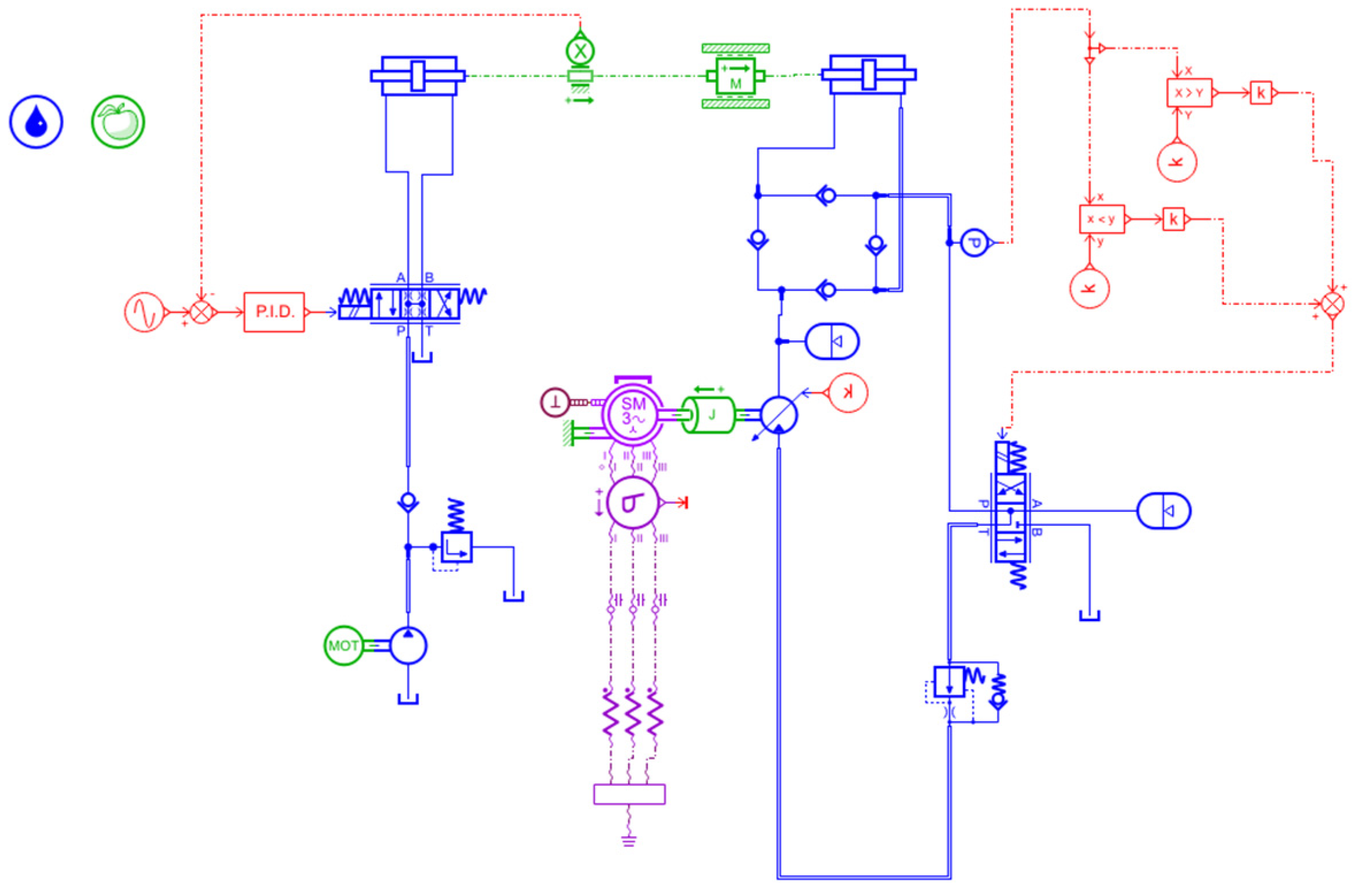
2. Working Principle of the Hydraulic Wave Power Generation System

Complex wave–current interactions exist in the ocean, involving shear generation, momentum transfer, and turbulent mixing, characterized by significant stochasticity [21]. To investigate the regulation mechanism and control strategy of a hydraulic wave power generation system under both smooth and random wave conditions, we developed an accumulator-based hydraulic wave power generation system comprising two primary components. Among these, the first component is dedicated to the simulation of real-time wave motion under random wave conditions. For this, the module is equipped with a hydraulic pump driven by a variable frequency motor, drawing oil from a hydraulic oil tank to generate pressurized oil. This oil is then discharged to a three-position four-way directional control valve, regulating its flow and inducing random motion of the double-acting piston hydraulic cylinder 1. The second part comprises the hydraulic wave power generation system. Here, under a constant supply of hydraulic energy from double-acting hydraulic cylinder 1, double-acting hydraulic cylinder 2 increases the pressure of accumulator 1. Upon reaching a predetermined pressure threshold, the three-position four-way directional control valve and proportional speed control valve open, initiating the rotation of the variable hydraulic motor. This rotation converts hydraulic energy into mechanical energy, which, in turn, drives the permanent magnet synchronous generator to produce electrical energy [22,23,24]. Accumulator 14 is a low-pressure accumulator designed to store additional hydraulic energy in the system, aimed at mitigating the instability of wave energy in wave power generation systems, thereby ensuring system stability and continuity. Figure 1 depicts a schematic of the hydraulic wave power generation system.

3. Mathematical Modeling of Wave Simulation Loops

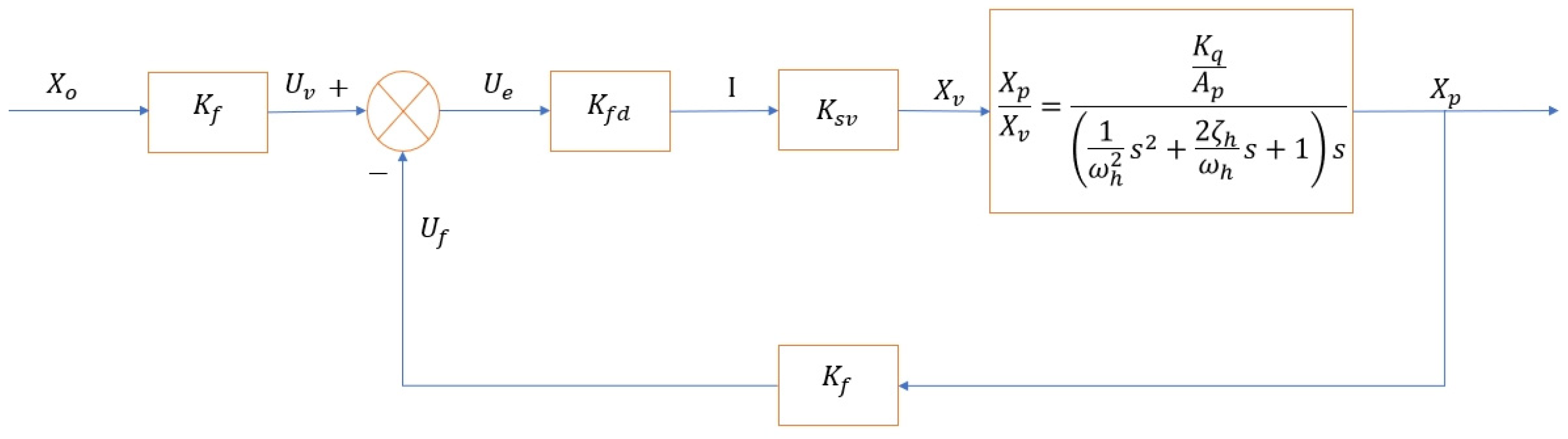
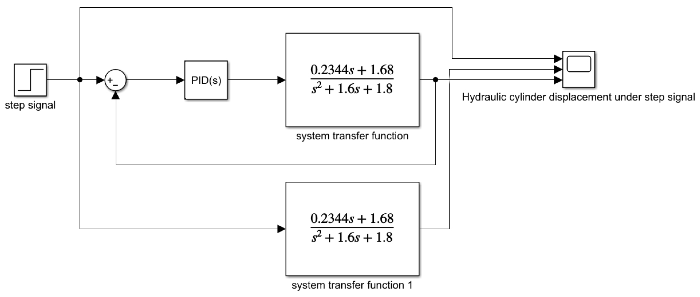
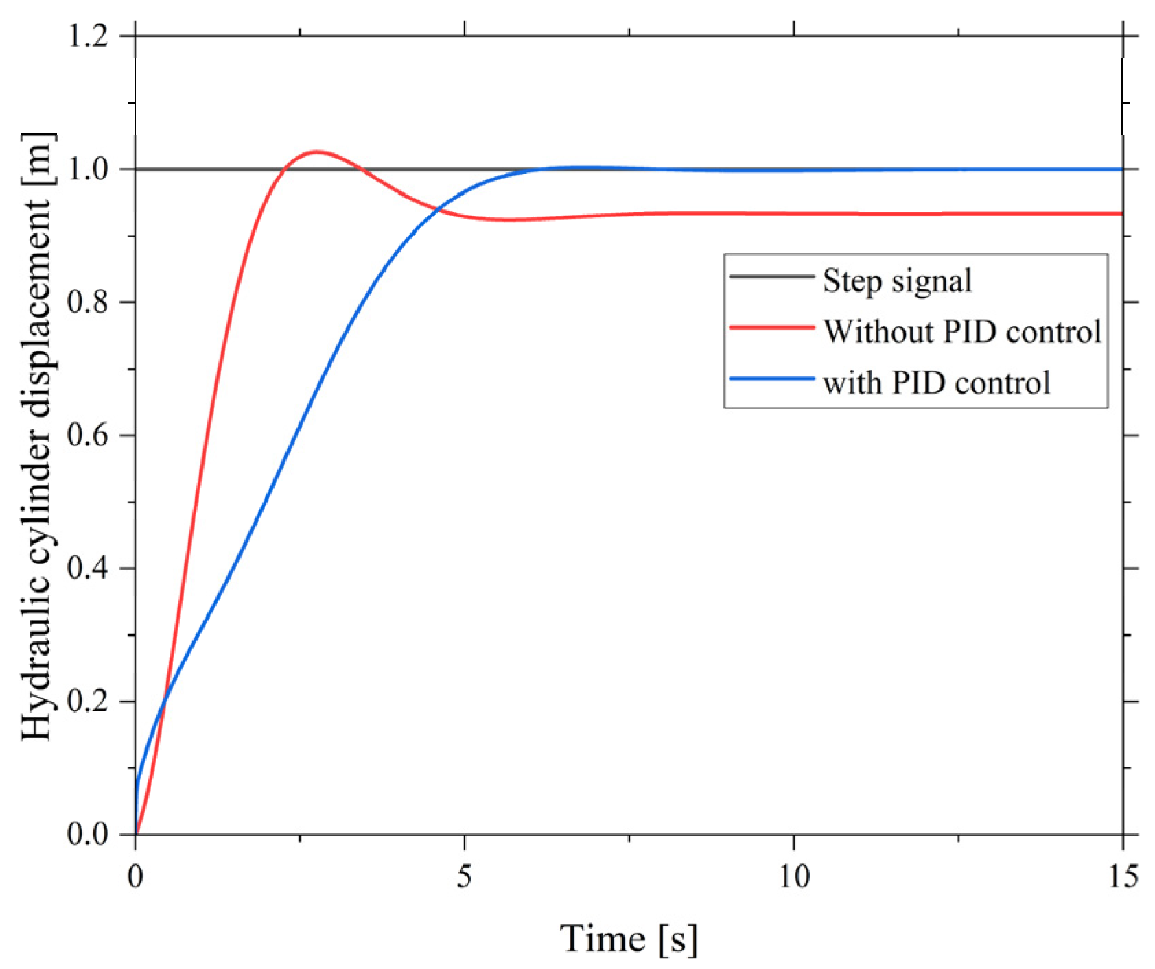
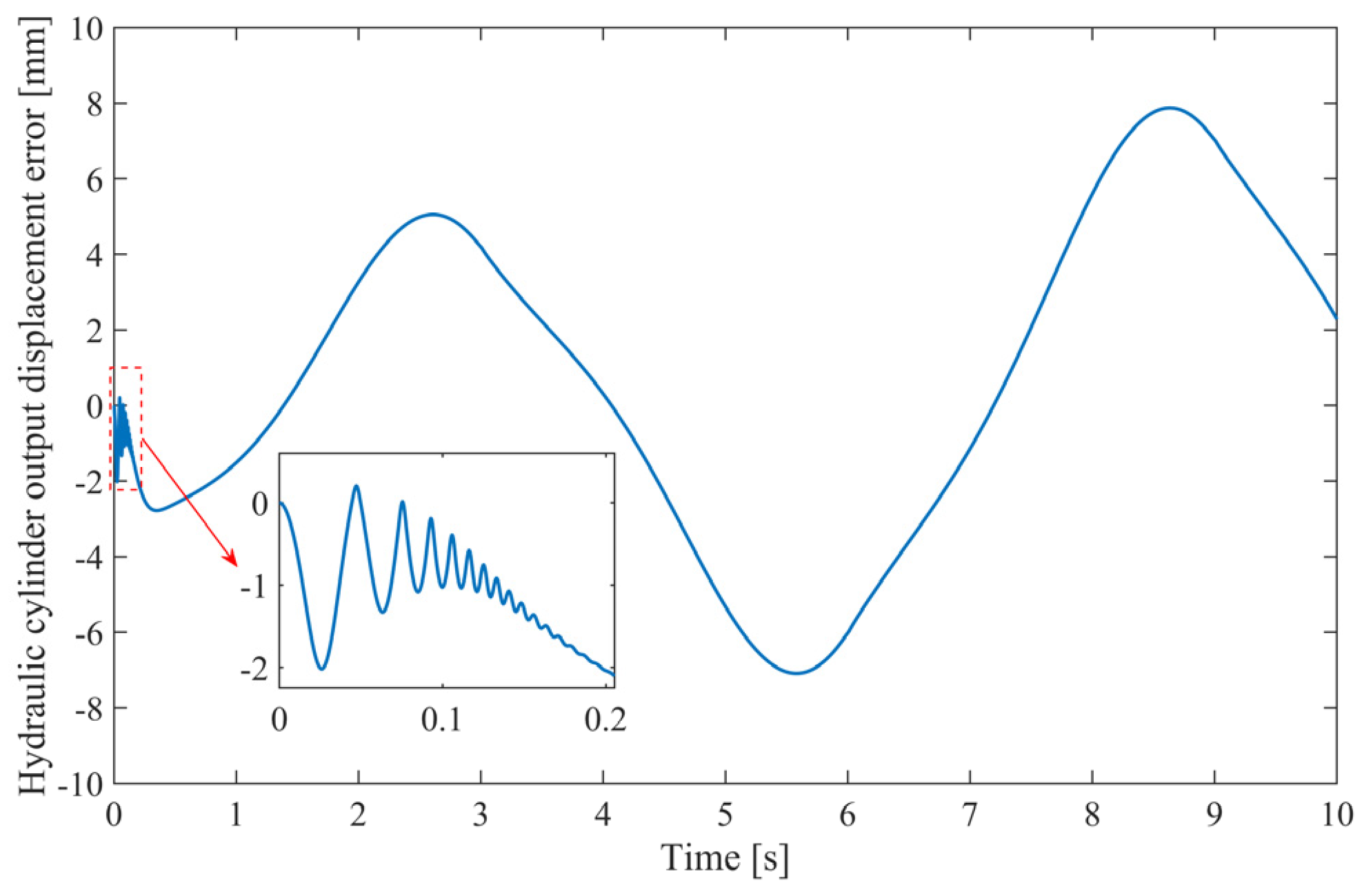
3.1. Establishing a Mathematical Model for the Hydraulic Cylinder Displacement Control System

To enhance the accuracy of wave motion simulation, we developed a mathematical model of the hydraulic cylinder displacement control system. For this, we obtained the transfer function of the system through system identification and established the mathematical model of the valve-controlled cylinder by leveraging modern control theory. Furthermore, we controlled the displacement of the hydraulic cylinder and the motor volume by employing the inverse-step method (nonlinear control) and feedback linearization method. To verify the accuracy of the model, we conducted joint simulations using both Amesim and Simulink. Figure 2 presents a schematic depicting the control signals within the wave simulation loop.
The following expressions present the transfer functions of the components of the hydraulic wave power generation system:
1.
First, the transfer function of the valve-controlled cylinder is expressed as
X p X v = K q A p ( 1 ω h 2 s 2 + 2 ζ h ω h s + 1 ) s
where K q denotes the velocity gain, A p represents the piston effective area, ω h indicates the natural frequency of the hydraulic system, and ζ h represents the damping ratio of the hydraulic system.
2.
Next, the transfer function of the servo valve is expressed as
G s v = K s v = X v m a x I
where I denotes the input current, and X v m a x represents the maximum spool displacement.
3.
Moving further, the transfer function of the servo amplifier is expressed as
K f d = I U e
where I denotes the input current, and U e represents the offset voltage.
4.
Finally, the transfer function of the displacement sensor is modeled as
K f = U f X p
where U f denotes the feedback voltage signal, and X p represents the real-time running displacement of the hydraulic cylinder.
The above transfer functions were integrated into a complete system, yielding the overall block diagram of the complete system, as depicted in Figure 3.
The model was then simplified to a second-order system using MATLAB 2021 for system identification, yielding the following transfer function:
0.2344 s + 1.68 s 2 + 1.6 s + 1.8
Subsequently, the model was constructed in Simulink, as depicted in Figure 4.
Figure 5 and Figure 6 depict the step and sinusoidal responses of the system, respectively.
Figure 5 reveals an overshoot in the system response. Furthermore, the consistency between the displacement of the hydraulic cylinder under a sinusoidal signal and the corresponding simulation result, as depicted in Figure 6 and Figure 7, respectively, corroborates the accuracy of the second-order transfer function model.
In order to verify the stability of the control system, the model shown in Figure 8 was built in Simulink:
The response of the control system under step signal and the response curve of the system with or without PID control can be obtained, as shown in Figure 9.
When evaluating the motion stability of the hydraulic cylinder, it can generally be considered from the error index, oscillation and vibration, steady-state error and energy consumption, and other indicators, and the following were analyzed for these aspects. It can be seen from Figure 8 that there is a large overshoot in the control system without PID control, and a part of the energy consumption is lost in this process, resulting in the actual position of the hydraulic cylinder and the target position of about 8% deviation. After adding the PID control strategy to the control system, it can be seen that the overshoot of the control system is significantly reduced, the energy consumption is reduced, the actual position of the hydraulic cylinder is almost coincident with the target position, the steady-state error is reduced, and there is almost no shock. From the above analysis, it can be concluded that PID control can ensure the stability of the system under various operating conditions and achieve the best balance between dynamic response and steady-state performance.

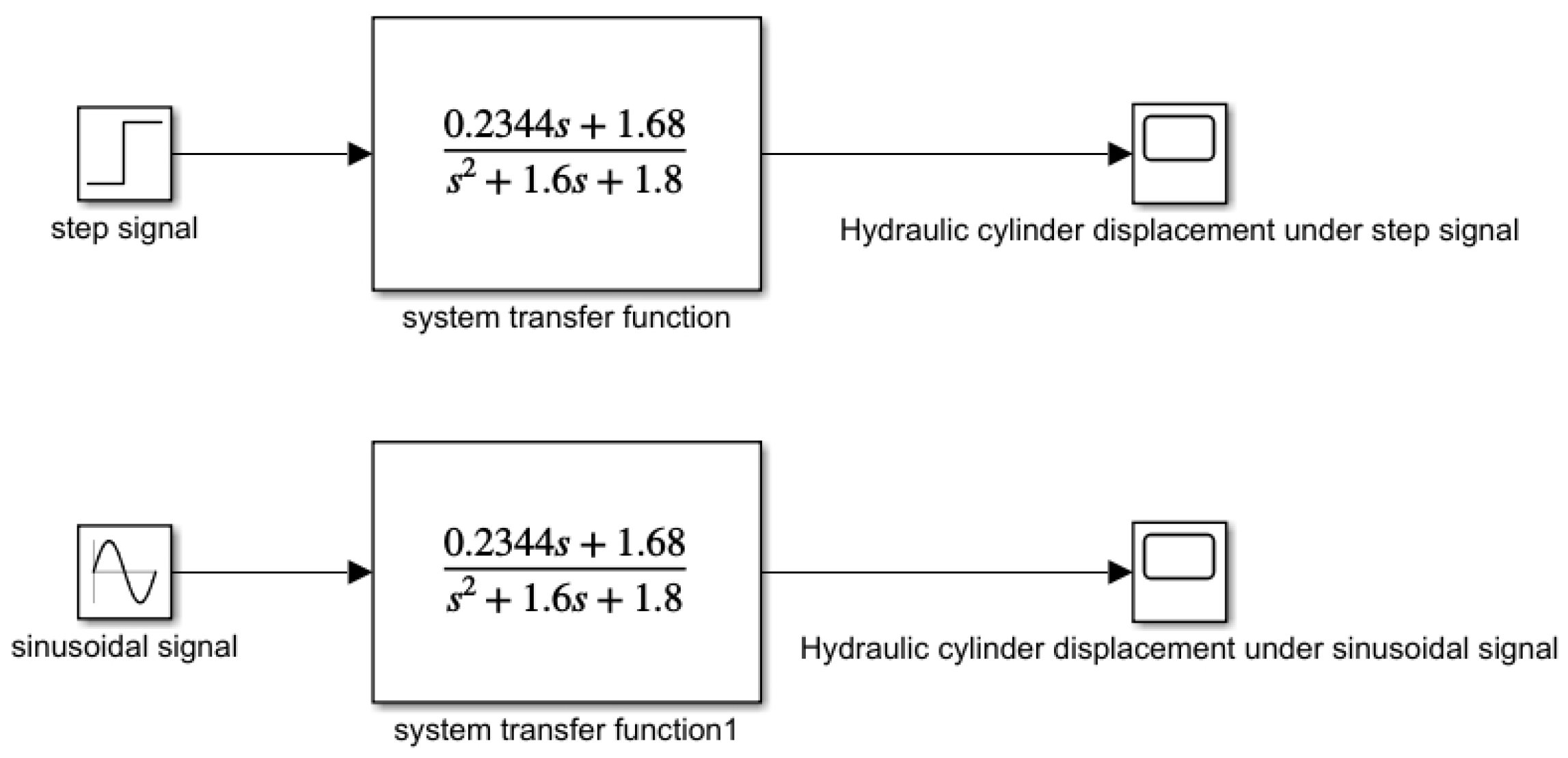
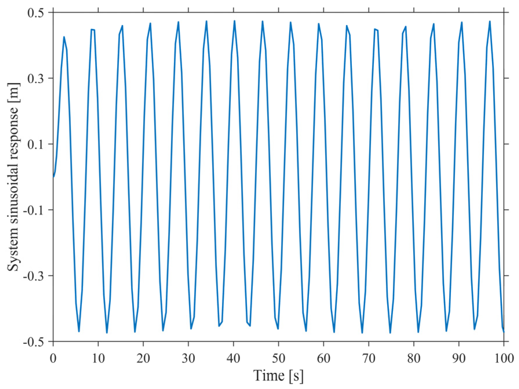
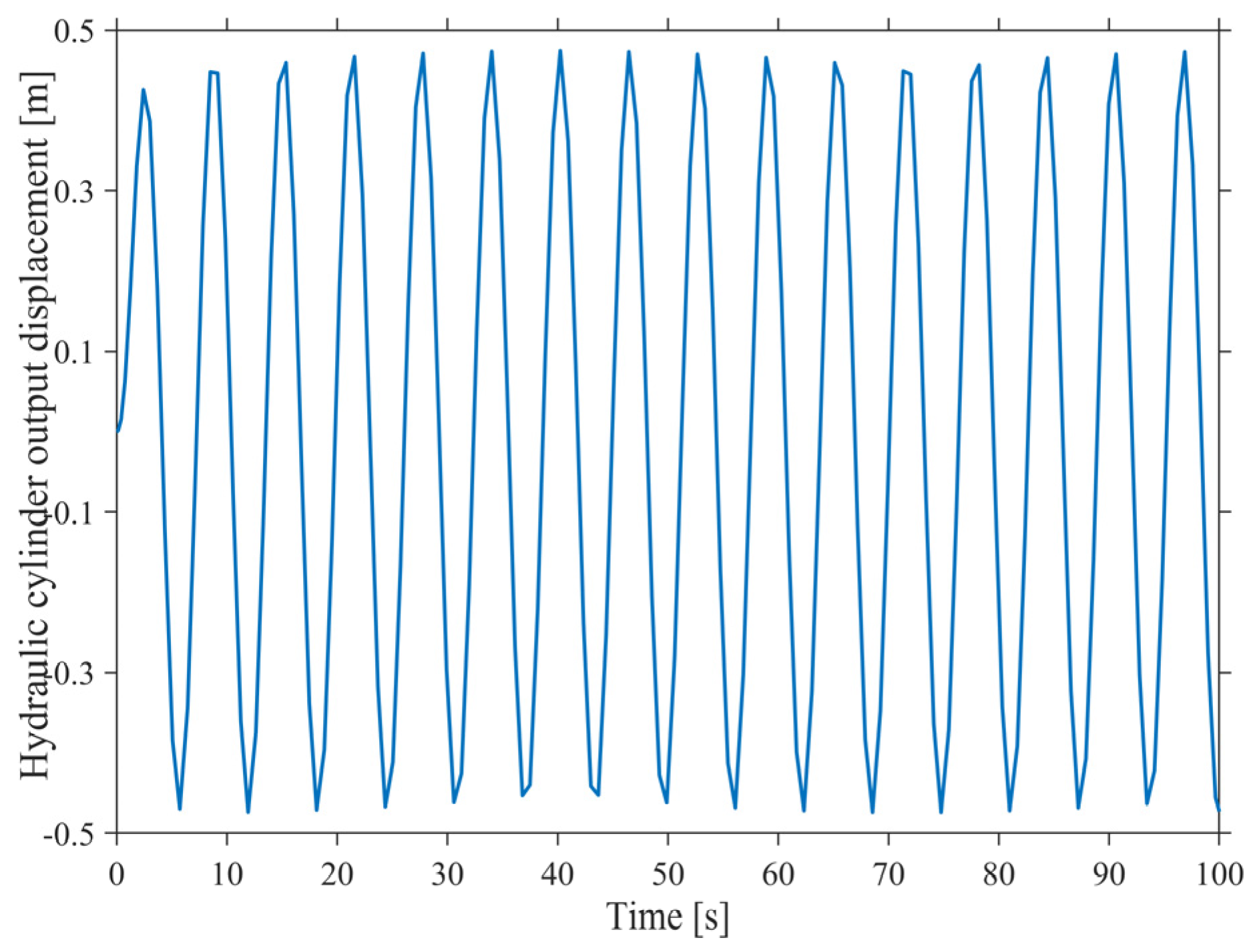
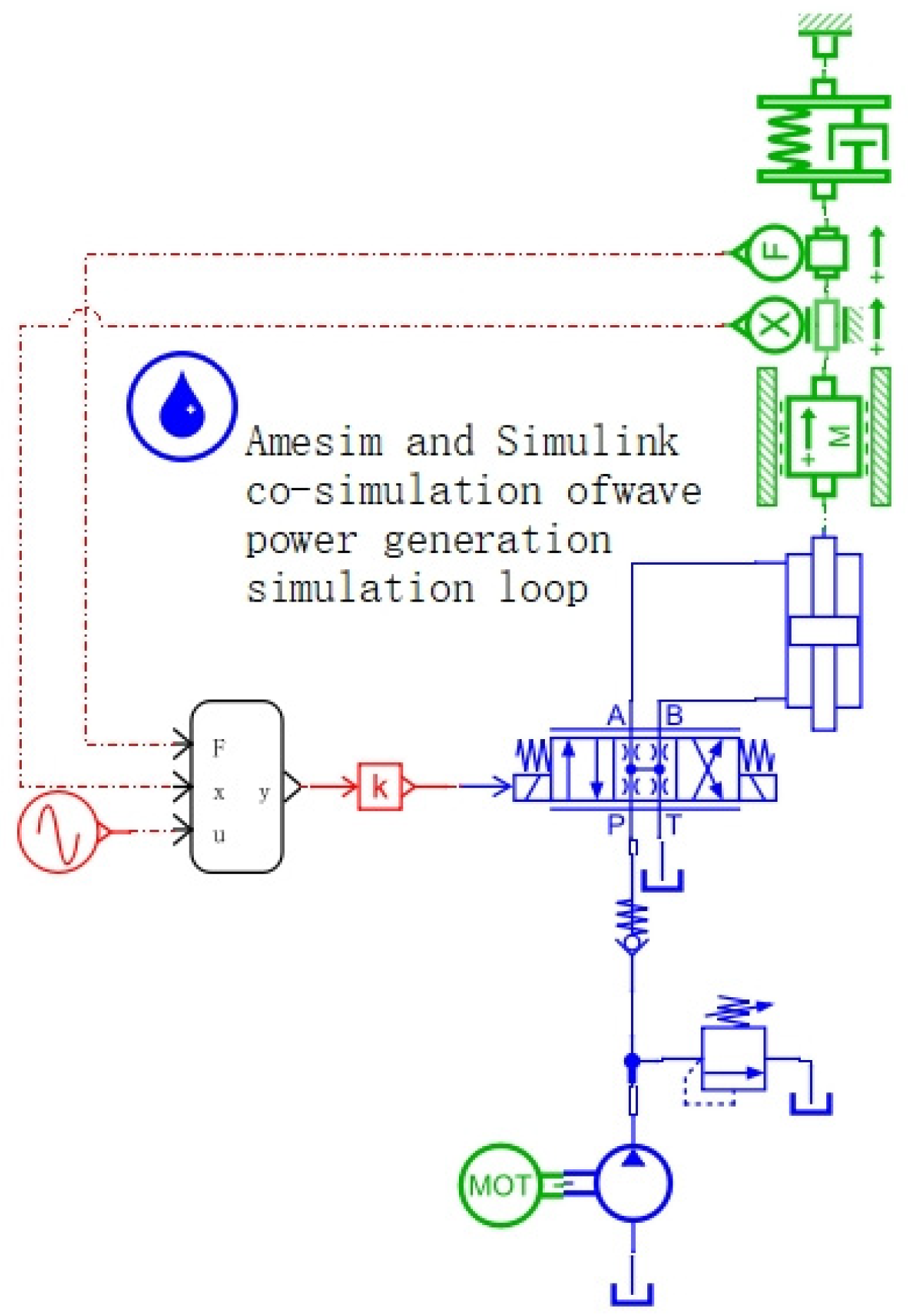
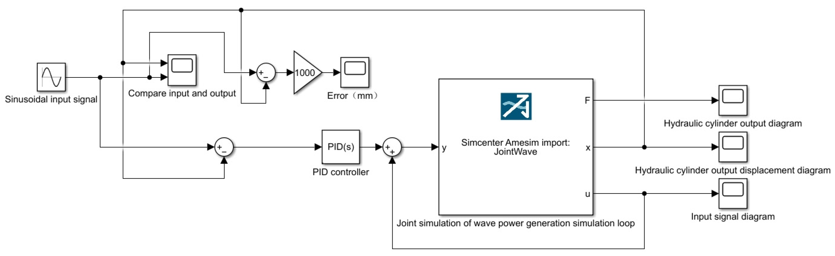
3.2. Establishing an Amesim and Simulink Co-Simulation Model of the Wave Power Generation Simulation Loop

To precisely control the displacement of the hydraulic cylinder to meet its desired specifications, we established a joint simulation model of the wave power generation system using both Amesim and Simulink. Specifically, a proportional–integral–derivative (PID) controller was incorporated within the simulation loop, where blue is proportional control, orange is integral control, and yellow is differential control.as illustrated in Figure 10. Figure 11 shows the co-simulation Amsim model
Once the simulation components, including the input signal, comparison module, error prediction module, PID controller, and output displacement diagram, were created, the Simulink model was constructed, as depicted in Figure 12.
The simulated output displacement of the hydraulic cylinder under PID control is illustrated in Figure 13. Meanwhile, Figure 7 presents the output displacement without PID control. As can be seen from the two figures, under the sinusoidal input signal, the hydraulic cylinder can reach the expected displacement value with or without PID control, but under the control of PID, the movement of the hydraulic cylinder becomes more gentle, which means that the control system can predict and respond to the dynamic changes in the wave more accurately, thus improving the accuracy of power generation efficiency.
Figure 14 compares the input and output signals of the hydraulic cylinder, revealing that the output displacement of the hydraulic cylinder closely resembles its input displacement.
Furthermore, Figure 15 illustrates the error in the output displacement of the hydraulic cylinder, indicating that the maximum error reaches 8 mm for a cylinder travelling distance of 1000 mm. This results in a maximum error rate of 0.8%, thus demonstrating the effectiveness of the PID control strategy, under which the displacement of the hydraulic cylinder closely matches its desired value.

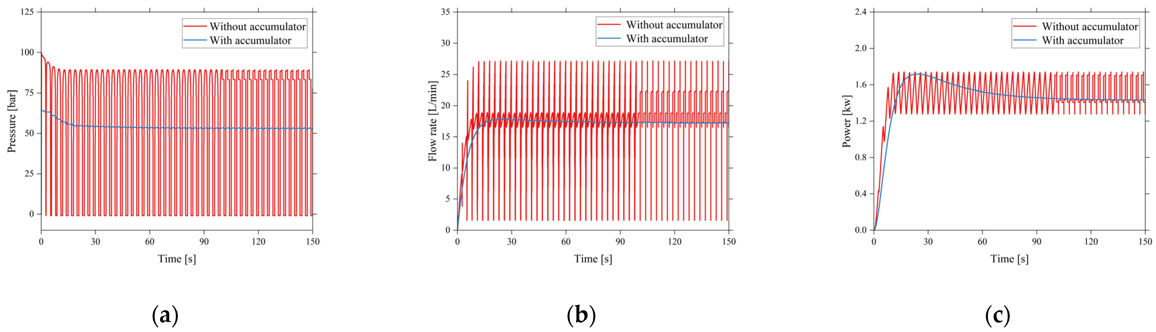
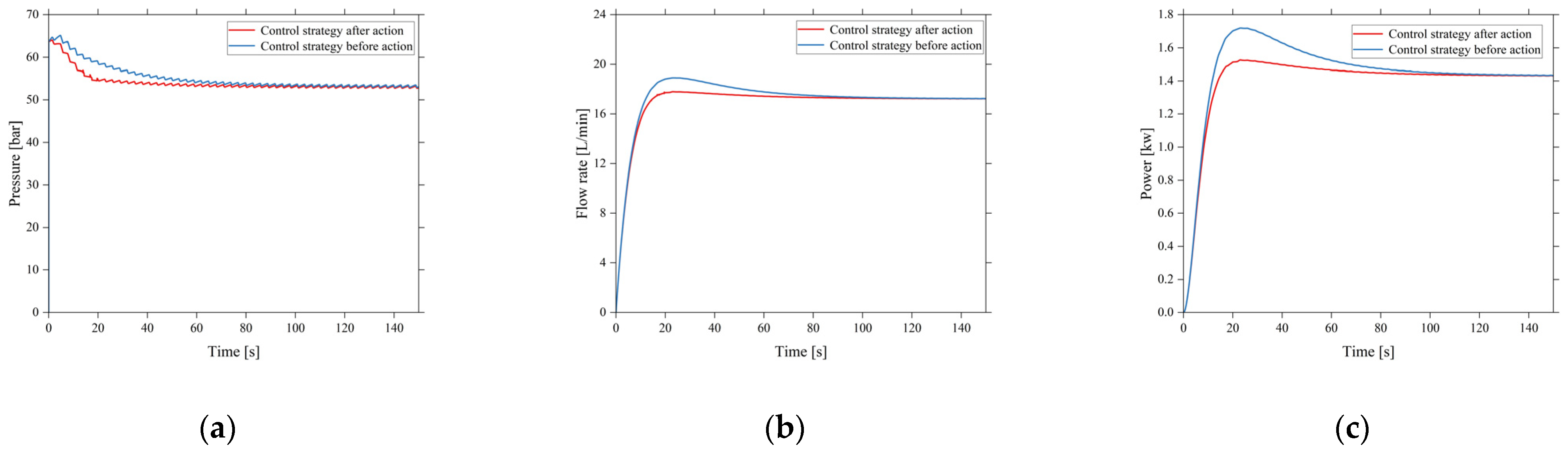
4. Establishing a Simulation Model of the Hydraulic Wave Energy Generation System Using Amesim

Establishing a Simulation Model of the Wave Power Generation System

After introducing PID control into the wave simulation loop, the wave energy generation system was simulated and analyzed using Amesim, as illustrated in Figure 16.
The simulation results reveal that upon incorporating the accumulator, fluctuations in the fluid pressure, flow, and generated power significantly decrease, thus improving energy utilization and the stability of the generated power. Detailed simulation results are depicted in Figure 17.
Notably, power fluctuations resulting from oscillatory wave behaviors represent the primary challenges encountered during wave energy generation. These fluctuations can adversely impact the power grid [25]. To address this issue, hydraulic power generation systems are typically equipped with energy storage and pressure stabilization mechanisms. It can be seen from Figure 17a that after adding the accumulator, the maximum pressure value of the system is close to 6.4 MPa, and the stable value is above 5 MPa. Therefore, this study added the three-position four-way electromagnetic directional valve to the energy storage system and selected these two thresholds to control the three-position four-way electromagnetic directional valve. When the pressure of the oil circuit is higher than 6.4 MPa, the reversing valve is in the right position, and the accumulator absorbs energy. Simulation results incorporating this control strategy are displayed in Figure 18.
The above comparison graphs depicting the inlet pressure and flow of the hydraulic motor before and after implementing the control strategy, as well as those illustrating system power changes (Figure 18), highlight the enhanced stability and reduced power overshoot of the system after incorporating the control strategy. The two thresholds selected also have an important impact on the overall efficiency and stability of the hydraulic power generation system and can be adjusted to adapt to different wave conditions to maximize the energy conversion efficiency and ensure the long-term stable operation of the system.
Furthermore, the capacity of the accumulator was varied to examine its impact on the output power of the system. Notably, simulation results for accumulator capacities of 5 L, 10 L, 15 L, and 20 L are depicted in Figure 19.
The red, blue, yellow, and green curves in Figure 19 represent the variation in the generated power corresponding to accumulator capacities of 5 L, 10 L, 15 L, and 20 L, respectively. Evidently, larger accumulator capacities lead to more stable system outputs.

5. Conclusions

In this study, the energy conversion characteristics of the adaptive storage wave power generation system under the condition of stable random wave were studied by elucidating the energy storage regulation mechanism of the adaptive storage hydraulic system. In particular, the proposed control strategy and the designed wave energy simulation loop in the energy storage system provide important methods and tools for the optimization and verification of the system performance.
Through designing the mathematical model of the hydraulic cylinder displacement control system on Matlab/Simulink platform and introducing PID control strategy, a wave simulation loop that can effectively simulate random wave motion was successfully built. The simulation results verify the feasibility and effectiveness of the control strategy in practical application.
Furthermore, the three-position four-way solenoid directional valve control strategy was introduced into the adaptive energy storage system, which significantly improves the stability of the system and reduces the power overshot. In addition, the simulation analysis on the influence of the accumulator capacity shows that the output power of the system can be more stable with a larger capacity accumulator.
In summary, this study not only explains the key mechanism of hydraulic system in wave energy generation theoretically, but also verified the effectiveness and superiority of the proposed control strategy through experimental simulation, which provides an important reference and guidance for the design and optimization of wave energy power generation systems in the future.

Author Contributions

Conceptualization, J.P. and X.K.; methodology, J.P.; software, M.X.; validation, J.P., X.K. and R.F.; formal analysis, E.Z.; investigation, M.X.; resources, C.H.; data curation, R.F.; writing—original draft preparation, M.X.; writing—review and editing, M.X.; visualization, E.Z.; supervision, J.P.; project administration, J.P. and X.K.; funding acquisition, Z.Z. and J.P. All authors have read and agreed to the published version of the manuscript.

Funding

This research was funded by the Joint Funds of Science Research and Development Program in Henan Province (222103810030 and 222103810039), Key R&D projects in Henan Province (231111222900), and the joint fund (industrial sector) of R&D projects in Henan Province (225101610003).

Data Availability Statement

The data that support the findings of this study are available upon request from the corresponding author, [J.P.].

Acknowledgments

This work was supported by the Renewable Energy Special Fund of the State Oceanic Administration of China, by the National Science Foundation for Young Scientists of Henan University of Science and Technology, and by the Program for Innovative Research Team of Henan University of Science and Technology. Meanwhile, the authors would like to thank Professor Yanjun Liu for his detailed guidance and his collaborators for their great help.

Conflicts of Interest

The authors declare no conflicts of interest.

References

  1. Liu, Y.; Peng, A.; Huang, M. Research progress of PTO system for wave energy converter. Acta Energiae Solaris Sin. 2023, 44, 381–392. [Google Scholar]
  2. Chen, J.; Lan, F.; Guo, H.; Li, J. Review on wave energy power generation control technology. Electr. Power Autom. Equip. 2023, 43, 124–136. [Google Scholar]
  3. Wang, K.; Sheng, S.; Ye, Y.; Zhang, Y.; You, Y. Boost converter converting mechanism and control strategy for hydraulic power generation system in wave energy converter. Autom. Electr. Power Syst. 2017, 41, 173–178. [Google Scholar]
  4. Jusoh, M.A.; Ibrahim, M.Z.; Daud, M.Z.; Albani, A.; Mohd Yusop, Z. Hydraulic power take-off concepts for wave energy conversion system: A review. Energies 2019, 12, 4510. [Google Scholar] [CrossRef]
  5. Ye, Y.; Wang, K.; Zhang, Y.; Huang, Z. Numerical simulation research on energy storage system of wave energy converter. Acta Energiae Solaris Sin. 2020, 41, 30–35. [Google Scholar]
  6. Ma, S.; Wang, X.; Negnevitsky, M.; Franklin, E. Performance investigation of a wave-driven compressed air energy storage system. J. Energy Storage 2023, 73, 109126. [Google Scholar]
  7. Peng, J.; Liu, Y.; Xu, L. Modeling and Simulation Research on Accumulator effect of the Hydraulic Power Take-off System for a Wave Energy converter. In Proceedings of the 2017 5th International Conference on Frontiers of Manufacturing Science and Measuring Technology (FMSMT 2017), Taiyuan, China, 24–25 June 2017; Atlantis Press: Amsterdam, The Netherlands, 2017; pp. 1383–1390. [Google Scholar]
  8. Fan, Z.; Zhang, Y.; Li, X.; Ye, Y. Research status and prospect of hydraulic wave energy power generation technology. Adv. New Energy 2023, 11, 388–394. [Google Scholar]
  9. Liu, C.; Hu, M.; Yang, Q.; Feng, W.; Bao, G.; Zeng, Y. Hardware-in-the-loop simulation technology of wave power generation. J. Mech. Eng. 2021, 57, 286–296. [Google Scholar]
  10. Chen, Q.; Li, Y.; Xu, Z.; Yu, H.; Cai, Y.; Chen, D. Research on hydraulic power take-off system of resonant wave generation device. J. Mech. Eng. 2017, 53, 209–216. [Google Scholar]
  11. Lian, J.; Wang, X.; Wang, X.; Wu, D. Research on Wave Energy Converters. Energies 2024, 17, 1577. [Google Scholar] [CrossRef]
  12. Negri, M.; Malavasi, S. Wave Energy Harnessing in Shallow Water through Oscillating Bodies. Energies 2018, 11, 2730. [Google Scholar] [CrossRef]
  13. Sakr, A.H.; Metwalli, S.M.; Anis, Y.H. Dynamics of Heaving Buoy Wave Energy Converters with a Stiffness Reactive Controller. Energies 2021, 14, 44. [Google Scholar]
  14. Ramezanzadeh, S.; Ozbulut, M.; Yildiz, M. A Numerical Investigation of the Energy Efficiency Enhancement of Oscillating Water Column Wave Energy Converter Systems. Energies 2022, 15, 8276. [Google Scholar] [CrossRef]
  15. Simonetti, I.; Esposito, A.; Cappietti, L. Experimental Proof-of-Concept of a Hybrid Wave Energy Converter Based on Oscillating Water Column and Overtopping Mechanisms. Energies 2022, 15, 8065. [Google Scholar] [CrossRef]
  16. Ye, Y.; Sheng, S.; Le, W.; Wang, K.; Zhang, Y. Simulation study on hydraulic energy conversion system of wave energy device based on MATLAB and Simulink. J. Ocean. Technol. 2021, 40, 87–95. [Google Scholar]
  17. Song, W.; Shi, H.; Liu, P.; Jiang, Q.; Yu, H. Experimental Study on working characteristics of wave energy converter with energy accumulator. Acta Energiae Solaris Sin. 2020, 41, 164–170. [Google Scholar]
  18. Wang, Z.; You, Y.; Sheng, S.; Zhang, Y.; Wang, K.; Ye, Y. Open sea tests of hydraulic autonomous control system in wave energy convertor. Acta Energiae Solaris Sin. 2019, 40, 2085–2090. [Google Scholar]
  19. Chen, Q.; Xu, Z.; Yue, X.; Yu, H.; Chen, D. Characteristicmodeling and parameter optimization of the accumulatorin hydraulic power take-off system for ware powergeneration. J. Basic Sci. Eng. 2019, 27, 226–237. [Google Scholar]
  20. Zhang, Y.; Sheng, S.; You, Y.; Lin, H.; Zhang, C. Design on hydraulic energy storage system of wave energy converters. Mach. Tool Hydraul. 2016, 44, 117–121. [Google Scholar]
  21. Marino, M.; Faraci, C.; Musumeci, R.E. Shoaling waves interacting with an orthogonal current. J. Mar. Sci. Eng. 2020, 8, 281. [Google Scholar] [CrossRef]
  22. Bao, J.; Li, W.; Zhang, D.; Lin, Y.; Liu, H.; Shi, M. Analysis of an inverse pendulum wave power generation system with pressure-maintaining storage based on hydraulic transmission. Autom. Electr. Power Syst. 2012, 36, 205–209. [Google Scholar]
  23. Zhang, W.; Liu, Y.; Li, D. Simulation research on the hydraulic servo control type wave power station. Acta Energiae Solaris Sin. 2016, 3, 570–576. [Google Scholar]
  24. Song, W.; Shi, H.; Liu, P. Simulation study of oscillating buoy wave energy generation system based on double-stroke hydraulic transmission. Acta Energiae Solaris Sin. 2016, 37, 256–260. [Google Scholar]
  25. Moreno-Torres, P.; Blanco, M.; Navarro, G.; Lafoz, M. Power smoothing system for wave energy converters by means of a supercapacitor-based energy storage system. In Proceedings of the 2015 17th European Conference on Power Electronics and Applications (EPE’15 ECCE-Europe), Geneva, Switzerland, 8–10 September 2015; IEEE: Piscataway, NJ, USA, 2015; pp. 1–9. [Google Scholar]
Figure 1. Schematic of a storage-type hydraulic wave power generation system. 1. Frequency conversion motor; 2. hydraulic pump; 3. relief valve; 4. check valve; 5. three-position four-way servo valve; 6. double-acting rod hydraulic cylinder 1; 7. double-acting rod hydraulic cylinder 2; 8. rectifier valve group; 9. three-position four-way directional control valve; 10. accumulator 1; 11. proportional flow control valve; 12. variable hydraulic motor; 13. permanent magnet synchronous generator; 14. accumulator 2.
Energies 17 04151 g001
Figure 2. Schematic of control signals within the wave simulation loop.
Energies 17 04151 g002
Figure 3. Overall block diagram of the hydraulic cylinder control system.
Energies 17 04151 g003
Figure 4. Creation of the transfer function model using Simulink.
Energies 17 04151 g004
Figure 5. System step response.
Energies 17 04151 g005
Figure 6. System sinusoidal response.
Energies 17 04151 g006
Figure 7. Displacement diagram without PID control.
Energies 17 04151 g007
Figure 8. System stability simulation model.
Energies 17 04151 g008
Figure 9. Comparison of stability simulation with or without PID control system.
Energies 17 04151 g009
Figure 10. Structural diagram of the PID controller.
Energies 17 04151 g010
Figure 11. Co-simulation model of Amesim.
Energies 17 04151 g011
Figure 12. Co-simulation model of Simulink.
Energies 17 04151 g012
Figure 13. Displacement diagram with PID control.
Energies 17 04151 g013
Figure 14. Hydraulic cylinder input vs. the output signal (m).
Energies 17 04151 g014
Figure 15. Error in the output displacement of the hydraulic cylinder (mm).
Energies 17 04151 g015
Figure 16. Simulation model of the wave energy generation system.
Energies 17 04151 g016
Figure 17. Comparison between the simulation results of the pressure circuit with or without the accumulator: (a) pressure comparison; (b) velocity comparison; (c) power comparison.
Energies 17 04151 g017
Figure 18. Comparison between the simulation results obtained before and after incorporating the control strategy: (a) pressure comparison; (b) velocity comparison; (c) power comparison.
Energies 17 04151 g018
Figure 19. Comparison between the simulation results obtained at varying capacities of the accumulator.
Energies 17 04151 g019
Disclaimer/Publisher’s Note: The statements, opinions and data contained in all publications are solely those of the individual author(s) and contributor(s) and not of MDPI and/or the editor(s). MDPI and/or the editor(s) disclaim responsibility for any injury to people or property resulting from any ideas, methods, instructions or products referred to in the content.

