

Study on Flow Heat Transfer and Particle Deposition Characteristics in a Kettle Reboiler
Abstract
1. Introduction
2. Methods
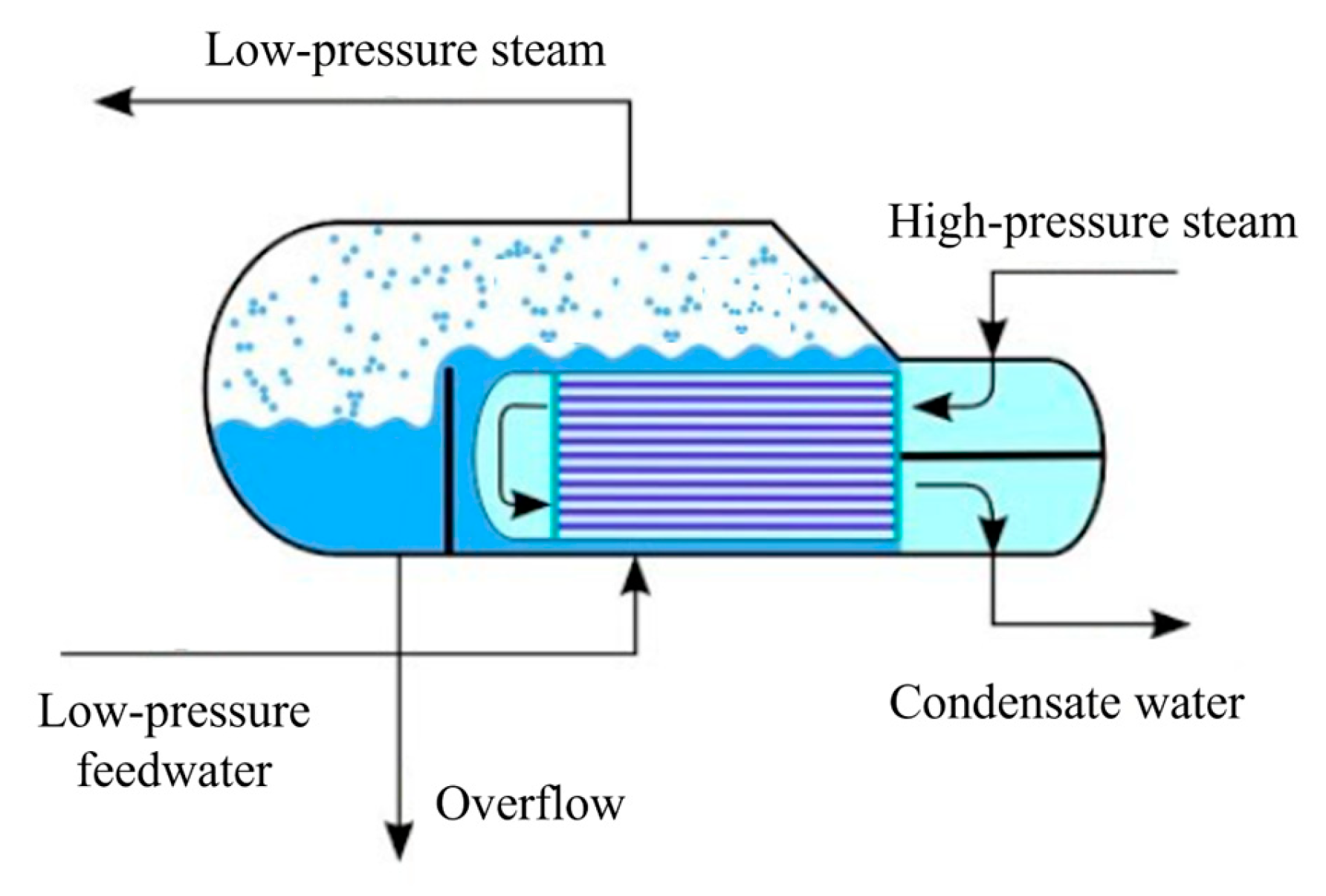
2.1. Physical Model
2.2. Numerical Calculation Model
3. Results
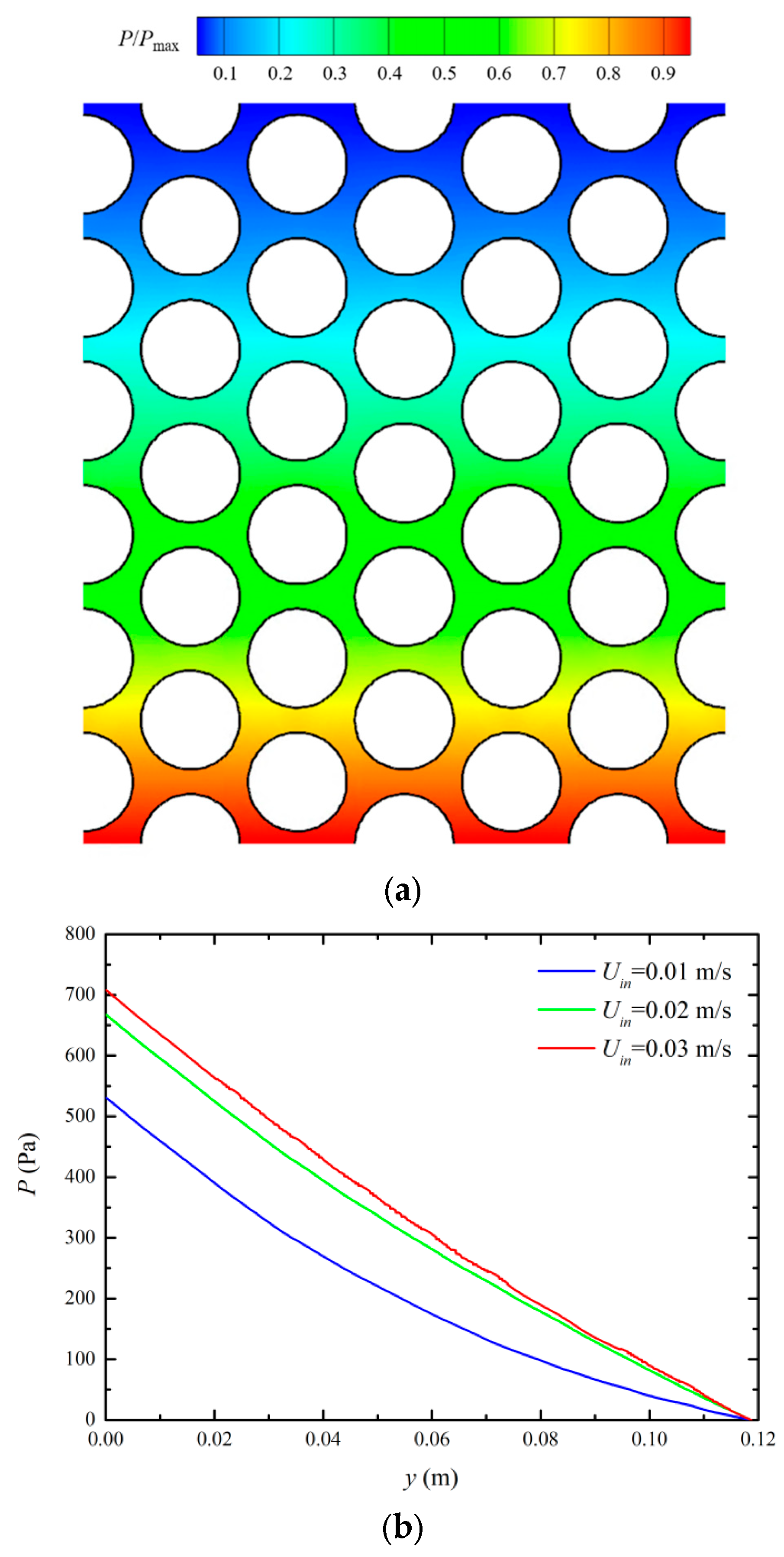
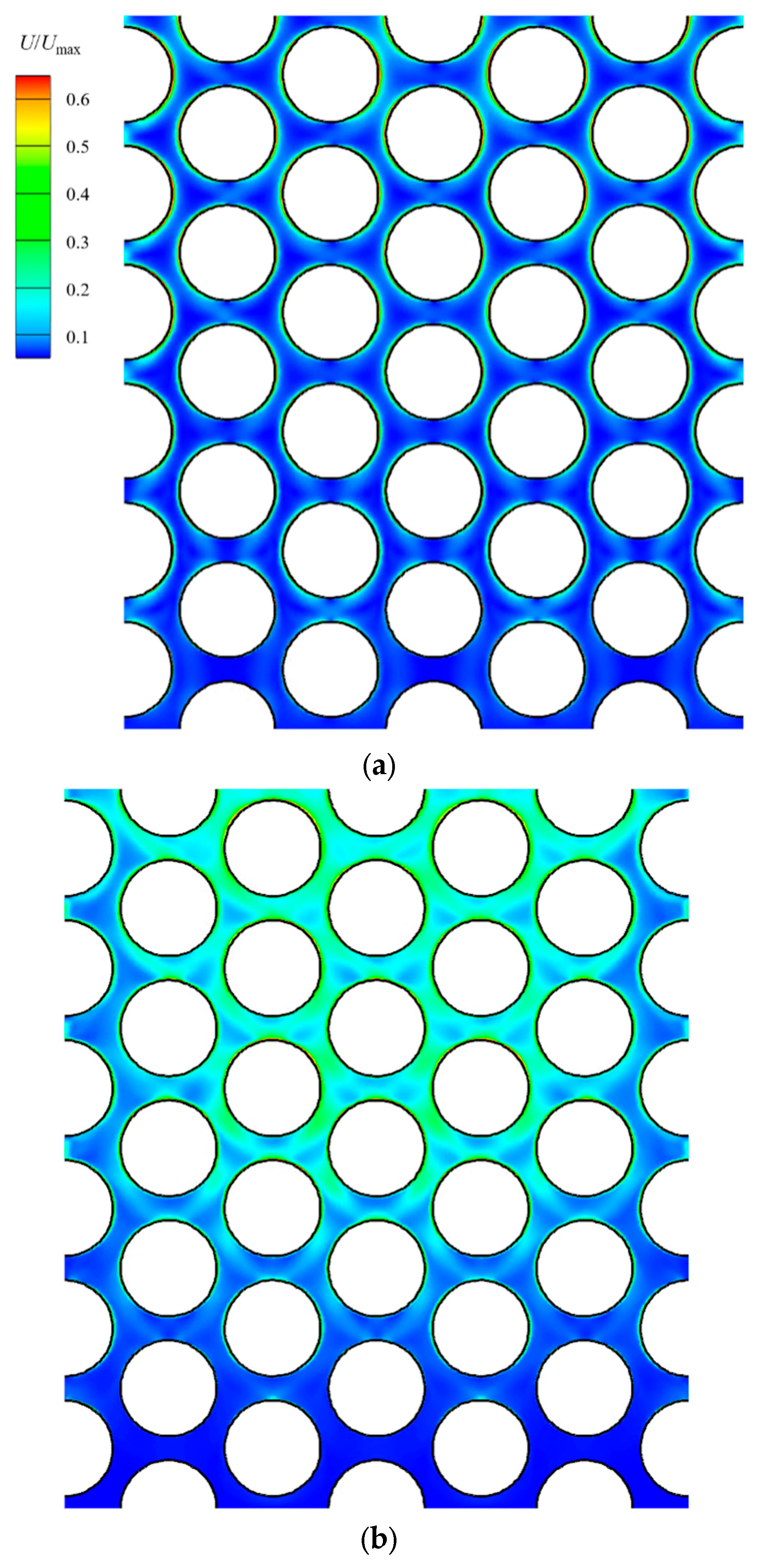
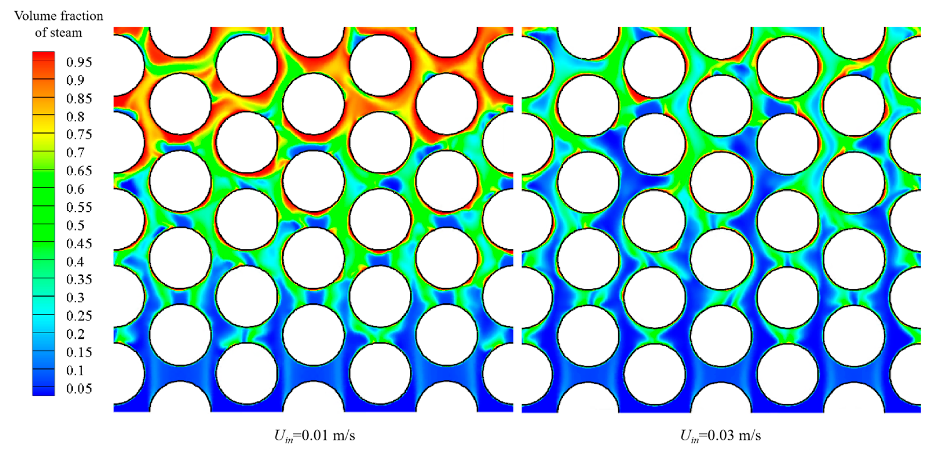
3.1. Flow and Heat Transfer
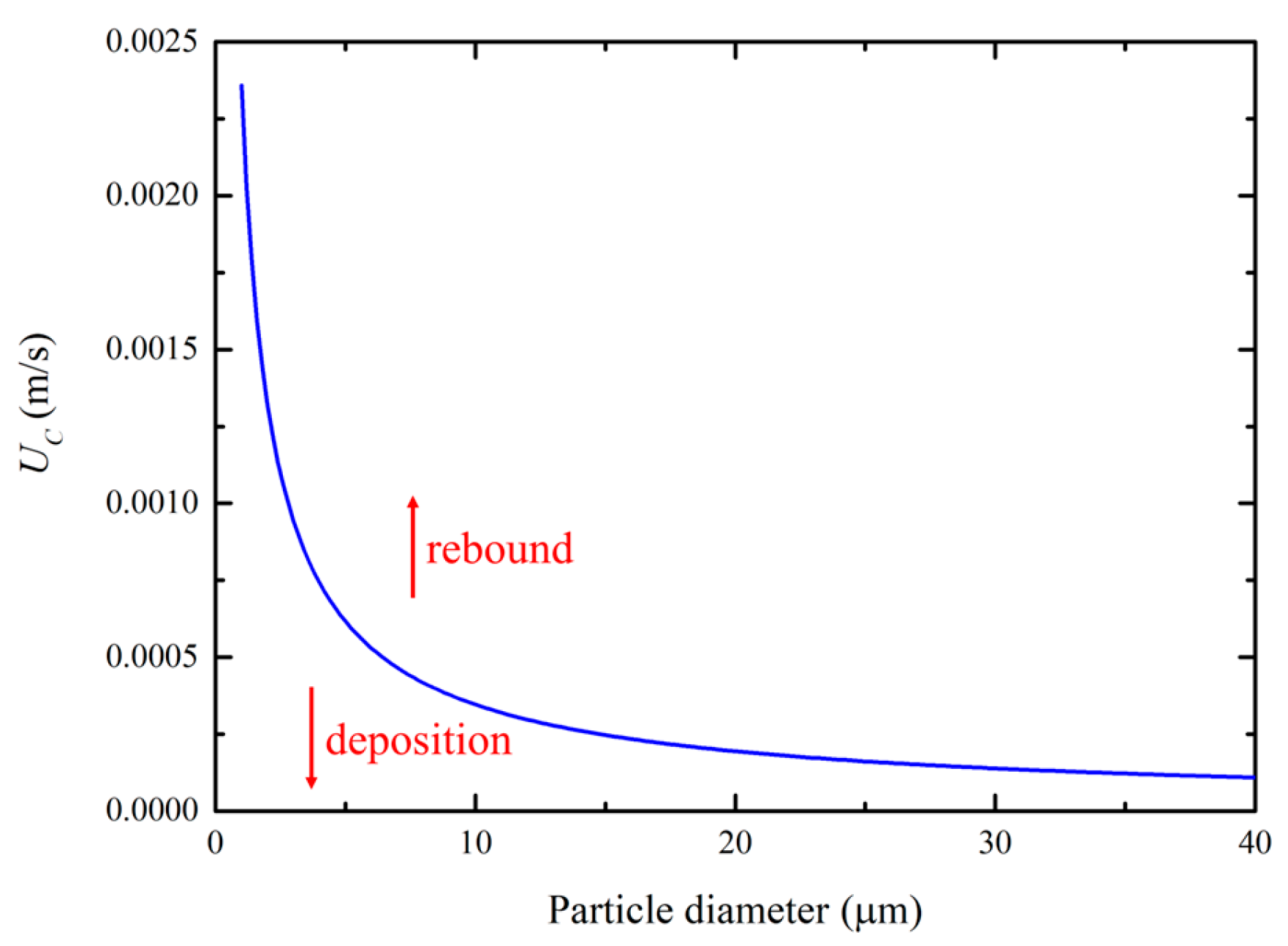
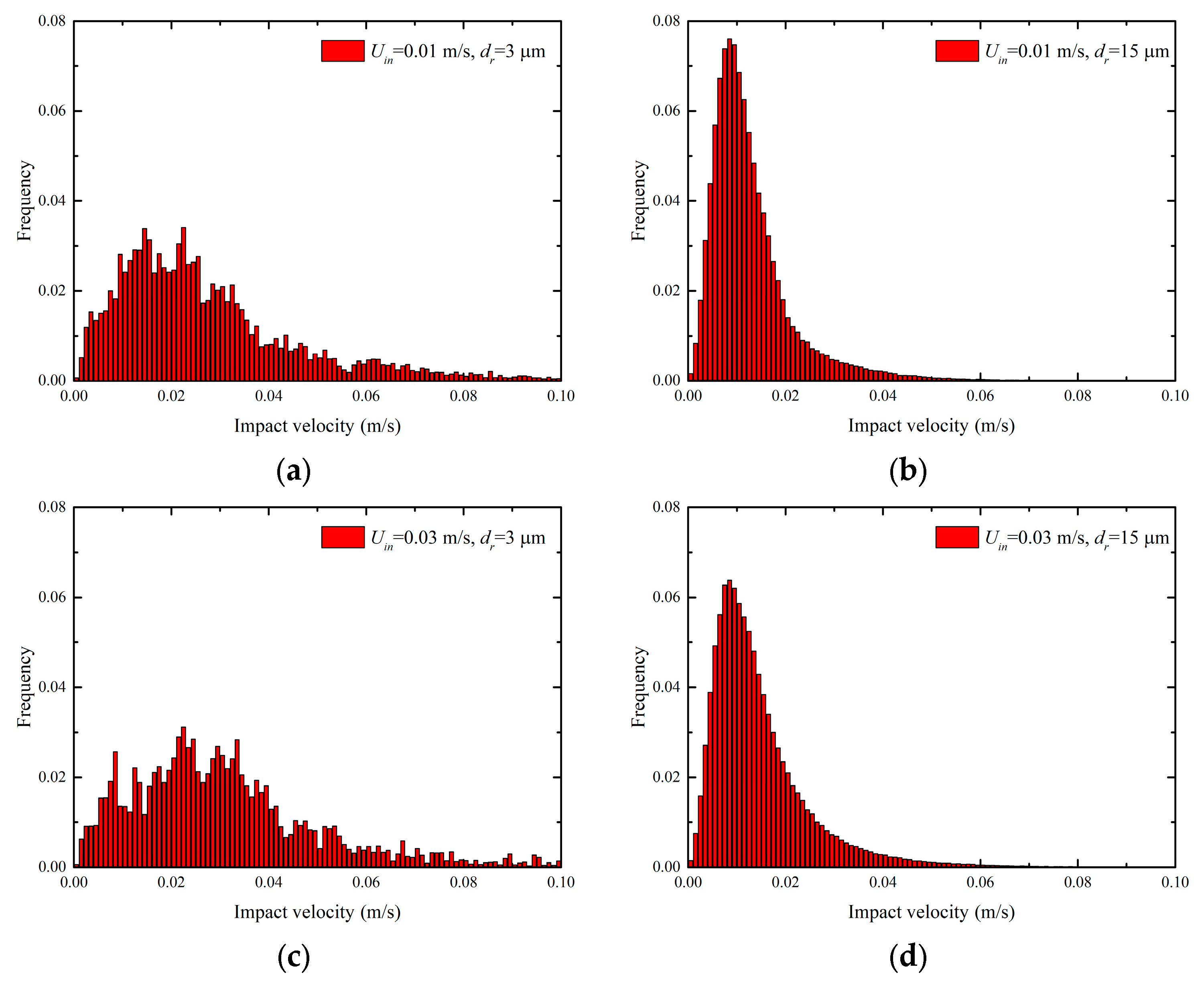
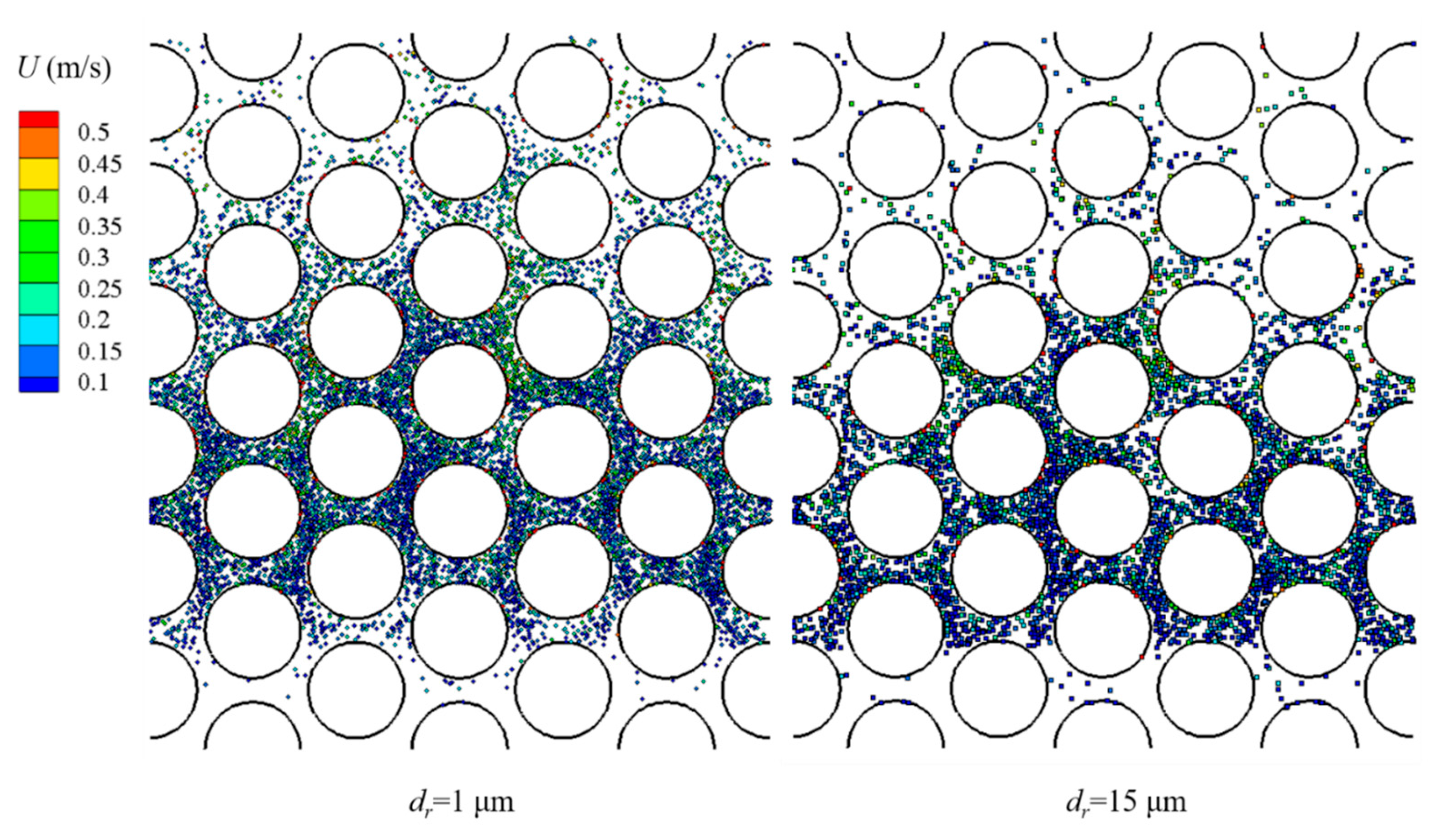
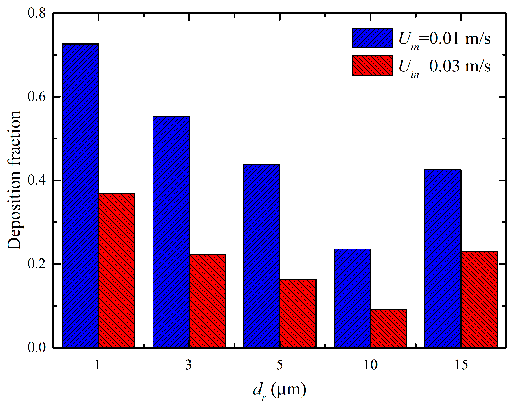
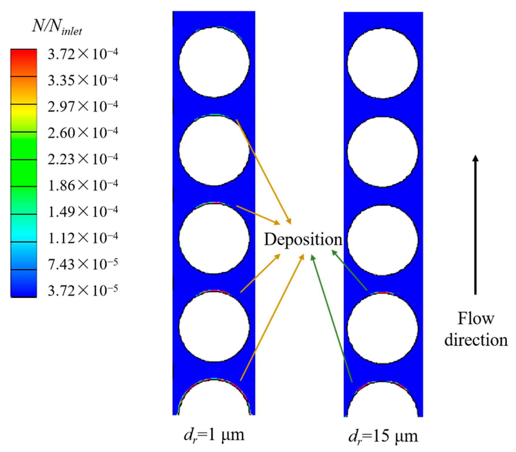
3.2. Particle Deposition
4. Conclusions
Author Contributions
Funding
Data Availability Statement
Conflicts of Interest
Nomenclature
| CD | particle drag coefficient |
| CR | correction factor |
| dr | particle diameter (m) |
| E | Young’s modulus (Pa) |
| F | body force (N/m3) |
| h | specific enthalpy (J/kg) |
| g | gravitational acceleration vector (m/s2) |
| P | fluid pressure (Pa) |
| q | heat flux (J/m2) |
| R | surface tension (N/m2) |
| t | time (s) |
| U | fluid velocity vector (m/s) |
| v | Poisson’s ratio |
| Greek letters | |
| α | volume fraction |
| ρ | density (kg/m3) |
| τr | particle relaxation time |
| μ | viscosity (Pa·s) |
| ωA | combined surface energy (J/m2) |
References
- Kumar, A.; Jha, H.S. Study, Design and Simulation of Kettle Type Reboiler. Ph.D. Thesis, College of Engineering, UPES, Dehradun, India, 2010. [Google Scholar]
- Kumar, A.; Hung, K.; Wang, C. Nucleate pool boiling heat transfer from high-flux tube with dielectric fluid HFE-7200. Energies 2020, 13, 2313. [Google Scholar] [CrossRef]
- Li, S.; Li, P.; Zhang, X. Development and Application of High-Flux Heat Exchangers. Chem. Eng. Manag. 2021, 58–59. [Google Scholar] [CrossRef]
- Mehralizadeh, A.; Shabanian, S.R.; Bakeri, G. Effect of modified surfaces on bubble dynamics and pool boiling heat transfer enhancement: A review. Therm. Sci. Eng. Prog. 2020, 15, 100451. [Google Scholar] [CrossRef]
- Maslovaric, B.; Stevanovic, V.D.; Milivojevic, S. Numerical simulation of two-dimensional kettle reboiler shell side thermal—Hydraulics with swell level and liquid mass inventory prediction. Int. J. Heat Mass Transf. 2014, 75, 109–121. [Google Scholar] [CrossRef]
- McNeil, D.A.; Bamardouf, K.; Burnside, B.M.; Almeshaal, M. Investigation of flow phenomena in a kettle reboiler. Int. J. Heat Mass Transf. 2010, 53, 836–848. [Google Scholar] [CrossRef]
- Zhang, H.F.; Ahmadi, G. Aerosol particle transport and deposition in vertical and horizontal turbulent duct flows. J. Fluid Mech. 2000, 406, 55–80. [Google Scholar] [CrossRef]
- Beghein, C.; Jiang, Y.; Chen, Q.Y. Using large eddy simulation to study particle motions in a room. Indoor Air 2005, 15, 281–290. [Google Scholar] [CrossRef]
- Morsi, Y.S.; Tu, J.Y.; Yeoh, G.H.; Wang, W. Principal characteristics of turbulent gas-particulate ow in the vicinity of single tube and tube bundle structure. Chem. Eng. Sci. 2004, 59, 3141–3157. [Google Scholar] [CrossRef]
- Fu, S.; Cao, G.; Chen, Q.; Sun, X.; Ou, G.; Zhou, F.; Li, L. Analysis of fly ash deposition blockage mechanism and structure optimization of low temperature economizer. Chem. Ind. Eng. Prog. 2022, 41, 4035–4046. [Google Scholar]
- Han, Z.; Lu, H.; Zhao, W.; Wang, Z.; Xiao, Z. Numerical simulation study of particle deposition and heat transfer characteristics in heat transfer pipes with dimpled dimple surface. Energy Environ. Prot. 2023, 37, 201–208. [Google Scholar]
- Zhuang, Z.; Wang, G.; Xu, J.; Zhang, C.; Zhang, C. Study on deposition characteristics of particulate fouling in U-shaped sewage heat exchange tubes. Heat. Vent. Air Cond. 2023, 53, 166–172. [Google Scholar]
- Xu, Z.; Li, J.; Han, Z.; Yang, X. Investigation of deposition characteristics on tube-bundle heat exchanger with an improved ash particle model. Powder Technol. 2023, 413, 118027. [Google Scholar] [CrossRef]
- Zhang, Z.; Tian, H.; Ding, Z.; Zhang, Y.; Wang, Z. Influence and Optimization of Soot Particles Deposition on Tube Heat Exchanger Performance. J. Eng. Thermophys. 2023, 44, 769–780. [Google Scholar]
- Liu, K.; Wei, B.; Zhang, Y.; Wang, J.; Chen, L.; Liu, N. Numerical simulation of particle deposition on wall surfaces of heat exchange tube bundles. Coal Convers. 2023, 46, 95–102. [Google Scholar]
- Li, M. Numerical Study of Impurity Distribution in Two-Phase Flow on the Secondary Side of Steam Generator. Master’s Thesis, Harbin Engineering University, Harbin, China, 2023. [Google Scholar]
- Zou, J.; Jiang, J.; Li, Q.; Yang, X.; Chu, H.; Di, X.; Zhou, J. Study on Heat Transfer Characteristics and Ash Wear of Elliptical Finned Tubes. Boil. Technol. 2024, 55, 7–14. [Google Scholar]
- Akbari, V.; Borhani, T.; Nejad, G.; Shamiri, A.; Shafeeyan, M. Computational fluid dynamics modeling of gas-solid fluidized bed reactor: Influence of numerical and operating parameters. Exp. Comput. Multiph. Flow 2024, 6, 85–125. [Google Scholar] [CrossRef]
- Sun, Q.; Liu, B.; Wang, X.; Peng, W.; Shi, L. Fluid-structure coupling for particle deposition-resuspension predictions in tube bundle heat exchangers based on dynamic mesh method. Chem. Eng. Sci. 2024, 297, 120313. [Google Scholar] [CrossRef]
- Lu, H.; Wang, Y.; Li, H.; Zhao, W. Numerical Simulation of Turbulent Structure and Particle Deposition in a Three-Dimensional Heat Transfer Pipe with Corrugation. Energies 2024, 17, 321. [Google Scholar] [CrossRef]
- McNeil, D.A.; Burnside, B.M.; Miller, K.M.; Tarrad, A.H. A comparison between HIGHFLUX and plain tubes, boiling pentane in a horizontal kettle reboiler. Appl. Therm. Eng. 2002, 22, 803–814. [Google Scholar] [CrossRef]
- ANSYS Inc. Ansys Fluent Theory Guide; ANSYS Inc.: Canonsburg, PA, USA, 2021. [Google Scholar]
- Oliani, S.; Casari, N.; Pinelli, M.; Carnevale, M. Simulation of Particle Trajectories in Gas Turbine Components and Assessment of Unsteady Effects Using an Efficient Eulerian-Lagrangian Technique. Energies 2023, 16, 2810. [Google Scholar] [CrossRef]
- Kurul, N.; Podowski, M.Z. On the modeling of multidimensional effects in boiling channels. In Proceedings of the 27th National Heat Transfer Conference, Minneapolis, MN, USA, 28–31 July 1991. [Google Scholar]
- Menter, F.R. Two-Equation Eddy-Viscosity Turbulence Models for Engineering Applications. AIAA J. 1994, 32, 1598–1605. [Google Scholar] [CrossRef]
- Gao, N.; Niu, J.; He, Q.; Zhu, T.; Wu, J. Using RANS turbulence models and Lagrangian approach to predict particle deposition in turbulent channel flows. Build. Environ. 2012, 48, 206–214. [Google Scholar] [CrossRef]
- Sun, Q.; Wang, X.; Shi, L.; Peng, W. Aerodynamic Drag of Rod-shaped Particles Near-wall in Nuclear Reactor. At. Energy Sci. Technol. 2023, 57, 2067–2076. [Google Scholar]
- Liu, P.; Liu, W.; Gong, K.; Han, C.; Zhang, H.; Sui, Z.; Hu, R. Numerical study on particulate fouling characteristics of flue with a particulate fouling model considering deposition and removal mechanisms. Energies 2022, 15, 8708. [Google Scholar] [CrossRef]
- Kim, O.V.; Dun, P.F. A microsphere-surface impact model for implementation in computational fluid dynamics. J. Aerosol Sci. 2007, 38, 532–549. [Google Scholar] [CrossRef]
- Sun, Q.; Chen, T.; Peng, W.; Wang, J.; Yu, S. A numerical study of particle deposition in HTGR steam generators. Nucl. Eng. Des. 2018, 332, 70–78. [Google Scholar] [CrossRef]


| Type | Parameter | Value |
|---|---|---|
| Working conditions | Inlet velocity (m/s) | 0.01–0.03 |
| Inlet temperature (K) | 540 | |
| Particle diameter (μm) | 1~15 | |
| Pressure (MPa) | 5.5 | |
| Wall temperature (K) | 550.15 | |
| Fluid | Density (kg/m3) | 767.87 (liquid phase)/28.06 (gas phase) |
| Dynamic viscosity (Pa·s) | 9.75 × 10⁻⁵ (liquid phase)/1.83 × 10−5 (gas phase) | |
| Thermal conductivity (W/m/K) | 0.596 (liquid phase)/0.057 (gas phase) | |
| Surface tension (N/m) | 0.021 | |
| Boiling point (K) | 543.12 | |
| Particles/ wall | Density (kg/m3) | 7970 |
| Young’s modulus (GPa) | 190 | |
| Poisson’s ratio | 0.27 | |
| Surface energy (J/m2) | 2.56 |
Disclaimer/Publisher’s Note: The statements, opinions and data contained in all publications are solely those of the individual author(s) and contributor(s) and not of MDPI and/or the editor(s). MDPI and/or the editor(s) disclaim responsibility for any injury to people or property resulting from any ideas, methods, instructions or products referred to in the content. |
© 2024 by the authors. Licensee MDPI, Basel, Switzerland. This article is an open access article distributed under the terms and conditions of the Creative Commons Attribution (CC BY) license (https://creativecommons.org/licenses/by/4.0/).
Share and Cite
Liu, X.; Sun, Q.; Tang, H.; Peng, W.; Zhang, M.; Zhao, G.; Fu, T. Study on Flow Heat Transfer and Particle Deposition Characteristics in a Kettle Reboiler. Energies 2024, 17, 4183. https://doi.org/10.3390/en17164183
Liu X, Sun Q, Tang H, Peng W, Zhang M, Zhao G, Fu T. Study on Flow Heat Transfer and Particle Deposition Characteristics in a Kettle Reboiler. Energies. 2024; 17(16):4183. https://doi.org/10.3390/en17164183
Chicago/Turabian StyleLiu, Xue, Qi Sun, Hui Tang, Wei Peng, Mingbao Zhang, Gang Zhao, and Tairan Fu. 2024. "Study on Flow Heat Transfer and Particle Deposition Characteristics in a Kettle Reboiler" Energies 17, no. 16: 4183. https://doi.org/10.3390/en17164183
APA StyleLiu, X., Sun, Q., Tang, H., Peng, W., Zhang, M., Zhao, G., & Fu, T. (2024). Study on Flow Heat Transfer and Particle Deposition Characteristics in a Kettle Reboiler. Energies, 17(16), 4183. https://doi.org/10.3390/en17164183