Article

Study on Flow Heat Transfer and Particle Deposition Characteristics in a Kettle Reboiler

1
State Key Laboratory of Low-carbon Thermal Power Generation Technology and Equipments, Harbin Boiler Company Limited, Harbin 150046, China
2
Institute of Nuclear Energy and New Energy Technology, Tsinghua University, Beijing 100084, China
3
Department of Energy and Power Engineering, Tsinghua University, Beijing 100084, China
*
Authors to whom correspondence should be addressed.
Energies 2024, 17(16), 4183; https://doi.org/10.3390/en17164183
Submission received: 18 July 2024 / Revised: 9 August 2024 / Accepted: 20 August 2024 / Published: 22 August 2024
(This article belongs to the Special Issue Heat Transfer and Multiphase Flow)

Abstract

:
A kettle reboiler uses the latent heat from the condensation of high-temperature and high-pressure steam in the tube to produce low-pressure saturated steam in the outer shell. The deposition of particles on the tube may change the boiling heat transfer mode from nucleate boiling to natural convection, thereby deteriorating the heat transfer performance of the kettle reboiler. Therefore, it is very important to explore the deposition characteristics of particles in the kettle reboiler. In this study, the RPI boiling model based on the Euler–Euler method is used to analyze the water boiling process on the surface of the tube bundle. The DRW model and critical adhesion velocity model based on the Euler–Lagrangian method are used to calculate the motion of particles during the boiling process and the deposition (rebound) behavior. The results show that the boiling of liquid water enhances the local flow velocity of the fluid, so that the maximum flow velocity appears around the near-wall region. The local high-speed flow disperses the particles in the wake flow of the tube bundle, which inhibits the impact of particles on the wall. As the particle size increases, the wall adhesion and fluid drag on the particles are weakened, and the gravity effect gradually becomes dominant, increasing the residence time of the particles in the tube bundle and the frequency of particle impact on the wall. The particle deposition ratio first decreases and then increases. Ultimately, most particles will be deposited in the low-speed area at the end of the tube bundle.

1. Introduction

A kettle-type reboiler can utilize the latent heat released by steam condensation in the high-pressure side loop as the heat source for the boiling of liquid water on the low-pressure side, achieving heat recovery and utilization [1]. It has numerous applications in the fields of petrochemicals, industrial engineering, and nuclear steam supply. However, in practical applications, due to the limited pressure difference between the high-pressure side and the low-pressure side, the corresponding temperature difference between the high-temperature primary side and the low-temperature secondary side is often very limited in terms of economy. Under certain operating conditions, this can easily cause the heat transfer to deviate from the nucleate boiling regime, thereby reducing the heat transfer efficiency. To enhance the nucleate boiling capacity of the tube bundle under limited wall superheat conditions, a porous medium structure can be sintered onto the heat exchange tube surface using powder metallurgy—namely, sintered high-flux tubes [2]. The porous structure on the surface of the high-flux tubes increases the number of bubble cavities on the tube wall and the heat exchange area, thereby comprehensively improving the heat transfer capacity of the tubes [3]. However, with the prolonged operation of the kettle-type reboiler, impurity particles in the loop and sintered powder on the high-flux tubes may detach and enter the shell due to fluid scouring or vibration. These particles can be deposited on the surface of the tube bundle in the kettle-type reboiler, reducing its heat transfer performance [4]. Compared with particle deposition in single-phase fluids, the continuous phase-change boiling on the tube bundle surface in the kettle-type reboiler alters the near-wall flow field characteristics, thus affecting the particle deposition characteristics [5,6]. Therefore, it is of significance to investigate the deposition behavior of the particles on the tube bundle surface under boiling conditions in the kettle-type reboiler.
In terms of studying particle motion and deposition behavior, numerical simulation is an important method in investigating particle deposition characteristics under different factors. Among the simulation methods, particle deposition simulation based on the Euler–Lagrange approach is the primary technique. Zhang et al. [7] accurately simulated the turbulent deposition and diffusion of particles in simple geometries using direct numerical simulation (DNS) and the discrete random walk (DRW) model. Beghein et al. [8] combined large eddy simulation (LES) and the DRW model to study particle transport behavior in square channels. However, DNS and LES involve significant computational effort for complex geometries in engineering problems. For the complex structures of heat exchanger tube bundles, the Reynolds-averaged Navier–Stokes (RANS) equations are commonly used in particle deposition studies. Morsi [9] used the RANS equations to study the effects of the particle flow and deposition characteristics in a single pipe and in tube bundles (multiple pipes arranged in parallel), exploring the deposition and corrosion behavior of the particles on the wall under the influence of turbulent pulsation, the particle size, and the rebound probability. Fu et al. [10] adopted the shear stress transport (SST k-ω) model and the discrete phase model (DPM) to study the behavior of fly ash deposition and blockage in economizer gaps, optimized the fin arrangement structure, and conducted a flow field analysis. Han et al. [11] investigated the particle deposition characteristics in dimpled pipes using the Reynolds stress model (RSM) and the DRW model. Zhuang Zhaoyi et al. [12] studied particle fouling deposition on the heat exchange wall under different sewage flow rates, as well as the sewage viscosity, particle concentrations, and particle sizes, in U-shaped sewage heat exchange pipes. Xu et al. [13] proposed a stochastic function model combined with dynamic mesh technology to simulate the change in particle deposition behavior on the tube bundle surface, considering the impact of different flow rates and particle sizes. Zhang et al. [14] considered the removal mechanism of deposited particles and studied the effect of the heat exchange tube shape and arrangement on the distribution of particle deposition in the tube-type heat exchanger. Liu et al. [15] considered the influence of the atmosphere on the particle stickiness and the impact of impurity particles on the deposition probability, studying the effects of different models, the longitudinal pitch, and the wall temperature on particle deposition in heat exchanger tube bundles. Li et al. [16] used the RNS k-ε turbulence model and the DPM model to study the impact of the thermohydraulic parameters of steam generators on impurity particle migration, secondary side flow heat transfer, and ion distribution. Zou et al. [17] combined particle motion equations and erosion models to simulate the erosion wear of particles on elliptical finned tubes. Akbari et al. [18] coupled computational fluid dynamics and population balance equations to study the parameters affecting the performance of fluidized bed reactors. Sun et al. [19] combined dynamic mesh technology, particle deposition rebound models, and resuspension detachment models to simulate the flow–solid coupling and thermal resistance development under long-term particle deposition in heat exchanger tube bundles, analyzing the balance laws of particle deposition and detachment. Lu et al. [20] employed the Reynolds stress model (RSM) and the DPM to simulate particle deposition in a 3D corrugated rough-walled channel. The effects of the turbulent structure on particle motion were discussed.
In summary, existing studies mainly focus on particle deposition in single-phase fluids, with fewer studies on the particle deposition behavior on the tube bundle surface under boiling conditions. This paper studies the pool boiling around the tubes of the kettle-type reboiler using a boiling phase-change model based on a Euler–Euler multiphase flow. Then, a discrete particle random walk model based on Euler–Lagrange is used to calculate the particle motion and deposition behavior. This work explores the influence of different factors on the particle deposition behavior, providing a theoretical foundation for the operation and fouling analysis of kettle-type reboilers.

2. Methods

2.1. Physical Model

Figure 1 shows the structural schematic and workflow of a kettle reboiler [21]. High-temperature, high-pressure steam flows through the U-shaped tube bundle into the kettle reboiler, transferring heat to the low-temperature, low-pressure liquid water outside the tubes. The liquid water inside the shell absorbs heat and boils. Then, boiling steam exits through the top outlet of the kettle reboiler, completing the steam generation process.
In engineering processes, there are usually thousands of tubes in a kettle reboiler, which renders the complete simulation of its internal flow and heat transfer processes computationally intensive. To facilitate the calculations, this study simplifies the actual U-shaped tube bundle of the kettle reboiler and focuses on the boiling of water and the deposition of particles carried by the fluid in the local tube bundle cross-section shown in Figure 2. The simplification assumes that the tube length is infinitely long, with no influence from the kettle reboiler shell. Thus, the flow and heat transfer in the axial direction of the tube are similar, and the 2D cross-section of the kettle reboiler is representative. The inlet boundary assumes that liquid water enters the tube bundle region from bottom to top at a constant flow rate and exits at a pressure outlet boundary. Due to the continuous condensation of steam inside the tube bundle, it assumes a constant wall temperature boundary around the tube bundles. The boundaries on both sides of the computational domain are symmetric boundaries. The single tube diameter in the tube bundle is 19 mm, with a tube spacing-to-diameter ratio of 1.25, and the tube bundle is arranged in an equilateral triangular layout.
The working conditions and main physical parameters involved in this study are shown in Table 1. The operation condition refers to a steam production application in a nuclear power plant. It is assumed that the particles and the tube walls are composed of the same stainless steel material.

2.2. Numerical Calculation Model

The flow and heat transfer calculations inside the kettle reboiler need to consider the phase-change boiling process of liquid water and the motion and deposition of particles in the shell. This study uses the Euler–Euler–Lagrange method to simulate the above processes by commercial code ANSYS FLUENT 2021 [22]. Specifically, the Euler–Euler method calculates the boiling phase change of liquid water, and the Euler–Lagrange method calculates the interaction between gas–liquid mixed water and particles [23]. The control equations involved in the Euler–Euler method are as follows.
The continuity equation for phase q is expressed as
t α q ρ q + α q ρ q U q = m p q m q p
where subscripts p and q represent the liquid and vapor phases of water, respectively; α is the volume fraction; ρ is the fluid density (kg/m3); U is the fluid velocity vector (m/s); and m is the mass source term due to the phase change (kg/m3/s). The mass conversion from the liquid phase to the vapor phase is calculated using the Rensselaer Polytechnic Institute (RPI) boiling model assuming subcooled boiling [24].
In the Euler–Euler method, the velocities of each phase are calculated independently. The momentum equation for phase q is
t α q ρ q U q + α q ρ q U q U q = α q P + τ ¯ ¯ q + α q ρ q g + R p q + F q
where P is the fluid pressure (Pa), g is the gravitational acceleration vector (m/s2), Rpq includes the surface tension between the vapor and liquid phases and the momentum source terms generated by the phase change (N/m2), τ ̿ q is the stress–strain tensor of phase q (Pa), and Fq is the additional body force (N/m3), including the lift force, wall lubrication force, turbulent dispersion force, and virtual mass force. To describe the turbulent effects produced by the boiling phase change, this study uses the shear stress transport (SST) k-ω model to simulate the impact of turbulent pulsation [25].
In the Euler–Euler method, the enthalpies of each phase are also calculated independently. The energy equation for phase q is
t α q ρ q h q + α q ρ q U q h q = α q d ρ q d t + τ ¯ ¯ q : U q q q + Q p q
where h is the specific enthalpy (J/kg), q is the heat flux (J/m2), and Q includes the heat transfer between the vapor and liquid phases and energy exchange due to the phase change (J/m3).
The above differential equations are solved using the transient coupled solver in ANSYS FLUENT 2021. The time step is set to 10−4, with the initial calculations running for 5 s until stabilization, followed by an additional 15 s to obtain the average parameters of the flow field.
This study uses the Euler–Lagrange method to calculate the motion and deposition of particles inside the kettle reboiler. The particle motion equation is
d U r d t = U p U r τ r + g ρ r ρ p ρ r + F r
where ρr is the particle density (kg/m3); Ur is the particle velocity vector (m/s); Up is the primary phase fluid velocity (m/s), with its turbulent velocity component estimated using the discrete random walk (DRW) model. The DRW model assumes that the fluctuation velocity component of the fluid instantaneous velocity is isotropy and follows an independent Gaussian distribution. This assumption is valid in the bulk flow region; however, existing research suggests that the assumption of the isotropy of the fluctuation velocities in the near-wall region is biased, which can lead to the overestimation of the deposition fraction of particles [26]. Due to the lack of experimental deposition data on nucleate boiling walls, this study still uses the classical assumption of the isotropic fluctuation velocity to calculate particle deposition. Fr is the additional particle body force (N/kg), including the Saffman lift force and thermophoretic force, and τr is the particle relaxation time, calculated as
τ r = ρ r d r 2 18 μ 24 C D Re
where dr is the particle diameter (m), μ is the primary phase viscosity (Pa·s), Re is the particle Reynolds number, and CD is the particle drag coefficient [27].
When particles collide with the wall under fluid drag, they may either deposit on the wall or rebound [28]. To determine whether particles will deposit on the wall, this study uses an energy-dissipation-based rebound model [29]. This model determines the particle deposition behavior using a critical adhesion velocity. When the particle impact velocity exceeds the critical adhesion velocity, particle rebound occurs; otherwise, deposition occurs. The expression for the critical adhesion velocity is
U c = 8 3 π C R f 0 5 4 K 3 / 5 r / 4 3 π r 3 ρ r 2 1 / 5 5 / 4
f 0 = 9 K r ω A   2 2 π 1 / 3
K = 4 3 / 1 v 1 2 E 1 + 1 v 2 2 E 2
where E is the combined Young’s modulus of the particle/wall material (Pa), ωA is the combined surface energy of the materials (J/m2), v is the Poisson’s ratio of the particle/wall material, r is the particle radius, and CR is the correction factor due to the wall roughness and energy dissipation during the collision process, with a value of 0.08 used in this study.
The above particle motion equations have been verified by a deposition experiment inside the tube [30]. They are integrated using the trapezoidal method, with approximately 26,900 particles uniformly injected from the bottom inlet to ensure statistically significant results.

3. Results

3.1. Flow and Heat Transfer

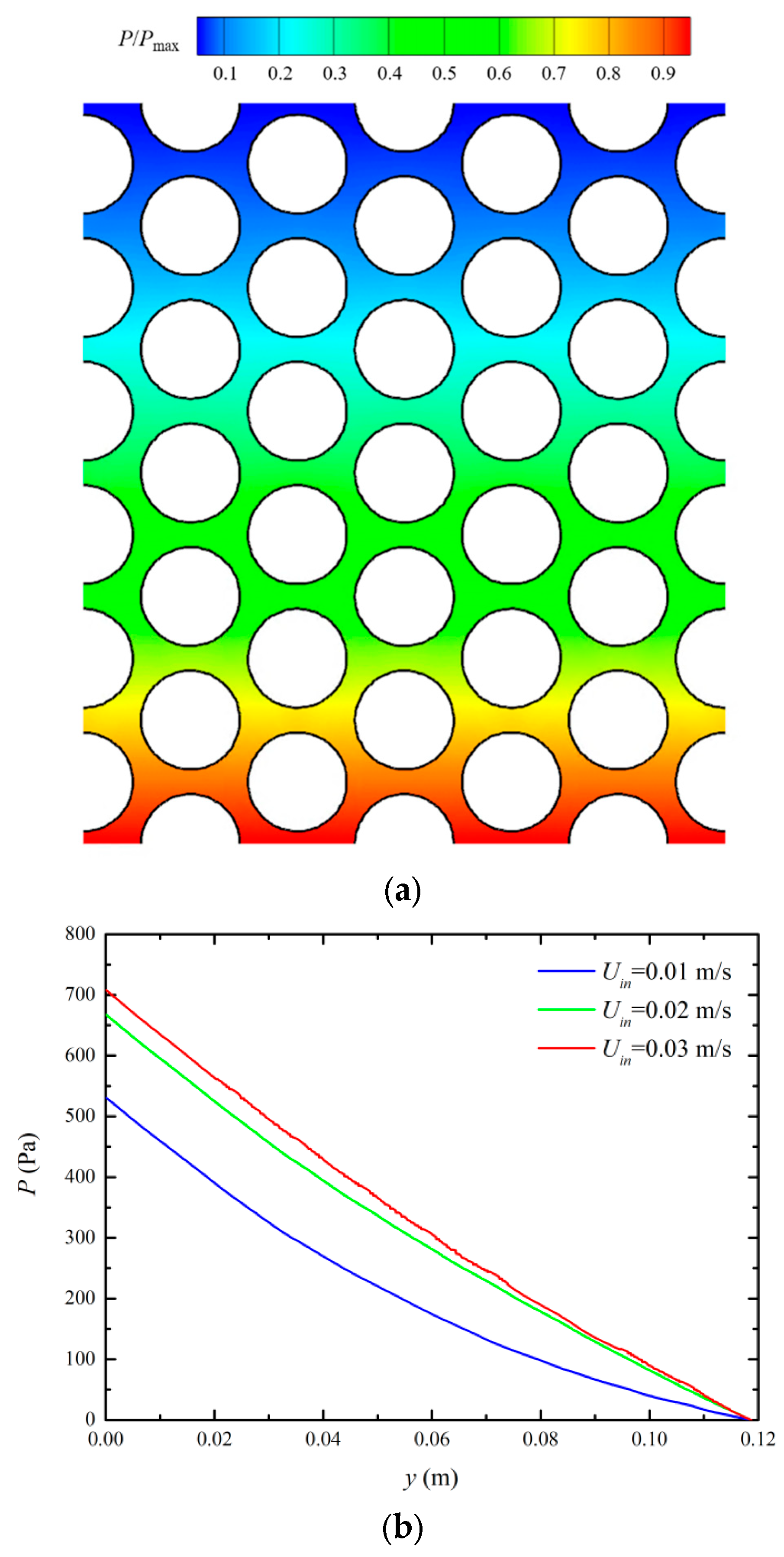
Due to the randomness of turbulent fluctuations and particle motion models (DRW), sampling and statistical analysis methods are used. Figure 3 shows the normalized time-averaged pressure distribution in the local tube bundle region. Along the flow direction, the pressure gradually decreases and the rate of decrease slows down, indicating that the gravity effect of the liquid water is the main factor causing the pressure drop. As the water boils, the proportion of steam increases, resulting in a significant reduction in the gravitational pressure drop in the tube bundle outlet area. Furthermore, as the feedwater flow rate increases, fluid viscous dissipation increases, and the proportion of liquid water in the shell rises, leading to a higher pressure drop.
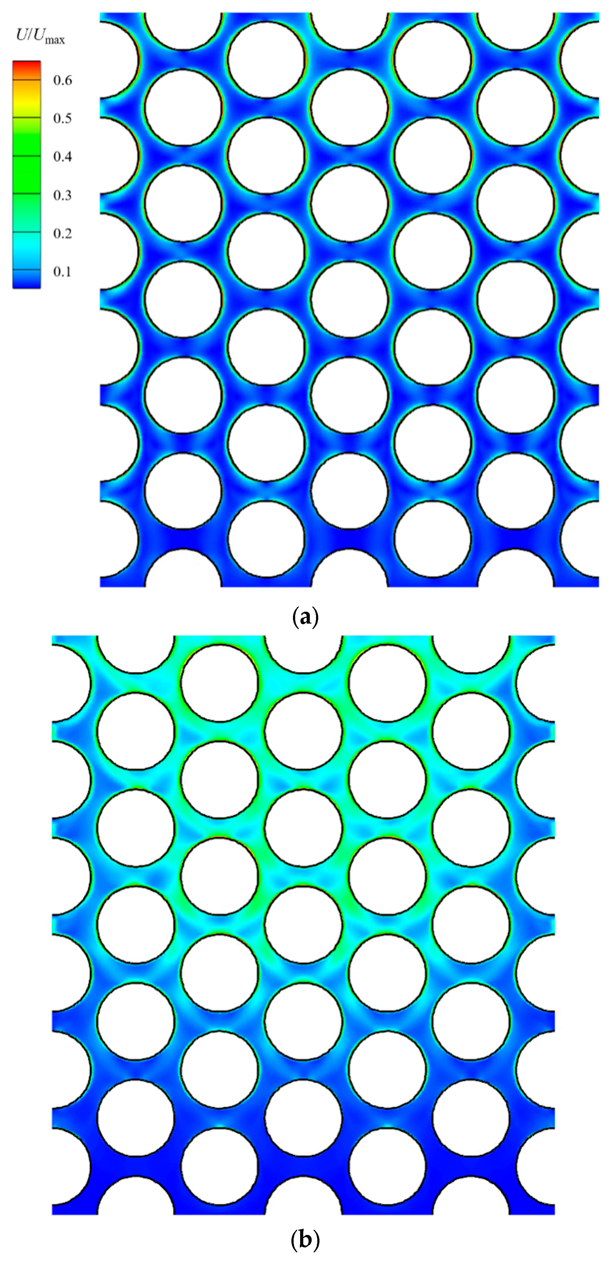
Figure 4a shows the time-averaged velocity distribution of liquid water among the tubes, with sampling averaged over 15 s. As the water flows upwards, it is gradually heated by the high-temperature tubes and undergoes a boiling phase change, resulting in an overall increase in velocity among the tubes. Since the boiling phase change occurs on the surface of the tubes, the surface velocity is high, but low-velocity regions appear at the center of the upstream and downstream faces of each tube. The highest time-averaged velocities are found on the sides of the tubes. Figure 4b shows the root mean square (RMS) fluctuating velocity of the liquid water among the tubes, with sampling averaged over 15 s. As boiling occurs, the proportion of vapor increases, and the velocity difference between the phases becomes larger. Due to the drag of the steam, the liquid water exhibits a higher RMS fluctuation. The central region of the tube bundle shows significantly higher RMS fluctuations compared to the sides. This is attributed to the symmetric boundary conditions applied on the sides, limiting the generation of RMS velocity fluctuations.
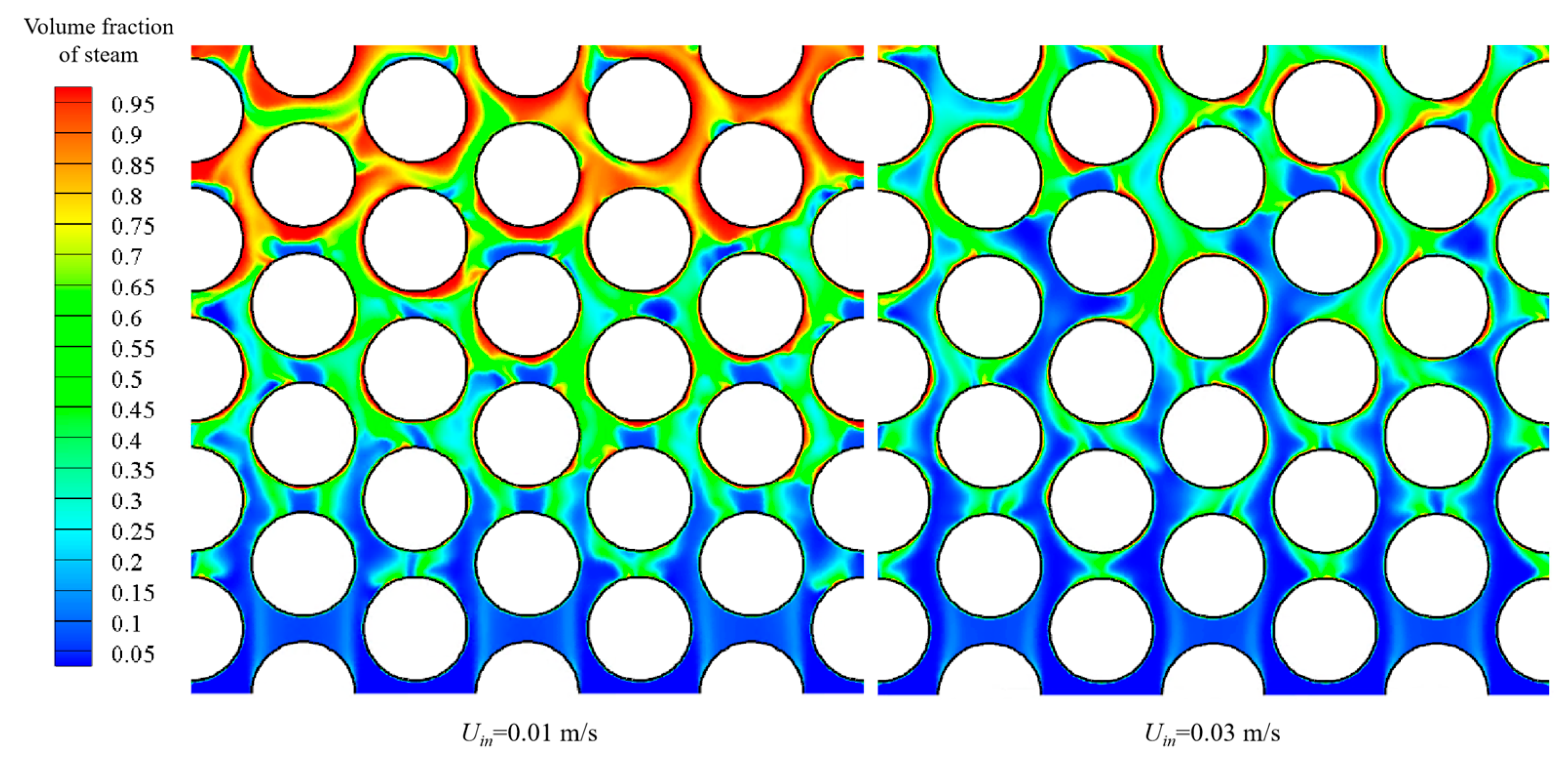
Figure 5 compares the volume fraction distributions of steam generated by boiling within the tube bundle at different feedwater flow rates. As the liquid water enters the tube bundle area, the steam volume fraction is initially low, accumulating only in the wake regions of the initial rows of tubes. As the heating continues, more liquid water boils, gradually filling the entire area. Due to the high-velocity steam generated by boiling, the volume fraction distribution in the shell is uneven and varies significantly over time. At low flow rates, the volume of steam is over 80% at the tube bundle outlet. However, as the feedwater flow rate increases, the steam volume fraction decreases, although the corresponding mass flow rate of the steam increases.
Figure 6 shows the heat flux distribution on the tube surface, with sampling averaged over 15 s. At the calculated wall superheat (≈8 °C), the heat flux is in the order of 105 W/m2, indicating nucleate boiling regimes. According to the RPI boiling model, evaporative heat transfer is dominant during boiling, while single-phase convective heat transfer is negligible. As liquid water is heated by the tube bundle, it is brought to saturation in the upstream region and undergoes a phase change to saturated steam downstream, significantly increasing the latent heat of vaporization. Consequently, the heat flux in the downstream region of each tube is significantly higher than that in the upstream region.

3.2. Particle Deposition

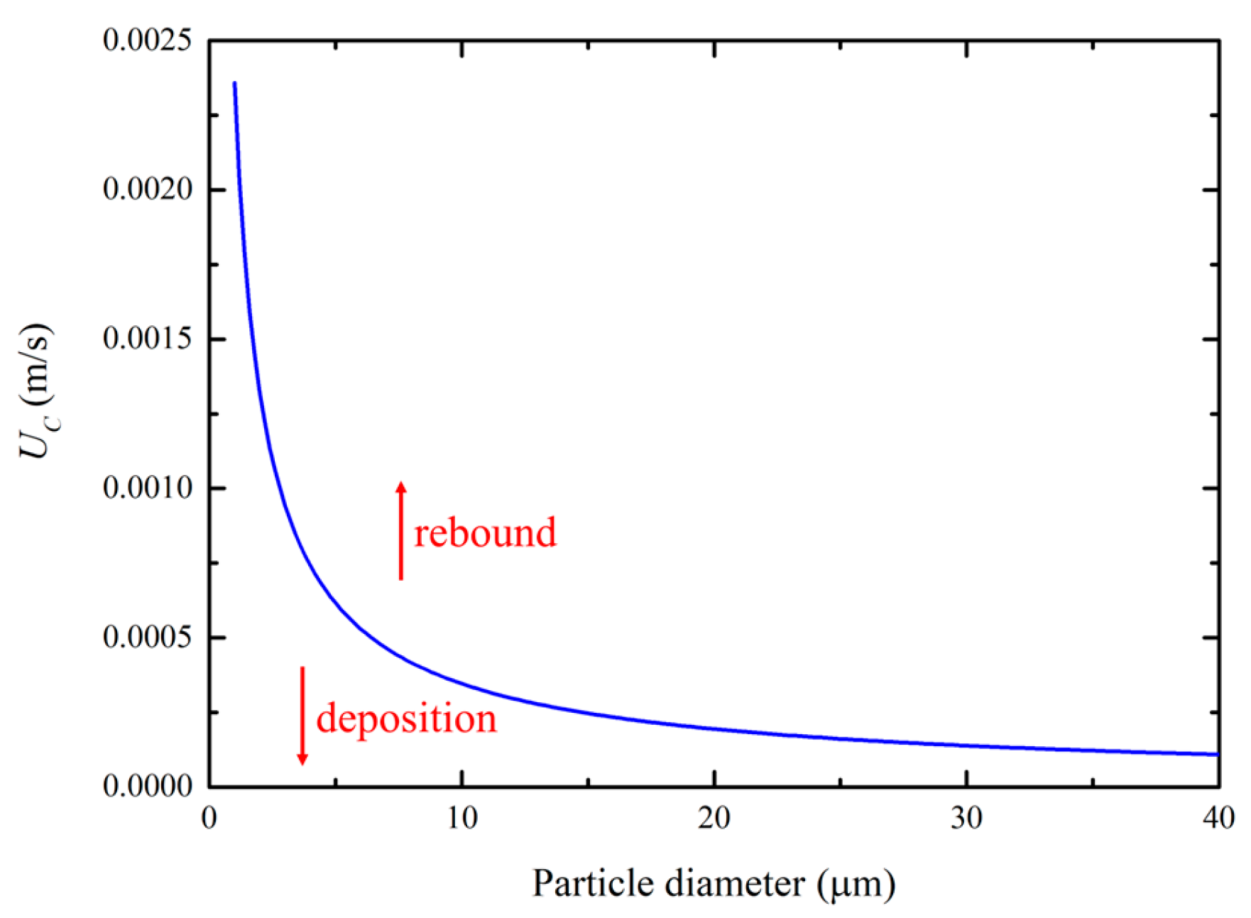
Figure 7 shows the critical deposition velocity curve as a function of the particle diameter, obtained from Equation (6). As the particle diameter increases, the critical deposition velocity decreases. Since particle deposition occurs only when the particle impact velocity is lower than the critical deposition velocity, smaller particles are more likely to deposit compared to larger particles at the same impact velocity.
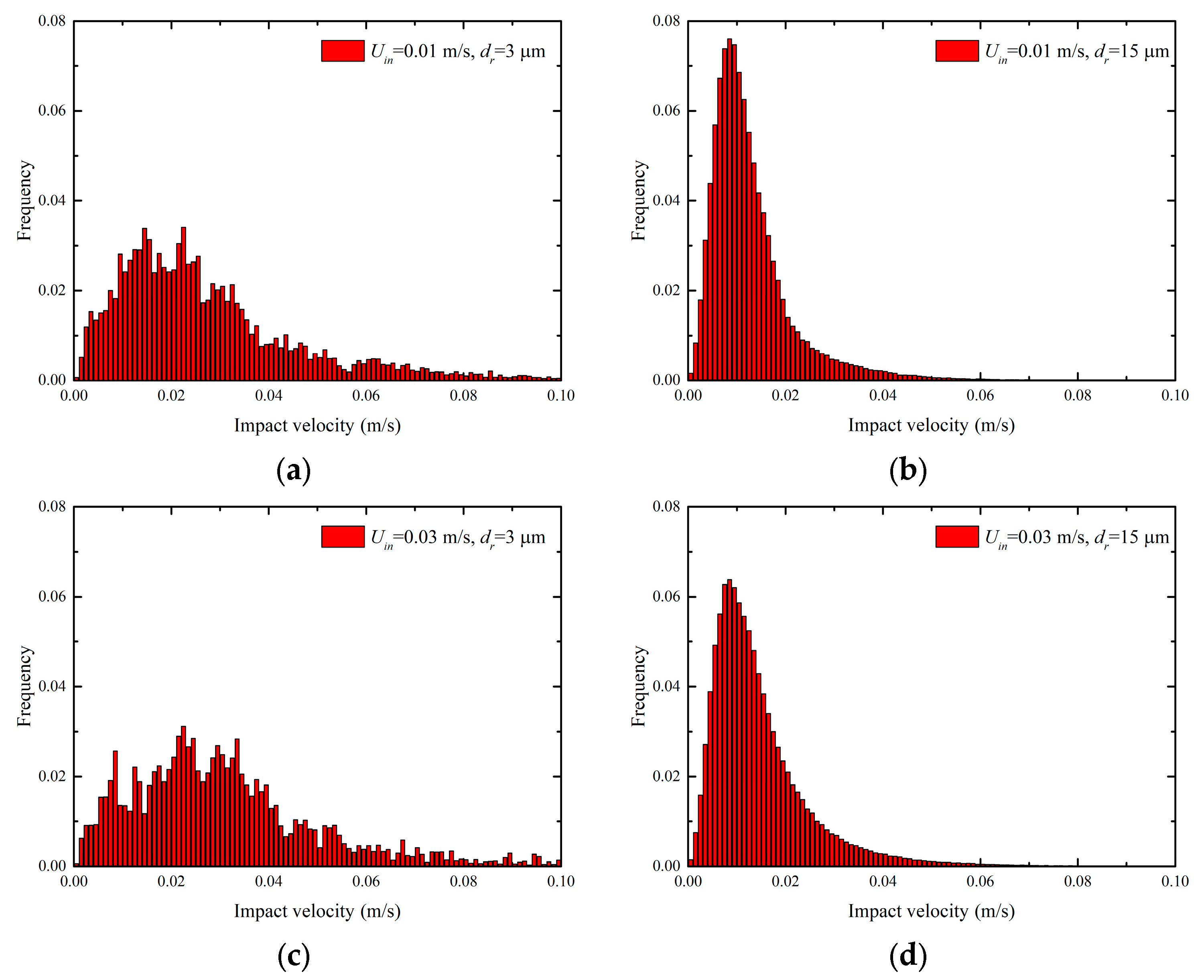
Figure 8 shows the velocity distribution of particles impacting the tube surface. Generally, the impact velocity of particles is higher than the corresponding critical deposition velocity. However, due to multiple impacts and the associated energy dissipation, the probability of deposition increases with continued impacts. The impact velocity distribution of small-diameter particles is broader, while that of large-diameter particles exhibits a normal distribution. Additionally, with the increasing inlet flow velocity and decreasing particle diameter, the average impact velocity on the tube surface decreases. This indicates that small-diameter particles have a better following ability and are prone to the effects of boiling jets, which leads to a more chaotic impact velocity distribution.
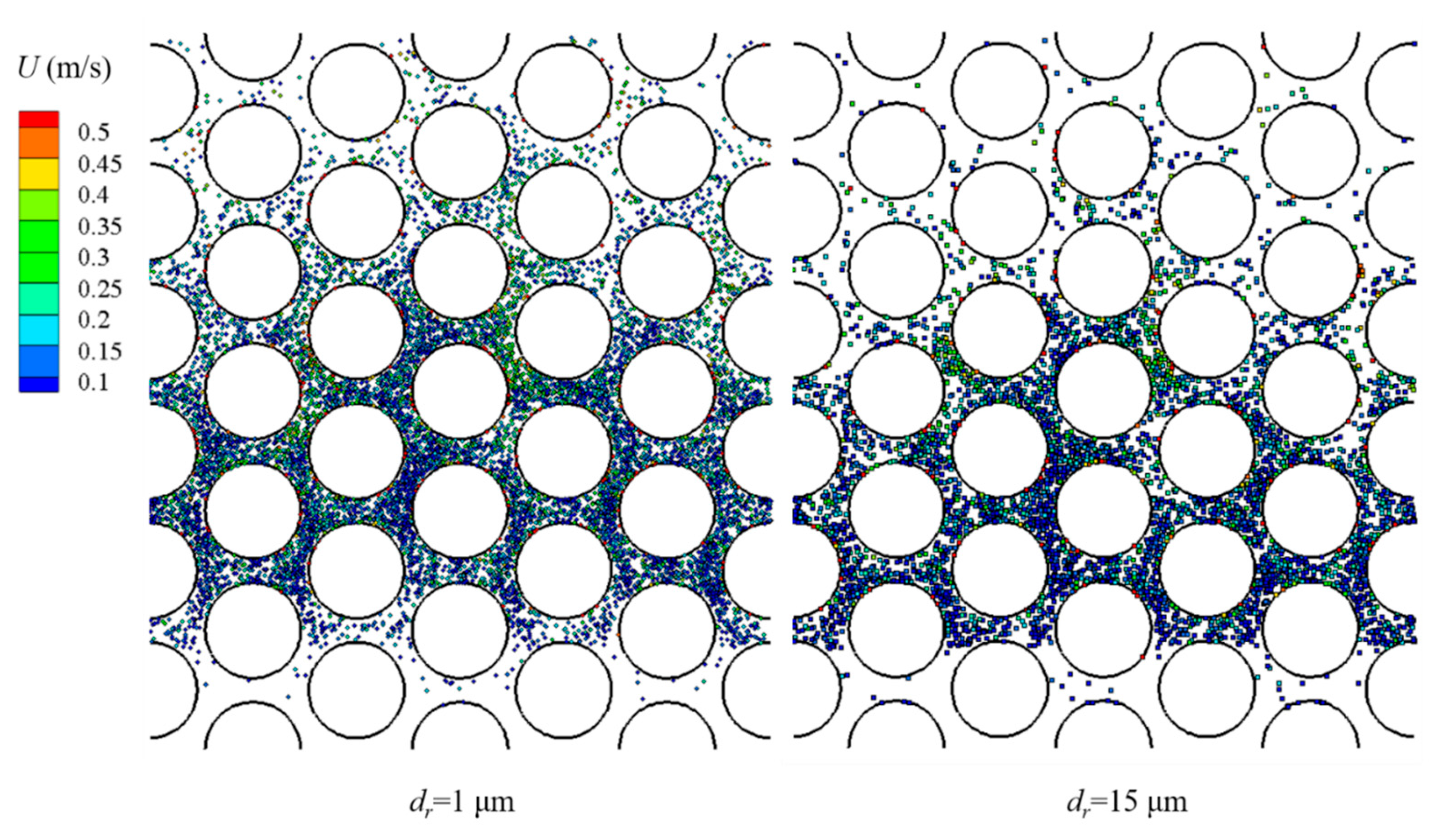
Figure 9 shows the distribution of 1 μm and 15 μm particles among the tubes at 1.6 s after injection. Due to the high-velocity bubbles generated by surface boiling, the maximum particle velocity occurs near the tube surface and is significantly higher than the mainstream velocity. Under the combined influence of the low mainstream velocity and high boiling velocity, both large and small particles disperse within the tube bundle. Over the same flow time, small particles exhibit slightly longer flow distances and have shorter residence times among the tubes.
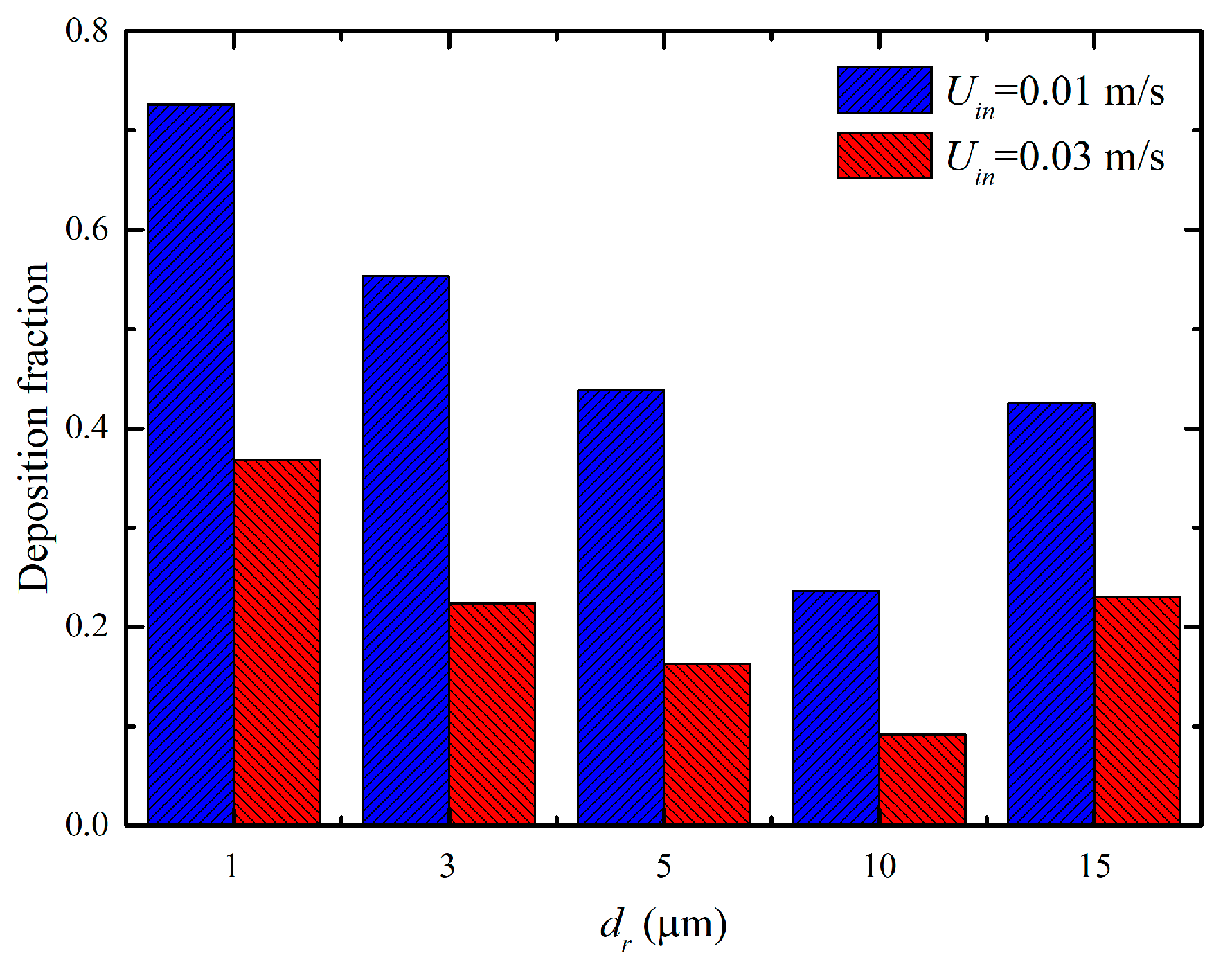
Figure 10 shows the deposition rate of particles of different sizes within the tube bundle under various feedwater flow rates. As the particle diameter increases from 1 μm to 15 μm, the deposition rate initially decreases and then increases. This is because, as the diameter increases (1~10 μm), the corresponding critical deposition velocity decreases, causing more particles to rebound. However, when the particles reach a certain size (>15 μm), gravity exceeds the drag of the fluid, making it difficult for the particles to rise out of the reboiler. As a result, particles undergo multiple collisions with the wall under the influence of gravity until deposition occurs, leading to an increase in the deposition rate. Additionally, increasing the feedwater flow rate directly raises the impact velocity on the wall, thereby reducing the particle deposition rate.
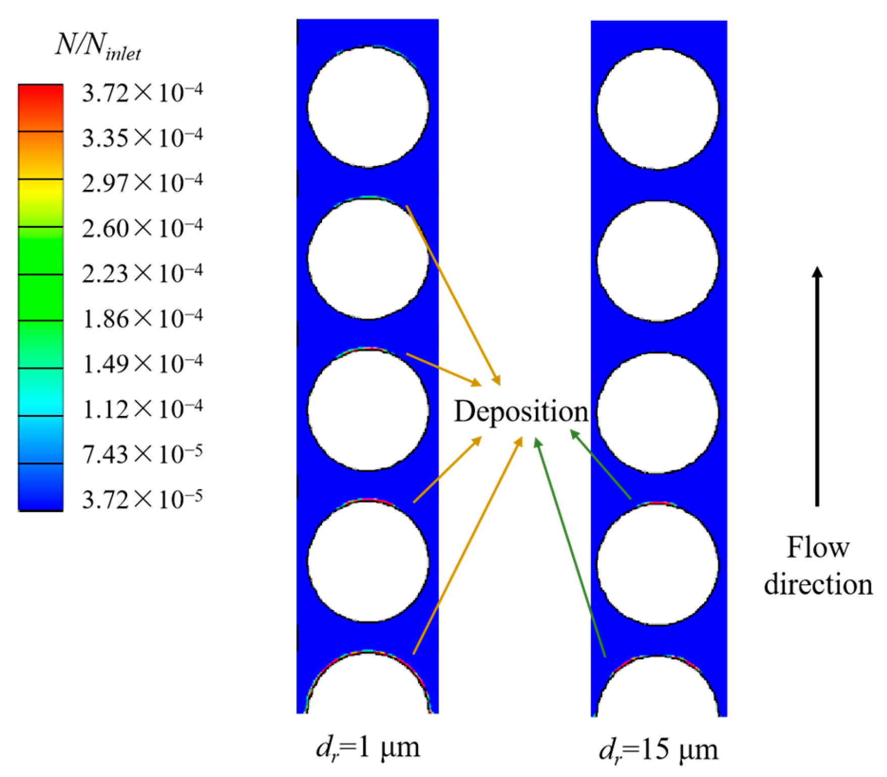
Figure 11 shows the deposition locations of particles on the tube surfaces. Most particles deposit in the low-velocity region at the downstream end of the tubes, with a significantly higher deposition rate on the initial rows of tubes compared to the subsequent rows. Large-diameter particles exhibit noticeable deposition only on the initial rows of tubes due to the low velocity of the liquid water and particles at the inlet end, making it easier for the particles to deposit upon impact.

4. Conclusions

In this study, computational fluid dynamics was used to numerically investigate the flow and heat transfer, as well as particle motion and deposition, in a low-temperature difference kettle reboiler. The main conclusions are as follows.
1. By simulating the nucleate boiling phase change of liquid water on the surface of a local tube bundle in a kettle reboiler, it was found that boiling increases the local velocity and enhances the turbulence intensity, with the maximum steam velocity occurring near the wall. Evaporative heat transfer is dominant during nucleate boiling, with more intense boiling in the downstream regions of each tube. Additionally, with an increased feedwater flow rate, the steam proportion in the reboiler shell decreases, weakening the interaction between the gas and liquid phases.
2. At the same impact velocity, smaller particles have a higher critical deposition velocity and are more prone to deposition. Additionally, due to their lower inertia, small particles follow the high-velocity boiling steam more effectively, exhibiting higher average impact velocities and broader impact velocity distribution curves.
3. Gravity significantly influences the particle trajectories. Despite the similar dispersion of particles of different sizes within the tube bundle due to wall boiling, the residence time of large particles within the reboiler is notably longer. When the particle size reaches a certain threshold, it becomes difficult for the particles to overcome gravity and exit the reboiler under low flow rates. This results in an initial decrease followed by an increase in the particle deposition rate with an increasing particle size, with most particles depositing in the downstream region of the tube bundle.

Author Contributions

X.L.: conceptualization, methodology, writing—original draft preparation. Q.S.: methodology, software, writing—review and editing, visualization. H.T.: resources, funding acquisition. M.Z.: resources, investigation, project administration. W.P.: funding acquisition, data curation, supervision, writing—review and editing. G.Z.: resources, formal analysis, conceptualization. T.F.: project administration, supervision. All authors have read and agreed to the published version of the manuscript.

Funding

This research was funded by the National Natural Science Foundation of China (No. 52176158, Wei Peng) and the Natural Science Foundation of Heilongjiang Province (No. TD2023E005, Hui Tang).

Data Availability Statement

The raw data supporting the conclusions of this article will be made available by the authors on request.

Conflicts of Interest

Authors Xue Liu, Hui Tang and Mingbao Zhang were employed by the company Harbin Boiler Company Limited. The remaining authors declare that the research was conducted in the absence of any commercial or financial relationships that could be construed as a potential conflict of interest.

Nomenclature

CDparticle drag coefficient
CRcorrection factor
drparticle diameter (m)
EYoung’s modulus (Pa)
Fbody force (N/m3)
hspecific enthalpy (J/kg)
ggravitational acceleration vector (m/s2)
Pfluid pressure (Pa)
qheat flux (J/m2)
Rsurface tension (N/m2)
ttime (s)
Ufluid velocity vector (m/s)
vPoisson’s ratio
Greek letters
αvolume fraction
ρdensity (kg/m3)
τrparticle relaxation time
μviscosity (Pa·s)
ωAcombined surface energy (J/m2)

References

  1. Kumar, A.; Jha, H.S. Study, Design and Simulation of Kettle Type Reboiler. Ph.D. Thesis, College of Engineering, UPES, Dehradun, India, 2010. [Google Scholar]
  2. Kumar, A.; Hung, K.; Wang, C. Nucleate pool boiling heat transfer from high-flux tube with dielectric fluid HFE-7200. Energies 2020, 13, 2313. [Google Scholar] [CrossRef]
  3. Li, S.; Li, P.; Zhang, X. Development and Application of High-Flux Heat Exchangers. Chem. Eng. Manag. 2021, 58–59. [Google Scholar] [CrossRef]
  4. Mehralizadeh, A.; Shabanian, S.R.; Bakeri, G. Effect of modified surfaces on bubble dynamics and pool boiling heat transfer enhancement: A review. Therm. Sci. Eng. Prog. 2020, 15, 100451. [Google Scholar] [CrossRef]
  5. Maslovaric, B.; Stevanovic, V.D.; Milivojevic, S. Numerical simulation of two-dimensional kettle reboiler shell side thermal—Hydraulics with swell level and liquid mass inventory prediction. Int. J. Heat Mass Transf. 2014, 75, 109–121. [Google Scholar] [CrossRef]
  6. McNeil, D.A.; Bamardouf, K.; Burnside, B.M.; Almeshaal, M. Investigation of flow phenomena in a kettle reboiler. Int. J. Heat Mass Transf. 2010, 53, 836–848. [Google Scholar] [CrossRef]
  7. Zhang, H.F.; Ahmadi, G. Aerosol particle transport and deposition in vertical and horizontal turbulent duct flows. J. Fluid Mech. 2000, 406, 55–80. [Google Scholar] [CrossRef]
  8. Beghein, C.; Jiang, Y.; Chen, Q.Y. Using large eddy simulation to study particle motions in a room. Indoor Air 2005, 15, 281–290. [Google Scholar] [CrossRef]
  9. Morsi, Y.S.; Tu, J.Y.; Yeoh, G.H.; Wang, W. Principal characteristics of turbulent gas-particulate ow in the vicinity of single tube and tube bundle structure. Chem. Eng. Sci. 2004, 59, 3141–3157. [Google Scholar] [CrossRef]
  10. Fu, S.; Cao, G.; Chen, Q.; Sun, X.; Ou, G.; Zhou, F.; Li, L. Analysis of fly ash deposition blockage mechanism and structure optimization of low temperature economizer. Chem. Ind. Eng. Prog. 2022, 41, 4035–4046. [Google Scholar]
  11. Han, Z.; Lu, H.; Zhao, W.; Wang, Z.; Xiao, Z. Numerical simulation study of particle deposition and heat transfer characteristics in heat transfer pipes with dimpled dimple surface. Energy Environ. Prot. 2023, 37, 201–208. [Google Scholar]
  12. Zhuang, Z.; Wang, G.; Xu, J.; Zhang, C.; Zhang, C. Study on deposition characteristics of particulate fouling in U-shaped sewage heat exchange tubes. Heat. Vent. Air Cond. 2023, 53, 166–172. [Google Scholar]
  13. Xu, Z.; Li, J.; Han, Z.; Yang, X. Investigation of deposition characteristics on tube-bundle heat exchanger with an improved ash particle model. Powder Technol. 2023, 413, 118027. [Google Scholar] [CrossRef]
  14. Zhang, Z.; Tian, H.; Ding, Z.; Zhang, Y.; Wang, Z. Influence and Optimization of Soot Particles Deposition on Tube Heat Exchanger Performance. J. Eng. Thermophys. 2023, 44, 769–780. [Google Scholar]
  15. Liu, K.; Wei, B.; Zhang, Y.; Wang, J.; Chen, L.; Liu, N. Numerical simulation of particle deposition on wall surfaces of heat exchange tube bundles. Coal Convers. 2023, 46, 95–102. [Google Scholar]
  16. Li, M. Numerical Study of Impurity Distribution in Two-Phase Flow on the Secondary Side of Steam Generator. Master’s Thesis, Harbin Engineering University, Harbin, China, 2023. [Google Scholar]
  17. Zou, J.; Jiang, J.; Li, Q.; Yang, X.; Chu, H.; Di, X.; Zhou, J. Study on Heat Transfer Characteristics and Ash Wear of Elliptical Finned Tubes. Boil. Technol. 2024, 55, 7–14. [Google Scholar]
  18. Akbari, V.; Borhani, T.; Nejad, G.; Shamiri, A.; Shafeeyan, M. Computational fluid dynamics modeling of gas-solid fluidized bed reactor: Influence of numerical and operating parameters. Exp. Comput. Multiph. Flow 2024, 6, 85–125. [Google Scholar] [CrossRef]
  19. Sun, Q.; Liu, B.; Wang, X.; Peng, W.; Shi, L. Fluid-structure coupling for particle deposition-resuspension predictions in tube bundle heat exchangers based on dynamic mesh method. Chem. Eng. Sci. 2024, 297, 120313. [Google Scholar] [CrossRef]
  20. Lu, H.; Wang, Y.; Li, H.; Zhao, W. Numerical Simulation of Turbulent Structure and Particle Deposition in a Three-Dimensional Heat Transfer Pipe with Corrugation. Energies 2024, 17, 321. [Google Scholar] [CrossRef]
  21. McNeil, D.A.; Burnside, B.M.; Miller, K.M.; Tarrad, A.H. A comparison between HIGHFLUX and plain tubes, boiling pentane in a horizontal kettle reboiler. Appl. Therm. Eng. 2002, 22, 803–814. [Google Scholar] [CrossRef]
  22. ANSYS Inc. Ansys Fluent Theory Guide; ANSYS Inc.: Canonsburg, PA, USA, 2021. [Google Scholar]
  23. Oliani, S.; Casari, N.; Pinelli, M.; Carnevale, M. Simulation of Particle Trajectories in Gas Turbine Components and Assessment of Unsteady Effects Using an Efficient Eulerian-Lagrangian Technique. Energies 2023, 16, 2810. [Google Scholar] [CrossRef]
  24. Kurul, N.; Podowski, M.Z. On the modeling of multidimensional effects in boiling channels. In Proceedings of the 27th National Heat Transfer Conference, Minneapolis, MN, USA, 28–31 July 1991. [Google Scholar]
  25. Menter, F.R. Two-Equation Eddy-Viscosity Turbulence Models for Engineering Applications. AIAA J. 1994, 32, 1598–1605. [Google Scholar] [CrossRef]
  26. Gao, N.; Niu, J.; He, Q.; Zhu, T.; Wu, J. Using RANS turbulence models and Lagrangian approach to predict particle deposition in turbulent channel flows. Build. Environ. 2012, 48, 206–214. [Google Scholar] [CrossRef]
  27. Sun, Q.; Wang, X.; Shi, L.; Peng, W. Aerodynamic Drag of Rod-shaped Particles Near-wall in Nuclear Reactor. At. Energy Sci. Technol. 2023, 57, 2067–2076. [Google Scholar]
  28. Liu, P.; Liu, W.; Gong, K.; Han, C.; Zhang, H.; Sui, Z.; Hu, R. Numerical study on particulate fouling characteristics of flue with a particulate fouling model considering deposition and removal mechanisms. Energies 2022, 15, 8708. [Google Scholar] [CrossRef]
  29. Kim, O.V.; Dun, P.F. A microsphere-surface impact model for implementation in computational fluid dynamics. J. Aerosol Sci. 2007, 38, 532–549. [Google Scholar] [CrossRef]
  30. Sun, Q.; Chen, T.; Peng, W.; Wang, J.; Yu, S. A numerical study of particle deposition in HTGR steam generators. Nucl. Eng. Des. 2018, 332, 70–78. [Google Scholar] [CrossRef]
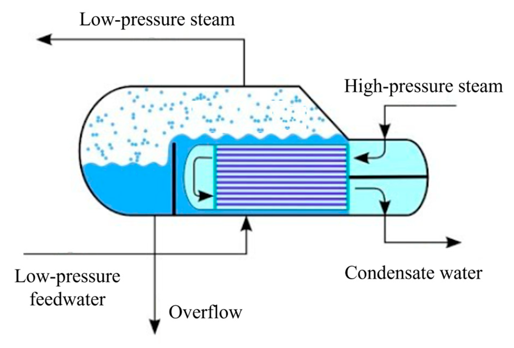
Figure 1. Schematic diagram of the structure and process flow of a kettle reboiler.
Energies 17 04183 g001
Figure 2. Computational zone of tube bundle cross-section.
Energies 17 04183 g002
Figure 3. Pressure field: (a) normalized pressure contour, (b) pressure curves at different flow rates.
Energies 17 04183 g003
Figure 4. Liquid phase normalized velocity contour: (a) time-averaged velocity, (b) root mean square deviation of velocity.
Energies 17 04183 g004
Figure 5. Volume fraction contour of vapor phase under different flow rates.
Energies 17 04183 g005
Figure 6. Heat flux distribution on the wall.
Energies 17 04183 g006
Figure 7. Critical deposition velocity curve.
Energies 17 04183 g007
Figure 8. Particle impact velocity distribution on the wall: (a) dr = 3 μm, Uin = 0.01 m/s; (b) dr = 15 μm, Uin = 0.01 m/s; (c) dr = 3 μm, Uin = 0.03 m/s; (d) dr = 15 μm, Uin = 0.03 m/s.
Energies 17 04183 g008
Figure 9. Particle motion around tube bundle.
Energies 17 04183 g009
Figure 10. Particle deposition curve under different diameters.
Energies 17 04183 g010
Figure 11. Particle deposition distribution on the tube.
Energies 17 04183 g011
Table 1. Working conditions and properties.
TypeParameterValue
Working
conditions
Inlet velocity (m/s)0.01–0.03
Inlet temperature (K)540
Particle diameter (μm)1~15
Pressure (MPa)5.5
Wall temperature (K)550.15
FluidDensity (kg/m3)767.87 (liquid phase)/28.06 (gas phase)
Dynamic viscosity (Pa·s)9.75 × 10⁻⁵ (liquid phase)/1.83 × 10−5 (gas phase)
Thermal conductivity (W/m/K)0.596 (liquid phase)/0.057 (gas phase)
Surface tension (N/m)0.021
Boiling point (K)543.12
Particles/
wall
Density (kg/m3)7970
Young’s modulus (GPa)190
Poisson’s ratio0.27
Surface energy (J/m2)2.56
Disclaimer/Publisher’s Note: The statements, opinions and data contained in all publications are solely those of the individual author(s) and contributor(s) and not of MDPI and/or the editor(s). MDPI and/or the editor(s) disclaim responsibility for any injury to people or property resulting from any ideas, methods, instructions or products referred to in the content.