Review

A Review on Key Technologies and Developments of Hydrogen Fuel Cell Multi-Rotor Drones

1
China Coal Technology and Engineering Group Corp., Beijing 100020, China
2
Department of Energy and Power Engineering, Tsinghua University, Beijing 100084, China
*
Authors to whom correspondence should be addressed.
Energies 2024, 17(16), 4193; https://doi.org/10.3390/en17164193
Submission received: 17 June 2024 / Revised: 2 August 2024 / Accepted: 20 August 2024 / Published: 22 August 2024

Abstract

:
Multi-rotor drones, a kind of unmanned equipment which is widely used in the military, commercial consumption and other fields, have been developed very rapidly in recent years. However, their short flight time has hindered the expansion of their application range. This can be addressed by utilizing hydrogen fuel cells, which exhibit high energy density, strong adaptability to ambient temperature, and no pollution emissions, as the power source. Accordingly, the application of hydrogen fuel cells as the power source in multi-rotor drones is a promising technology that has attracted significant research attention. This paper summarizes the development process of hydrogen fuel cell multi-rotor drones and analyzes the key obstacles that need to be addressed for the further development of hydrogen fuel cell multi-rotor drones, including structural light weight, hydrogen storage methods, energy management strategies, thermal management, etc. Additionally, prospects for the future development of hydrogen fuel cell multi-rotor drones are presented.

1. Introduction

Depending on their structure, drones can be divided into three types: fixed-wing drones, single-rotor drones, and multi-rotor drones [1,2]. Compared to the other two types of drones, multi-rotor drones can take off and land vertically, hover in the same place for a long time [3], and exhibit a simple structure and strong maneuverability [4], making them very suitable for aerial photography [5,6], patrol inspection [7,8], precision agriculture [9,10], and other types of missions in various fields, including commercial consumption or engineering applications. Taking the application of multi-rotor drones in precision agriculture as an example, they can be used for air spraying [11,12,13,14] and agricultural information monitoring. The precise spraying of pesticides and fertilizers by these drones can effectively improve the quality and yield of crops. Additionally, the low altitude-sensing systems (LARS) of multi-rotor drones can provide higher-resolution images compared to satellites, thereby reducing the loss of predictability in the process of crop production and preventing safety issues during operation [15]. Accordingly, multi-rotor drones are currently the mainstream products in the drone market.
Despite their promising advantages, the short flight time of multi-rotor drones is one of the key factors limiting their further development [16]. Lithium batteries are used as the power source in most of the existing mature multi-rotor drones. However, the energy density of lithium batteries is 130–200 Wh/kg, whereas the power loading (the weight that can be lifted by unit power) of multi-rotor drones is typically approximately 10 g/W, which limits the battery weight that can be handled by the drone [17], making the flight time of multi-rotor drones powered by lithium batteries very short (typically within 40 min) [18]. Therefore, battery replacement is required during the frequent start-and-stop operations of these drones. In contrast, the energy density of fuel cell hybrid systems is 250–540 Wh/kg [19], indicating that fuel cells can power at least twice the flight time that can be powered by lithium batteries at the same weight, making them very suitable for long-time flight [20]. This is of great significance for improving the endurance of multi-rotor drones, improving charging efficiency, and reducing the labor intensity of operators. Figure 1 shows a Ragone plot illustrating the energy density vs. power density of various power sources, and the plot indicates the significantly higher energy density of fuel cells compared to other power sources. In addition to the previously mentioned limitations of lithium batteries as the power source of drones, there are some other disadvantages [21]: (1) lithium batteries easily short circuit or overcharge, making them unsuitable for long-term use; (2) lithium batteries experience a large temperature increase during operation, which may result in the burning of the drone if the temperature increases to a critical point; (3) easy detection by infrared detectors owing to the heat generated by the lithium battery during the flight of the drone, thus limiting the application of drones in the military field; and (4) negative impact on the environment during the recycling process. In contrast, the service life of fuel cells is approximately three times that of lithium batteries [22], and fuel cells only discharge water during operation, making them superior to lithium batteries in terms of environmental impact. Consequently, drones powered by fuel cells have emerged as a hot technology being researched in various countries.
The types of fuel cells commonly used are proton exchange membrane fuel cells (PEMFC), direct methanol fuel cells (DMFC), and solid oxide fuel cells (SOFC). Their operating temperature, reaction principles, advantages, and disadvantages are compared in Table 1. Among these, PEMFCs exhibit a light weight, high energy density, low operating temperature, and fast start-up, making them the most widely used fuel cells in drones [24].
As shown in Figure 2, a typical PEMFC structure is divided into a cathode flow channel, anode flow channel, gas diffusion layer, catalytic layer, and proton exchange membrane [28]. Hydrogen diffuses into the gas diffusion layer after passing through the anode flow channel, loses electrons under the action of the catalytic layer, and transfers protons to the cathode side through the proton exchange membrane. Oxygen diffuses into the gas diffusion layer after passing through the cathode channel and combines with the protons passing through the proton exchange membrane and the electrons from the external circuit to form water under the influence of the catalyst. Through these reactions, a fuel cell can form a continuous current between the cathode and anode. Typically, the cathode and anode flow channels are designed on the front and back of the same conductive plate to form a bipolar plate [29], and the gas diffusion layer, the catalytic layer, and the proton exchange membrane are combined to form the membrane electrode assembly (MEA) [30]. This design enables the stacking and combination of the fuel cell stack in a “bipolar plate-membrane electrode-bipolar plate” configuration.
During operation, PEMFCs generate a considerable amount of heat, as shown in Figure 3. The heat generated accounts for 45% of the total hydrogen energy, which can result in the drying out of the membrane electrode and the subsequent deterioration of the performance of the cell if the heat is not discharged in time [31]. Consequently, a cooling system is an important part of fuel cells. Depending on the cooling methods, PEMFCs can be divided into water-cooled type and air-cooled types [32]. Compared to water-cooled PEMFCs, air-cooled PEMFCs cool the stack via air purging without complicated auxiliary systems, making the entire system simpler and lighter. This is particularly advantageous in low-power devices, such as drones, which require less heat dissipation. Depending on their structure, air-cooled PEMFCs can be further subdivided into three types: area air-cooled [33], edge air-cooled [34,35], and open-cathode type [36]. In the open-cathode type, the cathode channel is exposed to the atmosphere, and the flowing air simultaneously provides the oxygen required for the cathode reaction and cools the stack through fan suction. This type of fuel cell combines the advantages of simple structure and large power range, making it the most widely used and advanced fuel cell among the three types of air-cooled PEMFCs.
As illustrated in Figure 4, a typical configuration of an open-cathode air-cooled fuel cell power system primarily comprises a proton exchange membrane fuel cell (PEMFC) stack, fan, hydrogen cylinder, hydrogen regulator, lithium battery, and control module. The PEMFC stack serves as the site for electrochemical reactions that generate electricity. The fan facilitates airflow to supply oxygen for the PEMFC stack’s reactions while simultaneously cooling the stack. The hydrogen cylinder is utilized for storing hydrogen gas, whereas the hydrogen regulator reduces high-pressure hydrogen gas to low pressure and controls its flow. The lithium battery regulates and balances power fluctuations during operation of the fuel cell power system and provides auxiliary device power supply such as fans. The control module primarily manages energy allocation between the fuel cell and lithium battery.
In summary, the open-cathode PEMFC has the advantages of a high energy density, low noise, and no pollution, and is an ideal power source for multi-rotor drones. This paper presents the development history and technical status of hydrogen fuel cell multi-rotor drones and analyzes the key technologies that need further research in the field of hydrogen fuel cell multi-rotor drones.

2. Development and Application of Hydrogen Fuel Cell Multi-Rotor Drones

Air-cooled fuel cells are often used in small mobile devices, such as bicycles, forklifts, and drones. Among these devices, drones are not only the most technically difficult devices for fuel cell applications, but also the devices that best demonstrate the superiority of fuel cells.
Research on hydrogen fuel cell multi-rotor drones just started in recent years. In 2015, EnergyOr, located in Montreal, Canada, developed H2Quad series drones powered by its EPOD fuel cell [38]. This drone can fly for 2 h with a load of 1 kg, and its effective flight radius is three times that of battery-powered multi-rotor drones [39]. Similarly, Intelligent Energy (Loughborough, UK), tested the DJI Matrice 100 drone equipped with its fuel cells in 2015 and observed that the flight time of the drone can reach up to 1 h. Additionally, in 2015, HES (Horizon Energy Systems Co., Ltd., Singapore) launched the Hycopter fuel cell drone for large-scale industrial maintenance and inspection [40]. This drone can fly for 3 h with a 12 L (3.5 kg) gas cylinder, and they implemented a highly lightweight design for each key component of its power system. Wuhan Zhongyu Power Co., Ltd. (Wuhan, China) released a six-rotor drone, “Ranger”, equipped with its fuel cell system, HyLite1200, in 2015 [41]. The drone uses a 9 L/30 MPa high-pressure gas cylinder and achieved a flight time of 3 h 30 min during the field test, setting a record for the flight time of drones at the time.
The world’s first manufactured hydrogen fuel cell multi-rotor drone is HYDrone-1800 [42,43], which was released by MMC (MicroMultiCopter Aero Technology Co., Ltd., Shenzhen, China) in 2016. The fuselage of HYDrone-1800 is composed of carbon fiber materials and adopts a 6-axis design. It has a wheelbase of approximately 1.8 m, a maximum load of 25 kg, and a maximum flight radius of 100 km. The drone can fly continuously for 270 min with a 14 L gas cylinder and is suitable for inspection operations in various outdoor environments. In 2017, FlightWave (FlightWave Aerospace Systems Inc., Santa Monica, CA, USA) developed a multi-rotor drone named Jupiter-H2, powered by Intelligent Energy’s 650 W fuel cell [44]. The Jupiter-H2 uses a narrow profile 70 cm fuselage and is equipped with 8 high thrust engines, and achieved a flight time of above 2 h. Some early hydrogen fuel cell multi-rotor drones are shown in Figure 5.
Owing to their long flight time and good environmental protection, the application of fuel cell drones has been gradually promoted. In 2018, ISS Aerospace (Berkshire, UK) launched a drone named Sensus4 powered by Intelligent Energy’s air-cooled fuel cell platform IE-Soar 800 W [45], and also launched Sensus6 [46], powered by IE-Soar 2400 W, in 2019. These two drones are equipped with light gas cylinders produced by AMS, with payloads of 1.5 and 8 kg, respectively. The main application fields of these drones include the energy, environment, and military industries. In 2018, HES commercially released Hycopter [47], and the fuel cell system of this drone has an energy density of 700 Wh/kg and a power density of more than 1 W/g. Additionally, Hycopter uses a hydrogen regulator with a weight of only 140 g, has a flight time of 3.5 h, and can carry high-speed precision cameras and various sensors for longer periods. Skycorp (Skycorp Technologies, Tartu, Estonia) introduced the e-Drone Zero in the same year, which is a fuel cell quadcopter drone equipped with AI capabilities [48]. The drone was equipped with an Intelligent Energy’s IE-Soar 800 W fuel cell and an AI operating system that can perform complex operations and provide security measures, such as obstacle avoidance based on machine vision. In 2019, the drone photography company BATCAM (Essex, UK) applied the fuel cells of Intelligent Energy to a multi-rotor drone [49], making the drone’s flight time reach 70 min with a load of 5 kg, whereas the flight time of multi-rotor drones using lithium batteries from the same company was only 12 min. In 2020, Nordic Unmanned (Sandnes, Norway) installed HES’s 2000 W air-cooled fuel cell system [50] on its Staaker BG-200 drone, and after a successful test flight, the company planned to further apply the drone to logistics, search, rescue, and inspection. Some fuel cell multi-rotor drones used for inspection are shown in Figure 6.
To further improve the flight time of fuel cell multi-rotor drones, researchers are attempting to increase the hydrogen-carrying capacity of drones by changing the hydrogen storage method. Based on Intelligent Energy’s IE-Soar 800 W fuel cell in 2019, Meta Vista Inc., (Seoul, South Korea) equipped a drone with a 6 L liquid hydrogen tank as shown in Figure 7, increasing the energy density of the power source to 1865 Wh/kg and increasing the flight time of the drone beyond 12 h [51]. However, owing to the high cost of using liquid hydrogen, the difficulty of storage, and the imperfection of related technologies, other drone companies have not attempted this technical route, and the gaseous hydrogen storage method is still the most widely used hydrogen storage method in multi-rotor drones.
With the advancement of technology, fuel cells for drones are gradually being commercialized and serialized. Currently, the companies with the most in-depth and advanced research on fuel cell drones include the Intelligent Energy (Loughborough, UK) and DMI (Doosan Mobility Innovation Co., Ltd., Yongin-si, Gyeonggi-do, South Korea), and both companies can independently develop air-cooled fuel cell stacks and power systems for drones. The common features of drones manufactured by these companies include high integration and modularization. Intelligent Energy’s IE-Soar series of fuel cells for drones includes currently one of the lightest fuel cell modules in the world, and this company has achieved a high stack power density exceeding 800 W/kg, including IE-Soar 650 W [52], IE-Soar 800 W [53], and IE-Soar 2400 W [54]. These modules can increase the weight and space that the auxiliary equipment can occupy, thereby prolonging the flight time of the drone. Figure 8 shows an IE-Soar 650 W fuel cell module and a drone powered by the IE-Soar 650 W. To enhance the series connection of fuel cell stacks, Intelligent Energy developed a power path module (PPM) [55,56] adapted to IE-Soar 650 W and IE-Soar 800 W. This module can simultaneously distribute hydrogen and transfer energy and combine various fuel cell power modules (FCPM) in different ways, and this plays a very important role in expanding the power range of drones. Based on the PPM module, a project named Zephyr used two IE-Soar 800 W fuel cells on the vertical take-off and landing drone of the US Army [57].
The most significant feature of the products of DMI is the high integration. The components of the entire fuel cell systems manufactured by this company, including the gas cylinder and the auxiliary power source, are integrated in the same pack, allowing users to easily match the drones they need. Representative fuel cell packs of DMI include DP20 [58], DP30 [59], and DM30 [60]. The DP30 has a power of 2600 W and is considered the world’s largest power fuel cell power pack module. The DM30 is the module removing housing from DP30. Additionally, DMI has developed ultra-light bipolar plates and a special stack structure for drones with a highly lightweight fuel cell pack while ensuring the durability of the fuel cell and the uniformity of the output performance of the battery. As shown in Figure 9, the overall weight of DP30, consisting of a 10.8-L cylinder, is only 12 kg. Based on its own fuel cell pack, DMI has successively developed a series of drones, such as DT20, DS30, and DT30. Two DP30 modules have been combined to produce a 5.2 kW hydrogen fuel cell system, which was used to power a 39 kg medium-sized hexacopter, and the flight test results proved the feasibility of the 5.2 kW fuel cell system medium-sized hexacopter to perform stable flights [61]. Currently, DMI’s innovative drones have been applied in many fields, such as sea rescue, wind power inspection, road surface inspection, pipeline inspection, and logistics distribution [62].
Ballard (Burnaby, BC, Canada) launched FCair-600 and FCair-1200, two fuel cell systems for drones (Figure 10) [63]. These FCair series fuel cell systems utilize water-cooled fuel cell stacks, which significantly increase the overall weight of the system compared to air-cooled fuel cell systems of the same power; therefore, water-cooled fuel cell stacks have not been widely used in multi-rotor drones.
China is the largest producer and consumer of hydrogen fuel cell drones in the world at present. As shown in Figure 11, in 2022, a total of 659 hydrogen fuel cell drones were produced globally, of which China accounted for 27.2%, and a total of 639 hydrogen fuel cell drones were sold, of which China accounted for 27.6%. Many Chinese companies have advanced manufacturing technology for hydrogen fuel cell drones. Xinyan Chuangneng Technology Co., Ltd. (Beijing, China) launched a six-rotor hydrogen fuel cell drone. The drone can fly continuously for 331 min with a 19 L/35 MPa light gas cylinder, setting a record for the flight time of a fuel cell drone based on a compressed gaseous hydrogen storage method [64]. Additionally, the drone also demonstrated that China is at the forefront of hydrogen fuel cell fabrication in the world. Hydrogen Craft Co., Ltd. (Huzhou, China) another hydrogen drone company from China, developed Hercules ACFC-48-1700 and Hercules ACFC-48-2700 air-cooled stacks specially for drones. The stacks utilize carbon nano-microporous stacking technology and exhibit a power density of approximately 700 W/kg. This same company manufactured the Hydrocopter-04 drone, which is based on two 1700 W air-cooled stacks. This drone can fly for up to 4.5 h without load, and has been tested in various fields. With the continuous advancement in hydrogen energy drone technology, China launched the national standard “Hydrogen Fuel Cell Power System for Unmanned Aerial Vehicles” in June 2020 [65], which is the world’s first national hydrogen fuel cell standard for drones.
Some hydrogen fuel cell multi-rotor drones and their parameters are listed in Table 2.

3. Research Status of Key Technologies

3.1. Lightweight Design

Limited by the power loading of the propeller, when the power of the drone is constant, the total take-off weight of the drone is limited [74], thus necessitating a reasonable weight distribution of each hardware in a drone. The flight time of fuel cell drones mainly depends on the amount of hydrogen carried by the drone, that is, if the weight of each hardware can be reduced, the capacity of the gas cylinder can be increased to carry more hydrogen. Thus, the lightweight design of hydrogen fuel cell system hardware and the drone structure are important technical routes to improve the flight time of hydrogen fuel cell drones.

3.1.1. Bipolar Plates

The main hardware of hydrogen fuel cell multi-rotor drones includes fuel cell stacks, hydrogen cylinders, regulators, and fuselages. The key components of the fuel cell stacks are bipolar plates, which account for more than 80% of the entire weight of the fuel cells [75], so the lightweight design of bipolar plates is the key to realizing the light weight of fuel cell systems. To reduce the weight of the bipolar plate, its materials need to be optimized. Common bipolar plate materials include graphite materials, metal materials, and composite materials [76].
Graphite materials have long been used in the manufacturing of bipolar plates [77] owing to their low density, good corrosion resistance, and good affinity with carbon fiber diffusion layers [78]. However, owing to their low strength and strong brittleness, graphite bipolar plates are typically fabricated with a high thickness to meet the strength requirements of the stack, resulting in the large volume and mass of the stack. Although some scholars have reduced the thickness of bipolar plates by improving the structure of graphite plates [79,80], graphite materials are still inferior to the other two materials in terms of lightweight design.
Composite bipolar plates are bipolar plates fabricated by the injection molding of a polymer resin with conductive fillers, such as graphite [81,82,83]. The specific strength of composite bipolar plates is higher than that of graphite bipolar plates; thus, they exhibit significant advantages in terms of lightweight design, but owing to their complicated manufacturing process and high cost, composite bipolar plates are currently not widely used. With the development of 3D printing, researchers are attempting to adapt this technology to simplify the manufacturing process of composite bipolar plates. For example, a previous study [84] developed and fabricated a lightweight stack based on the Horizon 100 W fuel cell stack. The bipolar plates of the stack were fabricated with PETG material using 3D printing technology, and the bipolar plates were endowed with conductivity because PETG is an electrically insulative material. The results revealed that, through the redesign of materials and processes of key components, such as bipolar plates, the total weight of the original 100 W fuel cell stack was reduced from 384 to 170 g, and the maximum estimated power density of the redesigned fuel cell stack was very close to that of the Horizon fuel cell stack.
Although composite bipolar plates generally exhibit superior strength compared to graphite bipolar plates and can be manufactured with reduced thickness and weight, they face significant limitations in terms of thickness and volume when compared to metal bipolar plates due to inherent material characteristics and the hot compaction processes involved [85]. Besides the advantages of thickness and volume, metal materials exhibit good electrical conductivity and processability and can be directly formed by stamping, so they are currently the most widely used bipolar plate materials [86]. Through comparative studies, Hung et al. [87] reported that metal bipolar plates can save at least 12% of hydrogen consumption compared to graphite composite bipolar plates under the same working conditions (Figure 12). According to related reports, South Korea’s DMI and POSCO SPS have developed 50 μm stainless steel bipolar plates for drone fuel cells [88], whose thickness is only half the thickness of the vehicle fuel cell bipolar plates and can effectively reduce the weight of drones. These two companies have now signed a memorandum of understanding to manufacture 20 μm ultra-thin bipolar plates.
Metal materials commonly used in the manufacturing of bipolar plates include stainless steel [89], aluminum alloy [90], magnesium alloy [91], and titanium alloy [92]. From the perspective of lightweight design, lightweight alloys, such as titanium alloys and aluminum alloys, exhibit a low density compared to stainless steel. Additionally, compared to aluminum alloys and magnesium alloys, titanium alloys exhibit a higher specific strength and stronger corrosion resistance, and the corrosion products produced by titanium alloys during long-term use exert slight toxicity on the proton exchange membrane [93], making them ideal lightweight materials for bipolar plates. However, similarly to other metal bipolar plates, a passivation film is formed on the surface of titanium alloy bipolar plates after long-term use, increasing the resistivity of the bipolar plate and reducing the output power of the fuel cell [94]. To avoid this phenomenon, it is necessary to modify the surface of the bipolar plate. Depending on the materials, surface modification methods mainly include carbon surface modification [95], chromium and chromium compound surface modification [96], nitride modification [97,98], and precious metal modification [99]. A previous study [100] reviewed the latest developments among popular coatings from the perspective of the corrosion resistance, conductivity, and contact angles of metal bipolar plates in PEMFC environments, and also compared various metal bipolar plates materials and surface modification methods. Among the studies cited in the review, Xie et al. [101] prepared a composite coating composed of carbon, polytetrafluoroethylene (PTFE), and TiN on Ti bipolar plates using the hydrothermal and impregnation method. They observed that the corrosion current density of the surface-modified Ti bipolar plates was only 0.009 μA/cm2, lower than that of all the other modified bipolar plates. Additionally, the modified Ti bipolar plates also exhibited a very low interface contact resistance, indicating that the modified Ti bipolar plates can achieve excellent corrosion resistance and conductivity. However, owing to the high costs of titanium bipolar plates, they are rarely investigated and applied, making stainless steel the mainstream material for metal bipolar plates. In summary, to achieve fuel cell stacks with a lightweight design from the perspective of substrate materials of metal bipolar plates, the rational use of modified materials and modification processes to improve the corrosion resistance and conductivity of metal bipolar plates and reduce the costs of bipolar plates are the key issues that need to be addressed.

3.1.2. High-Pressure Gas Cylinders and Hydrogen Regulators

Compressed gaseous hydrogen storage is currently the most widely used hydrogen storage method for mobile devices [102], and its carriers are high-pressure gas cylinders. Depending on the material and structure of the gas cylinder, high-pressure hydrogen gas cylinders can be divided into four types (type I, II, III, and IV) [103], which are listed in Table 3:
Among the four types of gas cylinders, Type I cylinders adopt all-metal structures, whereas Type II, Type III, and Type IV cylinders exhibit fiber-wrapping structures (Figure 13). The purpose of adopting the fiber-wrapping structure is to apply a certain prestress to the liner via the tension of the fiber, thus improving the carrying capacity of the hydrogen cylinder. As the density of light fiber is significantly lower than that of the liner, the weight of a fiber-wrapping gas cylinder is significantly lower than that of an all-metal gas cylinder with the same hydrogen storage pressure and storage capacity [104]. The mass percent is the mass of hydrogen that can be loaded per unit mass of the cylinder. As Type II cylinders use metal liners, their mass percent is only slightly higher than that of Type I cylinders, which does not significantly reflect the lightweight advantages of fiber-wrapping cylinders. Type III and Type IV cylinders are the mainstream lightweight gas cylinders [105], using aluminum alloy and composite material liners, respectively, and their mass percents are 2.4–4.1 and 2.5–5.7, respectively.
Rohit et al. [106] fabricated Type I, Type II, and Type IV cylinders with a lightweight design using titanium, ABS, and carbon fiber and performed deformation, impact, and drop tests on the various types of hydrogen cylinders. They observed that Type IV cylinders exhibited better overall properties and were 39.2% lighter than Type I cylinders, indicating the suitability of Type IV cylinders for hydrogen fuel cell drones. Cho et al. [107,108] developed a Type IV cylinder based on PET material for drones. The mass percent of the cylinder was 4.8%, and it exhibited good heat resistance and sealing. Currently, many companies have mastered advanced manufacturing technology for Type IV cylinders, and DMI (DMI), Hexagen Purus, and Composite Technical Systems all have serialized Type IV cylinder products.
In addition to improving the materials of hydrogen cylinders, many scholars have attempted to achieve a lightweight design by optimizing the structure. Roh [109] added a doily structure to the cross-section dome of Type IV cylinders, which reduced the weight of the composite material used in Type IV cylinders by approximately 10%. Based on finite element analysis, Alcantar [110] used the genetic algorithm and the simulated annealing method to achieve a lightweight design for Type IV cylinders. A comparison of this method to that performed by Roh [109] indicated that the two methods reduced the weight of Type IV cylinders by 9.8 and 11.2%, respectively. Lee et al. [111] optimized the winding layer and winding angle of Type IV cylinders based on the genetic algorithm, and this reduced the weight of hydrogen cylinders by 23.79%, thus increasing the hovering time of a quadrotor drone with a 650 W fuel cell by 17.73%, which was 37.85% longer than the hovering time of the battery-powered drone with the same power.
In addition to conducting research on lightweight design, it is imperative to investigate the safety performance of hydrogen cylinders. Due to the highly flammable and explosive nature of hydrogen, collision accidents can result in severe consequences such as hydrogen leakage and explosions, posing significant threats to both the drone and its surrounding environment [112]. Therefore, investigating the collision safety of hydrogen cylinders in drones holds immense importance for ensuring safe and stable operation. Many scholars have carried out research on the collision safety of hydrogen cylinders.
Zhang et al. [113] conducted an extensive analysis on the collision characteristics of a specific type of hydrogen-powered drone by developing a finite element model for its hydrogen storage structure. They obtained and analyzed finite element responses for this structure under various impact angles, internal pressures within the cylinder, and impact velocities. The study revealed that deformation exceeding 50 mm and strain surpassing 0.8 lead to initial crack formation in this section of the storage structure. Furthermore, it was observed that impact angle and initial internal pressure are major factors influencing crack formation.
Ma et al. [114] developed a Bayesian network (BN) analysis model for evaluating the fire and explosion risks associated with high-pressure hydrogen gas systems onboard. This model serves as an effective tool and methodology for assessing the fire and explosion risks of hydrogen cylinders in drones. The research indicated that the probability of explosion is 6.79 × 10⁻⁵, while the probabilities of jet fire and fireball are 1.53 × 10⁻⁴ and 5.38 × 10⁻⁸, respectively, when there is a release of hydrogen gas.
Zhang et al. [115] established a model of a 70 MPa composite-wrapped IV type hydrogen cylinder to investigate its transient changes and explosion hazards under different impact velocities. The simulation analysis showed a significant increase in maximum equivalent stress with increasing impact velocities, exceeding 2200 MPa at 70 m/s, indicating a high rupture risk. The study elucidated energy propagation and conversion trends, highlighting the positive correlation between impact stress and internal pressure difference. Fibers corresponding to the impact point were initially damaged, spreading radially outwards. Internal pressure not only exacerbated fiber damage, but also influenced damage paths and degrees. These findings provide insights for optimizing hydrogen energy system safety and enhancing cylinder shock resistance.
Although previous research has made some advancements in the safety of hydrogen cylinders for drones, further investigation is still necessary to enhance the safety and reliability of hydrogen energy systems through novel materials, technologies, and methodologies. Future studies should prioritize the development of innovative materials and technologies, comprehensive examination of collision dynamics response and failure mechanisms, as well as improvement in hydrogen leakage detection and emergency response mechanisms. These endeavors will facilitate the application and advancement of hydrogen energy in drones.
The compressed hydrogen in high-pressure cylinders must be regulated to the targeted pressure (usually 1.5 MPa) and the required hydrogen mass flow rate using pressure regulators [116]. The hydrogen regulator was installed on a high-pressure hydrogen cylinder through screw threads, which played the role of inflation, switch, and decompression, which is a type of combination valve [117]. As one of the most important components of the hydrogen fuel cell system, research on lightweight hydrogen regulators is also very important for the lightweight design of the whole system. The main manufacturers of hydrogen regulators for drones include GFI, Pressure-Tech, HES, and Meyer. These companies have conducted tremendous research on the lightweight design of hydrogen regulators in terms of materials and structures and have formed their own product lines.
For instance, the Pressure-Tech’s LW351 hydrogen regulator a (Pressure Tech Ltd., Hadfield, UK) [118] is a type of hydrogen regulator used in the fuel cell drones of many companies. Its main features are miniaturization, integration, and light weight, and the regulators are made of AW6082 aluminum alloy with a minimum total weight of only 200 g and can reduce high-pressure hydrogen from 35 to 0.3 MPa.

3.2. Hydrogen Storage Methods

Currently, there are three main hydrogen storage methods: compressed gaseous hydrogen storage, liquid hydrogen storage, and solid-state hydrogen storage [119].

3.2.1. Compressed Gaseous Hydrogen Storage Methods

Compressed gaseous hydrogen storage refers to the storage of hydrogen in gas cylinders at high pressure. The key to this technology lies in the structural strength and durability of high-pressure gas cylinders. Among the four types of existing gas cylinders, Type III and Type IV cylinders exhibit strong carrying capacity while achieving a light weight. Type III cylinders use aluminum alloy liners, and Type IV cylinders use composite material liners with a higher mass percent. As the takeoff weight of multi-rotor drones is limited by the thrust of the motors, Type IV cylinders are more suitable for hydrogen storage on drones. In addition, to ensure the durability of gas cylinders, the anti-hydrogen embrittlement [120,121] and corrosion resistance of gas cylinder materials are key issues that need to be solved for high-pressure gas cylinders.
Owing to its simple operation, lower energy consumption in the early stage, and low technical threshold, the compressed gaseous storage method is the most widely used hydrogen storage method in the industry [122].

3.2.2. Liquid Hydrogen Storage Methods

Liquid hydrogen storage should be capable of cooling hydrogen below −253 °C and storing it in special containers in liquid form, and the hydrogen storage density can reach 70.8 g/L [123] owing to the significantly higher weight of liquid hydrogen compared to gaseous hydrogen with the same volume. However, the use of liquid hydrogen storage technology can significantly improve the flight time of hydrogen fuel cell drones.
Stroman et al. [124] developed a liquid hydrogen storage system for drones using a dewar with autonomous pressure control function. After flight tests on a drone, they observed that the system could provide 85% more flight time than the compressed gaseous hydrogen storage system of the same weight.
Despite the advantages of high energy density and a high compression ratio at low operating temperatures, the liquid hydrogen storage method also has significant limitations, particularly in terms of the number of cycles for hydrogen reuse. Firstly, liquid hydrogen requires extremely low temperatures (−253 °C) to maintain its liquid state, which means that storage equipment must have efficient insulation performance to prevent rapid evaporation due to thermal leaks [125]. This highly insulated design results in expensive construction costs for liquid hydrogen cylinders, and over time, the performance of insulation materials gradually degrades, affecting the cylinder’s cooling effect and reducing the effective storage time for liquid hydrogen. Secondly, the number of cycles for reusing liquid hydrogen cylinders is limited by material aging and structural fatigue. During multiple filling and emptying processes with liquid hydrogen, the cylinder’s materials are subjected to thermal stress caused by temperature changes, leading to cumulative fatigue damage that may result in microcracks and leakage issues [126]. In particular, the sealing components and connecting parts of the cylinder are more susceptible to accelerated aging due to thermal cycling, thereby affecting the reliability and number of cycles for the entire hydrogen storage system. Additionally, strict pre-cooling and purging operations are required each time a liquid hydrogen cylinder is filled or emptied. This not only increases operational complexity, but may also lead to the loss of some liquid hydrogen. Frequent operations can introduce impurities and moisture that adversely affect the purity of liquid hydrogen and subsequently impact its performance in applications such as fuel cells.
In conclusion, the storage technology of liquid hydrogen is constrained by various factors such as material aging, structural fatigue, and operational complexity in terms of the number of recycling cycles. These limitations to a certain extent restrict the widespread application and commercialization process of liquid hydrogen technology [127]. In the future, with continuous development in materials science and insulation technology, it is expected that these limitations of liquid hydrogen storage method will be alleviated and overcome.

3.2.3. Solid-State Hydrogen Storage Methods

There are two methods used to store hydrogen in a solid state: one is the physical combination of hydrogen with hydrogen storage materials in the form of molecules, and the other is the chemical combination of hydrogen with other components through ionic bonds or covalent bonds to form hydrides [128]. Compared to the other two hydrogen storage methods, the solid-state hydrogen storage method exhibits higher mass hydrogen storage density and is safer to use. The key to this technology is to realize the adsorption and release of hydrogen in hydrogen storage materials, so the research on solid-state hydrogen storage technology has focused on the physical and chemical properties of hydrogen storage materials [129].
Commonly used physical hydrogen storage materials mainly include carbon-based materials [130], silicon-based materials [131,132], metal framework materials [133], and other porous materials with large specific surface area. Hydrogen molecules combine with these materials through van der Waals force [134]. Chemical hydrogen storage materials mainly include metal-based alloy materials and coordination hydride materials [135]. In 2016, the Scottish Association for Marine Science (SAMS) successfully tested a solid-state hydrogen storage fuel cell drone based on a chemical hydrogen storage material developed by Cella Energy [136]. Additionally, Korean scholars proposed a hydrogen generator based on NaBH4 as chemical hydrogen storage material for drones [137,138]. They observed that the gravimetric and volumetric specific energy densities of the hydrogen generator were 739.1 Wh/kg and 272.8 Wh/L, respectively, and the hydrogen consumption curve indicated the consistent hydrogen generation rate of the generator. Although the solid-state hydrogen storage method is still in the laboratory research stage, with the continuous advancement of this technology, solid-state hydrogen storage is bound to become an advanced, safe, and highly efficient hydrogen storage method [139] which is of great significance for promoting the development of hydrogen fuel cell multi-rotor drones.
Different types of hydrogen storage methods are compared in Table 4.

3.2.4. Thermodynamic Properties of Different Hydrogen Storage Methods

The diversity of hydrogen storage methods and their differences in thermal properties pose significant challenges for designing efficient and reliable hydrogen energy systems. Each storage method has its unique thermodynamic and kinetic properties, which directly impact the overall efficiency and safety of the system.
Firstly, metal hydride storage methods such as magnesium-based alloys [141] and rare earth metal compounds [142] involve significant heat exchange during the hydrogen absorption and desorption processes. The release of hydrogen is an endothermic process that leads to a decrease in the temperature of the storage system, which may require an external heat source to maintain reaction rates. Conversely, during hydrogen absorption, exothermic reactions raise the system’s temperature, necessitating effective cooling measures to prevent overheating. This complex thermal management requirement makes the design of metal hydride storage systems particularly crucial.
The storage of liquid hydrogen requires maintaining extremely low temperatures to prevent evaporation. This typically necessitates efficient insulation systems and refrigeration equipment. The operation of a liquid hydrogen storage system involves strict control over the low-temperature environment to prevent evaporative losses and safety risks caused by rises in temperature.
For the storage of chemical hydrides, such as ammonia borane and sodium borohydride [143], they exhibit high hydrogen storage density and excellent reversibility. However, the dehydrogenation reactions often involve intricate thermodynamic processes, necessitating specific temperature conditions and effective catalysts to enhance reaction rates. Therefore, a comprehensive approach encompassing reaction heat management, catalyst selection, and safety considerations is crucial in designing chemical hydride storage systems.
High-pressure gaseous hydrogen storage involves effective management of the heat generated during the compression process of hydrogen gas. During compression, the temperature of hydrogen gas significantly increases, requiring efficient cooling measures to prevent overheating of pressure cylinders. At the same time, when releasing hydrogen gas, gas expansion can cause a decrease in temperature, which may have an impact on downstream applications [144,145].
In conclusion, each hydrogen storage method has its unique thermal properties and challenges that need to be fully considered during system design.

3.3. Energy Management Strategy

Although hydrogen fuel cells exhibit high energy density, no environmental impact, and low noise, they exhibit a slow power response, making them unsuitable for missions that require high instantaneous power [146]. In contrast, fuel cells are more suitable for missions requiring long-term discharge. Lithium batteries exhibit high-power discharge, so using a hybrid power system that combines hydrogen fuel cells and lithium batteries is an effective technical route to solve the shortcomings of hydrogen fuel cells [147,148].
Many scholars have demonstrated the superiority of the fuel cell–lithium battery hybrid power system. For instance, Ustolin [149] implemented a simulation model to analyze the energy and power demand according to the flight profile, and then compared a fuel cell–lithium battery hybrid power system and a lithium battery power system with the same weight, considering a 7 kg MTOW quadcopter drone with a 120 min flight profile. The results indicated that the fuel cell–lithium battery hybrid power system can provide a significantly longer flight time than the lithium battery power system. Apeland [71] proposed a model for analyzing and quantifying the use of a hybrid fuel cell system on a multirotor drone. The model was applied to Staaker BG200 from Nordic Unmanned, an X8 multirotor drone with a maximum take-off mass of 25 kg. The results indicated that when multirotor drones and their energy sources reach a certain size and mass, fuel cell hybrid systems provide a longer flight time than LiPo-batteries, and as the weight of the energy system increases, the advantage of the hybrid system in terms of flight time becomes increasingly significant. Therefore, fuel cell–lithium battery hybrid power systems are typically utilized in advanced fuel cell drones.
A typical fuel cell–lithium battery hybrid system topology is shown in Figure 14. The fuel cell was connected in parallel with the lithium battery through a DC/DC boost converter, and then connected to the dynamic load. Additionally, to effectively manage the charging/discharging current of the battery, a bidirectional DC/DC converter was integrated between the battery and the DC bus. The control system distributed energy between the fuel cell and the lithium battery by adjusting the parameters of the DC/DC converters.
There are typically three working conditions for multi-rotor drones: take-off or rapid climb (the power required by the drone is higher than the power of the fuel cell), cruise (the power required by the drone is equal to the power of the fuel cell), and landing (the power required by the drone is lower than the power of the fuel cell). When the control system recognizes the specific working conditions, it will control the battery to charge or discharge. According to the power demand, if the power required by the drone is higher than the power of the fuel cell, both the fuel cell and the battery are used; if the power required by the drone is lower than the power of the fuel cell, only the fuel cell is used; and if the SOC of the battery is less than 100%, the fuel cell will recharge the battery [150].
Energy management strategies (EMS) function to decide when to use hydrogen fuel cells and lithium batteries depending on the mission. Reasonable energy management strategies can effectively reduce unnecessary loss of hydrogen and improve the flight time of the drone. Thus, many scholars have conducted in-depth research on the energy management strategies of the hybrid power system for hydrogen fuel cell drones using different algorithms [151,152]. Traditional energy management strategies can be categorized into rule-based and optimization-based strategies. The rule-based strategy can be divided into the deterministic strategy and fuzzy logic control strategy, and the optimization-based control strategy can be divided into the global and real-time methods, which include dynamic programming (DP), equivalent consumption minimum strategy (ECMS), Pontryagin’s minimization principle (PMP), and model predictive control (MPC). In addition to the two aforementioned types of strategies, to solve the dilemma of balancing precision and computation burden in optimization-based strategies, intelligent-based energy management strategies, such as neural networks, genetic algorithms, and reinforcement learning [153], have attracted the interest of many scholars. An overview of fuel cell drones’ EMS is shown in Figure 15.
Many of the aforementioned energy management strategies are designed for fixed-wing drones; however, compared to fixed-wing drones, multi-rotor drones exhibit higher power demand and more dynamic load profiles. Thus, fuel cells must have a higher nominal power, a more active hybrid power management system, and a larger battery component, making the power systems of multi-rotor drones heavier and more complex [154]. Therefore, this review mainly introduces some of the latest energy management strategies that have been applied to multi-rotor drones, which are discussed below.
Zhang [155] proposed an online fuzzy energy management strategy for the hybrid power system of fuel cell drones. The strategy was demonstrated to be capable of responding to instantaneous high power demand, which is twice the maximum power level of the fuel cell. Meanwhile, for different types of missions, the proposed online fuzzy energy management strategy uses the most power from the battery and consumes the least amount of hydrogen compared to the passive strategy and the state machine strategy. The hydrogen consumption of drones with different energy management strategies for different missions is shown in Figure 16.
Lei et al. [156] compared several types of energy management strategies, including the rule-based state machine strategy, fuzzy logic strategy, DP strategy, and equivalent consumption minimization strategy (ECMS). They observed that the four energy management strategies can all be optimized for a specific mission, and the same optimization effect cannot be achieved after the mission changes. Multi-rotor drones often need to deal with uncertain loads when performing different missions; therefore, an energy management strategy that can achieve good optimization results under different missions is more suitable for multi-rotor drones. Thus, based on simulations and tests, the authors proposed the dynamic balance management energy strategy and confirmed the high system efficiency of the strategy, as well as its ability to properly balance the energy consumption rate of the lithium battery and the fuel cell, avoiding a situation where one of the power sources was exhausted first.
Boukoberine [66] proposed a frequency separation rule-based energy management strategy (FSRB-EMS) and an ECMS based on the actual power consumption data of a six-rotor drone. They observed that FSRB-EMS improves the maneuverability of drones through a fast power response while also improving the efficiency and performance of the hybrid power system. In addition, the application of ECMS can improve the efficiency of hydrogen use and reduce the cost of fuel cell drones. This strategy is expected to save 3% of hydrogen, thus improving the record for longest flight time of fuel cell drones set by Meta Vista by 21.81 min. Furthermore, Boukoberine [157] optimized ECMS using the multi-objective genetic algorithm, and the improved strategy is expected to save 5% of hydrogen, thus improving the record for the longest flight time of fuel cell drones set by Meta Vista by 37 min.
Liu [158] proposed an energy management strategy based on online DP and hierarchical model predictive control (HMPC). The simulation results revealed that, compared to common energy management strategies, DP and hierarchical MPC can increase the flight time of fuel cell drones by 2.69 and 1.27%, respectively.
Yao et al. [159] proposed a HMPC energy management strategy based on grey Markov prediction. The model structure was divided into the trajectory optimization layer and the control layer. The trajectory optimization layer considers the economic cost of the drone to optimize the battery SOC reference trajectory. The control layer is a model predictive control whose function is to follow the reference trajectory to obtain the optimal fuel cell output power. The author predicted the power demand of the drone using a grey Markov model and reported that, compared to fuzzy logic and ECMS, HMPC can save 3.78 and 3.57% of hydrogen consumption, respectively. Additionally, its performance is very close to that of Prescient MPC, indicating that the predictive model has a positive impact on the flight time of multi-rotor drones.
Yan et al. [160] proposed an adaptive real-time estimation method based on a Kalman filter for tracking the maximum power point (MPP) of a hydrogen fuel cell in the hybrid power systems of drones. Simulation and experimental results demonstrated the enhanced effectiveness and accuracy of the proposed adaptive method than perturb and observe (P&O) and particle swarm optimization (PSO) methods. Additionally, under the inaccurate measurement condition, the adaptive method reduced the percentage of the maximum tracking error (MTE) of the operating power by 1.10 and 2.83% compared to the PSO method and the P&O method, respectively. In addition, the convergence speed of the adaptive method was 33 and 65% faster than PSO and P&O method, respectively, indicating that the adaptive method can effectively reduce the oscillation of hydrogen fuel cells in hybrid power systems of drones.
Zeng et al. [161] designed a hydrogen fuel cell-powered quadrotor based on a 3 kW PEMFC stack as a hybrid power system for drones. The proposed novel rule-based EMS framework was based on online identification. The maximum power point (MPP) and the maximum efficiency point (MEP) could be extracted from the power and efficiency curves once the parameters of the fuel cell were updated owing to the shifts of the operating condition; thus, the EMS could track the real-time optimal points of the fuel cell and distribute the power precisely. Through flight tests and simulations, the strategy was proven to minimize the efficiency loss and prevent frequent charging from the fuel cell, thereby improving the hydrogen economy and enabling persistent flight missions.
In conclusion, the selection of an appropriate energy management strategy necessitates the consideration of factors such as specific task requirements, environmental dynamics, and system performance demands. In practical applications, it is often imperative to choose strategies and adjust parameters based on task characteristics to attain the optimal performance and mitigate missions effectively. The suitability of different management strategies for diverse types of missions and associated risks is summarized in Table 5.

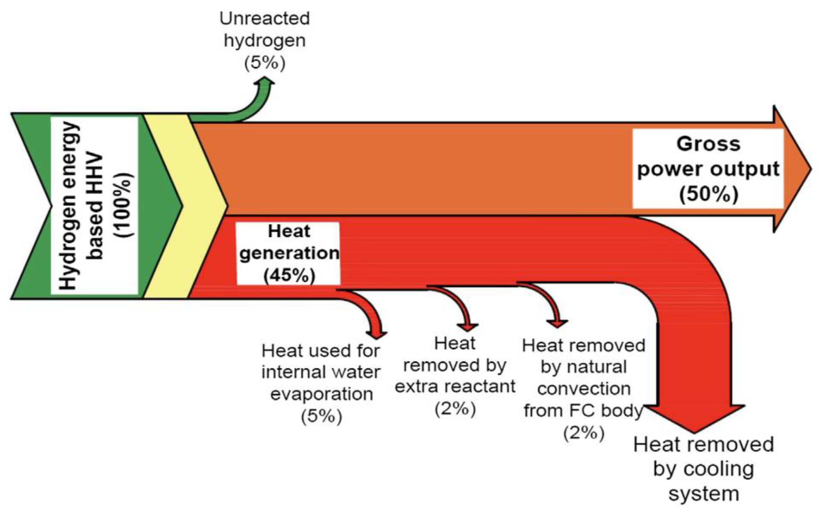
3.4. Thermal Management

Thermal management is crucial for PEMFCs’ safe and efficient operation. The optimal operating temperature for PEMFC is usually around 80 °C [162], and excessive heat generation can cause membrane drying, performance drop, and accelerated degradation, while low temperatures hinder reaction kinetics and risk flooding. Non-uniform temperature distribution impacts reactant, current density, and membrane water content, thereby affecting PEMFC performance and water management. In applications like multi-rotor drones, where space and heat dissipation are limited, effective thermal management is especially pivotal.
Common cooling methods for PEMFC include liquid cooling and air cooling, each with its specific applications and advantages and disadvantages. Liquid cooling systems are widely used in high-power PEMFC systems due to their high thermal conductivity efficiency and capacity. They remove the heat generated by the fuel cell stack through circulating coolant in the cooling channels. However, liquid cooling systems require additional pumps and pipelines, which increase system complexity and cost while potentially introducing leakage risks [162]. In contrast, air cooling systems have the advantages of simple structure and lightweight design without requiring additional pumps or pipelines; therefore, they are more suitable for compact and lightweight applications such as drones [163]. Air cooling systems remove heat from the fuel cell stack by increasing cathode airflow or designing independent cooling channels that utilize natural convection or forced convection of air. Setareh et al. [164] conducted a three-dimensional numerical thermal analysis to investigate the heat transfer and temperature distribution in an air-cooled PEMFC. Their findings revealed that the airflow rate significantly influenced the stack temperature, with increasing flow rates effectively reducing both maximum temperature and temperature gradient. Although air cooling has lower thermal conductivity efficiency compared to liquid cooling, it is sufficient for dissipating heat in low-power PEMFC systems like those used in drones, and significantly reduces system weight and complexity [165].
In addition to water cooling and air cooling technologies, the utilization of heat pipes for thermal dissipation has garnered significant scholarly attention. As two-phase heat transfer elements, heat pipes exhibit significant potential for thermal management of PEMFC stacks. Chang et al. [166] explored the application of heat pipe technology in thermal management of hydrogen PEMFCs for drones. The research results indicate that pulsating heat pipes can effectively improve the temperature consistency of PEMFCs, and variations in the external extension length of the heat pipe casing have minimal impact on fuel cell performance. However, due to their small size and limited heat dissipation power, integrating multiple heat pipes becomes necessary for high-power PEMFC stacks. This not only increases the volume and reduces power density, but also escalates system costs. Consequently, the utilization of heat pipes may not be suitable for weight-restricted devices like multi-rotor drones. To address these limitations, vapor chambers (VCs) are proposed as an alternative solution for PEMFC thermal management. VCs possess a large two-dimensional heat transfer plane and can better fulfill the requirements of efficient heat dissipation and temperature uniformity across PEMFCs with varying active areas.
Zhao et al. [167] integrated five vapor chambers as heat spreaders into a 10-cell air-cooled PEMFC stack, as shown in Figure 17, resulting in improved thermal management and performance. The PEMFC stack with vapor chambers showed higher output voltage and power compared to the stack without them, enabling an increase in current density of 33% and in output power of 10%. The vapor chambers facilitated heat transfer and temperature homogenization, with a maximum temperature difference of 5.3 °C between cells and a temperature gradient below 1.5 °C at a current density of 0.64 A/cm2.
To offer design insights for PEMFC stacks incorporating vapor chambers, Huang et al. [168,169] developed a lumped parameter model of an open-cathode PEMFC stack with a vapor chamber system, taking into account the cooling subsystem and variable configuration of vapor chambers. The findings demonstrated that the integration of vapor chambers enables air-cooled PEMFCs to operate at higher current densities, resulting in a 7.5 W increase in net power output. Additionally, each additional piece of vapor chamber reduces the operating temperature by approximately 0.9 °C while adding 82.7 g to the overall system weight.
After theoretical analysis, Bai et al. [170] designed and tested vapor chambers integrated into a PEMFC stack. Their experimental results showed that, during dynamic start-up from 0 A to 40 A, stacks with vapor chambers maintained lower temperatures compared to those without, remaining below 52.5 °C compared to 63.3 °C. During steady-state operation at 40 A, stacks with vapor chambers had a maximum temperature difference of less than 6 °C between cells and only 3.9 °C within a cell, highlighting the effectiveness of vapor chambers in maintaining reasonable operating temperatures and reducing temperature gradients.
Apart from the cooling method, the selection and optimization of bipolar plate materials are crucial for thermal management in air-cooled PEMFCs. Materials with high thermal conductivity, such as graphite and metal composites, can effectively transfer internal heat, improve heat dissipation efficiency, and reduce the formation of hotspots [171]. Yin et al. [172] developed two 3 kW air-cooled PEMFC stacks for multi-rotor drones, employing stamped metal sheets and machined graphite bipolar plates, respectively. The performances of these stacks were compared under various operating conditions. The results show that, with the same MEA component and active area, the metal BPP was significantly lighter than the graphite BPP by 40%, while the nominal power output of the metal PEMFC was 51.4 W, representing a 4% increase compared to the graphite PEMFC’s nominal power output of 49.5 W. As a result, the power density of the metal air-cooled PEMFC stack reached 1189 W/kg, which is beneficial for its application in drones. The temperature of the metal stack was noticeably lower than that of the graphite stack under nearly identical air supply conditions, with a temperature difference of approximately 5 °C for most load currents. This was due to the metal stack having superior heat dissipation capability compared to the graphite stack, which ultimately enhanced the performance of the stack.
Effective temperature control strategies can ensure the stable operation of a system under steady-state and dynamic load variations, improving the reaction efficiency and extending the lifespan of fuel cell systems [173]. Yuan et al. [174] examined thermal management for air-cooled PEMFCs using heat distribution optimization. A 3D numerical model was employed to analyze temperature distributions within the stack along the cooling channel direction. To reflect temperature gradients, a multi-node, control-oriented model was developed. The proposed thermal management system utilized finite-state machine control for coolant air flow direction and conventional PI control for air flow speed. Experimental results demonstrated that the presented temperature control scheme effectively reduced temperature gradients within 0.5 °C, thereby significantly enhancing stack performance.
Wang et al. [175] proposed a real-time power optimization strategy for air-cooled PEMFCs based on active temperature control. They designed an enhanced temperature perturb and observe (P&O) algorithm to obtain an optimal temperature reference in real time. Additionally, they employed a super-twisting algorithm (STA)-based controller to accurately track the target temperature under varying environmental conditions. The experimental results demonstrated a significant increase in output power of over 4% at relatively high loads, thereby validating the effectiveness of the proposed strategy for power optimization of air-cooled PEMFCs.
Yu et al. [176] proposed a thermal management approach for open-cathode PEMFCs based on constraint generalized predictive control (CGPC) and optimized strategies. A 1000 W stack model incorporating thermal dynamics was developed to design a temperature controller. The controller employed an enhanced CGPC strategy that integrated optimized rules relevant to practical applications. The experimental results demonstrated a significantly reduced average error of 0.032 °C compared to the PI control, while the proposed strategy outperformed the manufacturer’s default strategy by improving the stack performance by 28.9% and reducing the fan duty cycle. This approach exhibits significant potential for widespread application of PEMFCs.
To summarize, current thermal management strategies for PEMFCs focus on effective cooling techniques, temperature control strategies, and improving material properties to ensure safe and efficient operation. Among these, the inclusion of thermal systems and thorough consideration of the thermal properties in the design of fuel cell system structure are not only necessary, but crucial factors that determine the performance and durability of the system. This requires designers to carefully select appropriate cooling methods, as well as to meticulously plan the layout and connections of each component, to ensure effective heat transfer and dispersion.
When selecting cooling methods, options such as air cooling, liquid cooling, or heat pipe cooling can be adopted based on the system’s power and space limitations. For example, in space-constrained applications like drones, air cooling is preferred due to its simplicity and lack of additional cooling systems [165,172]. Notably, heat pipe technology has gained attention for its efficient phase-change mechanism, offering uniform temperature distribution and reduced system complexity [168,169,170]. Secondly, the thermal conductivity of the system is influenced by bipolar plates, which are vital components connecting fuel cells. The thermal performance of these plates directly impacts heat transfer. Using high thermal conductivity materials and optimizing their interface with gas diffusion layers (GDL) can significantly reduce thermal resistance, enhancing overall conduction efficiency. Moreover, the fiber structure and compression performance of GDL also affect thermal conductivity. Balancing the porosity and compression ratio is crucial for gas transport and heat conduction [163]. To address temperature gradients within the fuel cell stack, methods like multi-channel cooling structures, embedded heat pipes, or microchannel technology can be employed. For instance, simulations have shown that a serpentine channel design achieves better temperature uniformity than parallel channels [177]. The strategy of controlling the temperature gradient of fuel cell stack by optimizing air flow velocity and direction is discussed in Ref. [164].

3.5. The Influence of Gas Humidity on PEMFC Performance

The performance of PEMFC is significantly influenced by humidity, as evidenced by multiple studies. Maintaining appropriate humidity levels ensures full hydration of the proton exchange membrane, thereby promoting high ion conductivity and minimizing ohmic losses. Additionally, precise control of humidity can prevent flooding on the cathode side and membrane drying on the anode side, both of which can significantly reduce PEMFC performance. Hence, meticulous regulation of reaction gas humidity is imperative for enhancing the reliability and efficiency of PEMFC.
Due to the fact that the cathode of open-cathode air-cooled PEMFC commonly used in drones is exposed to the atmosphere, environmental humidity directly affects the performance of fuel cells. Therefore, it is important to study the effect of cathode humidity on PEMFC performance.
Sveshnikova et al. [178] designed a PEMFC stack with maximum power of 175 W to study the influence of inlet air temperature and relative humidity on the performance of the PEMFC. The results demonstrated that the efficiency of the PEMFC system exhibited an increase with higher relative humidity and lower inlet air temperature within the range of experimental parameters (inlet air temperature 15–25 °C, inlet air relative humidity 25–100%). The influence of air humidity on PEMFC efficiency was more pronounced than that of temperature, as evidenced by a 3.4% enhancement in PEMFC efficiency when increasing the relative humidity from 25% to 100%, as shown in Figure 18. The impact of humidity cycling on the performance and aging characteristics of MEA and single cells has been a subject of significant interest [179]. By subjecting PEMFC to high-humidity cycling tests (RHC 62%/100%) and comparing them with constant humidity conditions (RHC = 62%), it was observed that humidity cycling considerably accelerated MEA degradation. Specifically, under high-humidity cycling tests, PEMFC experienced an overall performance loss of 12 mV per hour, which was more pronounced than the 3 mV per hour loss under constant humidity conditions. These findings highlight substantial effects of humidity cycling conditions on PEMFC performance stability and MEA degradation.
Chen et al. [180] investigated the effects of hydrogen humidity on the performance of air-cooled PEMFCs. The results indicated that the performance of the PEMFC was improved with the increase in anode (hydrogen) relative humidity, which was due to the increase in H2O concentration in the cathode catalyst layer at high current density. For example, at an ambient temperature of 30 °C, when the anode relative humidity increased from 0 to 100%, the limiting current density increased by more than 40%. In addition, at high current density, the increase in anode relative humidity did not cause H2O flooding.
Many scholars have compared the impacts of anode and cathode gas humidity on the performance of PEMFC. Ozen et al. [181] tested cells with 25 cm2 active areas for different inlet gas humidity levels and found that the performance of the cells improved with an increase in the humidity of both cathode and anode gases, with a more significant effect observed for cathode gas humidity. As illustrated in the study, the power density of the PEMFC increased with higher humidity levels in the cathode gas under the same current density. Kim et al. [182] found through experiments that the variation in cathode humidity has a greater impact on the performance of PEMFCs than changes in anode humidity and stack temperature. When the cathode humidity is increased from 40% to 100%, there is a significant improvement in PEMFC performance, particularly reflected in the increase in average cell voltage. In contrast, changes in anode humidity have a smaller effect on PEMFC performance, but under dry anode conditions, there is a slight decrease in performance. Wang et al. [183], using orthogonal experiments and variance analysis, further analyzed the influence of cathode and anode gas humidities on PEMFC performance. The results showed that the air stoichiometry ratio had the greatest impact on PEMFC performance, followed by air humidity and operating temperature, while hydrogen humidity had the smallest influence. This further confirms the importance of cathode gas humidity for PEMFC performance. Based on these studies, it can be concluded that, during the optimization process of PEMFC performance, attention should be focused on controlling cathode gas humidity. By properly controlling cathode gas humidity, significant improvements can be achieved in PEMFCs’ performance characteristics, thereby enhancing their efficiency and stability for practical applications.
In order to better control the humidity of reaction gases in PEMFCs, Ou et al. [184] constructed a bubble humidifier and implemented real-time and efficient temperature and humidity management for PEMFCs using a multi-input multi-output (MIMO) fuzzy controller. Under simulation and experimental conditions, the optimization of humidity control exhibited a significant enhancement in the power output of PEMFC, resulting in an average increase of approximately 4.32%. This strategy effectively addressed the challenges of water-thermal management in PEMFCs, optimizing the hydration state of the membrane and enhancing system efficiency and stability. The application of this method in open-cathode PEMFC provides important support for improving its performance in applications such as multi-rotor drones.
In summary, the performance of PEMFCs is significantly influenced by the water content within the membrane. Therefore, ensuring an appropriate level of water content within the membrane to maintain proton conductivity and prevent dehydration is crucial for air humidification strategies. Common humidification methods include external approaches such as bubbling humidifiers; however, they have their own advantages as well as issues related to parasitic power consumption or equipment complexity. Self-humidification and internal humidification techniques rely on optimizing flow field plate design or improving stack design to achieve humidity control [185], which either depends on stack water production capacity or requires precise stack design and effective water management capabilities.
Currently, research on PEMFC humidification strategies has made significant progress, but still faces numerous challenges. Research directions primarily focus on enhancing humidity efficiency, exploring self-humidifying technology, and developing real-time control strategies to achieve optimal humidity effects. However, when applying a humidifier device to PEMFC drones, it is necessary to consider various challenges such as weight and volume limitations, energy management, environmental adaptability, and real-time stability. The key to achieving an optimal balance between performance and multiple factors lies in reducing device weight and volume while ensuring effective humidity control that minimizes energy consumption, improves environmental adaptability, and ensures real-time stability so that PEMFCs can operate reliably in drones.

3.6. Degradation of PEMFC System

The performance degradation of PEMFCs has long been a critical factor limiting their large-scale commercialization. This degradation process involves multiple aspects, including the catalyst layer, proton exchange membrane, gas diffusion layer (GDL), and the overall system design.
The catalyst layer, as the core region for electrochemical reactions in PEMFCs, directly affects the overall performance of the fuel cell. As Chu et al. [186] demonstrated through electrochemical impedance spectroscopy (EIS) analysis, the oxidation of platinum (Pt) catalysts is a major cause of stack performance degradation. The degradation of the catalyst layer is primarily attributed to the agglomeration and dissolution of Pt catalysts as well as the corrosion of carbon supports [187,188]. It has been found that the agglomeration and dissolution of Pt catalysts lead to a reduction in electrochemical active surface area (ECSA), which subsequently impacts the output performance of PEMFCs. Additionally, the corrosion of carbon supports contributes to the structural degradation and performance loss of the catalyst layer. By optimizing catalyst preparation methods, such as adding secondary or tertiary metals to form alloy catalysts, the stability and anti-agglomeration performance of the catalysts can be improved. Furthermore, the use of carbon supports with higher corrosion resistance, such as carbon nanotubes (CNTs) or graphene, can effectively mitigate the degradation of the catalyst layer [189].
In PEMFC systems, Nafion, as a key material for proton exchange membranes, significantly influences the overall performance of PEMFCs. Its performance degradation, manifested in reduced proton conductivity and weakened mechanical strength, is mainly caused by chemical, mechanical, and thermal degradation [190]. Chemical degradation is primarily attributed to the attack of hydrogen peroxide (H₂O₂) and radicals. Mechanical degradation arises primarily from stress changes due to the wet–dry cycling of the membrane. Owkonkwo et al. [191] suggested that enhancing the chemical structure of the membrane, such as by introducing cross-linkers to improve mechanical stability, and adopting composite membrane technology, such as by combining Nafion with inorganic nanoparticles, can enhance the chemical degradation resistance of the membrane. Additionally, optimizing PEMFC operating conditions, such as by controlling operating temperature and humidity, can effectively mitigate membrane degradation.
The gas diffusion layer (GDL), serving as a gas transport channel in PEMFCs, experiences performance degradation characterized by reduced hydrophobicity and clogged pore structures. This is primarily caused by the accumulation of contaminants on the GDL surface and the corrosion of carbon fibers [192]. By improving the preparation process of the GDL, such as by utilizing materials with higher hydrophobicity and applying coating techniques, the hydrophobic properties of the GDL can be enhanced. Simultaneously, optimizing water management strategies in PEMFCs to reduce the likelihood of liquid water covering the GDL surface can effectively mitigate GDL degradation.
Moreover, the overall system design of PEMFCs plays a crucial role in influencing their performance degradation [187]. Unreasonable system designs, such as improper flow field design and faulty sealing structures, can lead to uneven performance degradation and overall performance decline in PEMFCs.
Vichard et al. [193] proposed a method for predicting PEMFC performance degradation based on artificial intelligence technology, specifically utilizing the Echo State Network (ESN) model. Through data collected from long-term durability tests, the ESN model successfully simulated the performance evolution of PEMFCs under different operating conditions and predicted their performance degradation trends. This method maintained a low normalized root mean square error over a prediction period of over 2000 h, demonstrating high prediction accuracy. This research not only enhances the understanding of PEMFC performance degradation mechanisms, but also provides strong support for estimating the remaining useful life, planning maintenance operations, and optimizing energy management of PEMFCs, further promoting their commercialization process.
In summary, PEMFC performance degradation involves multiple aspects, but various mitigation measures can effectively slow down this process and enhance the feasibility of their commercial applications. The main types of PEMFC degradation and mitigation measures are summarized in Table 6.

3.7. Cold Start of PEMFC System

Due to the need for drones to operate in low-temperature and high-altitude environments, the cold start of PEMFCs, i.e., starting from a low-temperature state (especially below freezing point), poses a technical challenge. Here are several common methods for cold-starting PEMFCs:
(1)
External heating with air preheating
Preheating the air entering the PEMFC using an external heating device to raise the stack’s temperature is the first method. It has been mentioned in the literature that heating the air can quickly increase the temperature of the MEA (membrane electrode assembly), which is beneficial for initiating electrochemical reactions [194].
Coolant preheating: Preheating the coolant using an external heat source and raising the temperature of PEMFC stack through coolant circulation. This method provides fast heating but requires additional time to heat up the coolant before startup [195,196].
Heating end plates and insulation plates: In addition to preheating reactant gases and coolant, direct heating of end plates and insulation plates of PEMFC stack can also accelerate overall temperature increase [194].
(2)
Electrochemical reaction self-heating by increasing startup current
Rapidly increasing startup current to utilize large amount of heat generated by electrochemical reactions for quick elevation of stack’s temperature is the second method. This method requires precise control of current to prevent damage to cells [197].
Catalytic combustion-assisted heating: Introducing hydrogen gas and oxygen on cathode side for catalytic combustion reaction, utilizing combustion heat for rapid elevation of stack’s temperature. This method enables quick startup of PEMFC but requires additional hydrogen gas and an oxygen supply system.
(3)
Optimization control strategy [198]
Sequential control strategy: The strategy is adopted based on the thermal performance differences between various components in the PEMFC stack. Firstly, a staged heating control strategy is used to heat up components with smaller heat capacities, such as MEA, and then to gradually heat up components with larger heat capacities, such as end plates and coolant.
Adaptive current control: Real-time adjustment of operating current during cold start process to maximize heat generation and electrical energy output. This method can significantly improve cold start performance and prolong battery life.

4. Summary and Future Scope

With the advancement of technology, hydrogen fuel cell multi-rotor drones have gradually moved towards industrialization and modularization. Many fuel cell companies have developed their own series of multi-rotor drones; however, hydrogen fuel cell multi-rotor drones are still in the exploratory stage and have not yet been fully recognized by the market. Moreover, their issue of high cost has yet to be resolved. To further improve the performance of multi-rotor drones and expand their application range, in-depth research in basic science, engineering design, and top-level planning is still required. This paper summarizes some technical directions that fuel cell multi-rotor drone should focus on in the future:
  • Optimization of hydrogen storage methods.
Long flight time is the biggest advantage of hydrogen fuel cells as the power sources of multi-rotor drones. To further exploit this advantage, future research should focus on lightweight design, hydrogen storage methods, and energy management strategies. Among these, optimizing hydrogen storage methods is the technical route that can most significantly improve the drone’s flight time. Particularly, if efficient solid-state hydrogen storage can be achieved at a low cost, hydrogen fuel cell multi-rotor drones can truly achieve long-term and long-distance flight, and the drone industry will also usher in a revolutionary change.
2.
Cathode gas filtration system.
As the cathode of the open-cathode air-cooled fuel cell is directly connected to the atmosphere, if the working environment is heavily polluted, the pollutants in the air will directly damage the membrane electrode. This will result in a decrease in the life of the fuel cell, hindering the use of hydrogen fuel cell drones in polluted environments, such as coal mines and chemical plants. To expand the application scenarios of hydrogen fuel cell drones, further research on the cathode gas filtration system is needed.
3.
Auxiliary equipment.
To achieve the large-scale application of hydrogen fuel cell drones, in addition to the drone equipment itself, it is necessary to systematically plan and design a complete set of technologies for hydrogen storage, hydrogen transportation, and hydrogenation. Compared to hydrogen fuel cell vehicles, multi-rotor drones utilize very little hydrogen, so a portable mobile hydrogen refueling process can be designed for them to meet the frequent use.
The research and development of hydrogen fuel cell multi-rotor drones is a systematic project that integrates new energy, robotics, energy management, and many other technologies. Its development is closely related to the progress of basic disciplines such as materials, chemistry, and thermodynamics, indicating that if hydrogen fuel cell multi-rotor drones are properly applied in the future, their research and development will become increasingly subdivided and specialized, and top-level design will become increasingly significant.

Author Contributions

Conceptualization, S.L. and Z.S.; methodology, Z.S.; validation, S.L., Z.S. and W.Z.; formal analysis, Z.S. and W.Z.; investigation, Z.S., S.L. and D.R.; resources, Z.S. and D.R.; data curation, Q.X.; writing—original draft preparation, Z.S.; writing—review and editing, Z.S.; visualization, Z.S. and W.Z.; supervision, S.L.; project administration, S.L. and Y.F.; funding acquisition, Z.S. All authors have read and agreed to the published version of the manuscript.

Funding

This research was funded by China Coal Technology and Engineering Group Corp., grant number 2022-2-TD-QN002.

Conflicts of Interest

All authors were employed by China Coal Technology and Engineering Group Corp., the authors declare no conflicts of interest.

References

  1. Lee, C.; Kim, S.; Chu, B. A Survey: Flight Mechanism and Mechanical Structure of the UAV. Int. J. Precis. Eng. Manuf. 2021, 22, 719–743. [Google Scholar] [CrossRef]
  2. Hassanalian, M.; Abdelkefi, A. Classifications, applications, and design challenges of drones: A review. Prog. Aerosp. Sci. 2017, 91, 99–131. [Google Scholar] [CrossRef]
  3. Arat, H.T.; Sürer, M.G. Experimental investigation of fuel cell usage on an air Vehicle’s hybrid propulsion system. Int. J. Hydrogen Energy 2020, 45, 26370–26378. [Google Scholar] [CrossRef]
  4. Floreano, D.; Wood, R.J. Science, technology and the future of small autonomous drones. Nature 2015, 521, 460–466. [Google Scholar] [CrossRef]
  5. Mademlis, I.; Mygdalis, V.; Nikolaidis, N.; Montagnuolo, M.; Negro, F.; Messina, A.; Pitas, I. High-Level Multiple-UAV Cinematography Tools for Covering Outdoor Events. IEEE Trans. Broadcast. 2019, 65, 627–635. [Google Scholar] [CrossRef]
  6. Ahmed, F.; Mohanta, J.C.; Keshari, A.; Yadav, P.S. Recent Advances in Unmanned Aerial Vehicles: A Review. Arab. J. Sci. Eng. 2022, 47, 7963–7984. [Google Scholar] [CrossRef]
  7. Luo, H.; Zhang, P.; Wang, J.J.; Wang, G.Q.; Meng, F.H. Traffic Patrolling Routing Problem with Drones in an Urban Road System. Sensors 2019, 19, 5164. [Google Scholar] [CrossRef]
  8. Humpe, A. Bridge Inspection with an Off-the-Shelf 360 degrees Camera Drone. Drones 2020, 4, 67. [Google Scholar] [CrossRef]
  9. Velusamy, P.; Rajendran, S.; Mahendran, R.K.; Naseer, S.; Shafiq, M.; Choi, J.-G. Unmanned Aerial Vehicles (UAV) in Precision Agriculture: Applications and Challenges. Energies 2021, 15, 217. [Google Scholar] [CrossRef]
  10. Phang, S.K.; Chiang, T.H.A.; Happonen, A.; Chang, M.M.L. From Satellite to UAV-Based Remote Sensing: A Review on Precision Agriculture. IEEE Access 2023, 11, 127057–127076. [Google Scholar] [CrossRef]
  11. Chen, C.J.; Huang, Y.Y.; Li, Y.S.; Chen, Y.C.; Chang, C.Y.; Huang, Y.M. Identification of Fruit Tree Pests With Deep Learning on Embedded Drone to Achieve Accurate Pesticide Spraying. IEEE Access 2021, 9, 21986–21997. [Google Scholar] [CrossRef]
  12. Iost, F.H.; Heldens, W.B.; Kong, Z.D.; de Lange, E.S. Drones: Innovative Technology for Use in Precision Pest Management. J. Econ. Entomol. 2020, 113, 1–25. [Google Scholar] [CrossRef] [PubMed]
  13. Rejeb, A.; Abdollahi, A.; Rejeb, K.; Treiblmaier, H. Drones in agriculture: A review and bibliometric analysis. Comput. Electron. Agric. 2022, 198, 107017. [Google Scholar] [CrossRef]
  14. Hu, P.; Zhang, R.; Yang, J.; Chen, L. Development Status and Key Technologies of Plant Protection UAVs in China: A Review. Drones 2022, 6, 354. [Google Scholar] [CrossRef]
  15. Liu, Z.; Li, J. Application of Unmanned Aerial Vehicles in Precision Agriculture. Agriculture 2023, 13, 1375. [Google Scholar] [CrossRef]
  16. Yan, Y.H.; Lv, Z.Y.; Yuan, J.B.; Chai, J.G. ANALYSIS OF POWER SOURCE OF MULTIROTOR UAVs. Int. J. Robot. Autom. 2019, 34, 563–571. [Google Scholar] [CrossRef]
  17. Gong, A.; Verstraete, D. Fuel cell propulsion in small fixed-wing unmanned aerial vehicles: Current status and research needs. Int. J. Hydrogen Energy 2017, 42, 21311–21333. [Google Scholar] [CrossRef]
  18. Kesselman, S. The First 1,000 Commercial UAS Exemptions. 2014, pp. 1–22. Available online: https://higherlogicdownload.s3.amazonaws.com/AUVSI/b657da80-1a58-4f8f-9971-7877b707e5c8/UploadedFiles/ZAvlBnqWSeSYXPsnKkoc_Section333Report_online022516.pdf (accessed on 16 June 2024).
  19. Apeland, J.; Pavlou, D.G.; Hemmingsen, T. Sensitivity Study of Design Parameters for a Fuel Cell Powered Multirotor Drone. J. Intell. Robot. Syst. 2021, 102, 6. [Google Scholar] [CrossRef]
  20. Depcik, C.; Cassady, T.; Collicott, B.; Burugupally, S.P.; Li, X.; Alam, S.S.; Arandia, J.R.; Hobeck, J. Comparison of lithium ion Batteries, hydrogen fueled combustion Engines, and a hydrogen fuel cell in powering a small Unmanned Aerial Vehicle. Energy Convers. Manag. 2020, 207, 112514. [Google Scholar] [CrossRef]
  21. Pan, Z.F.; An, L.; Wen, C.Y. Recent advances in fuel cells based propulsion systems for unmanned aerial vehicles. Appl. Energy 2019, 240, 473–485. [Google Scholar] [CrossRef]
  22. Belmonte, N.; Staulo, S.; Fiorot, S.; Luetto, C.; Rizzi, P.; Baricco, M. Fuel cell powered octocopter for inspection of mobile cranes: Design, cost analysis and environmental impacts. Appl. Energy 2018, 215, 556–565. [Google Scholar] [CrossRef]
  23. Cai, Q.; Brett, D.J.L.; Browning, D.; Brandon, N.P. A sizing-design methodology for hybrid fuel cell power systems and its application to an unmanned underwater vehicle. J. Power Sources 2010, 195, 6559–6569. [Google Scholar] [CrossRef]
  24. Savvaris, A.; Xie, Y.; Malandrakis, K.; Lopez, M.; Tsourdos, A. Development of a fuel cell hybrid-powered unmanned aerial vehicle. In Proceedings of the 24th Mediterranean Conference on Control and Automation (MED), Athens, Greece, 24 June 2016. [Google Scholar]
  25. Samimi, F.; Rahimpour, M.R. Direct Methanol Fuel Cell. In Methanol; Elsevier: Amsterdam, The Netherlands, 2018; pp. 381–397. [Google Scholar]
  26. Guangul, F.M.; Chala, G.T. A Comparative Study between the Seven Types of Fuel Cells. Appl. Sci. Eng. Prog. 2020, 13, 185–194. [Google Scholar] [CrossRef]
  27. Sazali, N.; Wan Salleh, W.N.; Jamaludin, A.S.; Mhd Razali, M.N. New Perspectives on Fuel Cell Technology: A Brief Review. Membranes 2020, 10, 99. [Google Scholar] [CrossRef]
  28. Sharaf, O.Z.; Orhan, M.F. An overview of fuel cell technology: Fundamentals and applications. Renew. Sustain. Energy Rev. 2014, 32, 810–853. [Google Scholar] [CrossRef]
  29. Tang, A.; Crisci, L.; Bonville, L.; Jankovic, J. An overview of bipolar plates in proton exchange membrane fuel cells. J. Renew. Sustain. Energy 2021, 13, 022701. [Google Scholar] [CrossRef]
  30. Liu, C.Y.; Sung, C.C. A review of the performance and analysis of proton exchange membrane fuel cell membrane electrode assemblies. J. Power Sources 2012, 220, 348–353. [Google Scholar] [CrossRef]
  31. Zhang, G.; Kandlikar, S.G. A critical review of cooling techniques in proton exchange membrane fuel cell stacks. Int. J. Hydrogen Energy 2012, 37, 2412–2429. [Google Scholar] [CrossRef]
  32. Ramezanizadeh, M.; Nazari, M.A.; Ahmadi, M.H.; Chen, L.E. A review on the approaches applied for cooling fuel cells. Int. J. Heat Mass Transf. 2019, 139, 517–525. [Google Scholar] [CrossRef]
  33. Graf, C.; Friedrich, K.A.; Vath, A.; Nicoloso, N. Dynamic load and temperature behavior of a PEFC-hybrid-system. J. Fuel Cell Sci. Technol. 2006, 3, 403–409. [Google Scholar] [CrossRef]
  34. Fluckiger, R.; Tiefenauer, A.; Ruge, M.; Aebi, C.; Wokaun, A.; Buchi, F.N. Thermal analysis and optimization of a portable, edge-air-cooled PEFC stack. J. Power Sources 2007, 172, 324–333. [Google Scholar] [CrossRef]
  35. Zakhvatkin, L.; Schechter, A.; Buri, E.; Avrahami, I. Edge Cooling of a Fuel Cell during Aerial Missions by Ambient Air. Micromachines 2021, 12, 1432. [Google Scholar] [CrossRef]
  36. Kurnia, J.C.; Chaedir, B.A.; Sasmito, A.P.; Shamim, T. Progress on open cathode proton exchange membrane fuel cell: Performance, designs, challenges and future directions. Appl. Energy 2021, 283, 116359. [Google Scholar] [CrossRef]
  37. Nguyen, H.Q.; Shabani, B. Proton exchange membrane fuel cells heat recovery opportunities for combined heating/cooling and power applications. Energy Convers. Manag. 2020, 204, 112328. [Google Scholar] [CrossRef]
  38. EnergyOr shows off world’s first fuel cell multirotor UAV. Fuel Cells Bull. 2015, 2015, 5–6. [CrossRef]
  39. EnergyOr fuel cell multirotor drone in 2 h flight with camera. Fuel Cells Bull. 2016, 2016, 3–4. [CrossRef]
  40. Horizon launches Hycopter fuel cell multirotor UAV. Fuel Cells Bull. 2015, 2015, 4. [CrossRef]
  41. Liu, L.; Cao, X.; Zhang, X.; He, Y. Review of development of light and small scale solar/hydrogen powered unmanned aerial vehicles. Acta Aeronaut. Astronaut. Sin. 2019, 41, 623474. [Google Scholar]
  42. Dutczak, J. Compressed hydrogen storage in contemporary fuel cell propulsion systems of small drones. IOP Conf. Ser. Mater. Sci. Eng. 2018, 421, 042013. [Google Scholar] [CrossRef]
  43. Chinese UAV maker MMC flies hydrogen fuel cell drone for 4 h. Fuel Cells Bull. 2016, 2016, 4–5. [CrossRef]
  44. Antunes, J. Fly Farther and Longer with FlightWave’s Hydrogen-Powered Jupiter-H2 Drone. Available online: https://www.commercialuavnews.com/infrastructure/fly-farther-longer-flightwaves-hydrogen-powered-jupiter-h2-drone (accessed on 25 April 2023).
  45. Intelligent Energy fuel cells for new ISS UAV. Fuel Cells Bull. 2020, 2020, 6. [CrossRef]
  46. Loughborough. Intelligent Energy’s 2.4 kW Fuel Cell Power Module Integrated into Latest UAV Product from ISS Aerospace. Available online: https://www.intelligent-energy.com/news/intelligent-energys-2-4kw-fuel-cell-power-module-integrated-into-latest-uav-product-from-iss-aerospace/ (accessed on 17 March 2023).
  47. HES multirotor drone, designed and built in US, has 3h flight time. Fuel Cells Bull. 2018, 2018, 5. [CrossRef]
  48. Skycorp hydrogen fuel cell powered drone with advanced AI. Fuel Cells Bull. 2018, 2018, 5. [CrossRef]
  49. Intelligent Energy powers two multirotor UAVs to new records. Fuel Cells Bull. 2019, 2019, 5–6. [CrossRef]
  50. Nordic Unmanned in hydrogen drone flight. Fuel Cells Bull. 2021, 2021, 5–6. [CrossRef]
  51. FuelCellWorks. MetaVista Breaks Guinness World Record of Multi Rotor UAV Flight Time Using Intelligent Energy Fuel Cell Power Module. Available online: https://fuelcellsworks.com/news/metavista-breaks-guinness-world-record-of-multi-rotor-uav-flight-time-using-intelligent-energy-fuel-cell-power-module/ (accessed on 16 March 2023).
  52. Intelligent Energy links up with UAV maker, unveils new module. Fuel Cells Bull. 2017, 2017, 4. [CrossRef]
  53. Intelligent Energy unveils 800 W fuel cell for commercial UAVs. Fuel Cells Bull. 2018, 2018, 6. [CrossRef]
  54. Intelligent Energy launches 2.4 kW fuel cell module for UAVs. Fuel Cells Bull. 2019, 2019, 6. [CrossRef]
  55. FuelCellsWorks. Unlocking the Potential of Hydrogen for Increased Drone Capabilities: Intelligent Energy Launches New Product to Provide Higher Power Up to1.6 kW for UAVs. Available online: https://fuelcellsworks.com/news/unlocking-the-potential-of-hydrogen-for-increased-drone-capabilities-intelligent-energy-launches-new-product-to-provide-higher-power-up-to-1-6kw-for-uavs/ (accessed on 16 June 2024).
  56. Intelligent Energy module provides up to 1.6 kW for UAVs. Fuel Cells Bull. 2019, 2019, 5. [CrossRef]
  57. Intelligent Energy fuel cells power endurance drone for US Army. Fuel Cells Bull. 2020, 2020, 5–6. [CrossRef]
  58. Doosan sets foot in UAV fuel cell market. Fuel Cells Bull. 2018, 2018, 6. [CrossRef]
  59. Doosan Mobility Innovation demos fuel cell drone for Africa. Fuel Cells Bull. 2020, 2020, 6. [CrossRef]
  60. DMI launches modular hydrogen fuel cell power pack for drones. Fuel Cells Bull. 2020, 2020, 6. [CrossRef]
  61. Chia, A.F.Y.; Min, K.M. Design and Performance Analysis of a Fuel Cell Powered Heavy-Lift Multirotor Drone. In Proceedings of the 2021 the Asia-Pacific International Symposium on Aerospace Technology (APISAT 2021), Jeju, Republic of Korea, 15–17 November 2021; Lecture Notes in Electrical Engineering. Springer: Cham, Switzerland, 2023; Volume 1, pp. 269–282. [Google Scholar]
  62. DMI fuel cell drone delivers face masks to remote Korean islands. Fuel Cells Bull. 2020, 2020, 5–6. [CrossRef]
  63. Ballard turnkey fuel cell solutions to power commercial UAVs. Fuel Cells Bull. 2019, 2019, 6. [CrossRef]
  64. FuelCellWorks. China: World Record Flight Time for Hydrogen Fuel Cell Drone. Available online: https://fuelcellsworks.com/news/china-world-record-flight-time-for-hydrogen-fuel-cell-drone/ (accessed on 24 March 2023).
  65. GB/T 38954-2020; Hydrogen Fuel Cell Power System for Unmanned Aerial Vehicles. Chinese Standard: Beijing, China, 2020.
  66. Boukoberine, M.N.; Zia, M.F.; Benbouzid, M.; Zhou, Z.; Donateo, T. Hybrid fuel cell powered drones energy management strategy improvement and hydrogen saving using real flight test data. Energy Convers. Manag. 2021, 236, 113987. [Google Scholar] [CrossRef]
  67. Coxworth, B. Hydrogen-Powered Hycopter Quadcopter Could Fly for 4 Hours at a Time. Available online: https://newatlas.com/horizon-energy-systems-hycopter-fuel-cell-drone/37585/ (accessed on 28 April 2024).
  68. Phoenix. Available online: https://www.spectronik.com/drone (accessed on 10 May 2024).
  69. Ball, M. UAV Fuel Cells Tested in Cold-Weather Conditions. Available online: https://www.unmannedsystemstechnology.com/2019/12/uav-fuel-cells-tested-in-cold-weather-conditions/ (accessed on 28 April 2024).
  70. A Drone System Optimized around Achieving the Best Fuel Cell Powerpack Performance DS30W. Available online: https://www.doosanmobility.com/en/products/drone-ds30 (accessed on 10 May 2024).
  71. Apeland, J.; Pavlou, D.; Hemmingsen, T. Suitability Analysis of Implementing a Fuel Cell on a Multirotor Drone. J. Aerosp. Technol. Manag. 2020, 12, e3220. [Google Scholar] [CrossRef]
  72. HydroCopter 4. Available online: https://www.hydrogencraft.com/en/Uploads/file/20240107/d93aadd7d5eaade8e6b483f5df78585c.pdf (accessed on 10 May 2024).
  73. A Durable, Versatile Commercial Drone Solution DT30X. Available online: https://www.doosanmobility.com/en/products/drone-dt30 (accessed on 10 May 2024).
  74. Mohsan, S.A.H.; Othman, N.Q.H.; Li, Y.; Alsharif, M.H.; Khan, M.A. Unmanned aerial vehicles (UAVs): Practical aspects, applications, open challenges, security issues, and future trends. Intell. Serv. Robot. 2023, 16, 109–137. [Google Scholar] [CrossRef] [PubMed]
  75. Tsuchiya, H. Mass production cost of PEM fuel cell by learning curve. Int. J. Hydrogen Energy 2004, 29, 985–990. [Google Scholar] [CrossRef]
  76. Porstmann, S.; Wannemacher, T.; Drossel, W.G. A comprehensive comparison of state-of-the-art manufacturing methods for fuel cell bipolar plates including anticipated future industry trends. J. Manuf. Process. 2020, 60, 366–383. [Google Scholar] [CrossRef]
  77. Kim, K.H.; Lim, J.W.; Kim, M.; Dai, G.L. Development of carbon fabric/graphite hybrid bipolar plate for PEMFC. Compos. Struct. 2013, 98, 103–110. [Google Scholar] [CrossRef]
  78. Hermann, A.; Chaudhuri, T.; Spagnol, P. Bipolar plates for PEM fuel cells: A review. Int. J. Hydrogen Energy 2005, 30, 1297–1302. [Google Scholar] [CrossRef]
  79. Marchetti, G.A. Thin Graphite Bipolar Plate with Associated Gaskets and Carbon Cloth Flow-Field for Use in an Ionomer Membrane Fuel Cell. U.S. Patent 6,503,654, 7 January 2003. [Google Scholar]
  80. Emanuelson, C.R.; Taylor, A.W.; Luoma, L.W. Separator Plate For Electrochemical Cells. Patent CA1164934A, 3 April 1984. [Google Scholar]
  81. Fan, R.; Peng, Y.; Tian, H.; Zheng, J.; Zhang, C.J.A.P.-C.S. Graphite-Filled Composite Bipolar Plates for Fuel Cells: Material, Structure, and Performance. Acta Phys. Chim. Sin. 2020, 37, 2009095. [Google Scholar] [CrossRef]
  82. Kuan, H.C.; Ma, C.C.M.; Chen, K.H.; Chen, S.M. Preparation, electrical, mechanical and thermal properties of composite bipolar plate for a fuel cell. J. Power Sources 2004, 134, 7–17. [Google Scholar] [CrossRef]
  83. Muller, A.; Kauranen, P.; von Ganski, A.; Hell, B. Injection moulding of graphite composite bipolar plates. J. Power Sources 2006, 154, 467–471. [Google Scholar] [CrossRef]
  84. Jo, J.; Zhang, X.; Ansari, A. Lightweight Pem Fuel Cell Stack for Unmanned Aerial Vehicle. In Proceedings of the ASME Heat Transfer Conference, Online, 7–11 June 2021. [Google Scholar]
  85. Song, Y.; Zhang, C.; Ling, C.-Y.; Han, M.; Yong, R.-Y.; Sun, D.; Chen, J. Review on current research of materials, fabrication and application for bipolar plate in proton exchange membrane fuel cell. Int. J. Hydrogen Energy 2020, 45, 29832–29847. [Google Scholar] [CrossRef]
  86. Tawfik, H.; Hung, Y.; Mahajan, D. Metal bipolar plates for PEM fuel cell—A review. J. Power Sources 2007, 163, 755–767. [Google Scholar] [CrossRef]
  87. Hung, Y.; El-Khatib, K.M.; Tawfik, H. Corrosion-resistant lightweight metallic bipolar plates for PEM fuel cells. J. Appl. Electrochem. 2005, 35, 445–447. [Google Scholar] [CrossRef]
  88. DMI, POSCO SPS aim to cut weight of fuel cell drones. Fuel Cells Bull. 2021, 2021, 6. [CrossRef]
  89. Wang, H.L.; Sweikart, M.A.; Turner, J.A. Stainless steel as bipolar plate material for polymer electrolyte membrane fuel cells. J. Power Sources 2003, 115, 243–251. [Google Scholar] [CrossRef]
  90. Lin, C.H.; Tsai, S.Y. An investigation of coated aluminium bipolar plates for PEMFC. Appl. Energy 2012, 100, 87–92. [Google Scholar] [CrossRef]
  91. Yan, P.F.; Ying, T.; Yang, Y.; Cao, F.Y.; Li, Y.X.; Wang, J.Y.; Zeng, X.Q. Investigation of anodized Ta/Ag coating on magnesium bipolar plate for lightweight proton exchange membrane fuel cells. Corros. Sci. 2022, 197, 110086. [Google Scholar] [CrossRef]
  92. Xu, Z.; Qiu, D.; Yi, P.; Peng, L.; Lai, X.J. Towards mass applications: A review on the challenges and developments in metallic bipolar plates for PEMFC—ScienceDirect. Prog. Nat. Sci. Mater. Int. 2020, 30, 815–824. [Google Scholar] [CrossRef]
  93. Dobrovol’skii, Y.A.; Ukshe, A.E.; Levchenko, A.V.; Arkhangel’skii, I.V.; Ionov, S.G.; Avdeev, V.V.; Aldoshin, S.M. Materials for bipolar plates for proton-conducting membrane fuel cells. Russ. J. Gen. Chem. 2007, 77, 752–765. [Google Scholar] [CrossRef]
  94. Aukland, N.; Boudina, A.; Eddy, D.S.; Mantese, J.V.; Thompson, M.P.; Wang, S.S. Alloys that form conductive and passivating oxides for proton exchange membrane fuel cell bipolar plates. J. Mater. Res. 2004, 19, 1723–1729. [Google Scholar] [CrossRef]
  95. Gou, Y.; Jiang, G.; Geng, J.T.; Shao, Z.G. Properties of NbC/a-C:H films on titanium bipolar plates for proton exchange membrane fuel cells. Fuel Cells 2022, 23, 51–59. [Google Scholar] [CrossRef]
  96. Li, T.; Zhang, H.Y.; Wang, Y.; Wu, C.L.; Yan, Y.G.; Chen, Y.G. TiCr transition layer promoting the growth of high-stability TiCrN coating for titanium bipolar plate. Surf. Coat. Technol. 2022, 451, 129026. [Google Scholar] [CrossRef]
  97. Wang, Z.D.; Zhang, B.; Gao, K.X.; Liu, R.X. Adjustable TiN coatings deposited with HiPIMS on titanium bipolar plates for PEMFC. Int. J. Hydrogen Energy 2022, 47, 39215–39224. [Google Scholar] [CrossRef]
  98. Yin, Q.; Zhang, K.; Fu, X.Z.; Wang, X.Z.; Luo, J.L. Rapid coating preparation strategy for chromium nitride coated titanium bipolar plates of proton exchange membrane fuel cells. Int. J. Hydrogen Energy 2022, 47, 31435–31445. [Google Scholar] [CrossRef]
  99. Zhang, H.B.; Hou, M.; Lin, G.Q.; Han, Z.Y.; Fu, Y.; Sun, S.C.; Shao, Z.G.; Yi, B.L. Performance of Ti-Ag-deposited titanium bipolar plates in simulated unitized regenerative fuel cell (URFC) environment. Int. J. Hydrogen Energy 2011, 36, 5695–5701. [Google Scholar] [CrossRef]
  100. Wu, S.; Yang, W.; Yan, H.; Zuo, X.; Cao, Z.; Li, H.; Shi, M.; Chen, H. A review of modified metal bipolar plates for proton exchange membrane fuel cells. Int. J. Hydrogen Energy 2021, 46, 8672–8701. [Google Scholar] [CrossRef]
  101. Gao, P.; Xie, Z.; Ouyng, C.; Wu, X.; Lei, T.; Liu, C.; Huang, Q. Carbon composite coatings on Ti for corrosion protection as bipolar plates of proton exchange membrane fuel cells. Micro Nano Lett. 2018, 13, 931–935. [Google Scholar] [CrossRef]
  102. Zhang, F.; Zhao, P.C.; Niu, M.; Maddy, J. The survey of key technologies in hydrogen energy storage. Int. J. Hydrogen Energy 2016, 41, 14535–14552. [Google Scholar] [CrossRef]
  103. Li, M.X.; Bai, Y.F.; Zhang, C.Z.; Song, Y.X.; Jiang, S.F.; Grouset, D.; Zhang, M.J. Review on the research of hydrogen storage system fast refueling in fuel cell vehicle. Int. J. Hydrogen Energy 2019, 44, 10677–10693. [Google Scholar] [CrossRef]
  104. Barthélémy, H. Hydrogen storage—Industrial prospectives. Int. J. Hydrogen Energy 2012, 37, 17364–17372. [Google Scholar] [CrossRef]
  105. Zheng, J.; Liu, X.; Xu, P.; Liu, P.; Zhao, Y.; Yang, J. Development of high pressure gaseous hydrogen storage technologies. Int. J. Hydrogen Energy 2012, 37, 1048–1057. [Google Scholar] [CrossRef]
  106. Rohit, G.; Santosh, M.S.; Kumar, M.N.; Raghavendra, K. Numerical investigation on structural stability and explicit performance of high-pressure hydrogen storage cylinders. Int. J. Hydrogen Energy 2023, 48, 5565–5575. [Google Scholar] [CrossRef]
  107. Cho, S.M.; Kim, C.; Kim, K.S.; Kim, D.K. Lightweight hydrogen storage cylinder for fuel cell propulsion systems to be applied in drones. Int. J. Press. Vessel. Pip. 2021, 194, 104428. [Google Scholar] [CrossRef]
  108. Cho, S.M.; Kim, K.S.; Kim, W.; Choi, S.J. Application of PET as a non-metallic liner for the 6.8 L type-4 cylinder based on the hydrogen cycling test. Int. J. Hydrogen Energy 2022, 47, 6965–6973. [Google Scholar] [CrossRef]
  109. Roh, H.S.; Hua, T.Q.; Ahluwalia, R.K. Optimization of carbon fiber usage in Type 4 hydrogen storage tanks for fuel cell automobiles. Int. J. Hydrogen Energy 2013, 38, 12795–12802. [Google Scholar] [CrossRef]
  110. Alcántar, V.; Aceves, S.M.; Ledesma, E.; Ledesma, S.; Aguilera, E. Optimization of Type 4 composite pressure vessels using genetic algorithms and simulated annealing. Int. J. Hydrogen Energy 2017, 42, 15770–15781. [Google Scholar] [CrossRef]
  111. Lee, Y.; Park, E.T.; Jeong, J.; Shi, H.; Kim, J.; Kang, B.S.; Song, W. Weight optimization of hydrogen storage vessels for quadcopter UAV using genetic algorithm. Int. J. Hydrogen Energy 2020, 45, 33939–33947. [Google Scholar] [CrossRef]
  112. Guo, L.; Su, J.; Wang, Z.; Shi, J.; Guan, X.; Cao, W.; Ou, Z. Hydrogen safety: An obstacle that must be overcome on the road towards future hydrogen economy. Int. J. Hydrogen Energy 2024, 51, 1055–1078. [Google Scholar] [CrossRef]
  113. Zhang, Y.; Wang, S.; Cui, B.; Zhang, N. Analysis of Crash Characteristics of Hydrogen Storage Structure of Hydrogen Powered UAV. Aerospace 2022, 9, 687. [Google Scholar] [CrossRef]
  114. Ma, Q.; He, Y.; You, J.; Chen, J.; Zhang, Z. Probabilistic risk assessment of fire and explosion of onboard high-pressure hydrogen system. Int. J. Hydrogen Energy 2024, 50, 1261–1273. [Google Scholar] [CrossRef]
  115. Zhang, Z.; Yu, F.; Qu, D. Analysis of millisecond collision of composite high pressure hydrogen storage cylinder. Int. J. Hydrogen Energy 2023, 48, 11578–11591. [Google Scholar] [CrossRef]
  116. Chen, L.; Xu, K.; Yang, Z.; Yan, Z.; Dong, Z. Optimal Design and Operation of Dual-Ejector PEMFC Hydrogen Supply and Circulation System. Energies 2022, 15, 5427. [Google Scholar] [CrossRef]
  117. Chen, J.X.; Veenstra, M.; Purewal, J.; Hobein, B.; Papasauva, S. Modeling a hydrogen pressure regulator in a fuel cell system with Joule-Thomson effect. Int. J. Hydrogen Energy 2019, 44, 1272–1287. [Google Scholar] [CrossRef]
  118. The LW351 Series Operating and Service Manual. Available online: https://www.pressure-tech.com/files/124/LW-351%20Series%20-%20O&S%20Manual.pdf (accessed on 16 June 2024).
  119. Zhang, Y.H.; Jia, Z.C.; Yuan, Z.M.; Yang, T.; Qi, Y.; Zhao, D.L. Development and Application of Hydrogen Storage. J. Iron Steel Res. Int. 2015, 22, 757–770. [Google Scholar] [CrossRef]
  120. Chen, Y.Z.; Zhao, S.L.; Ma, H.J.; Wang, H.; Hua, L.; Fu, S. Analysis of Hydrogen Embrittlement on Aluminum Alloys for Vehicle-Mounted Hydrogen Storage Tanks: A Review. Metals 2021, 11, 1303. [Google Scholar] [CrossRef]
  121. Niste, V.B.; Tanaka, H.; Ratoi, M.; Sugimura, J. WS2 nanoadditized lubricant for applications affected by hydrogen embrittlement. RSC Adv. 2015, 5, 40678–40687. [Google Scholar] [CrossRef]
  122. Tarhan, C.; Çil, M.A. A study on hydrogen, the clean energy of the future: Hydrogen storage methods. J. Energy Storage 2021, 40, 102676. [Google Scholar] [CrossRef]
  123. Moradi, R.; Groth, K.M. Hydrogen storage and delivery: Review of the state of the art technologies and risk and reliability analysis. Int. J. Hydrogen Energy 2019, 44, 12254–12269. [Google Scholar] [CrossRef]
  124. Stroman, R.O.; Schuette, M.W.; Swider-Lyons, K.; Rodgers, J.A.; Edwards, D.J. Liquid hydrogen fuel system design and demonstration in a small long endurance air vehicle. Int. J. Hydrogen Energy 2014, 39, 11279–11290. [Google Scholar] [CrossRef]
  125. Aziz, M. Liquid Hydrogen: A Review on Liquefaction, Storage, Transportation, and Safety. Energies 2021, 14, 5917. [Google Scholar] [CrossRef]
  126. Kang, D.; Yun, S.; Kim, B.-k. Review of the Liquid Hydrogen Storage Tank and Insulation System for the High-Power Locomotive. Energies 2022, 15, 4357. [Google Scholar] [CrossRef]
  127. Yatsenko, E.A.; Goltsman, B.M.; Novikov, Y.V.; Izvarin, A.I.; Platov, I.V.R. Review on modern ways of insulation of reservoirs for liquid hydrogen storage. Int. J. Hydrogen Energy 2022, 47, 41046–41054. [Google Scholar] [CrossRef]
  128. Osborn, W.; Markmaitree, T.; Shaw, L.L.; Ren, R.M.; Hu, J.Z.; Kwak, J.H.; Yang, Z.G. Solid-State Hydrogen Storage: Storage Capacity, Thermodynamics, and Kinetics. JOM 2009, 61, 45–51. [Google Scholar] [CrossRef]
  129. Khafidz, N.Z.A.; Yaakob, Z.; Lim, K.L.; Timmiati, S.N. The kinetics of lightweight solid-state hydrogen storage materials: A review. Int. J. Hydrogen Energy 2016, 41, 13131–13151. [Google Scholar] [CrossRef]
  130. Rimza, T.; Saha, S.; Dhand, C.; Dwivedi, N.; Patel, S.S.; Singh, S.; Kumar, P. Carbon-Based Sorbents for Hydrogen Storage: Challenges and Sustainability at Operating Conditions for Renewable Energy. Chemsuschem 2022, 15, e202200281. [Google Scholar] [CrossRef]
  131. Manilov, A.I.; Skryshevsky, V.A. Hydrogen in porous silicon—A review. Mater. Sci. Eng. B-Adv. Funct. Solid-State Mater. 2013, 178, 942–955. [Google Scholar] [CrossRef]
  132. Muduli, R.C.; Kale, P. Silicon nanostructures for solid-state hydrogen storage: A review. Int. J. Hydrogen Energy 2023, 48, 1401–1439. [Google Scholar] [CrossRef]
  133. Thomas, K.M. Adsorption and desorption of hydrogen on metal–organic framework materials for storage applications: Comparison with other nanoporous materials. Dalton Trans. 2009, 1487–1505. [Google Scholar] [CrossRef]
  134. Samantaray, S.S.; Putnam, S.T.; Stadie, N.P. Volumetrics of Hydrogen Storage by Physical Adsorption. Inorganics 2021, 9, 45. [Google Scholar] [CrossRef]
  135. Pedicini, R.; Sacca, A.; Carbone, A.; Passalacqua, E. Hydrogen storage based on polymeric material. Int. J. Hydrogen Energy 2011, 36, 9062–9068. [Google Scholar] [CrossRef]
  136. First UAV test flight with Cella solid-state hydrogen storage. Fuel Cells Bull. 2016, 3, 4–5.
  137. Kim, H.; Oh, T.H.; Kwon, S. Simple catalyst bed sizing of a NaBH4 hydrogen generator with fast startup for small unmanned aerial vehicles. Int. J. Hydrogen Energy 2016, 41, 1018–1026. [Google Scholar] [CrossRef]
  138. Kwon, S.M.; Kim, M.J.; Kang, S.; Kim, T. Development of a high-storage-density hydrogen generator using solid-state NaBH4 as a hydrogen source for unmanned aerial vehicles. Appl. Energy 2019, 251, 113331. [Google Scholar] [CrossRef]
  139. Salman, M.S.; Rambhujun, N.; Pratthana, C.; Lai, Q.; Aguey-Zinsou, K.F. Solid-state hydrogen storage as a future renewable energy technology. In Nano Tools and Devices for Enhanced Renewable Energy; Elsevier: Amsterdam, The Netherlands, 2021. [Google Scholar]
  140. O’Hayre, R.; Cha, S.-W.; Colella, W.G.; Prinz, F.B. Fuel Cell Fundamentals; John Wiley & Sons: Hoboken, NJ, USA, 2009. [Google Scholar]
  141. Wang, H.; Lin, H.J.; Cai, W.T.; Ouyang, L.Z.; Zhu, M. Tuning kinetics and thermodynamics of hydrogen storage in light metal element based systems—A review of recent progress. J. Alloys Compd. 2016, 658, 280–300. [Google Scholar] [CrossRef]
  142. Chen, Z.; Ma, Z.; Zheng, J.; Li, X.; Akiba, E.; Li, H.-W. Perspectives and challenges of hydrogen storage in solid-state hydrides. Chin. J. Chem. Eng. 2021, 29, 1–12. [Google Scholar] [CrossRef]
  143. Lang, C.; Jia, Y.; Yao, X. Recent advances in liquid-phase chemical hydrogen storage. Energy Storage Mater. 2020, 26, 290–312. [Google Scholar] [CrossRef]
  144. Yanxing, Z.; Maoqiong, G.; Yuan, Z.; Xueqiang, D.; Jun, S. Thermodynamics analysis of hydrogen storage based on compressed gaseous hydrogen, liquid hydrogen and cryo-compressed hydrogen. Int. J. Hydrogen Energy 2019, 44, 16833–16840. [Google Scholar] [CrossRef]
  145. Rivard, E.; Trudeau, M.; Zaghib, K. Hydrogen Storage for Mobility: A Review. Materials 2019, 12, 1973. [Google Scholar] [CrossRef] [PubMed]
  146. Ozbek, E.; Yalin, G.; Ekici, S.; Karakoc, T.H. Evaluation of design methodology, limitations, and iterations of a hydrogen fuelled hybrid fuel cell mini UAV. Energy 2020, 213, 118757. [Google Scholar] [CrossRef]
  147. Erdinc, O.; Uzunoglu, M. Recent trends in PEM fuel cell-powered hybrid systems: Investigation of application areas, design architectures and energy management approaches. Renew. Sustain. Energy Rev. 2010, 14, 2874–2884. [Google Scholar] [CrossRef]
  148. Vural, B.; Dusmez, S.; Uzunoglu, M.; Ugur, E.; Akin, B. Fuel Consumption Comparison of Different Battery/Ultracapacitor Hybridization Topologies for Fuel-Cell Vehicles on a Test Bench. IEEE J. Emerg. Sel. Top. Power Electron. 2014, 2, 552–561. [Google Scholar] [CrossRef]
  149. Ustolin, F.; Taccani, R. Fuel cells for airborne usage: Energy storage comparison. Int. J. Hydrogen Energy 2018, 43, 11853–11861. [Google Scholar] [CrossRef]
  150. Ahmadi, S.; Bathaee, S.M.T.; Hosseinpour, A.H. Improving fuel economy and performance of a fuel-cell hybrid electric vehicle (fuel-cell, battery, and ultra-capacitor) using optimized energy management strategy. Energy Convers. Manag. 2018, 160, 74–84. [Google Scholar] [CrossRef]
  151. Karunarathne, L.; Economou, J.T.; Knowles, K. Power and energy management system for fuel cell unmanned aerial vehicle. Proc. Inst. Mech. Eng. Part G-J. Aerosp. Eng. 2012, 226, 437–454. [Google Scholar] [CrossRef]
  152. Gang, B.G.; Kwon, S. Design of an energy management technique for high endurance unmanned aerial vehicles powered by fuel and solar cell systems. Int. J. Hydrogen Energy 2018, 43, 9787–9796. [Google Scholar] [CrossRef]
  153. Xu, L.; Huangfu, Y.; Ma, R.; Xie, R.; Song, Z.; Zhao, D.; Yang, Y.; Wang, Y.; Xu, L. A Comprehensive Review on Fuel Cell UAV Key Technologies: Propulsion System, Management Strategy, and Design Procedure. IEEE Trans. Transp. Electrif. 2022, 8, 4118–4139. [Google Scholar] [CrossRef]
  154. Apeland, J.; Pavlou, D.; Hemmingsen, T. State-of-Technology and Barriers for Adoption of Fuel Cell Powered Multirotor Drones. In Proceedings of the International Conference on Unmanned Aircraft Systems (ICUAS), Athens, Greece, 1–4 September 2020; pp. 1359–1367. [Google Scholar]
  155. Zhang, X.; Liu, L.; Dai, Y.; Lu, T. Experimental investigation on the online fuzzy energy management of hybrid fuel cell/battery power system for UAVs. Int. J. Hydrogen Energy 2018, 43, 10094–10103. [Google Scholar] [CrossRef]
  156. Lei, T.; Min, Z.; Fu, H.; Zhang, X.; Li, W.; Zhang, X. Dynamic balanced energy management strategies for fuel-cell hybrid power system of unmanned air vehicle. Acta Aeronaut. Astronaut. Sin. 2020, 41, 15. [Google Scholar]
  157. Boukoberine, M.N.; Donateo, T.; Benbouzid, M. Optimized Energy Management Strategy for Hybrid Fuel Cell Powered Drones in Persistent Missions using Real Flight Test Data. IEEE Trans. Energy Convers. 2022, 37, 2080–2091. [Google Scholar] [CrossRef]
  158. Liu, H.; Yao, Y.; Wang, J.; Qin, Y.; Li, T.J. A control architecture to coordinate energy management with trajectory tracking control for fuel cell/battery hybrid unmanned aerial vehicles. Int. J. Hydrogen Energy 2022, 47, 15236–15253. [Google Scholar] [CrossRef]
  159. Yao, Y.; Wang, J.; Zhou, Z.; Li, H.; Liu, H.; Li, T. Grey Markov prediction-based hierarchical model predictive control energy management for fuel cell/battery hybrid unmanned aerial vehicles. Energy 2023, 262, 125405. [Google Scholar] [CrossRef]
  160. Yan, Y.; Wang, B.; Wang, C.; Zhao, D.; Xiao, C. Adaptive maximum power point tracking based on Kalman filter for hydrogen fuel cell in hybrid unmanned aerial vehicle applications. Int. J. Hydrogen Energy 2023, 48, 25939–25957. [Google Scholar] [CrossRef]
  161. Zeng, D.; Guo, X.; Guo, K.; Dong, Z.; Yu, X. Design and Management of a Hydrogen Fuel Cell Powered Quadrotor. In Proceedings of the 2023 International Conference on Unmanned Aircraft Systems (ICUAS), Warsaw, Poland, 6–9 June 2023; pp. 644–651. [Google Scholar]
  162. Chen, Q.; Zhang, G.; Zhang, X.; Sun, C.; Jiao, K.; Wang, Y. Thermal management of polymer electrolyte membrane fuel cells: A review of cooling methods, material properties, and durability. Appl. Energy 2021, 286, 116496. [Google Scholar] [CrossRef]
  163. Afshari, E.; Asghari, S.; Jahantigh, N.; Shamsizadeh, P. Recent advancements and prospects of thermal management strategies in polymer electrolyte membrane (PEM) fuel cells. In Handbook of Thermal Management Systems; Elsevier: Amsterdam, The Netherlands, 2023; pp. 417–440. [Google Scholar]
  164. Shahsavari, S.; Desouza, A.; Bahrami, M.; Kjeang, E. Thermal analysis of air-cooled PEM fuel cells. Int. J. Hydrogen Energy 2012, 37, 18261–18271. [Google Scholar] [CrossRef]
  165. Meng, H.; Yu, X.; Luo, X.; Tu, Z. Modelling and operation characteristics of air-cooled PEMFC with metallic bipolar plate used in unmanned aerial vehicle. Energy 2024, 300, 131559. [Google Scholar] [CrossRef]
  166. Chang, Z.; Fan, Y.; Jiang, W.; Zhang, J.; Zhang, J. Simulation Research on Thermal Management of Hydrogen Fuel Cell for UAV. In 6GN for Future Wireless Networks; Lecture Notes of the Institute for Computer Sciences, Social Informatics and Telecommunications Engineering; Springer: Cham, Switzerland, 2024; pp. 390–408. [Google Scholar]
  167. Zhao, J.; Huang, Z.; Jian, B.; Bai, X.; Jian, Q. Thermal performance enhancement of air-cooled proton exchange membrane fuel cells by vapor chambers. Energy Convers. Manag. 2020, 213, 112830. [Google Scholar] [CrossRef]
  168. Huang, Z.; Jian, Q. Cooling efficiency optimization on air-cooling PEMFC stack with thin vapor chambers. Appl. Therm. Eng. 2022, 217, 119238. [Google Scholar] [CrossRef]
  169. Huang, Z.; Jian, Q.; Zhao, J. Thermal management of open-cathode proton exchange membrane fuel cell stack with thin vapor chambers. J. Power Sources 2021, 485, 229314. [Google Scholar] [CrossRef]
  170. Bai, X.; Jian, Q. Experimental study of a passive thermal management system using vapor chamber for proton exchange membrane fuel cell stack. Renew. Energy 2023, 216, 119095. [Google Scholar] [CrossRef]
  171. Li, Q.; Liu, Z.; Sun, Y.; Yang, S.; Deng, C. A Review on Temperature Control of Proton Exchange Membrane Fuel Cells. Processes 2021, 9, 235. [Google Scholar] [CrossRef]
  172. Yin, C.; Hua, S.; Nie, W.; Yang, H.; Tang, H. Comparative study on air-cooled fuel cell stacks with metal and graphite bipolar plate designs for unmanned aerial vehicles. eTransportation 2024, 21, 100344. [Google Scholar] [CrossRef]
  173. He, L.; Yang, Y.; Zhang, Y.; Li, P.; Xin, Y. A review of thermal management of proton exchange membrane fuel cell systems. J. Renew. Sustain. Energy 2023, 15, 012703. [Google Scholar] [CrossRef]
  174. Yuan, W.-W.; Ou, K.; Kim, Y.-B. Thermal management for an air coolant system of a proton exchange membrane fuel cell using heat distribution optimization. Appl. Therm. Eng. 2020, 167, 114715. [Google Scholar] [CrossRef]
  175. Wang, Y.-X.; Chen, Q.; Zhang, J.; He, H. Real-time power optimization for an air-coolant proton exchange membrane fuel cell based on active temperature control. Energy 2021, 220, 119497. [Google Scholar] [CrossRef]
  176. Yu, X.; Zhang, C.; Li, M.; Wang, G.; Tu, Z.; Yu, T.; Dong, H.; Zhao, F. Thermal management of an open-cathode PEMFC based on constraint generalized predictive control and optimized strategy. Renew. Energy 2024, 220, 119608. [Google Scholar] [CrossRef]
  177. Yin, C.; Gao, Y.; Li, K.; Wu, D.; Song, Y.; Tang, H. Design and numerical analysis of air-cooled proton exchange membrane fuel cell stack for performance optimization. Energy Convers. Manag. 2021, 245, 114604. [Google Scholar] [CrossRef]
  178. Sveshnikova, A.; Abrosimov, K.; Khayrullina, A.; Ustinov, A. Effect of ambient air conditions on PEM fuel cell performance. J. Renew. Sustain. Energy 2017, 9, 044301. [Google Scholar] [CrossRef]
  179. Huang, B.T.; Chatillon, Y.; Bonnet, C.; Lapicque, F.; Leclerc, S.; Hinaje, M.; Raël, S. Experimental Investigation of Air Relative Humidity (RH) Cycling Tests on MEA/Cell Aging in PEMFC Part I: Study of High RH Cycling Test With air RH at 62%/100%. Fuel Cells 2012, 12, 335–346. [Google Scholar] [CrossRef]
  180. Chen, Z.; Ingham, D.; Ismail, M.; Ma, L.; Hughes, K.J.; Pourkashanian, M. Effects of hydrogen relative humidity on the performance of an air-breathing PEM fuel cell. Int. J. Numer. Methods Heat Fluid Flow 2019, 30, 2077–2097. [Google Scholar] [CrossRef]
  181. Ozen, D.N.; Timurkutluk, B.; Altinisik, K. Effects of operation temperature and reactant gas humidity levels on performance of PEM fuel cells. Renew. Sustain. Energy Rev. 2016, 59, 1298–1306. [Google Scholar] [CrossRef]
  182. Kim, S.; Hong, I. Effects of humidity and temperature on a proton exchange membrane fuel cell (PEMFC) stack. J. Ind. Eng. Chem. 2008, 14, 357–364. [Google Scholar] [CrossRef]
  183. Wang, B.; Lin, R.; Liu, D.; Xu, J.; Feng, B. Investigation of the effect of humidity at both electrode on the performance of PEMFC using orthogonal test method. Int. J. Hydrogen Energy 2019, 44, 13737–13743. [Google Scholar] [CrossRef]
  184. Ou, K.; Yuan, W.-W.; Choi, M.; Yang, S.; Kim, Y.-B. Performance increase for an open-cathode PEM fuel cell with humidity and temperature control. Int. J. Hydrogen Energy 2017, 42, 29852–29862. [Google Scholar] [CrossRef]
  185. Nefedkin, S.I.; Klimova, M.A.; Glasov, V.S.; Pavlov, V.I.; Tolmachev, Y.V. Effect of the corrugated bipolar plate design on the self-humidification of a high power density PEMFC stack for UAVs. Fuel Cells 2021, 21, 234–253. [Google Scholar] [CrossRef]
  186. Chu, T.; Wang, Q.; Xie, M.; Wang, B.; Yang, D.; Li, B.; Ming, P.; Zhang, C. Investigation of the reversible performance degradation mechanism of the PEMFC stack during long-term durability test. Energy 2022, 258, 124747. [Google Scholar] [CrossRef]
  187. Li, B.; Wan, K.; Xie, M.; Chu, T.; Wang, X.; Li, X.; Yang, D.; Ming, P.; Zhang, C. Durability degradation mechanism and consistency analysis for proton exchange membrane fuel cell stack. Appl. Energy 2022, 314, 119020. [Google Scholar] [CrossRef]
  188. Fan, L.; Zhao, J.; Luo, X.; Tu, Z. Comparison of the performance and degradation mechanism of PEMFC with Pt/C and Pt black catalyst. Int. J. Hydrogen Energy 2022, 47, 5418–5428. [Google Scholar] [CrossRef]
  189. Wei, X.; Wang, R.-Z.; Zhao, W.; Chen, G.; Chai, M.-R.; Zhang, L.; Zhang, J. Recent research progress in PEM fuel cell electrocatalyst degradation and mitigation strategies. EnergyChem 2021, 3, 100061. [Google Scholar] [CrossRef]
  190. Patil, V.; Reshmi, P.V.; Prajna, S.; Yashaswi; Yashaswini; Haleshappa, D.; Jayarama, A.; Pinto, R. Degradation mechanisms in PEM fuel cells: A brief review. Mater. Today Proc. 2023. [Google Scholar] [CrossRef]
  191. Okonkwo, P.C.; Ben Belgacem, I.; Emori, W.; Uzoma, P.C. Nafion degradation mechanisms in proton exchange membrane fuel cell (PEMFC) system: A review. Int. J. Hydrogen Energy 2021, 46, 27956–27973. [Google Scholar] [CrossRef]
  192. Luo, L.; Huang, B.; Cheng, Z.; Jian, Q. Rapid degradation characteristics of an air-cooled PEMFC stack. Int. J. Energy Res. 2020, 44, 4784–4799. [Google Scholar] [CrossRef]
  193. Vichard, L.; Harel, F.; Ravey, A.; Venet, P.; Hissel, D. Degradation prediction of PEM fuel cell based on artificial intelligence. Int. J. Hydrogen Energy 2020, 45, 14953–14963. [Google Scholar] [CrossRef]
  194. Zhan, Z.; Yuan, C.; Hu, Z.; Wang, H.; Sui, P.C.; Djilali, N.; Pan, M. Experimental study on different preheating methods for the cold-start of PEMFC stacks. Energy 2018, 162, 1029–1040. [Google Scholar] [CrossRef]
  195. Wan, Z.; Chang, H.; Shu, S.; Wang, Y.; Tang, H. A Review on Cold Start of Proton Exchange Membrane Fuel Cells. Energies 2014, 7, 3179–3203. [Google Scholar] [CrossRef]
  196. Wei, L.; Dafalla, A.M.; Jiang, F. Effects of reactants/coolant non-uniform inflow on the cold start performance of PEMFC stack. Int. J. Hydrogen Energy 2020, 45, 13469–13482. [Google Scholar] [CrossRef]
  197. Lei, L.; He, P.; He, P.; Tao, W.-Q. Numerical Research on the Cold Start-up Strategy of a PEMFC Stack from −30 °C. J. Therm. Sci. 2022, 32, 898–910. [Google Scholar] [CrossRef]
  198. Pan, W.; Li, P.; Gan, Q.; Chen, X.; Wang, F.; Dai, G. Thermal stability analysis of cold start processes in PEM fuel cells. Appl. Energy 2020, 261, 114430. [Google Scholar] [CrossRef]
Figure 1. Ragone plot describing the energy density vs. power density of various energy storage technologies [23].
Energies 17 04193 g001
Figure 2. Proton exchange membrane fuel cells (PEMFC) single-cell structure.
Energies 17 04193 g002
Figure 3. A typical energy flow diagram in a PEMFC [37].
Energies 17 04193 g003
Figure 4. Typical configuration of an open-cathode PEMFC power system.
Energies 17 04193 g004
Figure 5. Early hydrogen fuel cell multi-rotor drones: (a) H2Quad from EnergyOr; (b) fuel cell drone from Intelligent Energy; (c) Ranger from Zhongyu Power; (d) HYDrone-1800 from MMC.
Energies 17 04193 g005
Figure 6. Hydrogen fuel cell multi-rotor drones for inspection: (a) Hycopter from HES; (b) Sensus4 from ISS Aerospace; (c) Sensus6 from ISS Aerospace; (d) Staaker BG-200 from Nordic Unmanned.
Energies 17 04193 g006
Figure 7. The liquid hydrogen storage fuel cell drone from Meta Vista [51].
Energies 17 04193 g007
Figure 8. IE-Soar 650 W fuel cell module and the fuel cell drone developed based on IE-Soar 650 W module.
Energies 17 04193 g008
Figure 9. DP30 fuel cell pack and DS30 drone from Doosan Mobility Innovation.
Energies 17 04193 g009
Figure 10. Fuel cell drone from Ballard [63].
Energies 17 04193 g010
Figure 11. Global sales and production distribution of fuel cell drones in 2022 by region.
Energies 17 04193 g011
Figure 12. Power density and hydrogen consumption vs. current density [87].
Energies 17 04193 g012
Figure 13. Structure of different types of gas cylinders.
Energies 17 04193 g013
Figure 14. Hybrid power supply system topology [66].
Energies 17 04193 g014
Figure 15. Overview of the energy management strategies of fuel cell drones [153].
Energies 17 04193 g015
Figure 16. Comparison of the hydrogen consumption of drones based on the energy management strategies [155].
Energies 17 04193 g016
Figure 17. Heat transfer paths in the PEMFC stack with vapor chambers [167].
Energies 17 04193 g017
Figure 18. Effect of inlet air temperature and relative humidity on FC efficiency [178].
Energies 17 04193 g018
Table 1. Comparison of various fuel cells [25,26,27].
DMFCPEMFCSOFC
Operating temperature/°C<120<120800–1000
Released power<5 kW5–250 kW100–250 kW
Type of electrolyteNafion membraneNafion membraneYttria stabilized zirconia
Anode reactionCH3OH + H2O → CO2 + 6H+ + 6eH2 → 2H+ + 2eH2 + O2− → H2O + 2e
Cathode reaction3/2O2 + 6H+ + 6e → 3H2O1/2O2 + 2H+ + 2e → H2O1/2O2 + 2e → O2−
AdvantagesEasy fuel storage, simple structure without thermal managementHigh power density, fast startupDiversified fuel, non-noble
metal for catalyst
DisadvantagesLow power densityLow energy density of storing hydrogen at high pressure or in metal hydrideSlow startup and complex auxiliary equipments due to high operating temperature
Table 2. Hydrogen fuel cell multi-rotor drones.
NameManufacturerYearFC System PowerNumber of RotorsH2 Storage MethodFlight TimeWeight of the DroneRefs.
H2Quad-400EnergyOr
(Montreal, QC, Canada)
2015400 W4Compressed gaseous133 min9.5 kg[38]
——Intelligent Energy
(Loughborough, UK)
2015650 W4Compressed gaseous85 min4.3 kg (with a 2 L cylinder)[66]
HycopterHES
(Singapore)
2015——4Compressed gaseous180 min5 kg[40,67]
RangerZhongyu
(Wuhan, China)
20151200 W6Compressed gaseous210 min12.7 kg[41]
HYDrone-1800MMC
(Shenzhen, China)
20161800 W6Compressed gaseous270 min20 kg[42,43]
Jupiter-H2FlightWave
(Santa Monica, CA, USA)
2016650 W8Compressed gaseous≥120 min——[44]
Sensus4ISS Aerospace
(Berkshire, UK)
2018800 W4Compressed gaseous90 [email protected] kg, 30 min@6 kg——[45]
e-Drone ZeroSkycorp
(Tartu, Estonia )
2018800 W4Compressed gaseous120 min——[48]
Sensus6ISS Aerospace
(Berkshire, UK)
20192400 W6Compressed gaseous120 min@8 kg, 25 min@20 kg——[46]
PhoenixSpectronik
(Singapore)
20192000 W6Compressed gaseous90 min19.0 kg (with a 9 L cylinder)[68]
BFD H2-6Ballard
(Burnaby, BC, Canada)
20191200 W6Compressed gaseous90 min——[69]
——Meta Vista
(Seoul, South Korea)
2019800 W4Liquid≥720 min——[51]
DS30DMI
(Gyeonggi-do, South Korea)
20192700 W8Compressed gaseous120 min 21.9 kg (with a 10.8 L cylinder)[70]
BG-200Nordic Unmanned
(Sandnes, Norway)
20202000 W8Compressed gaseous99 min20.7 kg (with a 7.2 L cylinder)[50,71]
——Xinyan Chuangneng
(Beijing, China)
20202000 W6Compressed gaseous331 min(with a 19 L cylinder)[64]
Hydrocopter-04Hydrogen Craft
(Huzhou, China)
20203400 W6Compressed gaseous180 min, 150 min@lkg, 96 min@5 kg20 kg (with a 12 L cylinder)[72]
DT30XDMI
(Gyeonggi-do, South Korea)
20232700 W6Compressed gaseous150 min21 kg (with 10.8 L Type 4 cylinder)[73]
‘——’ indicates that the drone does not have an official name.
Table 3. Technical parameters of the different types of high-pressure hydrogen cylinders [103].
Cylinder TypesMaterialsHydrogen Storage Pressure (MPa)Mass Percent (%)Volumetric Hydrogen Storage Density (g/L)Service Life (a)
Type IAll metal17.5–20≈114.28–17.2815
Type IIMetal liner with hoop wrapping26.3–30≈1.514.28–17.2815
Type IIIMetal liner with full composite wrapping30–702.4–4.135–4015–20
Type IVPlastic liner with full composite wrapping>702.5–5.738–4015–20
The unit ‘a’ in the service life of a gas cylinder refers to “years” (the first letter of annual). This unit is used to indicate the number of consecutive years a gas cylinder has been in use.
Table 4. Comparison of various direct H2 storage systems [140].
Storage SystemMass Storage Efficiency
(%kg H2/kg storage)
Volumetric Storage Density
(kg H2/L storage)
Gravimetric Storage Energy Density
(kWh/kg)
Volumetric Storage Energy Density
(kWh/L)
Compressed H2, 300 bars3.10.0141.20.55
Compressed H2, 700 bars4.80.0331.91.30
Cryogenic Liquid H214.20.0435.571.68
Cryo-compression tank (LLNL)7.380.0452.461.51
Metal hydride (conservative)0.650.0280.261.12
Note: The mass and volume of the entire storage system (tank, valves, tubing, and regulators) are taken into account in these data.
Table 5. Missions suitable for different EMSs.
StrategiesSuitable MissionsMission Risk
Rule-based EMSSuitable for scenarios characterized by relatively stable mission requirements and infrequent load fluctuations, such as fixed-route cruising and stationary monitoring.The mission risk is relatively low. These strategies are easy to implement and require less computational power, but they may not be able to cope with sudden high power demands or extreme load fluctuations.
Optimization-based EMSSuitable for scenarios that require efficient energy utilization and complex missions, such as long-duration multi-stage missions, reconnaissance, and surveillance in complex urban environments.The mission risk is moderately high. These strategies can optimize energy allocation and improve overall efficiency, but they have a higher computational complexity, requiring certain system performance and real-time requirements, as well as being sensitive to initial conditions and parameter settings.
Intelligent-based EMSSuitable for highly dynamic and uncertain missions, such as independent exploration and search and rescue in complex terrain environments.The missions carry high risks. These strategies possess strong adaptability and learning capabilities, enabling them to cope with complex environmental changes and mission requirements. However, they require a large amount of training data and computational resources, and may suffer from overfitting and poor generalization abilities.
Table 6. Main types of PEMFC degradation.
Degradation TypesDegradation MechanismsMitigation Measures
Proton exchange membrane degradation
(a)
Chemical degradation: Hydrogen peroxide attacks the free radicals, while metal ions act as catalysts to accelerate degradation.
(b)
Mechanical degradation: Accumulated stress leads to fatigue and damage, resulting in detachment of the membrane from the catalyst layer.
(c)
Thermal degradation: Hydrolsis or pyrolysis reactions at elevated temperatures disrupt the membrane structure.
(d)
Impurity contamination: Metal ions and organic deposits impede proton conduction.
(e)
Flooding and drying out: Inadequate water management leads to performance decline.
(a)
Chemical degradation: optimize fuel cell design, use antioxidants, control metal ion content.
(b)
Mechanical degradation: improve preparation process, optimize operating conditions, use toughening film materials.
(c)
Thermal degradation: control operating temperature, use high-thermal-stability film materials.
(d)
Impurity contamination: increase fuel and air purity, clean regularly, add filtration treatment.
(e)
Water flooding and drying up: optimize water management strategy, use membrane materials with good water retention performance, consider the comprehensive effects of humidity and temperature.
Catalyst layer degradation
(a)
Aggregation and migration of catalyst: Platinum catalyst nanoparticles may aggregate due to Ostwald ripening during operation, leading to a decrease in active surface area and affecting catalytic performance. At the same time, the migration of the catalyst in MEA can result in a loss of active sites.
(b)
Carbon support corrosion: In acidic environments, carbon supports may undergo electrochemical corrosion, weakening their bond with the catalyst and causing detachment of catalyst particles, thereby reducing catalytic activity.
(c)
Degradation of ionomer: Free radicals such as hydrogen peroxide can attack ionomers (such as Nafion), leading to their degradation and subsequently affecting proton conductivity and performance of the catalytic layer.
(a)
Aggregation and migration of catalyst: Optimizing catalyst structure: Prepare smaller and more stable catalyst nanoparticles to minimize the likelihood of aggregation.
(b)
Carbon support corrosion: Utilize more durable materials: Choose corrosion-resistant carbon carriers and ion polymer materials to enhance overall stability.
(c)
Degradation of ionomer: Enhance water management: Reduce the generation of free radicals, such as hydrogen peroxide, by optimizing the water management system while safeguarding ion polymers.
Gas diffusion layer (GDL) dagradation
(a)
Loss of hydrophobicity: As the fuel cell operates, the hydrophobic properties of GDL gradually diminish, resulting in a decline in its water management capabilities and impacting the effective diffusion and drainage performance of reaction gases.
(b)
Impurity adhesion: Dust particles and other contaminants present in the environment adhere to the surface of GDL, obstructing gas channels and increasing resistance to gas transport.
(c)
Chemical corrosion: Under specific operating conditions, GDL undergoes chemical reactions with substances within the fuel cell, leading to material corrosion.
Overall system design
(a)
Design of bipolar plates: Unreasonable dimensions and shapes of the flow channels in bipolar plates can result in uneven distribution of reaction gases, affecting fuel cell performance.
(b)
Sealing and assembly: aging and failure of sealing materials can lead to gas leakage, reducing fuel cell efficiency. The stress generated during the assembly process may cause damage to electrode structures, accelerating degradation.
(a)
Design of bipolar plates: Develop a well-designed flow channel structure to ensure the uniform distribution of reaction gas.
(b)
Sealing and assembly: Choose high-quality sealing materials and conduct aging tests to validate their effectiveness. Streamline assembly procedures, minimize assembly stress, and guarantee the integrity of electrode structures.
Disclaimer/Publisher’s Note: The statements, opinions and data contained in all publications are solely those of the individual author(s) and contributor(s) and not of MDPI and/or the editor(s). MDPI and/or the editor(s) disclaim responsibility for any injury to people or property resulting from any ideas, methods, instructions or products referred to in the content.

