Abstract
In Korea, the demand for complete underground installation of power distribution equipment installed on roads and green areas is increasing. In addition, KEPCO is making efforts to build a more reliable system for the underground distribution system. To meet these needs, this paper proposes the S-substation. In the S-substation, an RMU, a large power transformer, and an LV-Board (including ATCB and MCCB) are installed within the underground structure. This paper proposes three models to apply the S-substation to the underground distribution system. Power flow analysis is conducted for each model by simulating a variety of loads and DERs, and the frequency fluctuations are also examined under different distribution system events. An economic analysis is also conducted to select the optimal model. The economic analysis focuses on VOLL and construction costs. Based on power flow and economic analysis, one model is selected, and the underground distribution system that the model is applied is presented.
1. Introduction
This paper analyzes the optimal Low Voltage (LV) distribution system for introducing the Secondary Substation (S-substation) in underground distribution systems. The S-substation has been implemented in the underground distribution system in Korea for the following reasons:
- The need for complete undergrounding of Power Distribution Equipment (PDE) for underground Distribution Lines (D/Ls) supply.
- A desire to improve the aesthetics of PDE installed on sidewalks.
- The introduction of a highly reliable underground distribution system.
- The expansion of the LV supply range.
To meet these requirements, the S-substation installs a larger and more reliable PDE than the existing PDE for supplying underground D/Ls. The Ring Main Unit (RMU) is installed in place of the pad-mounted switchgear, and the oil-filled transformer replaces the pad-mounted transformer. Transformers in S-substations can be installed with capacities ranging from 1 to 2 MVA, which is larger than conventional transformers. This paper concentrates on the LV distribution system rather than the High Voltage (HV) distribution system. In the S-substation, the LV-board (including Automatic Transfer Circuit Breaker (ATCB) and Mold Case Circuit Breaker (MCCB)) is installed to reduce the fault duration time in the LV distribution system and to prevent cascading failures. Additionally, all PDE are waterproof so that the structures can operate under flood conditions [1].
Unlike the HV distribution system, the LV distribution system operates as a radial system, and in the event of a fault on the transformer, all connected loads experience a power outage. In contrast, during a power outage in the HV distribution systems, only a short power outage is experienced due to switching HV D/Ls. However, in case of a transformer fault, the recovery time is prolonged, so the customers experience a long power outage.
Only now has the LV distribution system received less attention than the HV distribution system. The HV distribution system is equipped with an automated system known as the Distribution Automation System (DAS), and continuous efforts are made to reduce fault duration and sections through protection coordination analysis. In contrast, the LV distribution system lacks such automation and coordination efforts. In particular, the underground LV distribution system should be of greater interest due to the following characteristics.
- The capacity of transformers in underground systems is typically larger than those in overhead distribution systems.
- Three-phase cables are installed under the assumption of three-phase loads.
- The fuses within the transformer protect the entire LV distribution system.
- Fault sections are challenging to locate due to the underground installation.
Therefore, this paper focuses more on the LV distribution system than on the HV distribution system, as installing the S-substation requires modifications to the existing LV distribution system model.
This paper also introduces the concept of the S-substation and presents a case study of its installation by KEPCO. The current underground distribution system is introduced, and three types of LV distribution system models suitable for S-secondary are presented. Power Flow (PF) and economic analysis are conducted to compare each model. The “Result & Discuss” section presents the example model and considerations when the model selected as the optimal LV model is currently applied to the underground distribution system.
The main keywords in this paper are power flow, the LV distribution system, and secondary substation. Previous studies on these topics include a paper on PF in distribution systems, which primarily analyzed the influence of the Distributed Energy Resources (DERs) connection. The algorithm for PF focuses on the economic dispatch of energy and ancillary services based on market prices at the system level. Simulation results show the effectiveness of the approach [2]. The main aim of the second paper is to enhance solar performance distribution and increase photovoltaic (PV), providing an overview of unbalanced optimal power flow [3]. The third paper provides a comprehensive understanding of the optimal power flow problem and proposes potential solutions. This paper proposes a comprehensive overview of prospective advancements and compares the diverse methodologies employed in optimal power flow [4].
Few studies specifically examine the LV distribution system. One paper examined the control of electric currents from renewable energy sources (RESs) in Microgrid systems [5], while another analyzed algorithms that control voltage and reactive power in LV distribution networks [6].
Finally, one of the studies on S-substations includes that S-substations devote autonomous management of the connected LV network and provide grid flexibility services [7]. With the digitalization of these nodes, S-substation allows the development of innovative solutions for predictive maintenance and life extension of the assets [8]. Other studies primarily focused on testing the electrical characteristics of its structure or internal PDE (such as dielectric tests, internal arc tests, and temperature rise tests) [9,10,11]. However, previous studies have not examined the optimal LV distribution system model for applying S-substations.
2. Secondary Substation
2.1. S-Substation
The distribution station improves the aesthetics of the city by collecting and installing many PDEs installed on the ground in one space. In addition, RMUs, large power transformers, and LV boards are installed to enable more reliable operation of the distribution systems. However, applying distribution stations (inside large Buildings) in all areas is challenging due to difficulties in securing and maintaining buildings. In particular, securing a building or a place where LV loads range from 500 to 2000 kW can be difficult; otherwise, using S-substations is increasingly attracting attention as a solution in such cases. This method involves installing and supplying PDE in underground structures without requiring the construction or purchase of a separate building. Figure 1 shows the circuit diagram of the station and Figure 2 depicts actual pictures of the S-substation installed in Korea.

Figure 1.
S-substation concept figure.

Figure 2.
S-substation in Korea.
2.2. Underground Distribution Systems
For LV distribution systems, both overhead and underground D/Ls are supplied as radial systems. On overhead D/Ls, single-phase transformers ranging from 10 to 150 kVA are used, while for underground D/Ls, three-phase transformers ranging from 150 to 500 kVA are currently used. Large power transformers are also expected to be used in the future (Currently, individual load is limited to less than 1000 kW). A figure of the current underground distribution system is shown below [12].
In this figure, solid lines indicate HV D/Ls, whereas dotted lines represent LV D/Ls. The switchgear mainly uses four circuits, and the HV D/Ls comprise an open-loop system. Conversely, the LV D/Ls connected to the transformer are connected in a radial system. Figure 3 illustrates an example of a system currently operating as an underground distribution system in Korea. In the system shown in the figure, LV systems of pad-mounted transformers are operated independently. Thus, when a transformer experiences a fault, it is impossible to connect the LV distribution system to other transformers. As a result, LV customers may experience prolonged power outages until the transformer is repaired [13].
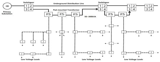
Figure 3.
Underground distribution system (Current).
2.3. RMU Method for Strengthening Reliability
The introduction of an RMU-based method is being considered in the underground distribution system. The RMU is a PDE for constructing a ring-type distribution system. It includes a circuit breaker function to protect the PDE connected to the RMU and isolate the D/Ls in case of faults. This method can be applied when building a more reliable system [14].
Figure 4 illustrates the configuration of the S-substation where the RMU method is applied. The S-substation is not connected to the main D/L connected to other D/Ls or the HV Loads but only to the branch D/L. This S-substation has an RMU, a transformer, and an LV board in the same underground structure [12].
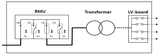
Figure 4.
S-Substation with PDE.
3. Three Types of Distribution System Models
This paper proposes three types of distribution system models for the S-substation.
3.1. Model A (Dual S-Substation)
The first model is composed of supplying power to each S-substation by installing two S-substations. For instance, if one transformer experiences a fault, the power can be supplied by replacing the transformer installed in another S-substation. In this case, after detecting a fault in the transformers installed in the two S-substations, power cut-off/power-on through ATCB should be performed to minimize fault. This model allows loads to be shared between S-substations. Therefore, in the event of a fault, the transformer installed in one S-substation shares all the loads, so it is important to consider the load factor of the transformers. Model A is shown in Figure 5.
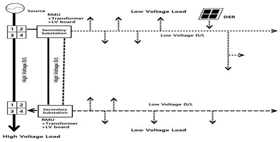
Figure 5.
Underground distribution systems based on model A.
3.2. Model B (Auxiliary Transformer)
Model B involves installing two transformers in the S-substation. In this approach, power is primarily supplied by one transformer, and in the case of a transformer fault, the power is switched and supplied with an auxiliary transformer installed in the same S-substation. In this model, since two transformers are housed simultaneously in the S-substation, it has the advantage of reducing the replacement time in the case of a peripheral voltage fault compared to Model A, thus improving reliability. Model B is shown in Figure 6.
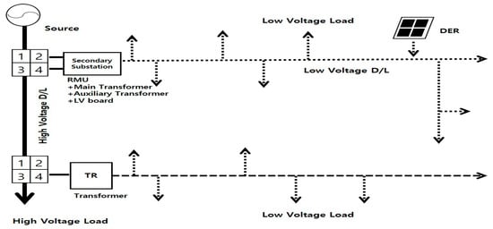
Figure 6.
Underground distribution system based on model B.
However, since two transformers are installed in a single S-substation, not only does it take up significant space, but due to space constraints, it can also cause problems such as ventilation and waterproofing.
3.3. Model C (Pad Transformer and S-Substation Connection)
In the case of Model C, only one S-substation is applied to the existing underground distribution system. Model A installs two substations, whereas this model utilizes only one. It is considered that this model is suitable for existing subordinate consumers outside of housing site development districts due to the limitations associated with the installation of underground structures. The current underground D/Ls are a type in which one to four transformers are connected to one terminal of a four-circuit switchgear, and the switchgear does not have a circuit-breaking function, as shown in Figure 3. Model C switches the power source during a power outage via the ATCB upon detecting a fault of a transformer installed in the S-substation, reducing power outage time. Model C is shown in Figure 7.
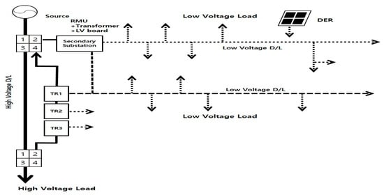
Figure 7.
Underground distribution system based on model C.
4. Power Flow and Parameters
4.1. Power Flow
4.1.1. Definition
PF is a numerical analysis of the flow of electric power in interconnected power systems. In this paper, the PF is analyzed using MATLAB/SIMULINK, which calculates the PF using the Newton–Raphson method [15].
4.1.2. Direction of Power Flow
The key parameters of interest in the PF results in MATLAB/SIMULINK are voltage and phase. Each load is connected in parallel and must be supplied with the specified voltage. The phase information can also tell the direction of the tide. In MATLAB/SIMULINK, the phase is displayed in degree units, and one can observe the difference in the direction and time of the tide by looking at the difference in phase.
Figure 8 depicts the distribution system as a π-type equivalent circuit, with and representing the sending-end voltage and current and and representing the receiving-end voltage and current. denotes the total series impedance, while represents the total shunt admittance. Additionally, δ represents the voltage-phase angle between the sending and receiving ends. From the above equations, it can be seen that, in AC, the active PFs come from the point where the phase is leading to the point where it is lagging [16]. In MATLAB/SIMULINK, the slack value is typically set as 1∠0, so the load side can be expected to come out as a negative value.
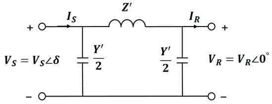
Figure 8.
Simple power system equivalent circuit.
Figure 9 illustrates a waveform for active power. For example, if the phase angle at Bus 1-2 is 0 deg but there is a difference of −0.01 deg in Bus 1-3, which is the subsequent load, it would be necessary to verify whether power is supplied after a few seconds.
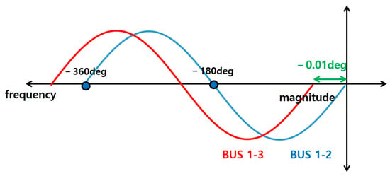
Figure 9.
Example of the phase difference of load bus.
As shown in the above equation, since the power system in Korea uses 60 Hz, 1 cycle can be regarded as 16.7 ms; therefore, based on the above formula, a phase angle difference of 0.01 deg corresponds to 0.4638 μs.
4.2. Standard Voltage
In the distribution system, the loads are connected in parallel. A parallel load is a connection method in which the voltage is the same and the current varies depending on the load. The standard voltage ranges are listed in Table 1.

Table 1.
Standard voltage ranges in Korea.
From the above standard, it can be seen that the voltages must be maintained from 207 V to 238 V for single-phase 220 V and from 342 V to 418 V for three-phase 380 V.
Proper arrangement of the loads is required to maintain the standard voltage ranges to the loads connected at the end of the D/Ls. Even if the impedances of the D/Ls are small, a voltage drop occurs when the current is large, so it is preferable to connect heavy LV loads directly to a source (transformer). Figure 10 and Figure 11 illustrate this concept.

Figure 10.
Calculation formula for voltage drop D/L.
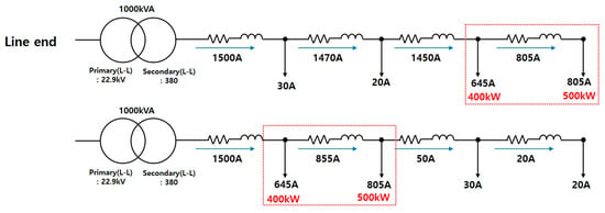
Figure 11.
Comparison of load displacement.
In MATLAB/SIMULINK, one can set the voltage value of the slack bus to 1 [pu] and calculate the PF, which allows one to determine the amount of voltage drop that occurred as a result of the calculation.
4.3. Load Placement
This paper analyzes in detail the load placement that was briefly addressed in “B. Standard Voltage.” The kVA ratings of the transformer installed in the S-substation are 500, 1000, and 2000. Additionally, heavy LV loads are connected. In the LV, i.e., on the transformer’s secondary side, the current varies according to the capacity of the loads, even though the voltage connected to the loads is the same.
For optimal load placement, this paper analyzes how the voltage drop changed for three cases: ① direct connection to the transformer, ② end of the D/L, ③ separation connection. To calculate the voltage drop for each of the three cases, the configuration in Model A is modified in the proposed system types. The first case is that heavy LV loads (250~500 kW) are directly connected to the transformer’s secondary side (directly under the transformer), and the second case is that the heavy LV loads are connected to the end of the D/L. The third is separately connected to other LV loads. Additionally, in the third case, the branch D/L is long, so the line impedances are set to be large [12]. Figure 12 describes the simulation results.
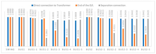
Figure 12.
Bus voltage drop cases.
The voltage is expressed as a PU value and the specified voltage maintenance range must be 0.855 [pu] or higher; however, when connected with heavy LV loads at the end of the D/L, there is a significant voltage drop from Bus 1-3/2-3, making it difficult to maintain Power Quality (PQ). When heavy LV loads are directly connected to the transformer, the specified voltage is maintained (0.855 pu) in all buses. In contrast, when connected to the end of the D/L, it is observed that the voltage drops rapidly from Bus 1-3. In the case of a separate line configuration, Bus 1-2 is configured as a bus on a separate line rather than on the existing line. The simulation results indicate that the optimal arrangement is to connect heavy LV loads directly under the transformer’s secondary side. The transformer’s secondary side current and voltage drop can be expressed using the following formula.
A rated current of 1500 A is calculated while assuming the transformer capacity is 1000 kVA. As indicated by the above equations, when heavy LV loads are connected to the end of the D/L, the current of heavy loads flows through the D/L, thus resulting in a voltage drop due to line impedance, which shows that the specified voltage cannot be maintained; therefore, in the system model presented in this paper, the PF is analyzed while assuming that all heavy LV loads are placed directly under the transformer.
Several LV loads are connected to the bus. These are General (, Residential (, Educational (, Industrial (, and Agricultural ( Loads. These loads are connected to each bus [17].
5. Analysis of Power Flow by Model
5.1. Model A
Figure 13 shows the equivalent circuit of Model A, and Table 2 lists the results of PF when it is operated in a normal state (steady state) without any fault or conversion. As shown in Table 2, it can be observed that there are cases where it does not reach standard 1 [PU]. In this simulation, since the transformer’s secondary side is set to 380 V, if it is 0.8808 of Bus 1-5, which is the lowest value, 380 × 0.8808 = 334 V, which is lower than the standard voltage range; however, since the actual transformer supplies the secondary at 400 V, it can be seen that it is necessary to maintain up to 342/400 V = 0.855 [PU] to maintain 342 V (380 ± 38 V), which is the minimum standard voltage. That is, the simulation results show that the load connected to each BUS is receiving power within the standard voltage range. To compare the PF results for the three models, it is necessary to examine not only the steady-state operation (Normal state) but also the operating conditions under other scenarios. In this paper, we review the following conditions: (1) Normal state, (2) Line switching, and (3) Dual Line. Additionally, changes in voltage and phase due to the connection of DERs are compared.
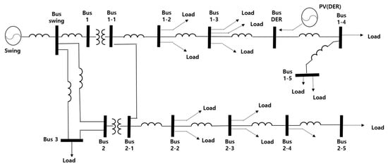
Figure 13.
Underground distribution system based on model A.

Table 2.
Comparison of power flow result by model A.
The table above lists the PF results for all cases [12]. As a result of the simulation, it can be confirmed that most of the methods of supplying power from an auxiliary source after the main power source is cut off cause voltage drop and the phase delay. In the case of parallel operation of transformers, dual power is supplied to the loads. Moreover, when DER is connected, a power source is present midway along the D/L other than the Slack (main source). Therefore, when DER is operational, it can be understood that the voltage of the D/L increases and the phase becomes faster. To facilitate understanding, the paper presents the following comparative graphs (Refer to Figure 14).
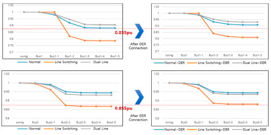
Figure 14.
Power flow comparison graphs based on model A.
The upper graph shows the voltage value for each bus for line No. 1 to which the DER is connected, while the lower graph shows the voltage value for each bus to which the DER is not connected. The simulation for the second type of Line Switching sets the route where the power supply of the transformer supplying line 1 is cut off, so it can be confirmed that power is supplied when it is supplied from the transformer of line 2 after the power is cut off, but the voltage drop, in this case, is very large. Although the power in line 2 is not cut off, it can be confirmed that loads of line 2 are also affected because it also divides the line 1 loads. The graph on the right of the upper/lower graph shows how the voltage changes when DER is connected. It can be seen that the voltage increases when DER is applied to both lines 1 and 2. In this paper, the DER is configured to 99 kW. If additional DERs are connected, the voltage drop can be further compensated.
From the results, it can be seen that parallel operation is the most effective configuration for maintaining PQ, and when DER is connected, the phase becomes faster. Buses 1 and 2 represent the HV terminal on the primary side of the transformer. Buses 1-1 and 2-1 represent the transformer’s secondary side, while loads are connected from Buses 1-2 and 2-2.
As shown in the table and graph, if we compare buses 1-2 and 2-2 with buses 1-3 and 2-3, it can be seen that the phase is significantly left behind. This is because heavy LV loads are connected to the 1-2 and 2-2 buses, and the phase from the next bus is delayed; that is, when heavy LV loads are connected, it can be seen that the flow of the current is delayed.
Figure 15 demonstrates that the first line is bus 1, followed by buses 1-2 and 2-2, and the last line is bus 2-5; that is, Bus 1 > 2 >> 1-1 > 2-1 > 2-2 > 1-2 >> 2-3 > 2-4 > 2-5 >> 1-3 > 1-4 > 1-5. This sequence highlights the differences in phase angles across the buses.
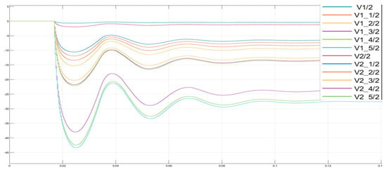
Figure 15.
Phase change over time based on the bus.
To determine the frequency change according to major events, (1) in 20 cycles, main transformer fault, (2) in 40 cycles, Line switching (to reduce power outage), (3) in 60 cycles, connecting DER, (4) in 80 cycles, recovery fault (with dual line state), (5) in 100 cycles, 1 phase ground fault (Refer to Figure 16). During most of these events, the frequency deviates from the specified frequency range, but it returns to normal immediately. The frequency drops when power is lost or the load factor increases; the frequency rises when power is supplied or DER is applied.
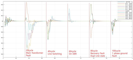
Figure 16.
Frequency changes according to specific orders.
The above simulation is conducted with each transformer operating at 70~90% of its rated load; therefore, it is noticeable that the voltage drop is large when switching power to another transformer due to a transformer fault. It is necessary to examine how the PF changes according to the transformer load factor. To this end, the load factor is adjusted to 50% or less and the simulation is performed again.
The results of the analyses are presented in the following Figure 17.
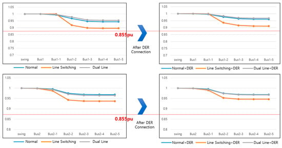
Figure 17.
Change in power flow after adjusting the loads.
The above graph shows that when the loads are maintained within 50%, the standard voltage range is maintained without a significant decrease in voltage even in the case of Line switching.
5.2. Model B
In the second model, B, the main and auxiliary transformers are installed simultaneously in the same S-substation. The Figure 18 is represented as an example circuit for easy understanding.
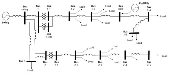
Figure 18.
Underground distribution system based on model B.
In this model, the 1000 kVA transformer for the upper line is supplied under normal conditions, and in the event of a fault in D/Ls due to a transformer fault, the loads are switched and supplied to the auxiliary transformer; in other words, the auxiliary transformer is normally operated with no load, and it is only operated with loads applied when there is a transformer fault.
To maintain the standard voltage in Model A in this paper, a value of 0.855 [pu] should be maintained. As a result of the simulation, the loads connected to each bus do not satisfy 0.855 [pu]. Of course, this sample drawing also satisfies the standard because the load arrangement and impedance are considered such that 0.855 [pu] or more is obtained in the normal state.
Next, let us identify the situation where the main transformer fault, which is not in the normal state, and the parallel operation in which the main/auxiliary transformer is operated at the same time using the Table 3 below.

Table 3.
Comparison of power flow results by case.
The data in the table are shown in the form of Figure 19 as follows:
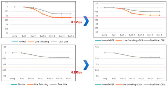
Figure 19.
Power flow comparison graphs based on model B.
From the table and graphs, it is evident that the voltage and phase values are the same in the normal state and the line connection as a result of the PF calculation. The auxiliary transformer does not have other loads and it has the same capacity.
In the case of parallel operation of transformers, the load capacity is enough to supply one transformer, and as two transformers are connected, the load factor is lowered as a result; therefore, as a result of the simulation, it can be seen that the voltage is close to the reference voltage and the phase is fast, meaning that fast power supply is possible.
For line 2 (bottom), as a line that is irrelevant to the load switching and parallel operation of line 1, all three cases (normal, connected, parallel) show the same waveform.
As analyzed in Model A, buses 1 and 2 represent the HV terminal as the primary side of the transformer. Buses 1-1 and 2-1 are the transformer’s secondary side, and the loads are connected from buses 1-2 and 2-2. As shown in the table, if one compares buses 1-2 and 2-2 with buses 1-3 and 2-3, it can be seen that the phase is largely left behind. This is because heavy LV loads are connected to buses 1-2 and 2-2, and the phase from the next bus is delayed; that is, it can be seen that when heavy loads are connected, the PF is delayed.
5.3. Model C
The last Model C is a system wherein only one S-substation is installed and connected to an existing transformer in the case of a transformer fault. To maintain the load at almost the same as that of other models and to match the capacity of the existing transformer to the 300 kVA that is typically used, only the heavy LV loads are partially adjusted. Figure 20 shows the equivalent circuit of Model C.
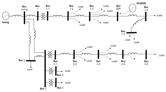
Figure 20.
Underground distribution system based on model C.
Similar to other system models, the PF results for each Model C situation are shown in the following Table 4.

Table 4.
Comparison of power flow results by case.
Under normal operational state, there is no difference from other models, so the set standard voltage is maintained; however, the voltage drop appears to be larger when switching to another transformer due to a fault in the transformer installed in the S-substation. Although the voltage drop in the load connected to line 1 (top) is large, the voltage drop in the load connected to line 2 (bottom) is also large, so a normal power supply cannot be said to have been achieved. This is judged to be a problem that occurs because the transformer installed in the S-substation is operated at 1000 kVA, whereas the existing pad-mounted transformer is operated at 300 kVA.
As shown in the PF results (Table 4 and Figure 21), since there are more loads connected to the 1000 kVA transformer, it is not appropriate to only connect to the 300 kVA transformer; therefore, when three 300 kVA transformers in operation are connected or two 500 kVA transformers are connected, the loads must be switched to the connected transformer when there is a fault in the 1000 kVA transformer; furthermore, to maintain standard voltage, the load factor of the transformer should be limited to 50% or less. The PF results when three 300 kVA transformers are connected and the load factor is less than 50% are as following Figure 22.
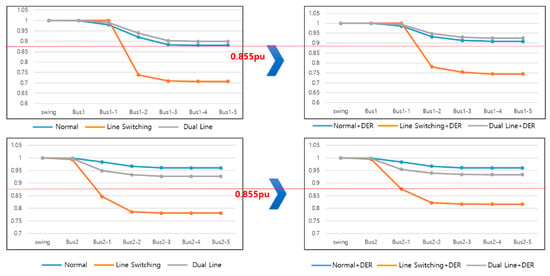
Figure 21.
Power flow comparison graphs based on model C.
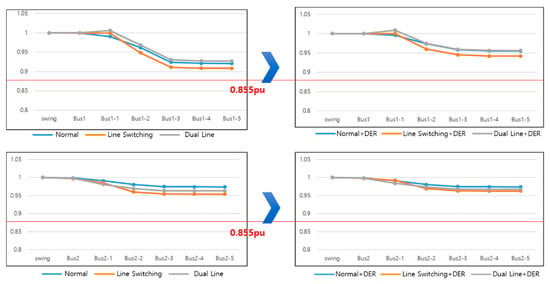
Figure 22.
Power flow change graphs after 50% load factor.
When three 300 kVA transformers are connected and the load factor is kept below 50%, it can be confirmed that power is supplied stably.
6. Economic Analysis
6.1. Economic Analysis Issues
This paper also examines construction cost and VOLL for economic analysis [18].
6.2. Construction Cost
To calculate the construction cost, the quantity of equipment, cable length, management, etc., should be decided by models. The equipment output for Model A is as follows in Figure 23:
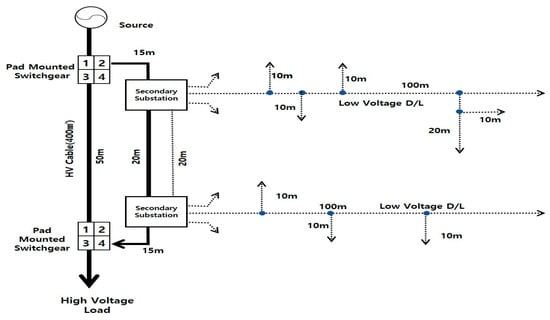
Figure 23.
Required quantity of each piece of equipment for model A.
The equipment and materials for each model are as follows in Table 5:

Table 5.
Equipment and materials required.
Calculations for the construction costs are presented in the following Table 6:

Table 6.
Calculations of construction costs.
The results indicate that Model C has the highest construction cost, which is attributable to the large number of transformers and the increase in cables caused by line connections. In contrast, Model A, which involves the installation of two nearby S-substations, has the lowest construction cost and is economical.
6.3. Value of Lost Load
The Value of Lost Load (VOLL) represents the monetary cost associated with all the consequences that arise when consumers pay for electricity but do not receive it. For example, in the event of a power outage, VOLL includes the costs of damage and repairs to products under production due to the interruption of the power supply, labor costs incurred from work stoppages, additional expenses related to business resumption, fuel costs from operating emergency generators, and losses such as the death of livestock due to interrupted oxygen supply or fish mortality. Essentially, VOLL encompasses any costs expected by customers due to power outage. The formula for each industry is as follows in Table 7:

Table 7.
VOLL function cost.
Where X is the power outage duration time; if it is less than 1 min, it is calculated as 1 min. The calculated results are as follows in Table 8:

Table 8.
VOLL cost per hour and use.
The formula is converted into a function by examining the amount of damage that is expected by the consumer when a power outage occurs. It is observed that, for short power outages, the amount of damage is large for industrial and general loads, while it increases rapidly over a long period of time for agricultural loads; for example, if the oxygen supply in aquaculture farms is interrupted due to a power outage, it may lead to huge damages, such as mass death.
The basic analysis is set on the premise that the ATCB is put in immediately after the occurrence of a fault; however, the operation time of the ATCB should be taken into account—the manufacturer’s performance is confirmed to be 15 ms.
Due to the phase difference for each bus, the supply time is different even when the power is turned on again; however, as can be seen in the Table 9, the convert to time for each bus is very small compared to the operation time of the ATCB, so it has little effect.

Table 9.
VOLL cost of model A.
7. Results and Discussion
7.1. Selecting the Optimal Distribution System
An optimal model is selected based on the results of the review of the PF by system model and economic analysis. The analysis results based on models are shown in Table 10.

Table 10.
Analysis results based on models.
The detailed analysis results are as follows:
7.1.1. Distribution System
- The currents of Model A~C are stable in normal operation without fault in D/Ls.
- The PF analysis indicates that the parallel operation of transformers appears to be the optimal operation method.
- It is difficult to supply stable power due to voltage drop during load switching due to transformer faults. → Normal power supply is possible when the transformer load is operated at less than 50% capacity.
- Heavy LV loads (2~500 kW) need to be kept close to the transformer in consideration of the voltage drop.
7.1.2. Economics
- Model A has the lowest construction cost and Model C has the highest.
- Construction cost is affected by the number of structures/equipment and the length of the D/Ls.
7.1.3. Construction
- Since the S-substation is a structure installed underground, construction methods are also important.
- If an auxiliary transformer is installed, the area occupied increases, and if an ATCB is installed, additional area is required.
- In the case of Model C, the existing transformer is connected, but due to its heavy weight, many interconnected lines are required.
7.1.4. Optimal Model Selection
- As a result of the analysis, it is judged that Model A is the most suitable. Due to the characteristics of the S-substation, the transformer capacity is large, but they can be installed near each other to complement each other, and the construction efficiency can be improved by installing an underground structure nearby.
- In consideration of load arrangement, heavy LV loads should be placed close to the transformer, and the load factor should be kept below 50% in consideration of the transformer’s fault. Moreover, S-substations should be installed in proximity to each other to reduce the load factor and voltage drop. The detailed criteria are as follows [4,19]:
- ∙
- The transformer should be kept at under 50% of the load factor.
- ∙
- S-substations should be installed near heavy LV loads.
- ∙
- S-substations should be installed adjacent to each other.
- ∙
- Load arrangement should consider voltage drop.
- ∙
- LV boards should be installed to secure LV system reliability.
7.2. Example of Application of Model A of Power Distribution System
The underground distribution system to which Model A is applied is shown in Figure 24. It is different from Figure 3. When two S-substations are installed, it can be confirmed that they are connected through ATCB to prevent power outages. In addition, considering the voltage drop, heavy LV loads are placed close to the S-substation.
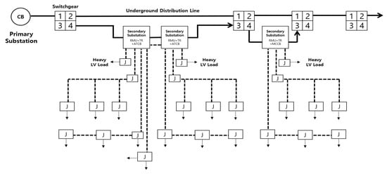
Figure 24.
Underground LV distribution system for S-Substation based on Model A.
8. Conclusions
This paper addresses the optimal LV distribution system for applying the S-Substation to an underground distribution system. Three models were proposed, and both PF and economic analysis were conducted to determine the optimal distribution system model. PF analysis was conducted to determine the voltage and phase of each model; additionally, frequency variations were observed. MATLAB/SIMULINK was utilized for accurate analysis, and changes in power flow were also examined with the connection of DERs.
In LV distribution systems, voltage drop must be considered based on load placement, as the voltage drop can vary depending on the location of heavy loads, potentially falling outside the standard voltage range at the end of the D/Ls; therefore, load placement was also considered in this study. The voltage and phase values from the PF analysis are derived from the BUS. To support this analysis, we examined the standard voltage ranges in Korea, strategies for load deployment to prevent voltage drops, and how phase differences change over time. For underground areas in Korea, it is crucial to consider the placement of the PDE once potential load locations are confirmed. Unlike the transmission system, the distribution system connects to various loads, including motor, nonlinear, and unbalanced loads. The loads could fluctuate in capacities and positions, causing PF results to change occasionally; additionally, since the S-substation is an underground structure, factors such as installation methods and securing underground space must be considered. Therefore, it is necessary to analyze the field conditions and PF specific to each location where the S-substation is installed. This is because construction costs fluctuate greatly depending on the field conditions.
Construction costs and VOLL were compared across the models for economic feasibility. The optimal location and selected model can be determined by incorporating the PF analysis results and economic feasibility discussed in this paper. Ultimately, Model A was selected as the optimal model. An exemplary system was presented to demonstrate the application of this model to the underground distribution system.
Korea is more sensitive to power outages and faults than other countries; therefore, reliable equipment and system configurations are increasingly important. To build a more reliable LV distribution system, the following areas of research should be considered:
- Underground LV closed-loop or multi-LV distribution systems.
- Power quality management in LV distribution systems.
- Protection coordination methods for LV distribution systems.
- Fault detection methods in LV distribution systems.
In the future, we believe that the models presented in this paper as well as other models can be studied and applied in the field.
Author Contributions
Conceptualization, B.S., H.L. and S.C.; methodology, B.S.; software, B.S.; validation, B.S. and H.L.; formal analysis, B.S. and H.L.; investigation, B.S. and H.L.; resources, B.S. and H.L.; data curation, B.S. and H.L.; writing—original draft preparation, B.S.; writing—review and editing, B.S. and S.C.; visualization, B.S.; supervision, S.C.; project administration, B.S.; funding acquisition, B.S. and S.C. All authors have read and agreed to the published version of the manuscript.
Funding
This work was supported in part by the Korea Electric Power Research Institute (KEPRI) grant funded by the Korea Electric Power Corporation (KEPCO) (R23DA01) and in part by the Korea Institute of Energy Technology Evaluation and Planning (KETEP) grant funded by the Ministry of Trade, Industry & Energy (MOTIE) of the Republic of Korea (No. RS-2023-00234707).
Institutional Review Board Statement
Not applicable.
Informed Consent Statement
Not applicable.
Data Availability Statement
The data used in this study were obtained from the Korea Power Exchange. The period for data disclosure has expired.
Conflicts of Interest
The authors declare no conflicts of interest.
References
- Shin, B.H.; Lee, H.S.; Shin, D.Y.; Hur, S.Y.; Kim, S.M. A study on the application of power electronics technology in secondary substation to improve power quality. In Proceedings of the 27th International Conference on Electricity Distribution (CIRED 2023), Rome, Italy, 12–15 June 2023. [Google Scholar]
- Zhu, Y.; Tomsovic, K. Optimal distribution power flow for systems with distributed energy resources. Int. J. Electr. Power Energy Syst. 2007, 29, 260–267. [Google Scholar] [CrossRef]
- Ibrahim, I.A.; Hossain, M.J. Low voltage distribution networks modeling and unbalanced (optimal) power flow: A comprehensive review. IEEE Access 2021, 9, 143026–143084. [Google Scholar] [CrossRef]
- Yang, C.; Sun, Y.; Zou, Y.; Zheng, F.; Liu, S.; Zhao, B.; Wu, M.; Cui, H. Optimal power flow in distribution network: A review on problem formulation and optimization methods. Energies 2023, 16, 5974. [Google Scholar] [CrossRef]
- Chamorro, H.; Diaz, N. Hierarchical power flow control in low voltage microgrids. In Proceedings of the 2013 North American Power Symposium (NAPS), Manhattan, KS, USA, 22–24 September 2013; IEEE: New York, NY, USA, 2013; pp. 1–5. [Google Scholar]
- Stanelytė, D.; Radziukynas, V. Analysis of voltage and reactive power algorithms in low voltage networks. Energies 2022, 15, 1843. [Google Scholar] [CrossRef]
- Babś, A.; Matusewicz, M.; Noske, S.; Falkowski, D. Smart Secondary Substation as the source of the flexibility services. In Proceedings of the CIRED 2021-The 26th International Conference and Exhibition on Electricity Distribution, Online Conference, 20–23 September 2021; IET: New York, NY, USA, 2021; pp. 477–480. [Google Scholar]
- Apellaniz, I.; Arostegui, J.; Tejedo, J.R.; Sánchez, J.A. Smart Secondary Substation. A reality and a big opportunity for innovative solutions for predictive maintenance and life extension. In Proceedings of the 25th International Conference on Electricity Distribution, Madrid, Spain, 3–6 June2019. [Google Scholar]
- Bjørtuft, T.R.; Granhaug, O.; Hagen, S.T.; Kuhlefelt, J.H.; Salge, G.; Skryten, P.K.; Stangherlin, S. Internal arc fault testing of gas insulated metal enclosed MV switchgear. In Proceedings of the CIRED 2005-18th International Conference and Exhibition on Electricity Distribution, Turin, Italy, 6–9 June 2005; IET: New York, NY, USA, 2005; pp. 1–5. [Google Scholar]
- Cho, H.; Lee, U.; Park, Y. The temperature distribution and rise test of pole mount cast resin transformer for power distribution. In Proceedings of the IEEE/PES Transmission and Distribution Conference and Exhibition, Yokohama, Japan, 6–10 October 2002; IEEE: New York, NY, USA, 2002; pp. 1854–1857. [Google Scholar]
- Liu, X.; Wang, J.; Sun, J. Temperature rise test and calculation method of liquid-immersed transformer. In Proceedings of the 2022 IEEE International Conference on High Voltage Engineering and Applications (ICHVE), Chongqing, China, 25–29 September 2022; IEEE: New York, NY, USA, 2022; pp. 1–4. [Google Scholar]
- Shin, B.H.; Oh, G.D.; Kim, S.C.; Jung, K.H. Power Flow and Economics Analysis for RMU-based Low-voltage Distribution Networks Operation. In Proceedings of the CIRED 2021-The 26th International Conference and Exhibition on Electricity Distribution, Online Conference, 20–23 September 2021; IET: New York, NY, USA, 2021; pp. 2432–2436. [Google Scholar]
- Marszal-Pomianowska, A.; Widén, J.; Le Dréau, J.; Heiselberg, P.; Bak-Jensen, B.; de Cerio Mendaza, I.D. Operation of power distribution networks with new and flexible loads: A case of existing residential low voltage network. Energy 2020, 202, 117715. [Google Scholar] [CrossRef]
- Ring Main Unit in Electrical Distribution System. Available online: https://www.allumiax.com/blog/ring-main-unit-in-electrical-distribution-system (accessed on 17 August 2024.).
- Etta, B.-O.; Idoniboyeobu, D. Improved Performance of Elelenwo 11kv Electric Power Distribution Network Using Newton Raphson Load Flow. IRE J. 2021, 5, 19–25. [Google Scholar]
- Glover, J.D.; Mulukutla, T.J.O.; Sarma, S. POWER SYSTEM Analysis & Design; CENGAGE Learning: Boston, MA, USA, 2017; pp. 310–403. [Google Scholar]
- Heidari-Akhijahani, A.; Safdarian, A.; Vrakopoulou, M. A linear ac power flow model for unbalanced multi-phase distribution networks based on current injection equations. IEEE Trans. Power Syst. 2021, 36, 3806–3809. [Google Scholar] [CrossRef]
- Tsao, Y.-C.; Beyene, T.D.; Thanh, V.-V.; Gebeyehu, S.G.; Kuo, T.-C. Power distribution network design considering the distributed generations and differential and dynamic pricing. Energy 2022, 241, 122828. [Google Scholar] [CrossRef]
- Seme, S.; Lukač, N.; Štumberger, B.; Hadžiselimović, M. Power quality experimental analysis of grid-connected photovoltaic systems in urban distribution networks. Energy 2017, 139, 1261–1266. [Google Scholar] [CrossRef]
Disclaimer/Publisher’s Note: The statements, opinions and data contained in all publications are solely those of the individual author(s) and contributor(s) and not of MDPI and/or the editor(s). MDPI and/or the editor(s) disclaim responsibility for any injury to people or property resulting from any ideas, methods, instructions or products referred to in the content. |
© 2024 by the authors. Licensee MDPI, Basel, Switzerland. This article is an open access article distributed under the terms and conditions of the Creative Commons Attribution (CC BY) license (https://creativecommons.org/licenses/by/4.0/).