Abstract
The efficiency of standalone photovoltaic (PV) systems heavily relies on the effectiveness of their maximum power point tracking (MPPT) controller. This study aims to improve the operational efficiency and reliability of standalone PV systems by introducing a novel control scheme, the Immersion and Invariance Neural Network (II-NN). This innovative system integrates a nonlinear estimator of solar irradiance with a neural network (NN) model, eliminating the need for direct irradiance measurements and associated costly sensors. The proposed methodology uses the Immersion and Invariance algorithm to design a nonlinear estimator that leverages the real-time measurements of PV current and voltage to estimate the incident irradiance. The NN then processes this estimated irradiance to determine the MPP voltage accurately. A robust nonlinear controller ensures the PV system operates at the MPP. This approach stands out by managing the nonlinearities, parametric uncertainties, and dynamic variations in PV systems without relying on direct irradiance measurements. The II-NN system was rigorously tested and validated under real climatic conditions, providing a realistic performance assessment. The principal results show that the II-NN system achieves a mean error of 0.0183V and a mean absolute percentage error of 0.3913%, with an overall MPPT efficiency of up to 99.84%. Comparisons with the existing methods, including perturb and observe, incremental conductance, and three other recent algorithms, reveal that the II-NN system outperforms these alternatives. The major conclusion is that the II-NN algorithm significantly enhances the operational efficiency of PV systems while simplifying their implementation, making them more cost-effective and accessible. This study substantially contributes to PV system control by advancing a robust, intelligent, and sensorless MPPT control scheme that maintains high performance even under varying and unpredictable climatic conditions.
1. Introduction
The world is grappling with severe climatic challenges, including global warming and climate change, predominantly driven by the emission of greenhouse gasses from conventional energy sources. As a critical response to these issues, renewable energy is increasingly advocated as an essential and effective solution. By transitioning to cleaner, sustainable energy alternatives, these environmental impacts can be mitigated so as to pave the way for a more resilient and eco-friendly future [1,2,3]. Solar energy harnessed through photovoltaic (PV) systems has gained widespread recognition as an efficient and viable renewable energy solution. In recent years, extensive research and technological advancements have focused on enhancing PV cell efficiency and improving the overall operational performance of PV systems [4,5,6]. One of the primary challenges associated with PV systems is the variability of environmental resources, which has been identified as a significant constraint [7,8]. This inherent variability introduces stochastic behavior into the operation of PV systems, complicating the maintenance of consistent energy output. The maximum power point (MPP) represents the optimal point at which maximum energy can be extracted from a PV module [9,10]. However, due to fluctuating climatic conditions, this MPP is subject to stochastic variations, which can adversely affect the operational efficiency of the PV system if not properly managed [11]. Research indicates that the integration of MPPT algorithms into PV systems offers a robust solution to mitigate efficiency fluctuations caused by environmental variability [12]. MPPT algorithms dynamically adjust the operating parameters of PV systems to consistently maintain the MPP, thereby enhancing the system’s efficiency and reliability. The following literature review offers a comprehensive examination of the current landscape of MPPT algorithms. It delves into their development, functionality, and application within PV systems, highlighting key advancements and challenges. This review synthesizes the latest research findings, providing valuable insights into the effectiveness and efficiency of various MPPT techniques in optimizing the energy output of PV systems amidst fluctuating environmental conditions.
1.1. Literature Review
Three important MPPT strategies for increasing PV system efficiency are fractional open circuit voltage (FOCV), fractional short circuit current (FSCC), and pilot cell MPPT [13,14,15]. FOCV estimates the MPP as a fraction of the open circuit voltage, making it simple and inexpensive but susceptible to mistakes under changing conditions due to its fixed proportional constant. FSCC approximates MPP using a fraction of the short circuit current, providing a similarly simple and cost-effective solution; however, it necessitates frequent power interruptions for current measurement and may be inaccurate in variable situations. The pilot cell approach simulates the circumstances of the main array using a smaller PV cell, allowing for real-time tracking and adaption to changing settings without halting power generation; however, the additional hardware required increases complexity and maintenance needs. The trade-offs in cost, complexity, and accuracy underline the necessity of choosing the right approach for a given application and environment. To overcome the limitations associated with fractional open circuit voltage (FOCV), fractional short circuit current (FSCC), and pilot cell-based MPPT methods, ongoing research has been exploring advanced algorithms to further enhance the efficiency of PV systems. These emerging MPPT algorithms aim to improve accuracy, adapt to rapidly changing environmental conditions, and optimize energy harvest, thereby addressing the inefficiencies and constraints posed by traditional methods. Unlike the estimation of the MPP, perturb and observe (P&O) and incremental conductance (INC) are remarkable for systematically searching the MPP. P&O operates by perturbing the system’s voltage and analyzing the consequent changes in power as it approaches the maximum power point (MPP). Its merits are its simplicity and ease of implementation; nonetheless, it can experience oscillations around the MPP and struggle under quickly changing environmental circumstances, resulting in inefficient power extraction [16,17]. The INC algorithm, on the other hand, analyzes the power derivative with respect to voltage and changes the operating point to better track the MPP, even under variable irradiance levels. While INC is more accurate and responsive to change, it involves more complicated calculations and is prone to mistakes in noisy situations [18]. Both the INC and P&O face a trade-off between tracking speed and oscillation which compromises the overall efficiency of the MPPT. Researchers have proposed several variants of the P&O and the INC in order to address their limitation, especially under changing climatic conditions. For instance, an enhanced P&O was derived by adapting the perturbation duty cycle using the Pythagoras theorem [19]. Implemented on a boost converter, the researchers found that the overall MPPT algorithm enabled the system to gain in speed and efficiency. The beta theory was prescribed and extensively studied in [20,21,22] as a method for solving the trade-off problem inherent in the INC and P&O. Rather than directly targeting the MPP, it initially seeks an intermediary variable termed beta which will guide the system to a proximity of the MPP after which the final search for the actual MPP is achieved through a conventional algorithm. The approach allows the PV system to reach MPP without a trade-off. However, because of its dependence on conventional algorithms, the beta-inspired method inherits the problems of the conventional algorithms around the vicinity of the MPP.
It is important to note that MPPT methods relying solely on conventional approaches cannot ensure a robust response for PV systems. This limitation arises because these algorithms primarily focus on optimizing steady-state performance, often neglecting the critical transient response. Given that PV systems exhibit nonlinear behavior with an underdamped response, it is essential to manage transient dynamics effectively. To address this, coupling a suitable controller with the MPPT algorithm is necessary to regulate the transient response and enhance the overall stability and efficiency of the PV system. In this light, a PID controller was studied in a standalone PV system to address the issues related to PV robustness [23]. While the controller reveals an interesting performance, robustness is not totally guaranteed due to the linear nature of the PID in the face of a nonlinear PV plant. Another fundamental flaw of the latter research is its dependence on irradiance measurements for MPP estimation. Integrating an irradiance measurement unit in a PV system is not only expensive but also very complex [24]. The authors of [25] proposed a method that integrates a dynamic fractional-order perturb and observe (P&O) algorithm with a fractional proportional–integral controller, optimized using the hunter–pray optimizer. This innovative combination aims to improve the dynamic response of PV systems, minimizing power tracking oscillations that occur due to rapid changes in environmental factors such as solar irradiance. Recently, a number of modern control techniques have been prescribed for PV systems among which backstepping has emerged as a competent nonlinear controller. For instance, the researcher in [26,27] understudied a PV system controlled through the backstepping methodology. Their primary conclusions indicate that the backstepping scheme is a robust and adequate solution for managing the nonlinear extremities imposed by the PV plant. They showed this control scheme achieves better performance than the sliding mode and fuzzy logic control. However, the primary limitation of their work goes back to the issue of irradiance measurement dependency. This shows that the problem of irradiance dependency is prevalent. The prevalent issue of irradiance dependency in photovoltaic systems underscores the necessity for innovative solutions. To facilitate the advancement of PV technology, it is imperative to adopt control schemes that do not rely on irradiance sensors. A significant effort towards this objective has been documented in [28], where the authors implemented the incremental conductance method to determine the MPP voltage. This approach effectively bypasses the requirement for an irradiance sensor. However, it introduces a new dependency on the conventional algorithm, thereby inheriting the inherent limitations and challenges associated with the INC method.
Recent advances in MPPT techniques have spotlighted the concept of search space confinement as a means to boost the efficiency of PV systems [29]. For instance, the study conducted by the researchers in [30,31] illustrated that by limiting the search space to merely 10% of its original scope before implementing a conventional algorithm, significant improvements in tracking performance are realized. Furthermore, other researchers in [32] found that narrowing the search space to just 2% of its original extent further enhances PV system efficiency, demonstrating the potential of this approach to optimize power output more effectively. However, the dependence of these methods on conventional MPPT algorithms implies that they cannot guarantee sufficient robustness, especially under extreme operation conditions. Other approaches have integrated metaheuristics in the search for the MPP. Metaheuristic MPPT methods have emerged as a critical component in optimizing the performance of photovoltaic systems. These methods, inspired by natural processes and phenomena, aim to find the maximum power point under varying environmental conditions such as irradiance and temperature, thereby maximizing the efficiency of PV systems. Unlike traditional techniques, which can become locked in local optima (under partial shading) or need precise system modeling, metaheuristic approaches are resilient and adaptable to dynamic changes. Particle Swarm Optimization (PSO) [33], Genetic Algorithms (GAs) [34], Ant Colony Optimization (ACO) [35], and Differential Evolution (DE) [36] are some of the most often used metaheuristic algorithms, and they all use distinct methodologies to efficiently explore the solution space. PSO, for example, replicates the social behavior of birds flocking or fish schooling, with particles representing potential solutions adjusting their locations in response to personal and collective experiences. GA, which is based on natural selection and genetic principles, creates solutions via operations such as crossover, mutation, and selection. ACO, based on ant foraging behavior, uses pheromone trails to direct the search process to promising locations of the solution space. DE, which uses mutation, crossover, and selection processes, is noted for its simplicity and rapid convergence. These approaches are very successful in dealing with the nonlinear and complex nature of PV system characteristics, ensuring rapid convergence to the global MPP even under partial shade circumstances when many local maxima may occur. Despite their benefits, metaheuristic MPPT approaches have obstacles such as computational complexity, which can result in increased energy consumption and the requirement for more advanced processors.
1.2. Motivation
The primary motivation for undertaking this study is to significantly contribute to the field of PV systems by developing robust, intelligent, and irradiance sensorless MPPT control schemes. As highlighted in the existing literature, most MPPT algorithms struggle to ensure sufficient robustness when faced with the nonlinear characteristics of PV systems. While some methods do achieve the desired robustness, they often rely on the complex and expensive measurement of solar irradiance. The integration of such sensors not only adds a substantial financial burden but also increases the complexity of the PV system. This situation underscores the pressing need for developing irradiance sensorless MPPT schemes. Adopting such an approach promises not only to reduce costs but also to simplify the system, making it more flexible and accessible for broader applications. Through this study, we aim to bridge the gap in the existing MPPT solutions by providing a cost-effective and straightforward alternative that enhances the efficiency and reliability of PV systems without the need for cumbersome irradiance measurement units.
1.3. Contribution
In the spirit of addressing the pressing challenges previously highlighted, this paper details a standalone photovoltaic (PV) system equipped with a novel intelligent MPPT controller. The proposed controller aims to tackle two significant issues: (1) reducing the complexity of the PV system by determining the reference MPP voltage without relying on direct irradiance measurements, and (2) ensuring the robustness of the PV system under varying climatic conditions. As illustrated in Figure 1, the innovative MPPT technology integrates a synergetic combination of the II-NN algorithm and a robust nonlinear controller. The II-NN algorithm is a two-stage coupling of the Immersion and Invariance (I&I) technique, which is renowned for its efficacy in stabilizing nonlinear systems, with an artificial neural network (NN) model that estimates the reference MPP voltage. The robust nonlinear controller, designed using the backstepping methodology with integrated integral action, enhances the system’s resilience against unmodeled uncertainties and dynamic environmental changes. The II-NN algorithm effectively addresses the first objective by providing a reliable and efficient method for estimating the MPP voltage without the need for irradiance sensors. Meanwhile, the robust nonlinear controller ensures the system’s stability and robustness, fulfilling the second objective. The combined MPPT approach empowers the PV system to achieve and maintain the maximum power point tracking with strengthened stability and adaptability.
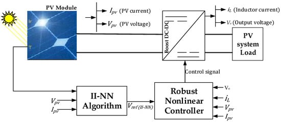
Figure 1.
Synoptic diagram of the proposed MPPT.
The overall system, as depicted in Figure 1, is implemented in MATLAB/Simulink R2018a and thoroughly examined under a range of diverse climatic conditions. Each subsystem is meticulously modeled and validated to ensure accuracy and reliability. Furthermore, experimental measurements were collected over the course of one day to provide real-world data for comparison. The proposed system, along with contemporary algorithms, was subjected to real climatic conditions to evaluate its performance comprehensively. The contributions of this paper can be summarized as follows:
- (1)
- Introducing a Novel Irradiance Sensorless II-NN Algorithm: This paper presents a new irradiance sensorless II-NN algorithm designed to determine the MPP voltage for PV systems efficiently, eliminating the need for costly and complex irradiance measurements.
- (2)
- Establishing a synergistic II-NN and Robust Nonlinear Controller: The study integrates the II-NN algorithm with a robust nonlinear controller to create a PV system that is not only robust and efficient but also simple to implement. This combination ensures the system can effectively handle varying and unpredictable climatic conditions while maintaining optimal performance.
- (3)
- Monitoring the Proposed MPPT System under Real Climatic Conditions: The proposed MPPT system is monitored and evaluated under actual climatic conditions, providing empirical evidence of its effectiveness and reliability in real-world applications.
- (4)
- Comparative Analysis with established and Recent MPPT Methods: The proposed MPPT system’s performance is compared against five methods, including perturb and observe (P&O) and incremental conductance (INC), as well as the most recent methods published in references [28,30,37].
The rest of this paper is structured as follows: The modeling and data collection procedure is presented in Section 2. In Section 3, the intelligent approach for MPP voltage estimation is presented. The design of the proposed nonlinear controller as well as the discussion on the overall system are presented in Section 4. The results of this paper are presented in Section 5, while the paper is concluded in Section 6.
2. Modeling of PV System and Data Collection
Modeling is crucial in order to comprehensively study a PV system. This section discusses the modeling of the PV panel as well as the data collection procedure. Several models do exist for the solar panel according to complexity and performance [38,39]. However, the single-diode model (SDM) is widely used in the MPPT studied due to its ability to strike a balance between complexity and performance [40]. Therefore, based on this rationale, the SDM is consistently adopted throughout the study. It has five parameters which have to be identified offline prior to the implementation of the PV system, namely the photocurrent, ; reverse saturation current, ; diode ideality factor, ; series resistance, ; and parallel resistance, . In this study, the MSX-60 solar panel is adopted for its popularity in PV system studies [12,39]. Its reference parameters are listed in Table 1. The next step involves determining the parameters of this solar panel. Several innovative optimization techniques have been published for identifying the parameters of solar panels. Thus, this study will not place further emphasis on that. However, this study employs a modeling approach which involves minimizing the discrepancy () between the datasheet values and computed variables of maximum power current, power, and short circuit current. To this end, our optimization object is related to the minimization of the errors due to the maximum variables obtained from the PV model and those provided from the nameplate of the manufacturer, written as follows:
where , , and are the corresponding maximum power, voltage, and current obtained online from the model. , , and are those provided by nameplate.

Table 1.
Nameplate information of Solarex MSX-60.
This study employs an intelligent algorithm, particle warm optimization, which is a well-known optimizer for minimizing the expression (1). After applying the protocol in Figure 2, it can be seen in Figure 3 that the objective function is effectively minimized, converging at the optimum value of . At this optimum point, the value of the 5-SDMs are identified as A, , and parallel resistance, By comparing the model current–voltage (I-V) curve with the experimental data, we can see that there is a good alignment (see Figure 3). This validation underscores the model’s suitability for the MPPT system. It is noted that the experimental data corresponds to data from the actual solar panel provided by the manufacturer, which can be easily extracted from the datasheet.
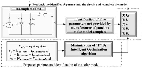
Figure 2.
Comprehensive block diagram describing the modeling procedure in this study.
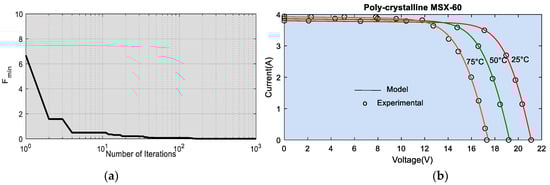
Figure 3.
Results of the PV modeling. (a) Optimization outcomes. (b) Comparison of model I-V curves with experimental data.
The validated or complete model is then used for data extraction. At this stage, the model is employed to extract data corresponding to the maximum power point voltage at different climatic conditions. These data will be subsequently used to train an NN model. The experimental setup used for the collection of these data is presented in Figure 4. Data collection is carried out by sweeping through the I-V curve from zero until the open circuit by means of a controlled voltage source. Thus, the point of interest, the MPP, is then extracted from the curve.
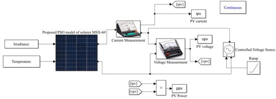
Figure 4.
Experimental setup for the online extraction of PV data.
Within the framework of data collection, 2079 data points are collected corresponding to 2079 different sweeps of the I-V curve. The climatic inputs are chosen so that the data collection covers a broad operation and realistic range. For this study, the irradiance data cover the range of 1 to 1000 W/m2, while temperature covers the range of 10 °C to 50 °C to. The data are obtained by incrementing the temperature from 10 °C to 50 °C in steps of 2 °C while keeping the irradiance constant. In the subsequent set, the irradiance is increased in steps of 10 W/m2. When this is performed, we obtain 2079 samples of irradiance (G) and temperature (T) data, plotted in Figure 5. The corresponding data extracted per sample condition is plotted in Figure 6. As seen, the voltage ranges from 0.7596 V to 18.73 V.

Figure 5.
Plot of climatic data. (Above) temperature. (Below) irradiance.
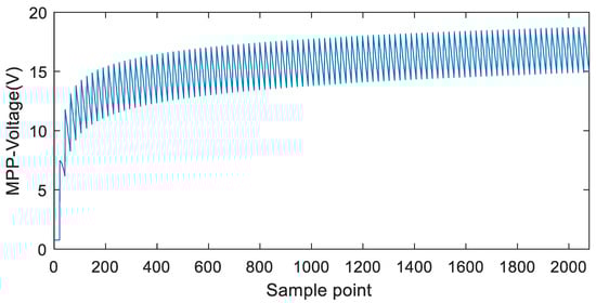
Figure 6.
Extracted MPP–voltage ( data from the data collection experiment.
3. Intelligent Sensorless Estimation of the MPP Voltage
This section delves into the development of a novel intelligent sensorless scheme designed for the rapid estimation of MPP voltage in PV systems. Unlike the existing methods, the proposed algorithm eliminates the need for irradiance measurement, which is both costly and complex to integrate into PV systems. This innovation highlights a significant advancement in sensorless PV technology, offering a more efficient and economical approach to optimizing energy capture in solar power systems. The proposed intelligent system is termed the II-NN algorithm, which is a synergetic combination of two compartments, namely the Immersion and Invariance (I&I) algorithm and an artificial neural network model (NN). The I&I is proposed for the real-time estimation of the irradiance on the PV module based on measurements of PV current, voltage, and temperature. The estimated irradiance ( is routed to the NN which will be trained to estimate the MPP voltage.
The I&I control algorithm is a robust and innovative control strategy designed to stabilize and control nonlinear dynamical systems by immersing the system into a lower-dimensional manifold where the desired dynamics are enforced [41,42]. The approach involves constructing a manifold that captures the desired system behavior and designing a controller that drives the system states to this manifold, ensuring invariance once the system states are on it. This technique provides a systematic way to handle uncertainties and nonlinearities, allowing for effective stabilization and performance improvement without requiring a full linearization of the system. The I&I method is particularly valuable for its ability to handle complex, high-dimensional systems and achieve the desired control objectives with reduced complexity.
If we consider a nonlinear system in its generalized form as follows: .
With standing for the state of the system, representing the fixed vector which denotes the uncertain parameters of the system, and being the control input. denote the real valued functions. There exists a constrained input for which the system’s dynamics are coordinated on a compact set. The control objective is the approximation of , written as . Thus, a manifold variable , which captures the desired system behavior, is designed as follows:
where the relation designed for which the term obeys strict monotonicity in That is, for all and , the following conditions are reached:
If the conditions prescribed in Equation (3) are reached, then the estimator’s updating law is obtained as follows:
We have and for which exist for all then the following is obtained:
In this vein, Equation (4) allows the desired manifold to be invariant and also asymptotically attractive. This describes the general structure of the I&O algorithm. In the subsequent lines, it will be applied to a PV system.
In the context of a PV system, we can establish the following equation derived from the circuit of an SDM:
where written as follows:
It is noted that is an introduced tern defined as follows:
where , , , , , , , , , , .
Note that is the number of series cells in the PV panel, is the charge constant, and is the diode ideality factor which is one of the 5 parameters of the DSM for the solar panel. is the Boltzmann’s constant, and is the number of parallel modules (in our study it is equal to 1). and are the irradiance and temperature at STC (standard test conditions), and and are the photocurrent and saturation current at standard test condition, which are the parameters which were determined previously. is the temperature coefficient of short circuit current (see Table 1). is the reference band gap energy computed according to [43]
The ultimate objective is to obtain the estimate of the real irradiance (G). The estimates irradiance is, therefore, labeled . According to the theory of I&I, the PV equation must be remodeled so as to fulfill strict monotonicity. This guides us to introduce the measurable variable:
Equation (10) is written as a nonlinear regression as follows:
Therefore, we have the following:
The update law for the estimator of G can be written as follows:
The following enforcement should be achieved:
Proof.
According to I&I, the strict monotonicity of is sufficient and necessary to show that Equation (14) holds. To this end, taking a partial derivative of Equation (12) yields the following:
□
A close examination of the terms confirms that they are real and positive. Based on this evidence, we can establish that Equation (21) follows a strictly monotonically increasing order, satisfying the following inequality:
In order to achieve our target goal, the estimator updating framework outlined in Equation (13) is implemented to estimate solar irradiance. The strength of this approach lies in its simplicity; it is not based on Lyapunov methods, making it very straightforward. The parameter is a positive gain which controls the convergence rate of the estimator, and it can be easily designed via the repeated observations of the estimator’s response. The estimated irradiance according to the I&I is routed to an NN. The overall implementation of the II-NN algorithm is presented in Figure 7, consisting of the I&I and the NN.
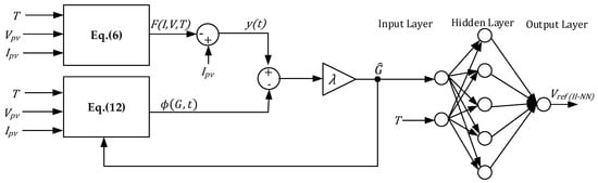
Figure 7.
Structure and implementation of the proposed II-NN algorithm.
Artificial neural networks (ANNs) are intelligent computational models inspired by the brain’s neural networks. They consist of interconnected “neurons” organized into layers, processing data similarly to biological networks. ANNs are crucial in machine learning and AI, used for pattern recognition, data classification, and regression. Structurally, they include an input layer, hidden layers for computations, and an output layer for final results. Neurons in each layer are connected through weighted connections and apply activation functions to output data. ANNs learn by adjusting these weights during training to minimize prediction errors, enabling machines to learn and make decisions like the human brain. Neural networks have received a lot of attention in the literature and more literature can be inferred in [44].
In this study, we maintain simplicity by limiting the complexity of the adopted NN. Thus, a simple NN is chosen made up of one hidden layer containing 5 neurons. The hidden layer is implemented with a sigmoid function while the output with a linear function. The inputs are the estimated irradiance () provided by the I&I, and temperature which can be easily and cost-effectively determined. The network is trained by Levenberg–Marquardt backpropagation algorithm. Prior to the training process, 70% of the collected data were used for training, while the rest were equally divided and used for validation and testing. The training, validation, and testing performance is presented in Figure 8, revealing the best validation performance of 7.0149 × 10⁻⁵ at 1000 epoch. The term “epoch” in this context refers to the number of complete cycles through the entire training dataset during the training process of the model. During each epoch, the model processes all the data points in the training set once, updating its internal parameters, such as weights and biases, to minimize the error function. This cycle allows the model to learn and adjust based on the patterns within the data.
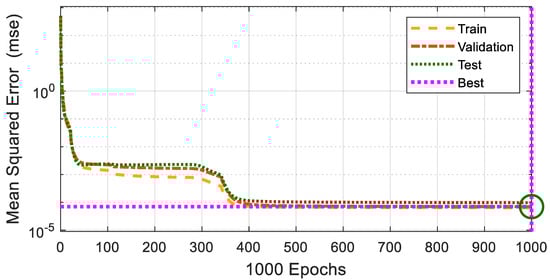
Figure 8.
Training, validation, and testing performance of the NN-Mean Squared Error (MSE) as a function of the epoch (number of training cycles considering all the training datasets per cycle).
The performance of the ANN can be further appraised from the regression plots. Upon testing the model with the complete 2079 dataset, a regression of 0.99999 is revealed (see Figure 9), underscoring the high performance of the NN model. The trained NN model is integrated into the II-NN architecture, as illustrated in the diagram presented in Figure 7. This figure provides a detailed depiction of the interaction between the II and the NN model, emphasizing the collaborative operation between these two components. Specifically, it highlights how the II serves as a bridge between the real-time measurements and the NN, ensuring that the estimated irradiance is accurately fed into the neural network. The NN then processes these data to estimate MPP. The diagram underscores the synergy between the II and the NN, where the II facilitates seamless data flow, while the neural network, leveraging its training, dynamically predicts the MPP voltage in varying conditions. This collaborative framework enhances the system’s overall responsiveness and accuracy in MPP estimation even under fluctuating environmental factors such as irradiance and temperature. The II-NN algorithm will, thus, operate online in real time to provide the estimated MPP voltage, termed . This reference voltage will be exploited by a nonlinear controller to enforce the PV system’s operation at the MPP.
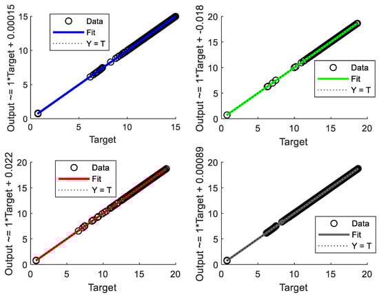
Figure 9.
Regression plots of the NN model.
4. Design of the Nonlinear Controller
In this section, a nonlinear control law is developed with the aim of driving the PV operating point towards the , which is treated as a reference. The control law is obtained through the backstepping concept, which is a principle based on Lyapunov recursive virtual construction. The controller will act on a boost converter which is responsible for adapting the PV plants to the load. In the spirit of nonlinear control, the full dynamical model (average state-space model) of the boost converter must be derived. It is obtained as seen in Equation (17) [28]. It is noted that stands for the converter’s state variables. Also, is the boost converter inductor current and is the output voltage. L and C are the inductance and capacitance of the boost converter. Note that the controller will be designed assuming a lossless system and operation in the continuous conduction mode.
The controller will, therefore, exploit (17) to stir the PV system to the desired reference . This reference voltage, which is the available approximated MPP voltage, is the system’s desired MPP reference. It is also the first state of the system; thus, for convenience, we can write the following:
According to Lyapunov’s theory, we can introduce the first error , which stands for the difference between the actual PV voltage reference voltage, written as
Taking the derivative of this error in the time domain results in the following:
From Equation (26), has been redefined as . That is, .
An integral action, is incorporated into the controller to take care of unmodeled uncertainties. Therefore, we can write the following:
Lyapunov functions are employed at this level to ascertain the controller’s stability. Consider to be a positive definite Lyapunov function, formulated according to Equation (23). According to Lyapunov’s law, settles to zero if the time-imitative of is negative definite
with .
The time-derivative of Equation (23) yields the following:
Inserting Equation (20) and the derivative of Equation (22) into (24) results in the following expression:
However, .
In this setting, Equation (25) yields the following:
The objective is to ascertain that is negative definite. Therefore, the first parameter, is integrated to allow the following:
By making subject of the formula in Equation (27), we derive the following:
Lyapunov’s theory warrants that we consider Equation (28) as a virtual reference. Furthermore, the difference from the virtual reference is introduced. We can consider that is the desired reference. Therefore, Equation (28) is rearranged as follows:
The difference is written as follows:
By rearranging Equation (30) and making the subject, we obtain the following:
If we insert Equation (31) into Equation (20), the following is yielded:
By combining Equations (29) and (32) the following is obtained:
By further simplification of Equation (33), we have the following expression:
Equation (24) is now written as follows:
By further simplification of Equation (35) with the expression t and , we obtain the following:
The time-derivatives of Equations (29) and (30) result in the following:
By adjusting Equation (38) with Equations (22) and (34), we obtain the following:
By inserting Equation (39) into Equation (37), we obtain the following:
The simplification of Equation (40) yields the following:
To ensure that the two error systems vanish to zero, a composite Lyapunov function is introduced, defined as
Taking the time derivative of Equation (42) yields the following:
By substituting Equation (36) into Equation (43), we obtain the following:
To ensure that Equation (44) is negative definite, the following expression is derived:
By combining Equations (44) and (45), the following expression is obtained:
Therefore, the Lyapunov law is confirmed. The updated law for the designed controller is finally derived through the expression of Equations (17), (41), and (45), as follows:
By rearranging the above expression, we obtain the final control law for the proposed integral backstepping controller as follows:
This is, therefore, the control law that ensures that the MPPT is stirred to the reference . The overall MPPT-PV system is implemented according to Figure 10. The system runs on a boost converter with primary parameters (L, , and . Although the controller was designed for a lossless ideal system, the implemented PV system considers practical components including the parasitic inductive resistance, and the capacitive resistances, and .
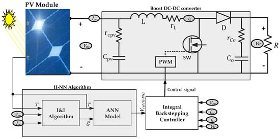
Figure 10.
Structure of the overall MPPT-PV system.
5. Results and Discussion
The overall PV system driven by the MPPT controller as seen in Figure 10 is implemented in MATLAB/Simulink. Several investigations are investigated to ascertain the performance of the proposed MPPT controller. The parameters of the implemented system are as follows: boost converter (), and integral backstepping controller (. The load is fixed at . The I&I gain (it remains this value except where specified). The parameters of the controller were determined through an iterative process of trial and observation, where various parameter values were tested and adjusted based on the system’s performance. By observing the system’s behavior under different conditions, we were able to refine the controller’s parameters to achieve the desired performance. This approach, while not based on a formal optimization process, allowed us to gradually improve the system’s stability, responsiveness, and overall efficiency through simulations and real-time adjustments.
The MSX-6 solar panel is used. Its model was experimentally confirmed in the previous sections. The response of the PV system at different values of G is shown in Figure 11, which shows that the convergence rate of the system increases with a decrease in G. This implies that at low irradiance, the PV system has a remarkably large settling time. This underscores the importance of defining the operating margin of the system. Therefore, for this study, the system is expected to be effectively functional in the irradiance range of and . Therefore, the operating area of the PV system must stay within the area shown in Figure 11 (right).
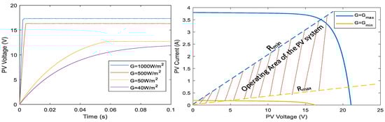
Figure 11.
(Left). Response of the PV system as a function of G (Right). The operating area of the studied system.
The first experiment performed on the system seeks to assess its performance under standard test conditions (G = ). It can be seen that the I&I effectively estimates the actual solar irradiance. At the gain of λ = , it converges in 12.8 ms (0.0128). We note that increasing the gain will increase the speed of convergence. Consequently, the PV voltage smoothly follows the II-NN reference voltage, which in turn aligns with the theoretical MPP voltage (see Figure 12, left). It can be seen that the system takes just about 3.3 ms to reach and stay at the theoretical MPP power of 59.94 W.
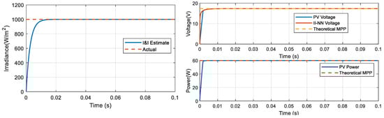
Figure 12.
Results of the system at STC. (Left) irradiance and its I&I estimate. (Right) voltage and power plots.
In the next experiment, the PV system is submitted to changing irradiance (increasing and decreasing pattern) as seen in Figure 13. It can be seen that the I&I smooth approximates the actual irradiance. There is good agreement between the estimated and actual irradiance. This highlights the robust performance of the estimator in the face of changing irradiance patterns. It can be seen in Figure 14 that the II-NN voltage aligns perfectly well with the theoretical MPP voltage. The capability of the proposed controller is demonstrated by the close tracking of the II-NN voltage. Consequently, there is smooth tracking of the MPP power. This highlights the effective maximum power point tracking. By comparing the areas under the PV power curve and those under the theoretical MPP power curve, the efficiency of the MPPT controller is obtained. It was found to be 99.84%, which is greater than that recently obtained in [37].
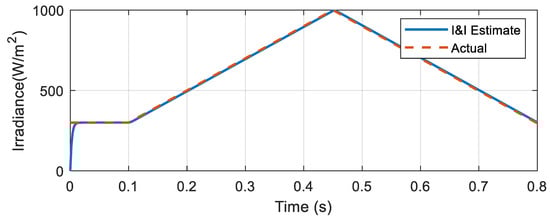
Figure 13.
Increasing and decreasing G and its I&I estimate.
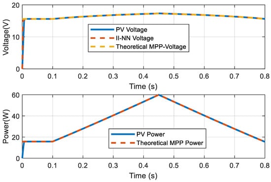
Figure 14.
Results of the PV system under changing climatic conditions. (Above) theoretical MPP voltage superimposes the II-NN voltage and the PV voltage. (Below) theoretical MPP power superimposes the PV power.
In the subsequent experiment, the MPPT system is evaluated for resilience against parametric uncertainty, also referred to as sensitivity testing. Conducting this sensitivity analysis is crucial for several reasons. In practice, photovoltaic (PV) systems are exposed to unpredictable uncertainties that can induce changes in the nominal values of model parameters. From a control perspective, this uncertainty manifests as a disturbance within the PV structure. Therefore, the controller must be robust enough to either maintain high immunity to such perturbations or demonstrate significant resilience to preserve the system’s efficiency.
Sensitivity testing involves subjecting all the components of the boost converter to parameter variations. Initially, the system operates with the following parameters: . At the time instant of 0.03 s, the parasitic components of the boost converter (input capacitance, inductor, and output capacitance) are increased to twice their initial values. Additionally, the boost input capacitance, output capacitance, and inductance are increased to 1.5 times their initial values. At 0.06 s, the boost inductance is further increased to five times its initial value, while its parasitic resistance is increased to three times its initial value. The relevance of conducting sensitivity analysis in PV-controlled systems lies in its ability to reveal the system’s behavior under uncertain conditions. This analysis helps in understanding how different parameters affect the overall performance and stability of the system. By simulating these variations, designers can conceive controllers that are not only effective under nominal conditions but also robust against real-world disturbances. More specifically, sensitivity analysis is essential in ensuring that PV systems are resilient and maintain optimal performance despite the inherent uncertainties in their operating environment. This approach provides valuable insights into the robustness of the MPPT system, guiding the improvements and adaptations necessary for reliable and efficient solar energy conversion.
The results of the sensitivity experiment are presented in Figure 15, Figure 16 and Figure 17. Firstly, it is notable that despite the two levels of parametric variations (at 0.03 s and 0.06 s), the estimated irradiance remains unaffected (see Figure 15). This indicates that the Immersion and Invariance (I&I) algorithm is robust against changes in plant parameters. This robustness is expected because the I&I algorithm depends solely on the PV current and voltage, and not on the parameters of the plant (boost converter). Evaluating the effect of these alterations on the overall system performance is crucial because the developed nonlinear controller relies on the plant’s nominal parameters. In scenario-A, which is the first instance of parametric variation (when input and output capacitances as well as inductance are increased to 1.5 times their nominal values, and boost inductance and parasitic components are doubled), the PV voltage experiences significant perturbation. It drifts from an MPP of 17.3 V to 11.26 V, representing an undershoot of approximately 35% (see Figure 16). Consequently, the power drops from the MPP value of 59.94 W to 42.41 W, resulting in an instantaneous power loss of about 17.53 W (see Figure 17). This demonstrates the impact of parametric alterations on the system. Despite this significant perturbation, the controller quickly restores the PV operating voltage and power to the MPP within just 3 microseconds (0.003 s). This rapid recovery showcases the controller’s robustness and resilience to substantial parametric variations.
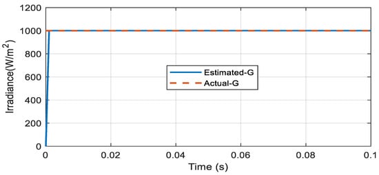
Figure 15.
Sensitivity test: estimated irradiance and its estimate under parametric variation.
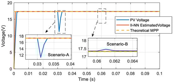
Figure 16.
Sensitivity test: theoretical MPP voltage, II-NN voltage, superimposed on the PV voltage under parametric variations.
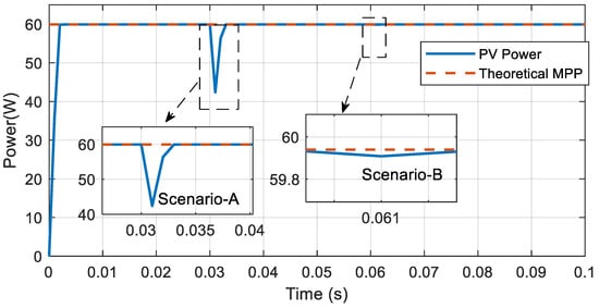
Figure 17.
Sensitivity test: theoretical MPP power, superimposed on the PV power under parametric variations.
In the second scenario (scenario-B), where the boost inductance is further increased to five times its initial value, and the parasitic inductance is tripled, the perturbation in PV voltage and power is almost negligible. The controller swiftly restores the system to the MPP, demonstrating that the controller maintains its efficiency even when the plant parameters significantly deviate from their nominal values. These results provide valuable insights into the robustness of the controller, highlighting its ability to maintain optimal performance and efficiency under varying conditions. This ensures that the PV system can operate reliably and effectively despite the inherent uncertainties in its operating environment.
Finally, the proposed system is closely monitored under real-time experimental conditions. Validating the MPPT algorithms with a real climatic measurement is of paramount importance for several compelling reasons. Given that solar irradiance and temperature vary significantly throughout the day due to changing weather conditions, shadows, and the sun’s angle, it is crucial to test MPPT algorithms under realistic scenarios that mirror these fluctuations. Using a day’s real climatic data provides a comprehensive and nuanced experimental evaluation of an MPPT algorithm’s performance. It allows for the observation of how the algorithm responds to transient conditions such as passing clouds, sudden temperature drops, or changes in wind speed, which are common in real-world environments but challenging to replicate accurately in laboratory settings. Real climatic measurements encompass a range of conditions that an MPPT system will encounter in practical applications, including variations in light intensity, temperature, and spectral changes, which directly affect the PV system’s voltage and current characteristics. Validating algorithms under these real-world conditions ensures that they can adapt quickly and effectively, maintaining optimal performance despite the inherent unpredictability of weather patterns. This validation is crucial for identifying and mitigating potential inefficiencies or shortcomings in the algorithm’s design, such as slow response times or instability under rapid changes in environmental conditions. By rigorously testing MPPT algorithms with actual climatic data, researchers and engineers can develop more robust and adaptive systems that are better equipped to maximize energy capture in diverse and dynamic conditions. Furthermore, this approach aids in the identification of potential long-term issues such as thermal degradation or component wear that may arise from fluctuating climatic conditions, ensuring that the system remains reliable over time. It also provides valuable insights into the operational limits and performance boundaries of the algorithms, helping to fine-tune them for enhanced resilience and efficiency. Additionally, validating with real climatic data can reveal specific geographic or seasonal patterns that could influence PV system performance, enabling more tailored and effective solutions for different environments. Ultimately, this validation process is essential for advancing the field of renewable energy by ensuring that MPPT algorithms can deliver consistent and reliable performance in real-world conditions, thereby enhancing the overall sustainability and efficiency of solar energy systems and contributing to a more reliable and sustainable energy future. To this end, an experimental setup was constructed to record a day’s real climatic condition on the solar panel. The collection ran from 6:00 A.M. to 6:00 P.M. The acquired climatic conditions are presented in Figure 18. These experimental conditions are crucial for validating the performance of the proposed intelligent system. The acquired experimental G and T are injected into the experimentally validated PV model to obtain the experimental MPP voltage. This voltage can, thus, be compared with the II-NN estimated voltage. To quantify the performance of the II-NN, the mean absolute error (MAE) and mean absolute percentage error (MAPE) are employed as defined in (49) and (50).
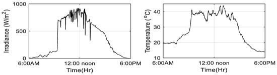
Figure 18.
Experimental climatic conditions. (Left) irradiance. (Right) temperature.
In order to accurately assess the performance of the II-NN (Iterative-Interpolation Neural Network) algorithm, we have injected the experimental conditions to obtain the voltage estimates. Figure 19 illustrates the plot comparing the estimated voltages from the II-NN model with the actual experimental voltages recorded throughout the day. It is evident from the figure that there is a high degree of correlation between the two curves, demonstrating a remarkable consistency in performance across varying conditions. The MAE and MAPE are recorded to be just 0.0183 V and 0.3916%. This outstanding correspondence not only highlights the efficacy of the trained neural network model but also underscores the robustness and adaptability of the II-NN algorithm in real-world scenarios. The ability of the II-NN to closely match the actual voltage measurements validates its effectiveness in accurately modeling and predicting system behavior under dynamic and fluctuating conditions. This robust performance is a testament to the algorithm’s sophisticated design and its capability to handle complex, nonlinear relationships within the experimental data. The II-NN’s resilience and precision in reflecting real-world voltage fluctuations signify its potential for reliable application in various practical settings, further proving its utility and dependability. Finally, the overall MPPT system is evaluated under these experimental conditions to appraise the effectiveness of the MPPT controller in tracking the experimental MPP voltage. Figure 20 displays a graph of the PV system’s experimental MPP voltage superimposed on the PV voltage under MPPT operation. The data reveal that the PV voltage driven by the MPPT controller closely follows the experimental MPP voltage throughout most of the day, demonstrating the controller’s proficiency in adapting to varying conditions and maximizing power extraction. However, it is notable that during the early morning hours, the MPPT controller’s performance is less effective. This outcome is anticipated and can be attributed to the low irradiance levels in this period, which fall below the minimum operational threshold of 50 W/m2. Such conditions pose significant constraints for the MPPT system, which cannot efficiently track the MPP in these low-light scenarios. This observation underscores the challenges faced by MPPT controllers under real-world conditions, as opposed to idealized, simulated environments. The variability and unpredictability of natural sunlight introduce complexities that are difficult to replicate in simulations, highlighting the necessity of rigorous experimental validation. These findings not only validate the overall effectiveness of the MPPT system but also emphasize the importance of considering environmental constraints that may impact performance in practical applications.
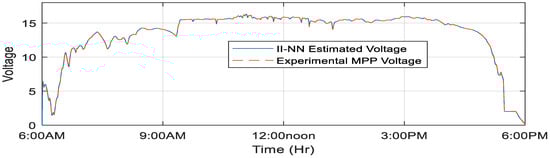
Figure 19.
Plot of experimental MPP voltage superimposes the II-NN estimate.
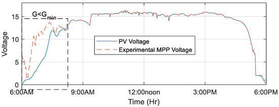
Figure 20.
Plot of experimental MPP voltage superimposes PV voltage under MPPT operation.
Finally, the performance of the proposed MPPT scheme is compared under experimental conditions against the P&O, INC, and the algorithms recently proposed in [28,30,37].
The power harvested by the PV system using different MPPT algorithms was recorded and compared with the proposed algorithm. Figure 21, Figure 22, Figure 23, Figure 24 and Figure 25 illustrate the comparative performance of the proposed MPPT algorithm against the P&O, INC, and other state-of-the-art algorithms found in the literature. The graphs show that around midday, the INC, P&O, and alternate algorithms achieve performance comparable to that of the proposed algorithm, all effectively tracking the experimental MPP. However, during the early morning hours and late in the evening (when irradiance has a lower magnitude and changing slowly), the proposed algorithm significantly outperforms the conventional and alternative algorithms. This indicates that these traditional algorithms as well as the state-of-the-art methods struggle to operate effectively under extreme low-light conditions. Although the proposed algorithm does not perfectly track the MPP under these challenging conditions, it demonstrates commendable performance, achieving a remarkable efficiency of 99.83%. These experimental results highlight the superiority and robustness of the proposed MPPT algorithm. It not only outperforms conventional methods but also surpasses state-of-the-art techniques in dealing with varying irradiance levels. The proposed algorithm’s ability to maintain high efficiency under suboptimal conditions validates its efficacy and potential for broader application in real-world PV systems, where environmental conditions can fluctuate unpredictably. This finding underscores the importance of developing more adaptive and resilient MPPT algorithms capable of optimizing power output across a wide range of operating scenarios.
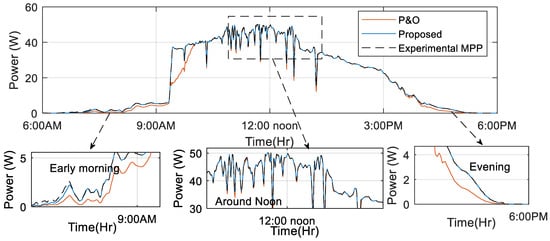
Figure 21.
Performance comparison of the proposed MPPT with the P&O under experimental conditions.
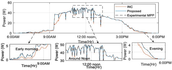
Figure 22.
Performance comparison of the proposed MPPT with the INC under experimental conditions.
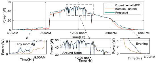
Figure 23.
Performance comparison of the proposed MPPT with that proposed in [30] under experimental conditions.
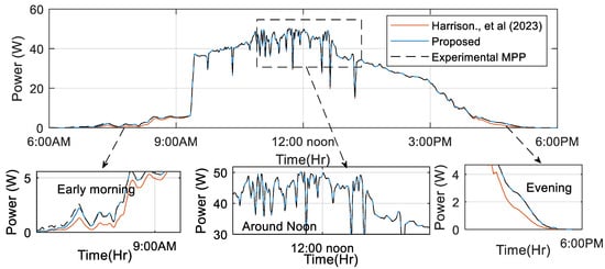
Figure 24.
Performance comparison of the proposed MPPT with that of [28] under experimental conditions.
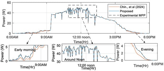
Figure 25.
Performance comparison of the proposed MPPT with that of [37] under experimental conditions.
To thoroughly confirm the practical effectiveness of the proposed control strategies, an experimental hardware test was designed and executed. These tests were not only crucial but also integral in validating the accuracy and reliability of the results that had been obtained through extensive simulations. Given the complexity and the high stakes involved in deploying such control strategies in real-world applications, it was imperative to go beyond mere theoretical validations. Hence, the experimental approach adopted was both robust and rigorous, designed to thoroughly assess the performance of the developed MPPT controller under complex conditions. The core of this validation process centered around a sophisticated experimental setup as depicted in Figure 26.

Figure 26.
Experimental test bench for the proposed system.
This setup was not simply a laboratory arrangement but a carefully engineered platform specifically designed to test the practical application of the control strategies in question. It served as the backbone for the experimental validation process, offering a controlled environment in which the performance of both the boost converter and its associated control mechanisms could be evaluated in real time. The boost converter, being a critical component in PV systems, required precise control to ensure optimal performance, particularly in varying environmental conditions. Therefore, the setup included the advanced control systems, notably the II&NN algorithm and the integral backstepping controller. These control systems were integral to the overall strategy, providing a means to optimize the efficiency and reliability of the boost converter. The primary objective of this experimental setup was to facilitate a closed-loop evaluation of the entire control system. This approach allowed for real-time monitoring and adjustment, ensuring that the system’s performance could be continuously optimized during the testing phase. The closed-loop system was crucial in mimicking the dynamic conditions that the control strategies would encounter in actual deployment, thereby providing a realistic and practical assessment of their effectiveness. The experimental setup, therefore, played a pivotal role in bridging the gap between theoretical simulation and practical implementation, providing a platform for rigorous testing and validation. A key feature of this experimental setup was its implementation as a “Processor-in-the-Loop” (PIL) system. The PIL setup is a sophisticated arrangement that allows control algorithms, which were initially developed and tested in a simulated environment, to be executed on an actual hardware processor. This transition from simulation to hardware is critical, as it ensures that the algorithms perform as expected under real-world conditions. In the context of this experiment, the PIL setup utilized an Arduino Uno board, with the Arduino Due specifically tasked with executing the control law in real time. This real-time execution was essential for providing a realistic and practical test of the PV system’s functionality, ensuring that the control strategies could be applied effectively in practical scenarios.
The process of transitioning from simulation to hardware involved several critical steps. Initially, the control system was developed and tested in a simulated environment using Simulink, a powerful tool for modeling, simulating, and analyzing dynamic systems. The use of Simulink allowed for a detailed and accurate simulation of the control strategies, providing a solid foundation for their subsequent implementation. Once the simulation results were validated, the control algorithms were converted into executable C/C++ code through advanced code generation tools. This step was crucial in ensuring that the algorithms could be efficiently executed on the processor hardware, maintaining the same level of precision and efficiency that was achieved in the simulation. The PIL setup offered several significant advantages, making it an indispensable tool in the validation process. One of the primary benefits was its ability to test the proposed solutions. This capability was vital in ensuring that the control strategies were robust and adaptable, able to maintain optimal performance across a range of scenarios. Furthermore, the PIL setup provided an opportunity to identify any potential discrepancies or areas for improvement that might not have been evident during the simulation phase. By testing the algorithms on a physical hardware processor, the setup could uncover issues related to hardware–software interaction, timing, and real-time performance that could impact the overall reliability of the PVE system.
It should be noted that the Simulink software (https://www.mathworks.com/products/simulink.html accessed on 3 September 2024) allows only discrete operation in PIL experiments. Therefore, the integral backstepping controller is discretized in implementations. Also, the integral in the II algorithm is implemented in a discrete form. Additionally, for seamless operations, a data conversion block is introduced to ensure that the control system runs on single data precision to support accurate data transfer with the Arduino Uno board.
In the context of our experiment, we made a deliberate choice to validate the most challenging scenarios from our simulations. Among these, the scenario depicted in Figure 16, which involves heavy parametric uncertainty, was selected as the primary focus of our validation efforts. This specific scenario presented a significant test for the robustness and accuracy of our proposed control solutions given the complexity and unpredictability associated with parametric uncertainty. By choosing this demanding case, we aimed to thoroughly evaluate the effectiveness of our algorithms under conditions that closely mimic the unpredictable nature of real-world applications. The results of our experiment, particularly the plots of estimated irradiance, are presented in Figure 27. These plots include the data derived from both the simulations and the physical experiment. A careful comparison of these results reveals a striking alignment between the estimated irradiance from the simulations and that obtained from the experimental setup. This strong correlation is a critical indicator that not only confirms the accuracy of our simulation results but also provides compelling evidence of the practical efficacy of the algorithm we have developed. The ability of the experimental data to mirror the simulation outcomes so closely, especially in the context of irradiance tracking, underscores the reliability of the control strategies under investigation.
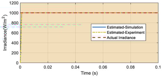
Figure 27.
Experimental results: plots of estimated G from simulation and experiment with superimposed actual G.
Moreover, in addition to evaluating irradiance, we also conducted a thorough examination of the PV voltage and power outputs, both in the simulations and the experiment, to ensure their consistency and alignment. Figure 28 and Figure 29 present the comparative analysis of PV voltage and power derived from both the simulations and the experimental data. These figures clearly demonstrate a strong agreement between the simulated and experimental values, with both closely tracking the MPP as previously reported. This strong alignment, even under the conditions of heavy parametric uncertainty, particularly noticeable at specific time intervals such as 0.03s and 0.06s, further reinforces the reliability and robustness of the proposed control strategies.
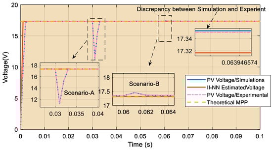
Figure 28.
Experimental results of voltage: plot of II-NN estimate, PV (simulations), PV (experiment), and theoretical MPP.
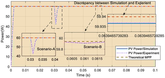
Figure 29.
Experimental results of power: plot of II-NN estimate, PV (simulations), PV (experiment), and theoretical MPP.
However, despite the overall strong agreement between the simulation and experimental results, a more detailed observation reveals a very slight discrepancy between the two, particularly in the voltage and power outputs. This minor difference, while negligible, is noteworthy as it highlights the inherent nonlinearity that distinguishes the simulation environment from the hardware processor-driven setup. The nonlinearity gap, which is a common occurrence when transitioning from a simulated to a processor environment, may account for these small discrepancies. It is important to recognize that while simulations provide a controlled and idealized environment, hardware processor experiments introduce variables and complexities that are often difficult to fully replicate in a simulated context. In light of these findings, it is sufficient to conclude that the proposed control solutions are not only theoretically sound but also practically viable. The close alignment between the simulation and experimental results, particularly under challenging conditions of heavy parametric uncertainty, validates the robustness of our control algorithms. The negligible discrepancies observed do not detract from the overall effectiveness of the solution but rather provide valuable insights into areas where further refinement and optimization could be applied to bridge the gap between simulation and real-world performance. Ultimately, these results underscore the practical applicability of our control strategies in real-world scenarios, providing a strong foundation for their deployment in photovoltaic energy systems and other relevant applications.
The implementation of the proposed MPPT control scheme, while demonstrating high efficiency and robustness in simulations, presented several challenges during practical deployment, particularly in real-time systems. These challenges can be categorized into the following areas:
- PIL Experimentation and Hardware Integration: One of the primary challenges encountered during implementation was the integration of the control algorithm into the real-time system using the PIL setup. The transition from simulation to hardware posed several difficulties. In the simulation environment, the control algorithms could be executed with precise timing and ideal conditions. However, when applied to a hardware platform such as the Arduino Uno, real-time constraints and hardware limitations became apparent. These included delays in data processing, the need to discretize continuous control algorithms for execution on digital processors, and ensuring precise communication between the hardware and software components. These factors led to minor discrepancies between the simulation results and real-world performance, primarily due to the nonlinearity introduced by hardware execution.
- Controller Tuning and Stability Under Parametric Uncertainty: Another challenge was the tuning of the nonlinear controller, which needed to be robust against the parametric uncertainties introduced by variations in the system’s components (e.g., inductance and capacitance in the boost converter). Although the controller showed resilience to such variations in the simulations, the real-world implementation revealed that small perturbations in the system parameters could still lead to transient instability or slower convergence to the MPP. Fine-tuning the controller gains was necessary to improve the system’s responsiveness, but this introduced a trade-off between stability and dynamic response, particularly under rapidly changing environmental conditions.
- Scaling and Applicability Under Partial Shading Conditions: While the proposed control system performed well under uniform irradiance conditions, it struggled under partial shading scenarios. The current model does not account for the multiple power peaks that occur under partial shading, which significantly reduces the efficiency of MPP tracking. Implementing more sophisticated algorithms that can handle partial shading (e.g., metaheuristic approaches or enhanced P&O methods) could alleviate this issue, but this would come at the cost of increased complexity and processing requirements. As such, one of the limitations of the current system is its reduced applicability in environments prone to partial shading.
6. Conclusions
The problem addressed in this paper revolves around the inherent challenges associated with optimizing the performance of standalone PV systems, specifically in the context of MPPT under varying real-world climatic conditions. Contemporary MPPT algorithms often rely heavily on direct irradiance measurements, which are not only costly but also add significant complexity to the system. Furthermore, conventional methods and conventional-inherited methods struggle to maintain efficiency under rapidly changing environmental conditions and extreme scenarios, leading to suboptimal energy capture and inefficiencies in real-world applications. To tackle these issues, the paper proposed a novel intelligent control scheme that integrates a nonlinear estimator, termed the Immersion and Invariance Neural Network (II-NN) algorithm, which effectively estimates the MPP voltage without relying on direct irradiance measurements. This approach is complemented by a robust nonlinear controller designed using integral backstepping, which enhances the system’s ability to handle nonlinearities and unmodeled uncertainties in PV operations. The II-NN algorithm leverages the real-time measurements of PV current and voltage to estimate the incident solar irradiance, which is then used by a neural network model to ascertain the optimal MPP voltage. The proposed system’s efficacy was rigorously evaluated under real climatic conditions collected over a full day, providing a realistic and comprehensive dataset for performance validation. The experimental results highlighted a mean absolute error of just 0.0183 V and a mean absolute percentage error of 0.3913%, with the system achieving an overall MPPT efficiency of 99.84%. These outcomes not only underscore the robustness and adaptability of the proposed II-NN algorithm but also demonstrate its superior performance compared to state-of-the-art methods, particularly in low-light conditions where traditional algorithms fail to perform effectively. The proposed MPPT system consistently tracked the experimental MPP voltage throughout the day, except during early morning hours when irradiance levels were below the minimum operational threshold, which is expected and highlights the realistic operational constraints faced by MPPT systems. The comparison with conventional algorithms revealed that while the proposed system maintains a high degree of performance even under challenging conditions, traditional methods like P&O and INC falter, particularly during extreme climatic variations. The findings from this study validate the proposed intelligent MPPT control scheme as a highly effective and robust solution for optimizing PV system performance, offering a significant advancement over the existing methodologies by eliminating the need for costly irradiance sensors and ensuring reliable operation across a diverse range of environmental conditions. This work contributes significantly to the field of control of renewable energy by presenting a cost-effective, efficient, and adaptable MPPT solution, thus enhancing the practical viability and sustainability of solar energy systems. However, the main shortcoming of this work is its limitation to uniformly operating PV systems. The II&NN was developed for uniformly operating PV systems. In its current structure, it cannot handle the highly intricate conditions possessed by partial shading. It would, therefore, be interesting to pursue further development of the II&NN in order to meet the demands of a partially shaded PV system. Additionally, the aging process of PV modules can potentially influence both the performance of the proposed model and the operation of the MPPT control unit. Over time, the degradation of PV cells may affect parameters such as the current–voltage characteristics, which are key inputs to the control system. While we have not yet experimentally verified the impact of module aging on our specific model, it is indeed an important area for future research. Incorporating the effects of aging into the model would provide a more comprehensive understanding of the system’s long-term performance and robustness.
Author Contributions
Conceptualization, J.S. and J.F.; methodology, J.S.; software, J.S.; validation, J.S. and J.F.; formal analysis, J.S. and J. F; investigation, J.S.; resources, J.S. and J.F.; data curation, J.S. and J.F.; writing—original draft preparation, J.F.; writing—review and editing, J.S. and J.F.; visualization, J.S. and J.F.; supervision, J.F.; project administration, J.F.; funding acquisition, J.S. and J.F. All authors have read and agreed to the published version of the manuscript.
Funding
This research received no external funding.
Data Availability Statement
All the data used in this study are included within the paper.
Conflicts of Interest
The authors declare no conflicts of interest.
Nomenclature, Subscripts and Abbreviations
| Nomenclature | Subscripts | ||
| Fobj | Objective function | ref | Reference standard test conditions |
| Ipv, Vpv | PV current and PV voltage | Abbreviations | |
| Rs, Rp | Series and resistance | MPPT | Maximum power point tracking |
| G, T | Irradiance (W/m2), temperature (°C) | MPP | Maximum power point |
| Ns | Number of series modules | INC | Incremental conductance MPPT |
| Imppt, Vmppt, Pmppt | MPP current, voltage, and power at MPPT | P&O | Perturb and observe MPPT |
| Io | Reverse saturation current | NN | Neural network |
| Ns | Number of cells in series | PV | Photovoltaic |
| Diode ideality factor | II | Immersion and Invariance | |
| Iph | Photocurrent | II-NN | Immersion Invariance Neural Network |
| Estimate of irradiance | I-V | Current–voltage | |
| Pmode, Vmodel, Imodel | Model power, voltage, and current at MPP | PWM | Pulse Width Modulation |
| Minimum operating irradiance | ANN | Artificial neural network | |
| Maximum operating irradiance | FSCC | fractional short circuit current | |
| Parasitic components of converter | FOCV | fractional open circuit voltage | |
| Vmpp | MPP voltage | PID | Proportional Integral Derivative |
| L | Boost inductance | PSO | Particle Swarm Optimization |
| Cpv | Boost input capacitance | STC | Standard test condition |
| Co | Boost output capacitance | ACO | Ant Colony Optimization |
| R | Load | MAE | Mean absolute error |
| Control duty cycle | MAPE | Mean absolute percentage error | |
| Parameters of controller | STC | Standard test condition | |
| Gain of II | PIL | Processor-in-the-loop | |
| System state variables | |||
| wi | Parameters of the panel used by II Reference voltage generated by II-NN | ||
References
- Sawle, Y.; Gupta, S.C.; Bohre, A.K. Socio-Techno-Economic Design of Hybrid Renewable Energy System Using Optimization Techniques. Renew. Energy 2018, 119, 459–472. [Google Scholar] [CrossRef]
- Olabi, A.G.; Mahmoud, M.; Soudan, B.; Wilberforce, T.; Ramadan, M. Geothermal Based Hybrid Energy Systems, toward Eco-Friendly Energy Approaches. Renew. Energy 2020, 147, 2003–2012. [Google Scholar] [CrossRef]
- Yavuzdeger, A.; Ekinci, F. Performance Assessment of a Novel Eco-Friendly Solar Panel Mounted Hybrid Rotating Energy System with Renewable Energy Applications. IETE J. Res. 2023, 69, 6557–6572. [Google Scholar] [CrossRef]
- Green, M.A.; Dunlop, E.D.; Hohl-Ebinger, J.; Yoshita, M.; Kopidakis, N.; Hao, X. Solar Cell Efficiency Tables (Version 56). Prog. Photovolt. Res. Appl. 2020, 28, 629–638. [Google Scholar] [CrossRef]
- Green, M.A.; Ho-Baillie, A.; Snaith, H.J. The Emergence of Perovskite Solar Cells. Nat. Photonics 2014, 8, 506–514. [Google Scholar] [CrossRef]
- Tian, H.; Mancilla-David, F.; Ellis, K.; Muljadi, E.; Jenkins, P. A Cell-to-Module-to-Array Detailed Model for Photovoltaic Panels. Sol. Energy 2012, 86, 2695–2706. [Google Scholar] [CrossRef]
- Marzband, M.; Sumper, A.; Ruiz-Álvarez, A.; Domínguez-García, J.L.; Tomoiagă, B. Experimental Evaluation of a Real Time Energy Management System for Stand-Alone Microgrids in Day-Ahead Markets. Appl. Energy 2013, 106, 365–376. [Google Scholar] [CrossRef]
- Micheli, D.; Alessandrini, S.; Radu, R.; Casula, I. Analysis of the Outdoor Performance and Efficiency of Two Grid Connected Photovoltaic Systems in Northern Italy. Energy Convers. Manag. 2014, 80, 436–445. [Google Scholar] [CrossRef]
- Nguimfack-Ndongmo, J.d.D.; Kenné, G.; Kuate-Fochie, R.; Tchouani Njomo, A.F.; Mbaka Nfah, E. Adaptive Neuro-Synergetic Control Technique for SEPIC Converter in PV Systems. Int. J. Dyn. Control 2022, 10, 203–216. [Google Scholar] [CrossRef]
- Flanclair, A.; Njomo, T.; Kuate-fochie, R.; Douanla, R.M.; Sonfack, L.L.; Kenne, G. Climatic Sensorless Maximum Power Point Tracking Based on Adaptive Neuro- Extremum Seeking Control Technique in PV Generation Systems. Energy Syst. 2023, 14, 1–22. [Google Scholar] [CrossRef]
- Salau, A.O.; Alitasb, G.K. MPPT Efficiency Enhancement of a Grid Connected Solar PV System Using Finite Control Set Model Predictive Controller. Heliyon 2024, 10, e27663. [Google Scholar] [CrossRef] [PubMed]
- Tchouani Njomo, A.F.; Kenne, G.; Douanla, R.M.; Sonfack, L.L. A Modified ESC Algorithm for MPPT Applied to a Photovoltaic System under Varying Environmental Conditions. Int. J. Photoenergy 2020, 2020, 1–15. [Google Scholar] [CrossRef]
- Kamarzaman, N.A.; Tan, C.W. A Comprehensive Review of Maximum Power Point Tracking Algorithms for Photovoltaic Systems. Renew. Sustain. Energy Rev. 2014, 37, 585–598. [Google Scholar] [CrossRef]
- Katche, M.L.; Makokha, A.B.; Zachary, S.O.; Adaramola, M.S. A Comprehensive Review of Maximum Power Point Tracking (MPPT) Techniques Used in Solar PV Systems. Energies 2023, 16, 2206. [Google Scholar] [CrossRef]
- Senthilkumar, S.; Mohan, V.; Deepa, R.; Nuthal Srinivasan, M.; Senthil Kumar, T.; Thanikanti, S.B.; Prathap, N. A review on mppt algorithms for solar pv systems. Int. J. Res.-GRANTHAALAYAH 2023, 11, 25–64. [Google Scholar] [CrossRef]
- Esram, T.; Chapman, P.L. Comparison of Photovoltaic Array Maximum Power Point Tracking Techniques. IEEE Trans. Energy Convers. 2007, 22, 439–449. [Google Scholar] [CrossRef]
- Paz, F.; Ordonez, M. Zero-Oscillation Adaptive-Step Solar Maximum Power Point Tracking for Rapid Irradiance Tracking and Steady-State Losses Minimization. In Proceedings of the 2013 4th IEEE International Symposium on Power Electronics for Distributed Generation Systems (PEDG), Rogers, AR, USA, 8–11 July 2013. [Google Scholar] [CrossRef]
- Tey, K.S.; Mekhilef, S. Modified Incremental Conductance Algorithm for Photovoltaic System Under Partial Shading Conditions and Load Variation. IEEE Trans. Ind. Electron. 2014, 61, 5384–5392. [Google Scholar] [CrossRef]
- Mahmod Mohammad, A.N.; Mohd Radzi, M.A.; Azis, N.; Shafie, S.; Atiqi Mohd Zainuri, M.A. An Enhanced Adaptive Perturb and Observe Technique for Efficient Maximum Power Point Tracking Under Partial Shading Conditions. Appl. Sci. 2020, 10, 3912. [Google Scholar] [CrossRef]
- Jain, S.; Member, S.; Agarwal, V.; Member, S. A New Algorithm for Rapid Tracking of Approximate Maximum Power Point in Photovoltaic Systems. IEEE Power Electron. Lett. 2004, 2, 16–19. [Google Scholar] [CrossRef]
- Li, X.; Wen, H.; Zhao, C. Improved Beta Parameter Based MPPT Method in Photovoltaic System. In Proceedings of the 2015 9th International Conference on Power Electronics and ECCE Asia (ICPE-ECCE Asia), Seoul, Republic of Korea, 1–5 June 2015; pp. 1405–1412. [Google Scholar]
- Li, X.; Wen, H.; Hu, Y.; Jiang, L.; Xiao, W. Modified Beta Algorithm for GMPPT and Partial Shading Detection in Photovoltaic Systems. IEEE Trans. Power Electron. 2018, 33, 2172–2186. [Google Scholar] [CrossRef]
- Belghiti, H.; Kandoussi, K.; Chellakhi, A.; Mchaouar, Y.; El Otmani, R.; Sadek, E.M. Performance Optimization of Photovoltaic System under Real Climatic Conditions Using a Novel MPPT Approach. Energy Sources Part A Recover. Util. Environ. Eff. 2024, 46, 2474–2492. [Google Scholar] [CrossRef]
- Harrison, A.; Alombah, N.H.; de Dieu Nguimfack Ndongmo, J. Solar Irradiance Estimation and Optimum Power Region Localization in PV Energy Systems under Partial Shaded Condition. Heliyon 2023, 9, e18434. [Google Scholar] [CrossRef] [PubMed]
- Korany, E.; Yousri, D.; Attia, H.A.; Zobaa, A.F.; Allam, D. A Novel Optimized Dynamic Fractional-Order MPPT Controller Using Hunter Pray Optimizer for Alleviating the Tracking Oscillation with Changing Environmental Conditions. Energy Rep. 2023, 10, 1819–1832. [Google Scholar] [CrossRef]
- Iftikhar, R.; Ahmad, I.; Arsalan, M.; Naz, N.; Ali, N.; Armghan, H. MPPT for Photovoltaic System Using Nonlinear Controller. Int. J. Photoenergy 2018, 2018, 1–11. [Google Scholar] [CrossRef]
- Arsalan, M.; Iftikhar, R.; Ahmad, I.; Hasan, A.; Sabahat, K.; Javeria, A. MPPT for Photovoltaic System Using Nonlinear Backstepping Controller with Integral Action. Sol. Energy 2018, 170, 192–200. [Google Scholar] [CrossRef]
- Harrison, A.; Alombah, N.H.; de Dieu Nguimfack Ndongmo, J. A New Hybrid MPPT Based on Incremental Conductance-Integral Backstepping Controller Applied to a PV System under Fast-Changing Operating Conditions. Int. J. Photoenergy 2023, 2023, 1–17. [Google Scholar] [CrossRef]
- Chellakhi, A.; Beid, S.E.; Abouelmahjoub, Y. Implementation of a Novel MPPT Tactic for PV System Applications on MATLAB/Simulink and Proteus-Based Arduino Board Environments. Int. J. Photoenergy 2021, 2021, 6657627. [Google Scholar] [CrossRef]
- Kamran, M.; Mudassar, M.; Fazal, M.R.; Asghar, M.U.; Bilal, M.; Asghar, R. Implementation of Improved Perturb & Observe MPPT Technique with Confined Search Space for Standalone Photovoltaic System. J. King Saud Univ.-Eng. Sci. 2020, 32, 432–441. [Google Scholar] [CrossRef]
- Harrison, A.; Nfah, E.M.; de Dieu Nguimfack Ndongmo, J.; Alombah, N.H. An Enhanced P&O MPPT Algorithm for PV Systems with Fast Dynamic and Steady-State Response under Real Irradiance and Temperature Conditions. Int. J. Photoenergy 2022, 2022, 1–21. [Google Scholar] [CrossRef]
- Harrison, A.; Feudjio, C.; Raoul Fotso Mbobda, C.; Alombah, N.H. A New Framework for Improving MPPT Algorithms through Search Space Reduction. Results Eng. 2024, 22, 101998. [Google Scholar] [CrossRef]
- Calvinho, G.; Pombo, J.; Mariano, S.; Rosario Calado, M. do Design and Implementation of MPPT System Based on PSO Algorithm. In Proceedings of the 2018 International Conference on Intelligent Systems (IS), Funchal, Portugal, 25–27 September 2018; pp. 733–738. [Google Scholar]
- Hadji, S.; Gaubert, J.-P.; Krim, F. Real-Time Genetic Algorithms-Based MPPT: Study and Comparison (Theoretical an Experimental) with Conventional Methods. Energies 2018, 11, 459. [Google Scholar] [CrossRef]
- Titri, S.; Larbes, C.; Toumi, K.Y.; Benatchba, K. A New MPPT Controller Based on the Ant Colony Optimization Algorithm for Photovoltaic Systems under Partial Shading Conditions. Appl. Soft Comput. 2017, 58, 465–479. [Google Scholar] [CrossRef]
- Firmanza, A.P.; Habibi, M.N.; Windarko, N.A.; Yanaratri, D.S. Differential Evolution-Based MPPT with Dual Mutation for PV Array under Partial Shading Condition. In Proceedings of the 2020 10th Electrical Power, Electronics, Communications, Controls and Informatics Seminar (EECCIS), Malang, Indonesia, 26 August 2020; pp. 198–203. [Google Scholar]
- Chen, T.; Harrison, A.; Alombah, N.H.; Aurangzeb, M.; Iqbal, S.; Mahmoud, H.A. A Simplified Control Algorithm for Efficient and Robust Tracking of the Maximum Power Point in PV Systems. Control Eng. Pract. 2024, 148, 105945. [Google Scholar] [CrossRef]
- Xiong, G.; Zhang, J.; Shi, D.; He, Y. Parameter Extraction of Solar Photovoltaic Models Using an Improved Whale Optimization Algorithm. Energy Convers. Manag. 2018, 174, 388–405. [Google Scholar] [CrossRef]
- Qais, M.H.; Hasanien, H.M.; Alghuwainem, S. Identification of Electrical Parameters for Three-Diode Photovoltaic Model Using Analytical and Sunflower Optimization Algorithm. Appl. Energy 2019, 250, 109–117. [Google Scholar] [CrossRef]
- Patel, S. The Single Diode Model of I-V and P-V Characteristics Using the Lambert W Function. J. Innov. Res. Sci. Eng. Technol. 2016, 5, 7034–7039. [Google Scholar] [CrossRef]
- Astolfi, A.; Ortega, R. Immersion and Invariance: A New Tool for Stabilization and Adaptive Control of Nonlinear Systems. IEEE Trans. Automat. Contr. 2003, 48, 590–606. [Google Scholar] [CrossRef]
- Liu, X.; Ortega, R.; Su, H.; Chu, J. Immersion and Invariance Adaptive Control of Nonlinearly Parameterized Nonlinear Systems. In Proceedings of the 2009 American Control Conference, St. Louis, MO, USA, 10–12 June 2009; pp. 1268–1273. [Google Scholar]
- Henry, N.; Harrison, A.; Kamel, S.; Bertrand, H.; Aurangzeb, M. Development of an Efficient and Rapid Computational Solar Photovoltaic Emulator Utilizing an Explicit PV Model. Sol. Energy 2024, 271, 112426. [Google Scholar] [CrossRef]
- Galushkin, A.I. Neural Network Theory; Springer Science & Business Media: Berlin/Heidelberg, Germany, 2007; pp. 1–396. [Google Scholar] [CrossRef]
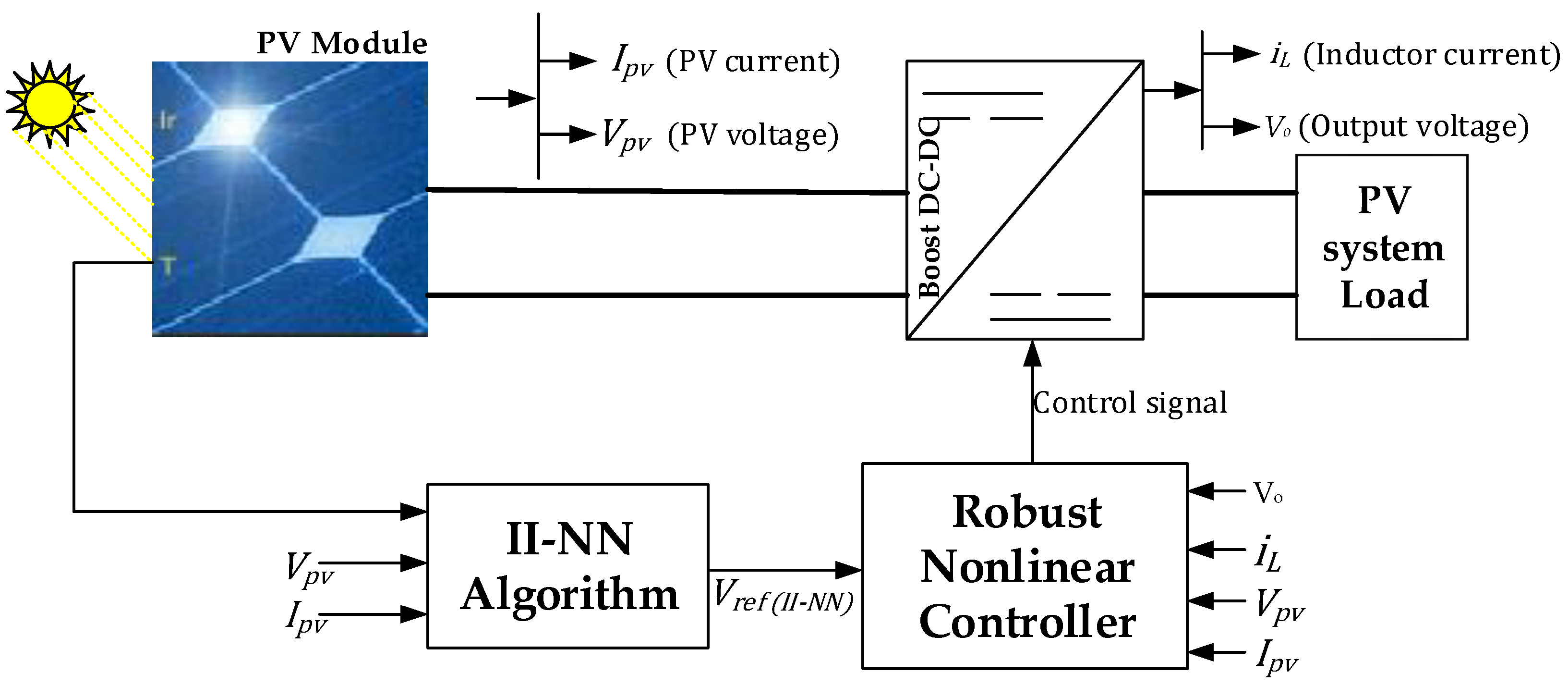
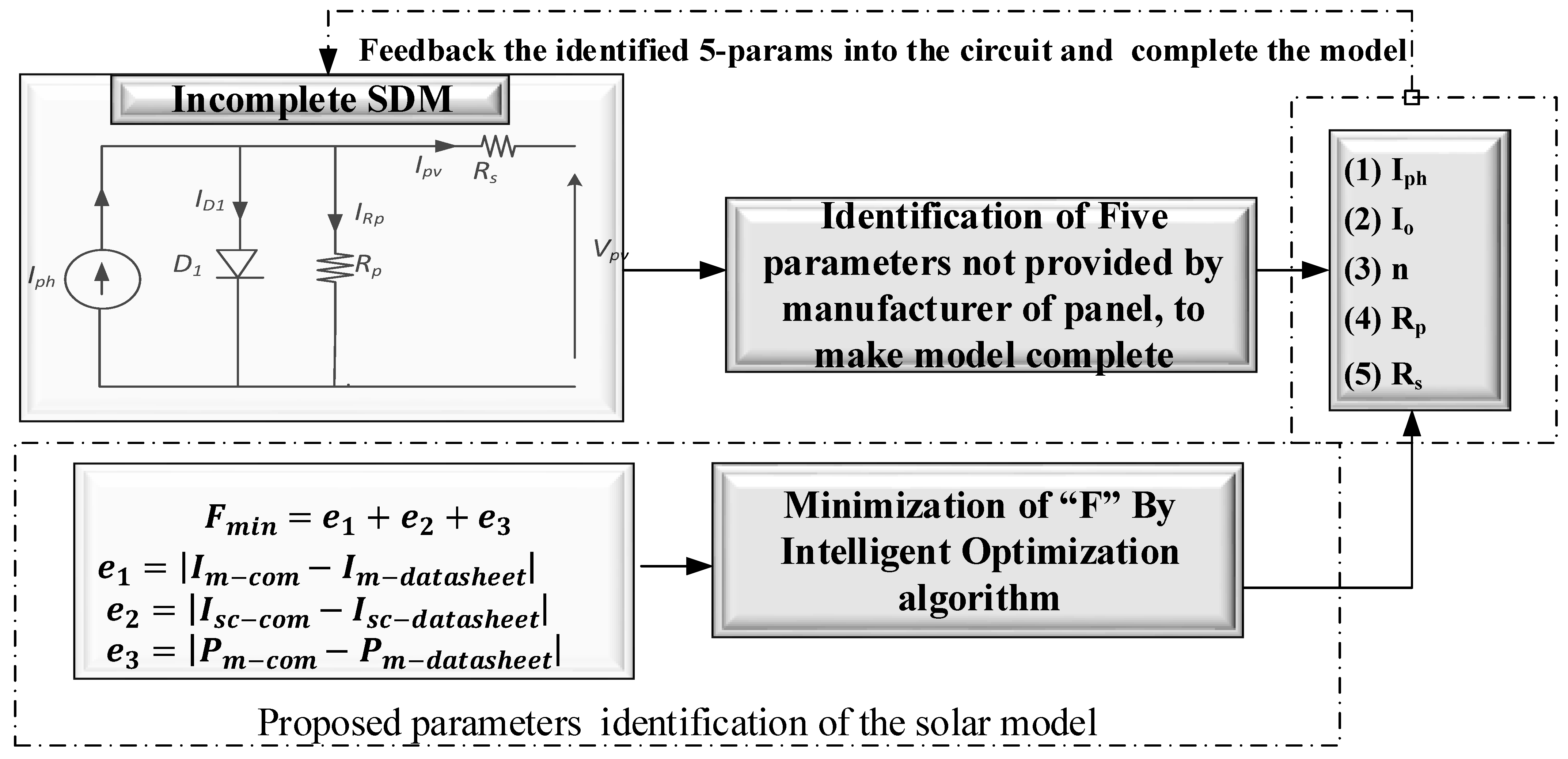
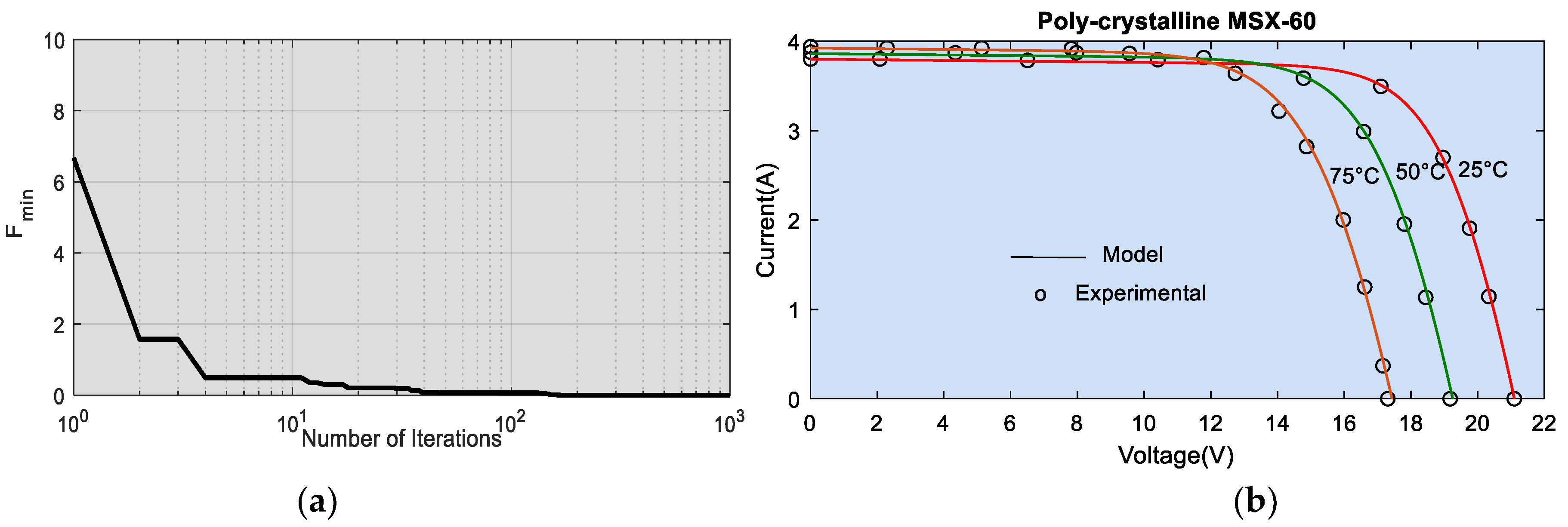

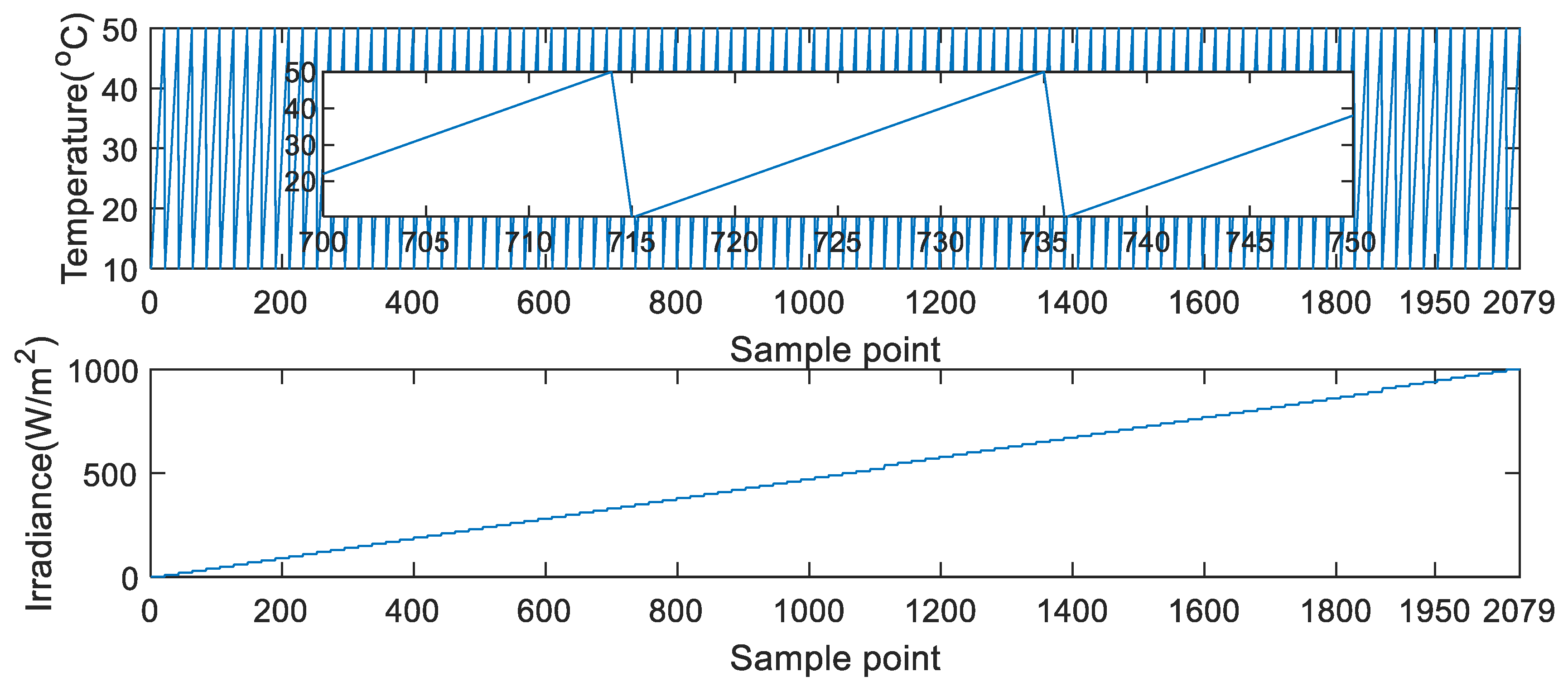
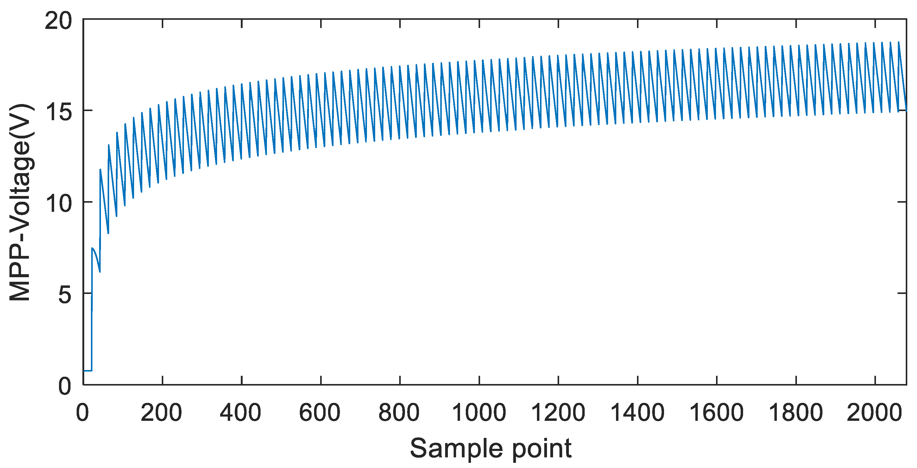
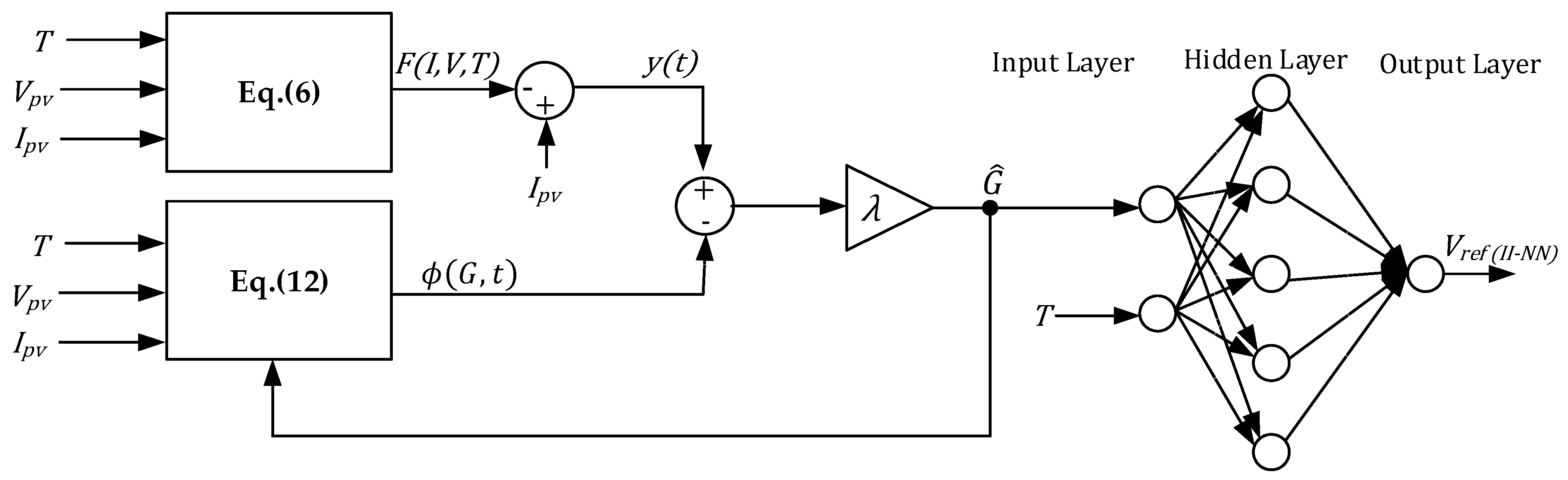
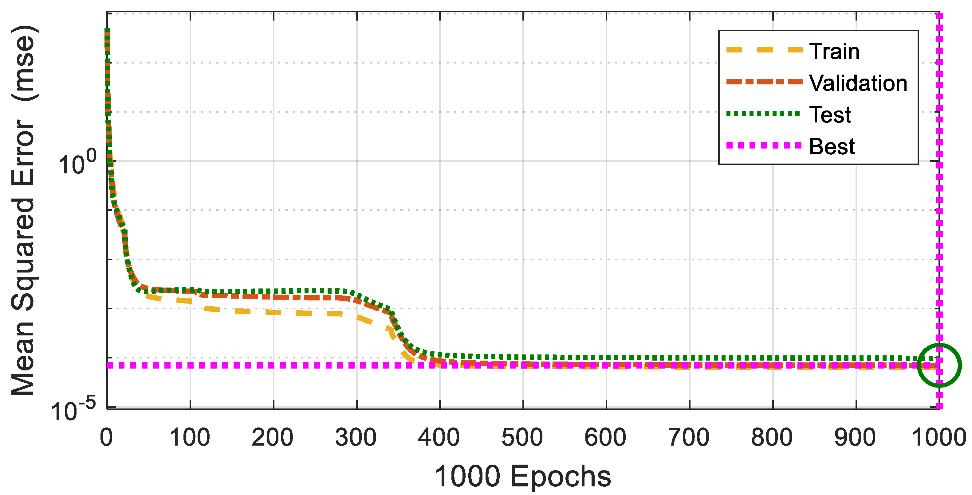
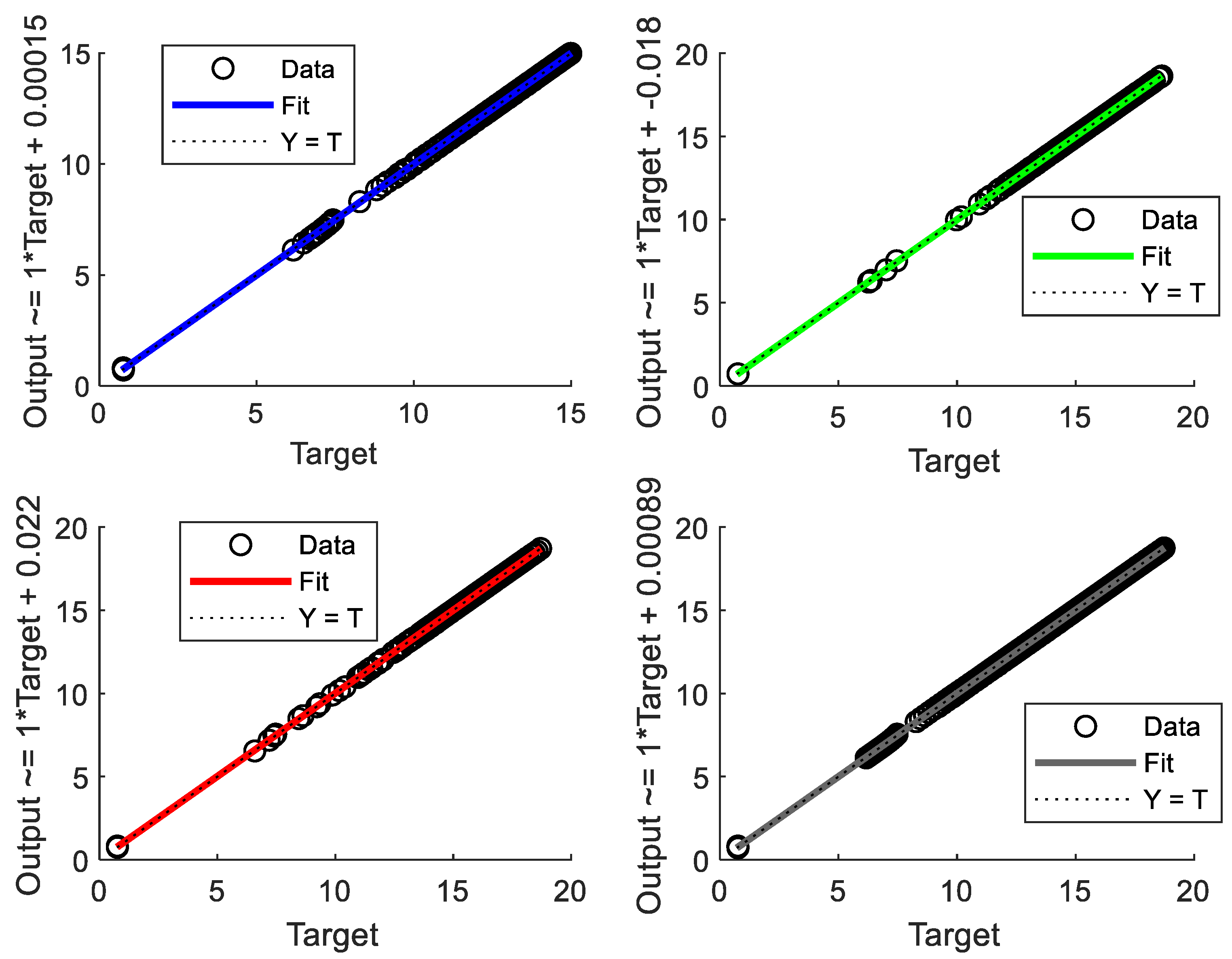
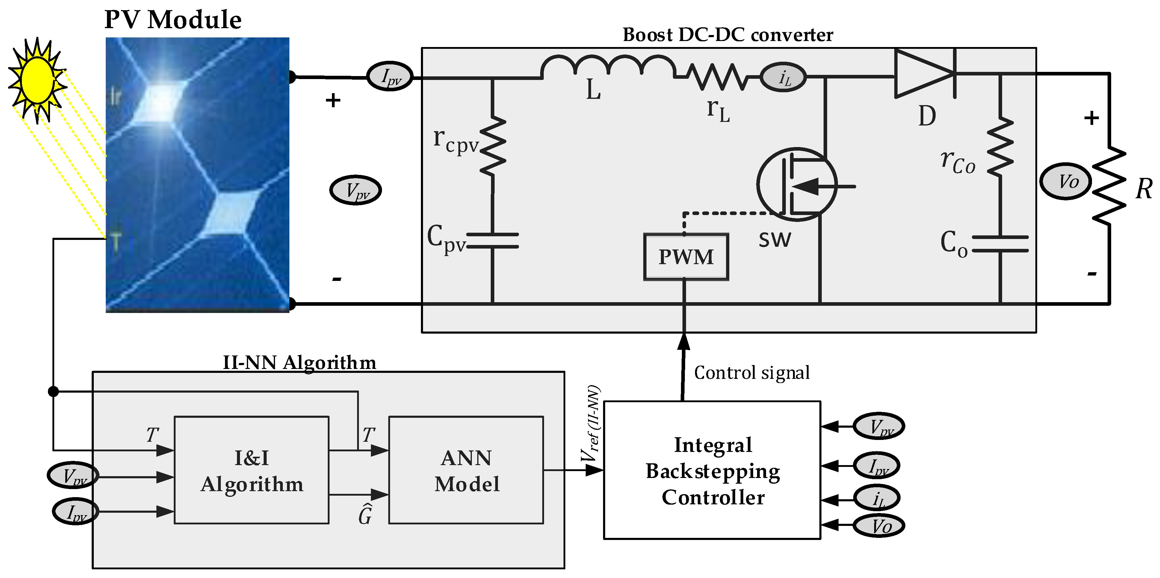
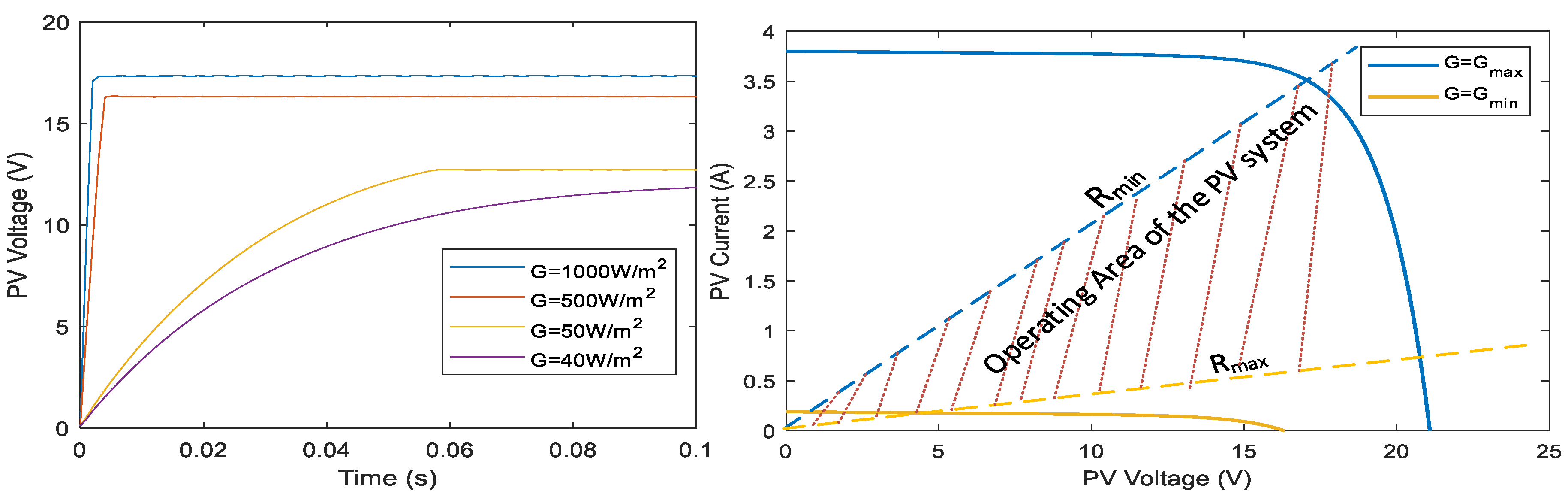
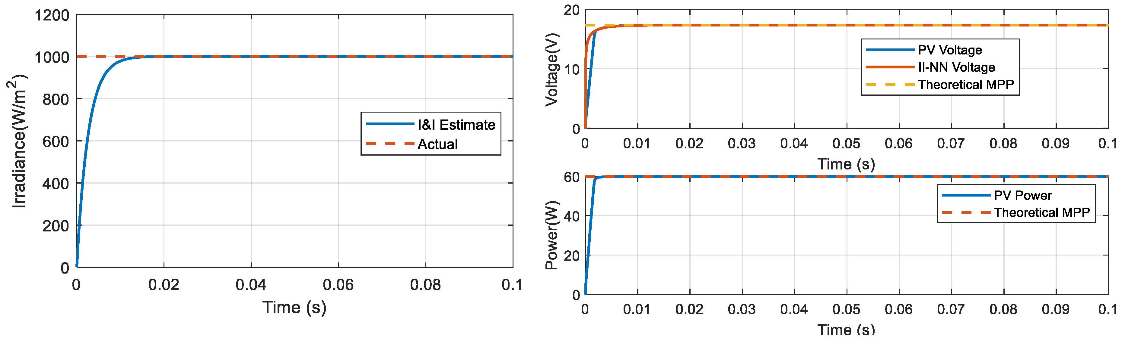
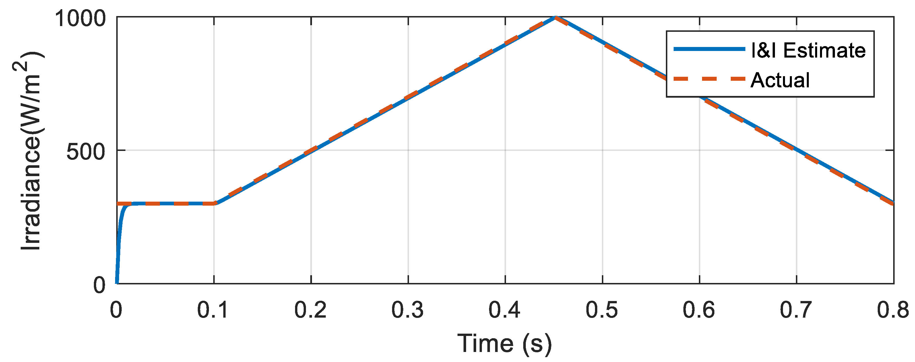
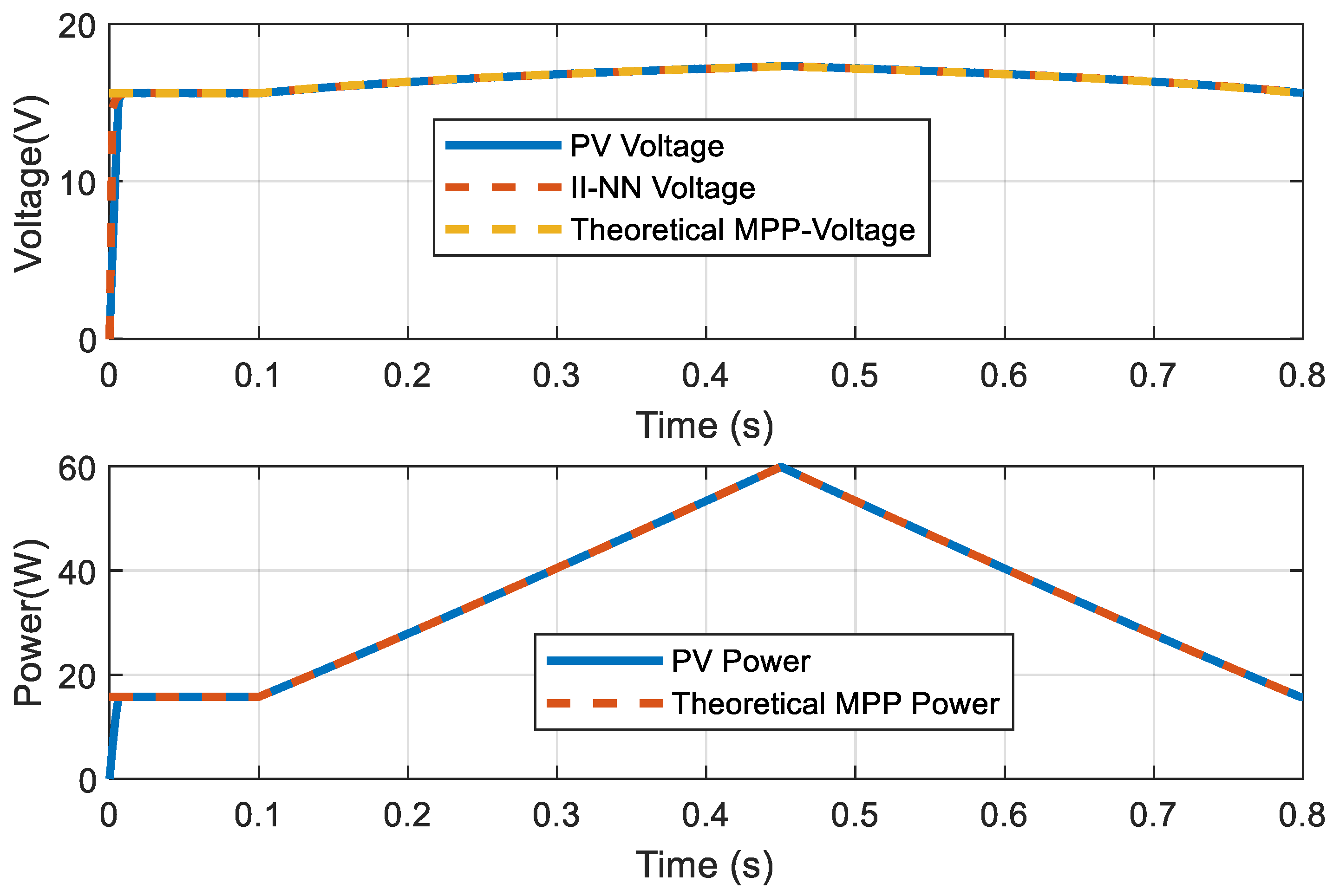
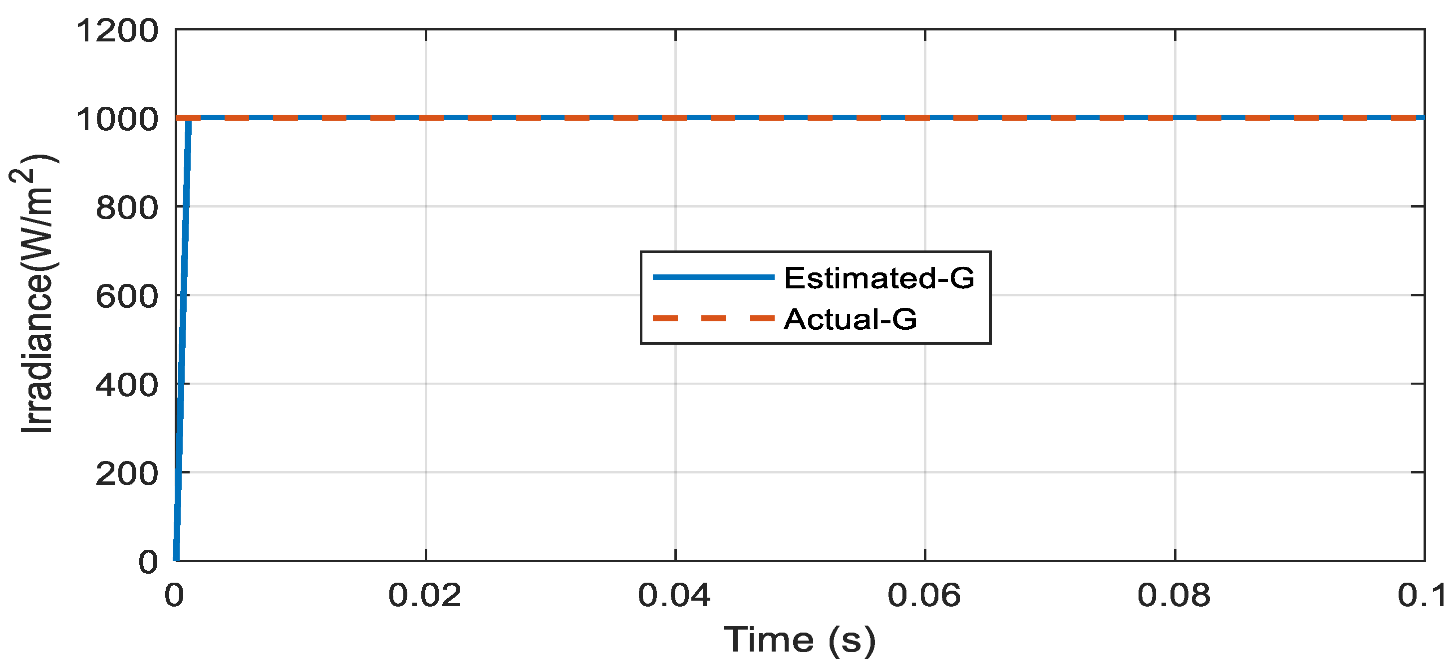
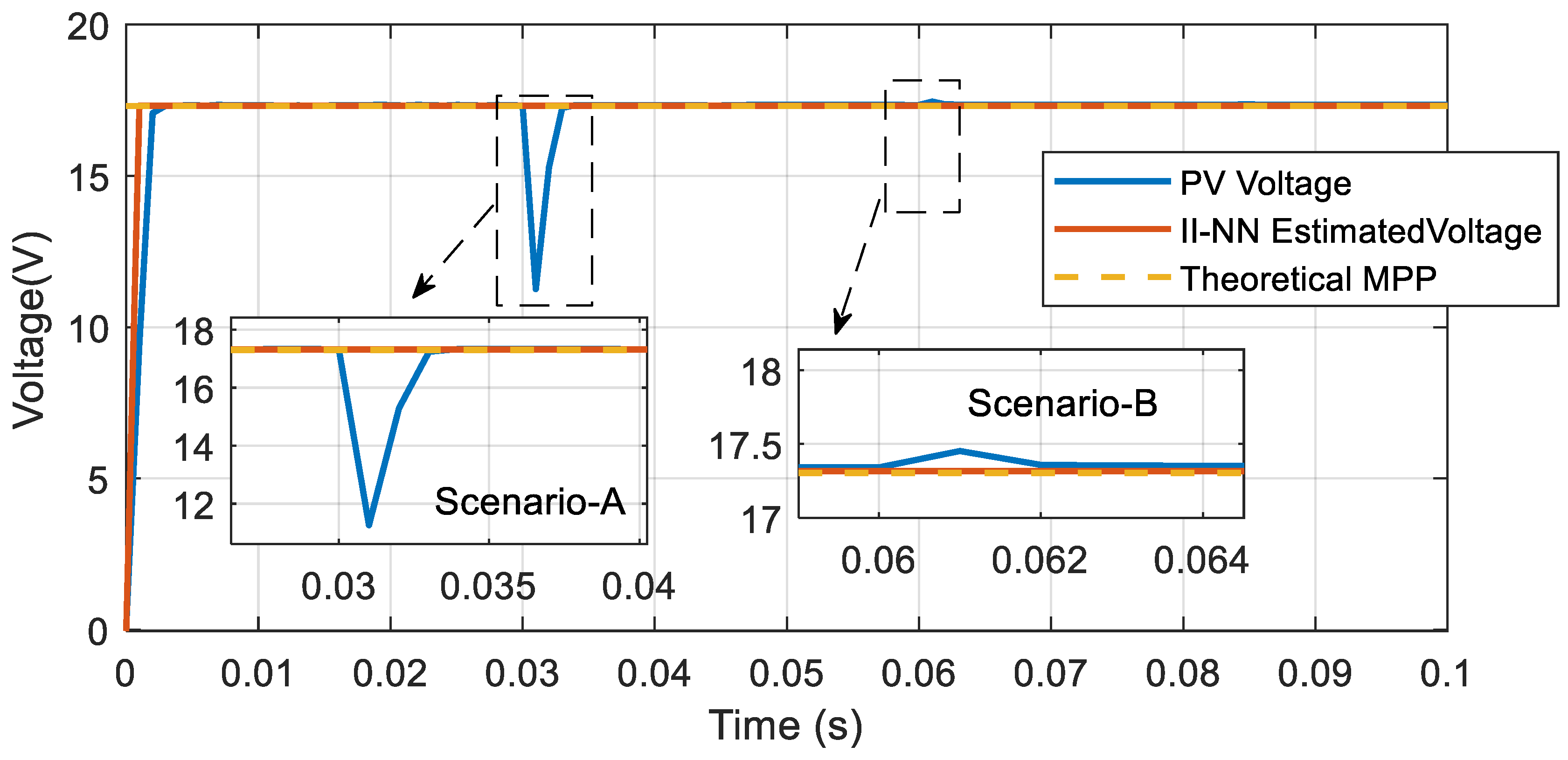
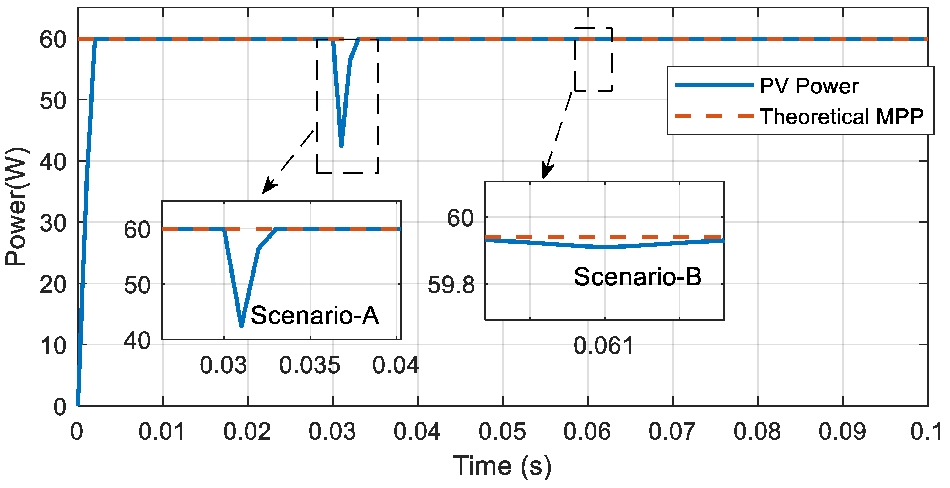

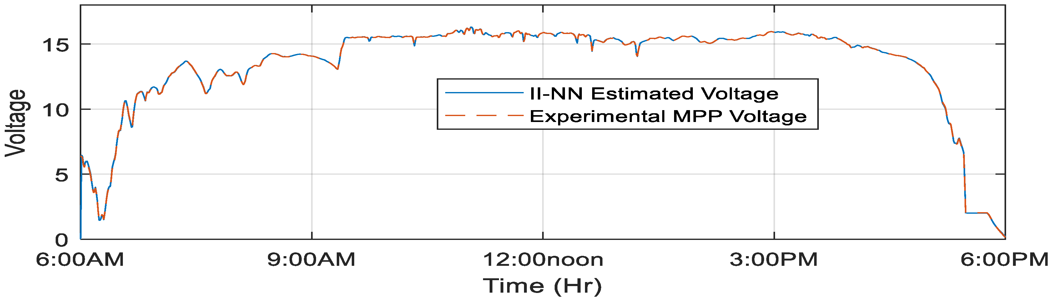
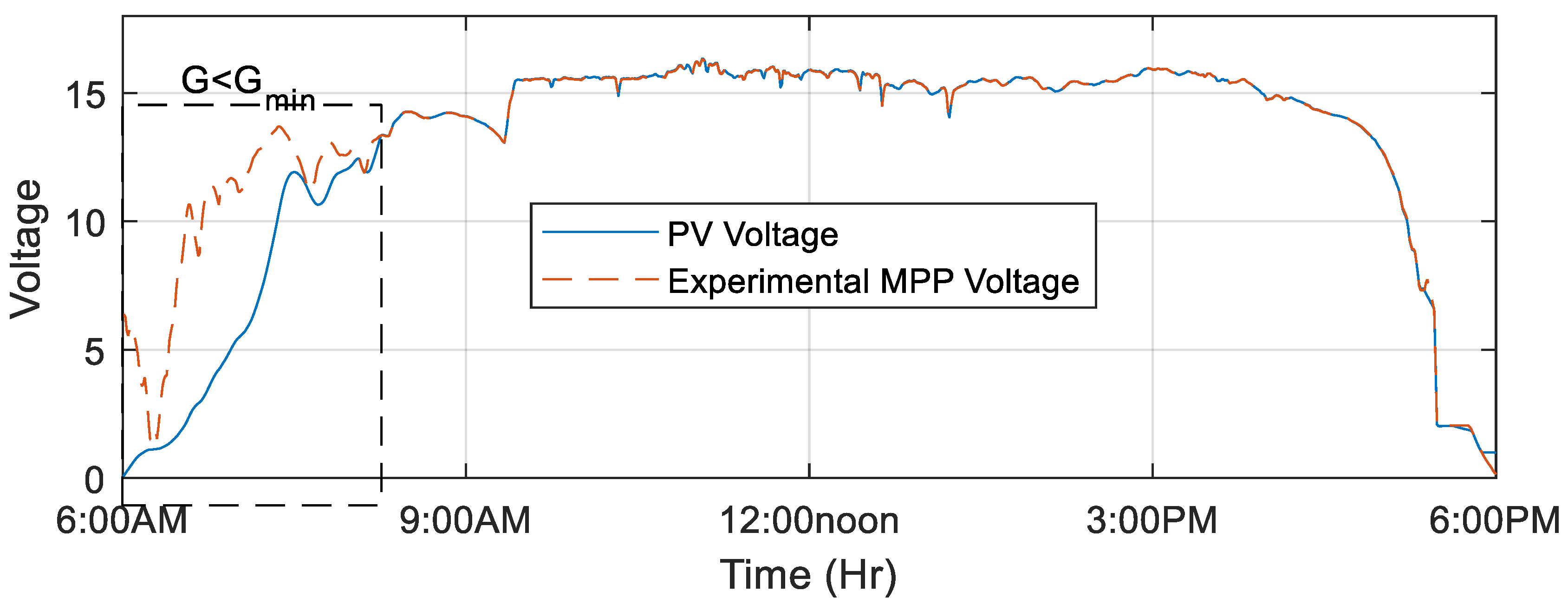
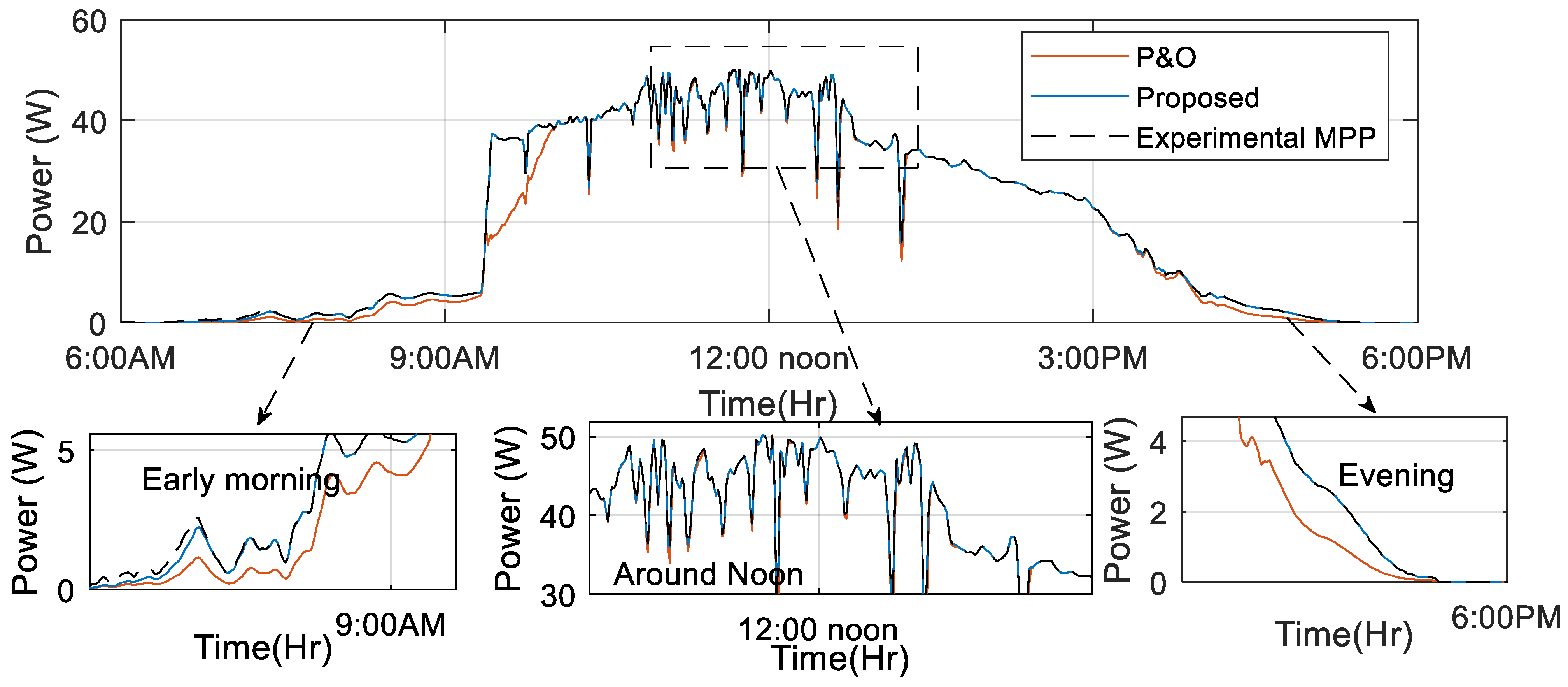
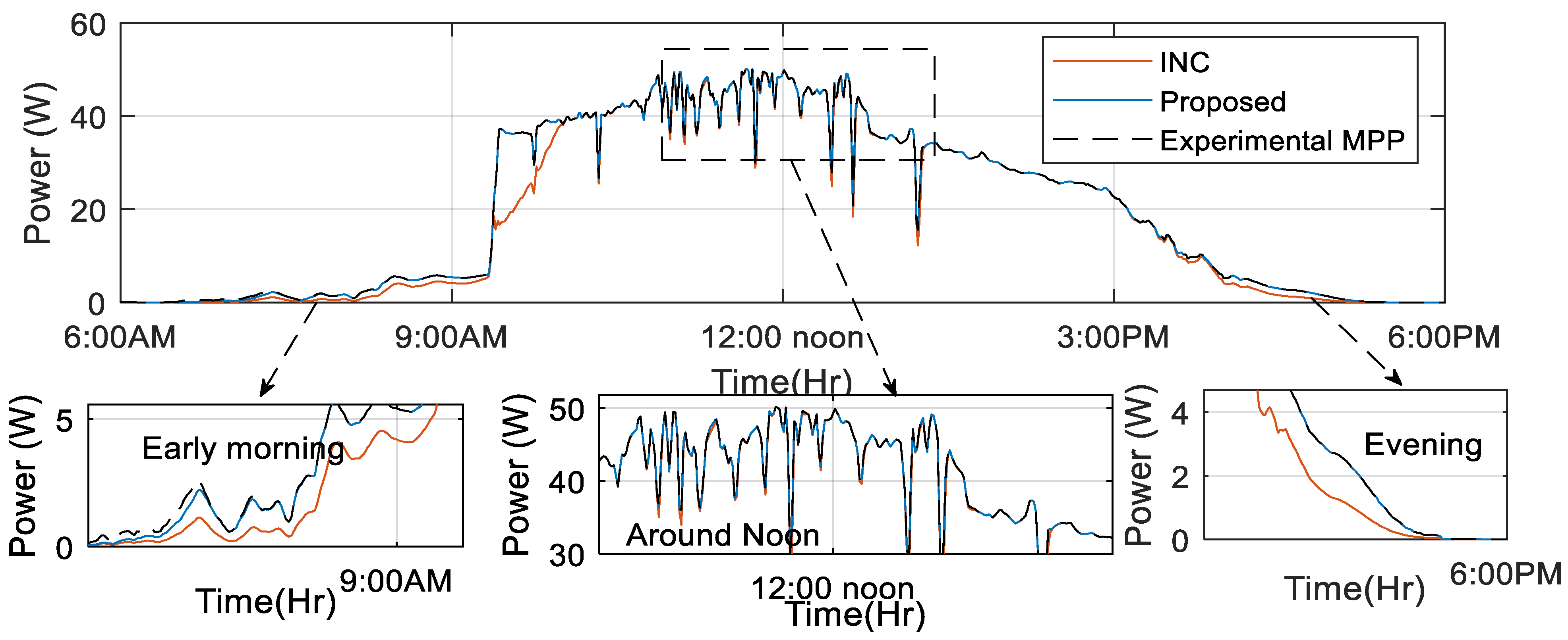
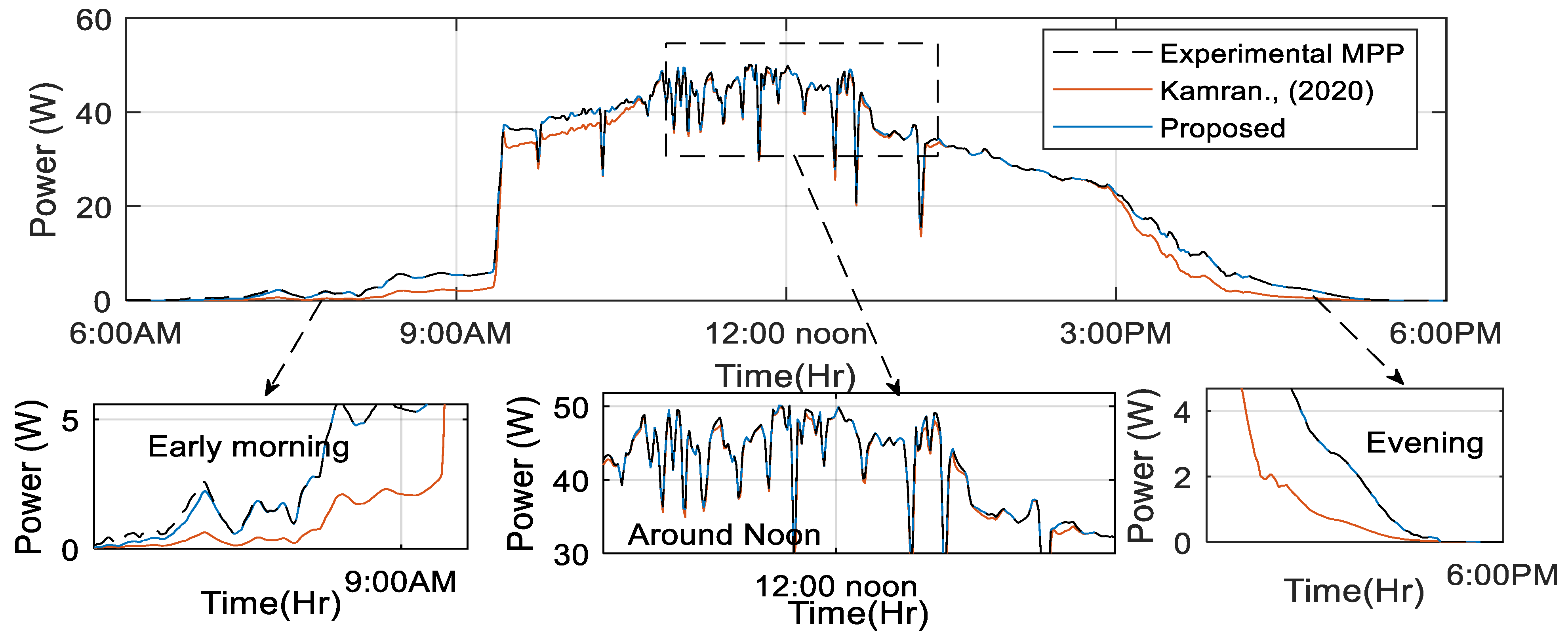
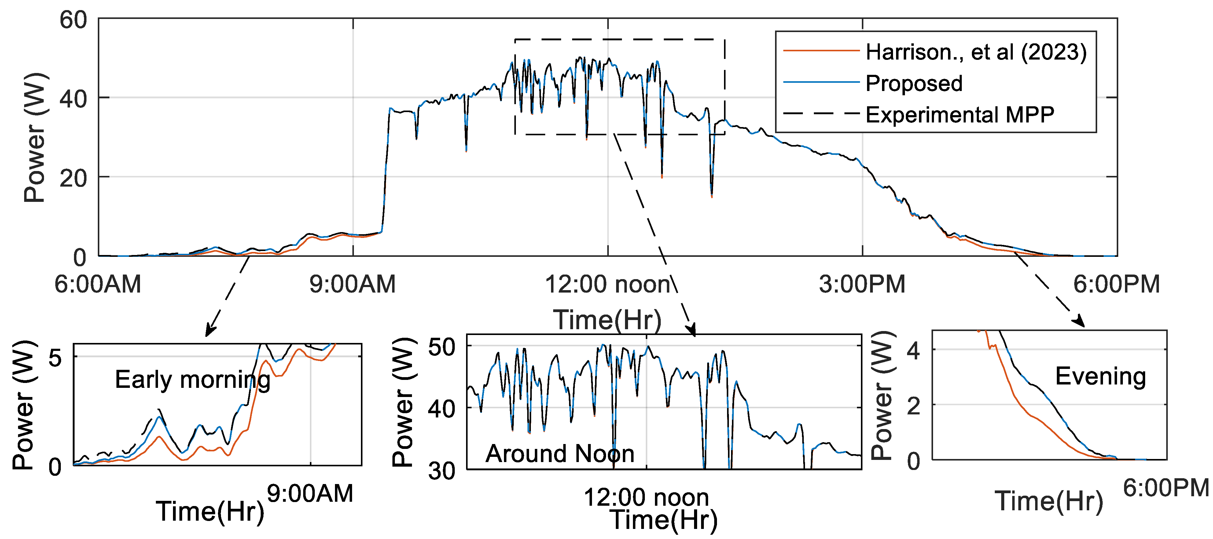
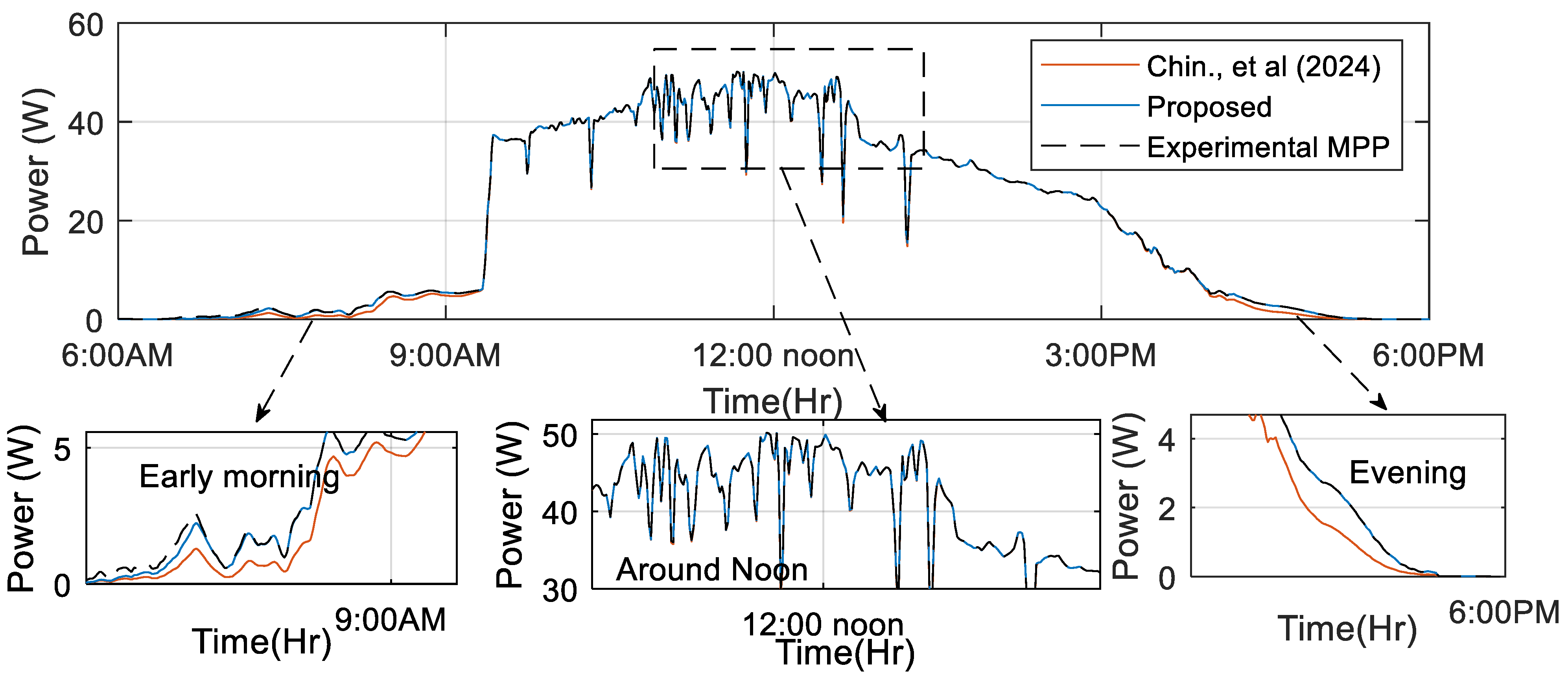
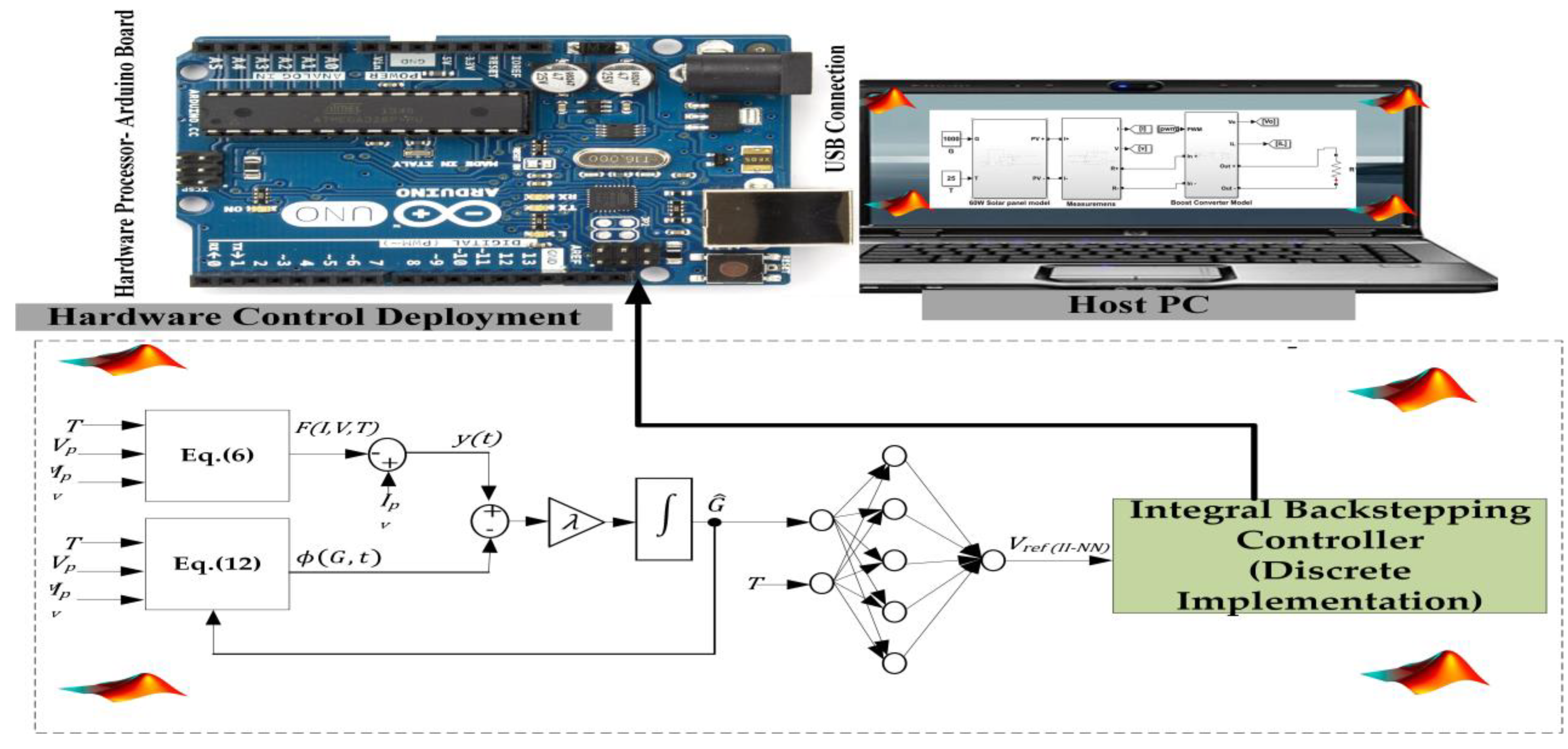
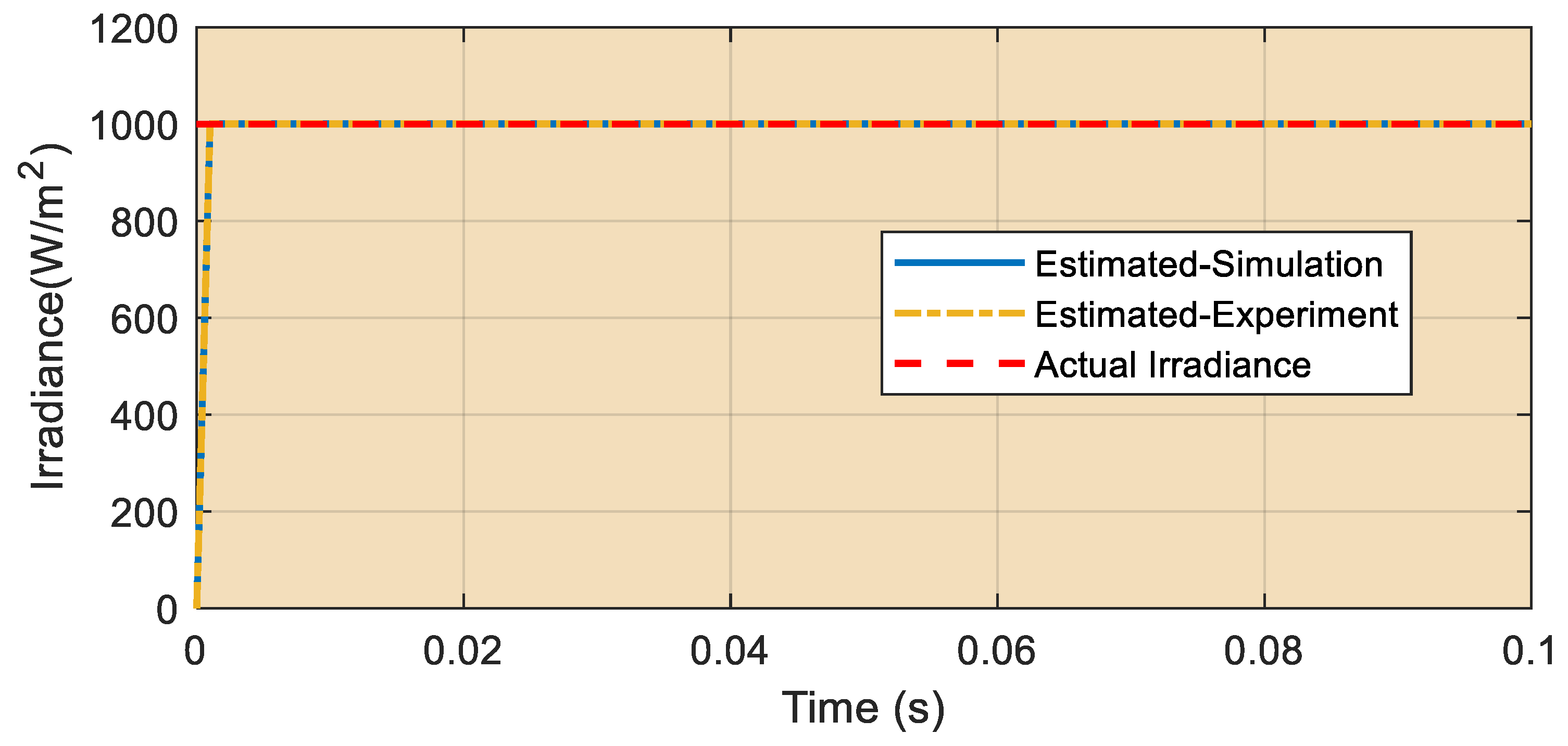
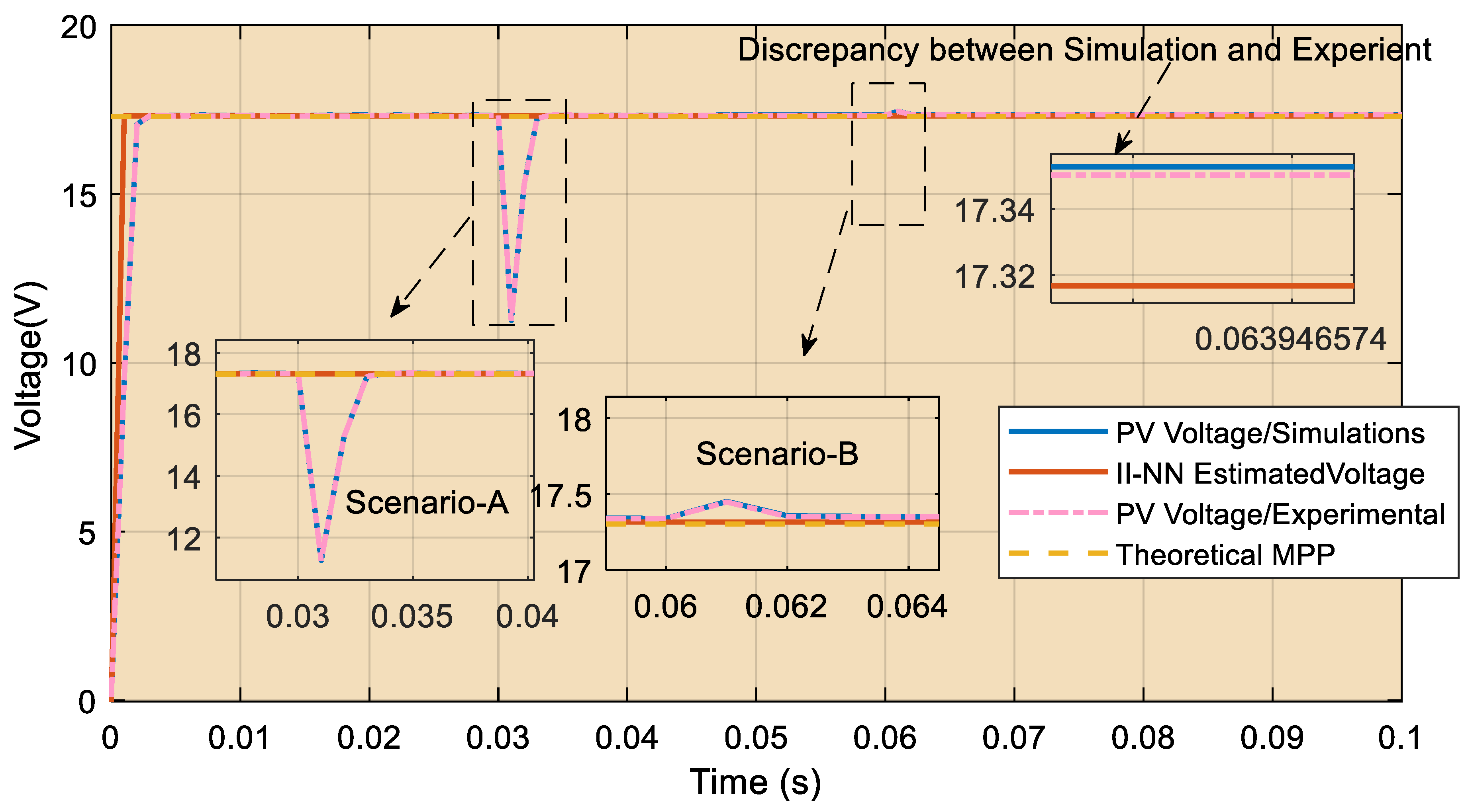
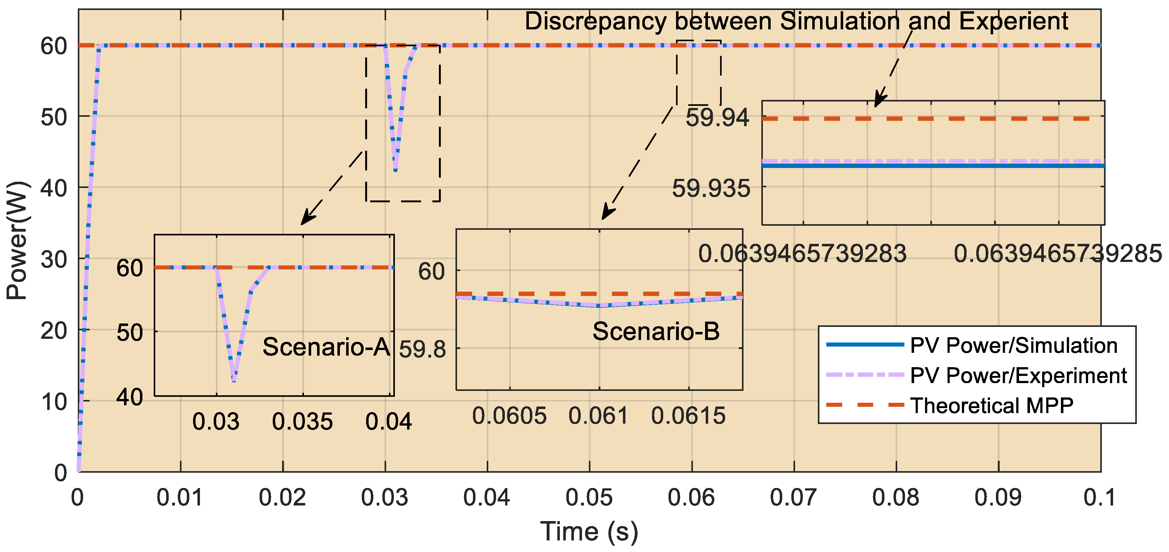
Disclaimer/Publisher’s Note: The statements, opinions and data contained in all publications are solely those of the individual author(s) and contributor(s) and not of MDPI and/or the editor(s). MDPI and/or the editor(s) disclaim responsibility for any injury to people or property resulting from any ideas, methods, instructions or products referred to in the content. |
© 2024 by the authors. Licensee MDPI, Basel, Switzerland. This article is an open access article distributed under the terms and conditions of the Creative Commons Attribution (CC BY) license (https://creativecommons.org/licenses/by/4.0/).