Article

Power Allocation Control Strategy of DC/DC Converters Based on Sliding Mode Control

1
College of Information and Electrical Engineering, Shenyang Agricultural University, Shenyang 110866, China
2
Electric Power Research Institute, State Grid Liaoning Electric Power Co., Ltd., Shenyang 110055, China
3
State Grid Liaoyang Power Supply Company, Liaoyang 111018, China
*
Author to whom correspondence should be addressed.
Energies 2024, 17(18), 4628; https://doi.org/10.3390/en17184628
Submission received: 2 August 2024 / Revised: 2 September 2024 / Accepted: 14 September 2024 / Published: 15 September 2024

Abstract

:
In the DC microgrid system, the bidirectional DC/DC converter is one of the most important components; thus, research on its control strategy has attracted widespread attention. Firstly, the single bidirectional DC/DC converter based on a sliding mode (variable structure) control (SMC) strategy exhibits an inherent contradiction between the reaching time and the chattering phenomenon. In order to address this problem, an SMC strategy based on the improved exponential reaching law was designed. This control strategy modifies the constant-speed reaching term and introduces the system state variable to indicate the chattering level, which not only improves the dynamic performance of the bidirectional DC/DC converter but also suppresses the chattering problem. Secondly, the bidirectional DC/DC converter group based on the traditional droop control strategy exhibits an inherent contradiction between load power allocation and bus voltage stabilization. In order to address this problem, an improved droop control strategy that takes the line impedance characteristics into account is proposed. This control strategy modifies the traditional droop control strategy by introducing virtual resistance and uses DC bus voltage information to replace the line impedance value. This ensures the accuracy of power allocation and stability of the DC bus voltage simultaneously. Finally, the stability of each designed strategy is verified individually. The combination of the two control strategies is applied to a group of bidirectional DC/DC converters group to conduct a semi-physical simulation experiment, and the results verify that the proposed control strategies are effective and feasible.

1. Introduction

In recent years, as issues related to energy and the environment have become increasingly serious, and in line with the “emission peak and carbon neutrality” target, renewable energy development has gained importance. A microgrid is a bridge between a renewable energy system and an energy storage system, and can be categorized as a DC microgrid or an AC microgrid. Microgrids integrate different types of renewable energy as well as reduce the control difficulties of distributed energy. Compared to AC microgrids, DC microgrids have higher efficiency because they do not need to consider AC/DC power conversion. DC microgrids are not affected by problems such as reactive power, skin effect, and power quality. Therefore, DC microgrids have received broader attention [1].
Research studies on DC microgrids mainly focus on planning, operation, and control strategies. The main research problems in DC microgrid system control strategies are poor dynamic performance and unreasonable power allocation of distributed generation. To improve the dynamic performance of the DC microgrid system, sliding mode control (SMC) is increasingly used in the control strategies of bidirectional DC/DC converters due to its fast response speed and good dynamic performance [2,3,4,5,6,7,8,9,10,11,12]. In reference [2], to simplify the design of the second-order sliding mode controller, the output voltage was set to be the only feedback quantity, which reduced the system’s anti-interference ability, and the robustness of the system was affected. Reference [3] designed a power switching scheme for a bidirectional DC/DC converter based on SMC, which effectively shortened the sliding mode arrival time and improved the dynamic performance of the controlled system, but there were still chattering problems. Reference [4] determined the sliding mode parameters using quantitative mathematical relationships to achieve system robustness, but it was difficult to select the circuit parameters due to limitations on the duty cycle. Focusing on the high-frequency chattering phenomenon, references [5,6,7,8] proposed SMC strategies based on a variable-parameter reaching law and a hybrid reaching law, which combined exponential and terminal techniques. Both failed to achieve complete suppression and increased the control complexity. References [9,10,11,12] further proposed a new sliding mode reaching law, an improvement to the power reaching law. Due to its discretization, the output voltage ripple increased, and the chattering problem persisted as before.
For reasonable power allocation in DC microgrid systems, the traditional droop control does not consider the impact of line impedance, which leads to unreasonable power allocation and common bus voltage deviation [13,14,15]. Reference [16] reduced the voltage deviation by introducing the voltage rate of change to improve the power allocation accuracy, but the results still had some errors. References [17,18] proposed a secondary control method supplemented with additional current and voltage measurements, due to which improved the power allocation accuracy. However, there were still common bus voltage deviations. But if the common bus voltage is collected directly, it will increase the transmission pressure [19]. References [20,21,22] adjusted the droop coefficients by considering load dynamic changing and virtual impedance, which can weaken the influence of line impedance on power allocation. However, the results showed that there were still errors.
Based on the above studies, the advantages and disadvantages of the methods proposed by other authors are summarized in Table 1. A sliding mode control strategy based on the improved exponential reaching law is provided in this paper. By revising the constant-speed reaching term and introducing system state variables to describe the chattering level, the proposed strategy can improve the dynamic performance of the bidirectional DC/DC converter and suppress the chattering problem. In addition, this paper proposes an improved droop control strategy, considering the line impedance characteristics; it solves the inherent contradiction between power allocation and voltage deviation caused by the line impedance characteristics. Finally, the stability of the two control strategies are verified individually and the combination of the two control strategies is used in a bidirectional DC/DC converter group. The experimental verification results indicate the effectiveness of the proposed control strategies.

2. DC Microgrid System Structure

The DC microgrid operation mode is categorized into grid-connected and islanded operations. The superiority of the control strategy is more obvious in the islanded DC microgrids than in the grid-connected DC microgrids. This paper’s research objective focuses on the islanded DC microgrid. Renewable energy, specifically photovoltaic, is applied to provide energy for the DC microgrid. The maximum power point tracking control strategy is adopted and the reference voltage of the DC bus is 750 V. The hybrid energy storage system, including the battery and hydrogen storage, maintains the balance of the energy flow on the bus. In particular, the hydrogen energy storage system facilitates the charging process by completing the hydrogen production from water electrolysis through an electrolytic cell, and the discharging process through a hydrogen fuel cell. Both components exhibit slow dynamic response characteristics, but the whole process can be pollution-free.
Each link is connected to the common bus through the power electronic converter. The bidirectional DC/DC converter not only completes the voltage conversion but also stabilizes the DC bus voltage. The functional diagram and the equivalent DC microgrid structure are shown in Figure 1 and Figure 2. In Figure 2, the blue part represents a hybrid energy storage system consisting of battery and hydrogen storage, the yellow part represents a photovoltaic power generation system, and the green part represents a DC load.
A DC/DC converter is an important part of the DC microgrid; it can be classified into isolated and non-isolated types, which are categorized according to whether there is electrical isolation between the converter’s input and output. Non-isolated DC/DC converters can be categorized into single-tube, double-tube, and four-tube converters, among which, there are six types of single-tube DC converters—the buck converter, boost converter, buck–boost converter, spic converter, Ćuk converter, and Zeta converter. Isolated DC/DC converters can be categorized into forward and flyback; the two-tube category has a two-tube forward, two-tube flyback, push-pull, and half-bridge, and the four-tube category encompasses the full-bridge type. Although non-isolated converters are not as safe as isolated converters, their simple structure, low cost, high efficiency, compact size, and ease of integration make them widely used in portable electronics, electric vehicles, and distributed power systems. In this paper, the control strategy of non-isolated converters is investigated.

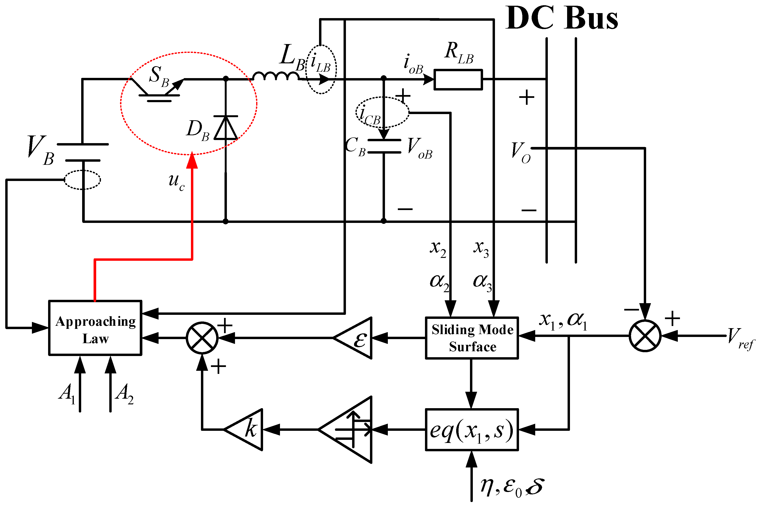
3. SMC of a Single Bidirectional DC/DC Converter

3.1. Sliding Mode Controller Design

The most important step in the SMC determining the sliding mode surface. The output signal of the sliding mode controller is used to control the switching action of the bidirectional DC/DC converter and force the system to follow a predetermined path in the state space, which is called the sliding mode surface or sliding surface. According to the sliding mode surface function s ( ) = 0 , the inductor current state variable x 3 is added to the design in this section, as follows:
s ( x ) = α 1 x 1 + α 2 x 2 + α 3 x 3 = J T x
x 1 = U r e f u 0 x 2 = C 1 i C x 3 = i L = L 1 ( u s u i u 0 ) d t
where α 1 ,   α 2 ,   α 3 are the sliding coefficients; L ,   C are the line inductance and capacitor, respectively, serving as energy storage inductors, L B ,   L H , and filter capacitors, C B ,   C H , for battery storage systems and hydrogen storage systems, respectively; u i ,   u 0 are the input and output voltage steady-state values, and they represent V B ,   V H and V o B ,   V o H for battery storage systems and hydrogen storage systems, respectively; U r e f is the reference voltage. Thus, we have the following:
x ˙ 1 x ˙ 2 x ˙ 3 = 0 1 0 ( L C ) 1 ( R L C ) 1 0 0 0 0 x 1 x 2 x 3 + 0 ( L C ) 1 u i L 1 u i u s + 0 ( L C ) 1 U r e f L 1 u 0
u s = 1 , S > 0 0 , S < 0
In order to guarantee the sliding mode state, it is necessary to satisfy the local reachability condition, i.e., lim s 0 s s ˙ < 0 .
Whether s 0 + ,   u s = 1 or s 0 ,   u s = 0 , they all fulfill the local accessibility conditions,
lim s 0 s s ˙ = lim s 0 s [ α 1 α 2 ( R C ) 1 ] C 1 i C ( α 2 C 1 α 3 ) L 1 ( u i u 0 ) < 0
lim s 0 s s ˙ = lim s 0 s [ α 1 α 2 ( R C ) 1 ] C 1 i C + ( α 2 C 1 α 3 ) L 1 u 0 < 0
The sliding coefficients α 1 ,   α 2 ,   α 3 need to satisfy Equations (5) and (6) in order to ensure that the bidirectional DC/DC converter satisfies the operating conditions; that is, the existence of SMC is guaranteed.
The design of the reaching law in SMC is also an important implementation step. The sliding mode reaching law ensures the dynamic performance quality of the system during the approaching process, starting from any point of the DC microgrid system to the end of the sliding mode surface. Therefore, whether the design of the reaching law is reasonable or not can directly affect whether the microgrid system reaches the sliding mode surface with the expected route. In order to ensure the reaching speed of the sliding mode controller, the exponential reaching law is generally used, and its expression is as follows:
s ˙ = k sgn ( s ) ε s
where k > 0 , ε > 0 .
Then, we have the following:
d s d t = a d x 1 d t + d x 2 d t = ( a 1 R L C ) x 2 + c b u s = k sgn ( s ) ε s
The output voltage of the sliding mode controller and the time reaching the sliding mode surface can be obtained, as shown in Equations (9) and (10), as follows:
u s = 1 b [ ( a 1 R L C ) x 2 + c + k sgn ( s ) + ε s ]
t 1 = k + k 2 + 2 ε s ( 0 ) ε
In the above equation, 1 b k sgn ( s ) is a discontinuous term, which is the most fundamental reason for the chattering phenomenon of SMC, and the speed of reaching the sliding mode surface depends on the value of the parameter ε , so the reaching time of the SMC and the chattering phenomenon are contradictory. Therefore, in this section, an improved exponential reaching law is proposed to revise the constant-speed reaching term, so that it is closely related to the current state of the system. The state variable x 1 is introduced to describe the chattering level; that is, the constant-speed reaching term decreases with the decrease of x 1 , effectively suppressing the chattering problem, as shown in Equations (11) and (12):
u s = 1 b [ ( a 1 R L C ) x 2 + c + k sgn ( s ) + ε s ]
t 1 = k + k 2 + 2 ε s ( 0 ) ε
where lim t x 1 = 0 , 0 < ε 0 < 1 , η > 1 , δ > 0 .
s ˙ ( x ) = α 1 x ˙ 1 + α 2 x ˙ 2 + α 3 x ˙ 3
By combining Equation (13) with Equation (3), we obtain the following:
u e q = u s = 1 u i A 1 k e q ( x 1 , s ) sgn ( s ) + ε s + A 2 ( α 2 R C 2 α 1 C ) i C + u 0
where
A 1 = L C α 2 α 3 C A 2 = L R C α 2 α 1 R C α 2 α 3 C
Then, we have the following:
u c = u e q * = β u i u e q = β A 1 k e q ( x 1 , s ) sgn ( s ) + ε s + A 2 ( α 2 R C 2 α 1 C ) i C + u 0
u r a m p = β u i
where the duty cycle d meets 0 < d < u c u r a m p < 1 .
Based on the above analysis, the SMC structure based on the improved exponential reaching law proposed in this section is shown in Figure 3.

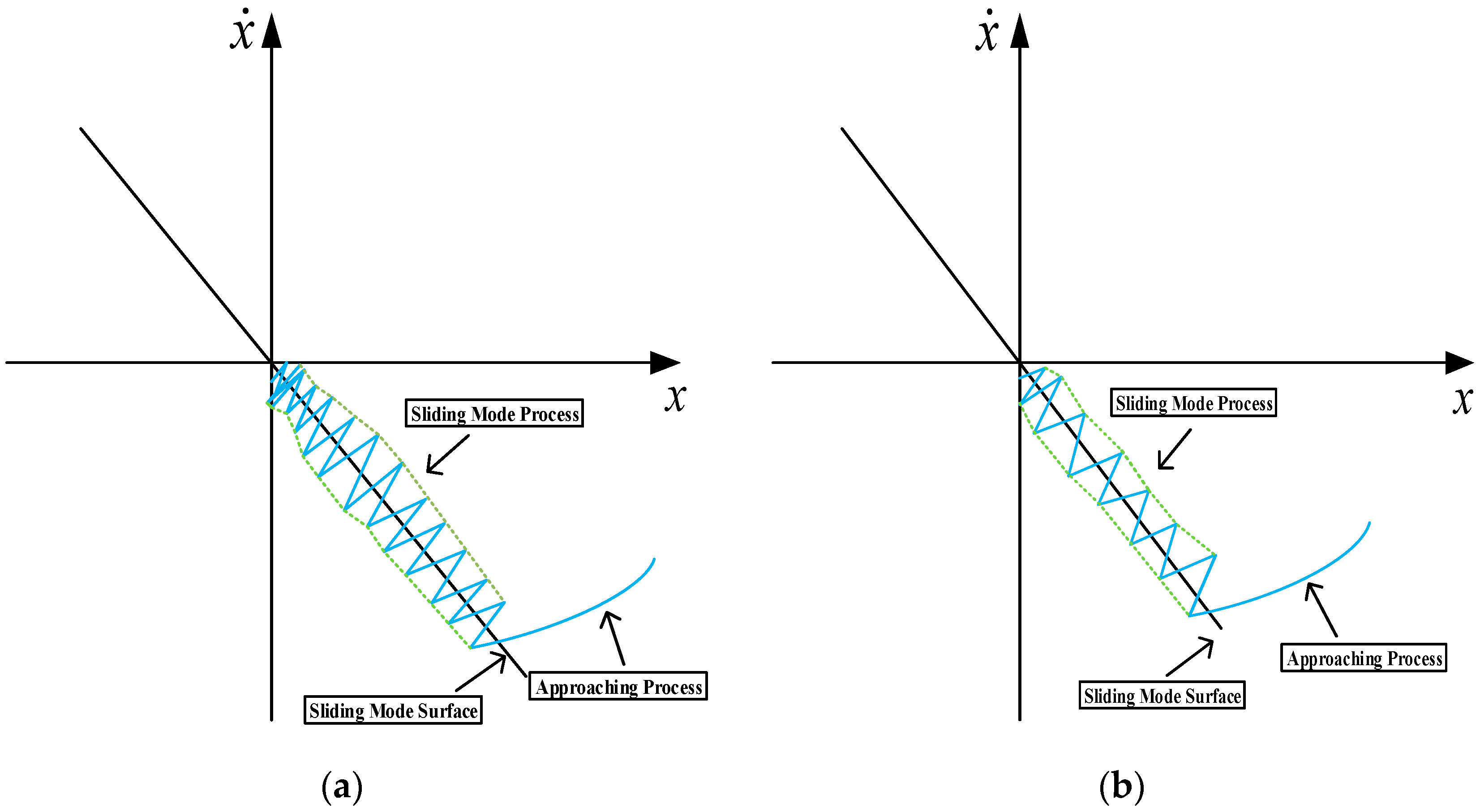
3.2. Stability Verification of the Improved Sliding Mode Reaching Law

The stability theory of Lyapunov function V = 1 2 s 2 is used to verify the stability of the improved exponential reaching law proposed in this section. When the condition shown in Equation (18) is satisfied, it indicates that the sliding mode reaching law is stable.
V ˙ = s s ˙ 0
s s ˙ = k e q ( x 1 , s ) sgn ( s ) ε s s = k e q ( x 1 , s ) s ε s 2
In Equation (19), since k > 0 , ε > 0 , e q ( x 1 , s ) > 0 , then s s ˙ 0 . Therefore, it can be concluded that the improved exponential reaching law proposed in this paper can control the sliding mode motion of the system in a finite time and the stability and reachability conditions are satisfied.
When approaching the sliding mode surface, the reaching speed is determined by the variable-speed reaching term; at this time, the speed of the exponential reaching term is 0. Meanwhile, the introduction of the state variable x 1 to revise the coefficient of the variable-speed reaching term allows x 1 to approach the sliding mode surface under the action of the sliding mode reaching law; that is, the motion process of the state variable x 1 reaches the origin motion, which reaches 0. Thus, the coefficient of the variable-speed reaching term reaches 0, and the objective of suppressing chattering is achieved.
For the analysis of the SMC structure based on the improved exponential reaching law shown in Figure 4, when the motion direction of the moving point of the system is away from the sliding mode surface, s , the coefficient of the variable-speed reaching term is k ε 0 , and k ε 0 > k . Therefore, the speed of the variable-speed reaching term increases, and when added to the exponential reaching term, the reaching speed is faster. When the motion direction of the moving point of the system is close to the sliding mode surface, at this time s 0 , the coefficient of the variable-speed reaching term is k η x 1 1 ; that is, s ˙ = k x 1 η sgn ( s ) ε s . The sliding mode motion comparison under two exponential reaching laws is shown as follows:

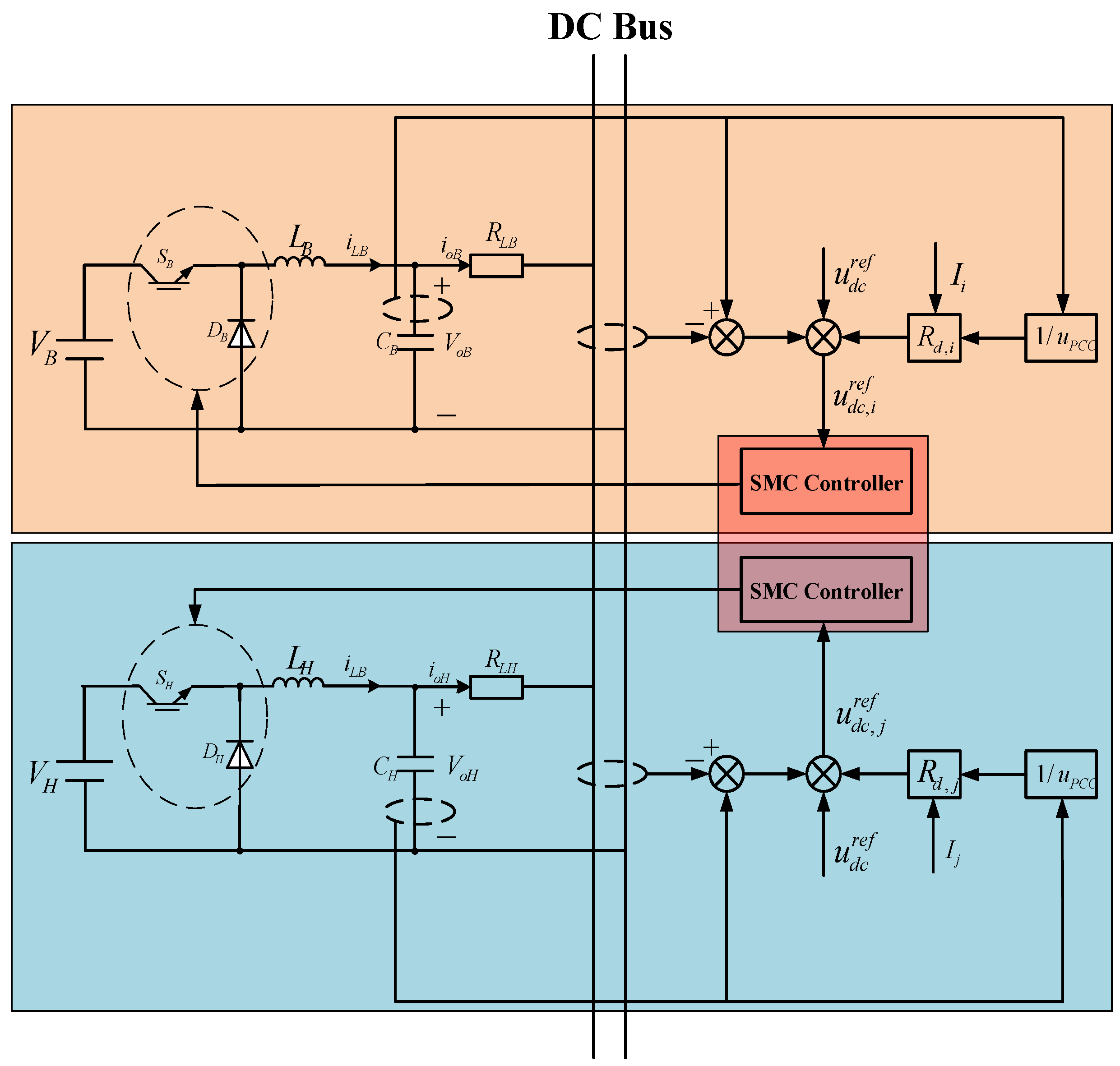
4. Power Allocation Control of Parallel Bidirectional DC/DC Converters

4.1. Improved Droop Controller Design

In the DC microgrid system, droop control is utilized to ensure the reasonable allocation of distributed generation, but the traditional droop control frequently ignores the influence of line impedance. Therefore, in order to address this problem, this section proposes improved measures based on the analysis of the traditional droop control, which not only ensures the allocation accuracy of distributed generation in the DC microgrid system but also maintains the DC bus voltage at the rated value.
In Figure 5, u d c r e f is the given initial voltage value of the converter; u d c is the converter terminal voltage; u P C C is the voltage at the DC bus; I is the output current of the converter; I l o a d is the load current; R l i n e is the line impedance from the converter to the DC bus; R l o a d is the load impedance; R d is the droop coefficient.
It can be seen in Figure 6 that when a smaller droop coefficient is selected, although the voltage deviation is reduced, the current allocation accuracy is reduced, which in turn leads to unreasonable power allocation. When a larger droop coefficient is selected, the current allocation accuracy is effectively improved, but at the same time, it also leads to an increase in the voltage deviation. Therefore, there is an inherent contradiction between higher current allocation accuracy and smaller voltage deviation under the traditional droop control. Only when the value of the following equation is 0 does the power satisfy reasonable allocation.
R l i n e , j R l i n e , i = ( u d c , j 1 ) R d , j ( u d c , i 1 ) R d , i
The traditional droop control strategy is improved as shown in Equation (21), with m i , m j denoting the virtual resistors for adaptive power allocation:
u d c , i = u d c r e f R d , i I i m i I i u d c , j = u d c r e f R d , j I j m j I j
Δ P i j = u d c , i ( R d , j + R l i n e , j + m j ) u d c , j ( R d , i + R l i n e , i + m i ) R d , j R d , i
We define the following: α i = u d c , i u P C C , α j = u d c , j u P C C ,
Δ P i j = α i ( R d , j + R l i n e , j + m j ) α j ( R d , i + R l i n e , i + m i ) R d , j R d , i = α i R d , i ( R d , j + R l i n e , j + m j ) α j R d , j ( R d , i + R l i n e , i + m i ) α j R d , i ( R d , i + R l i n e , i + m i )
α i R d , i ( R d , j + R l i n e , j + m j ) α j R d , j ( R d , i + R l i n e , i + m i ) = 0
Then, we have the following:
m i = ( α i 1 ) R d , i R l i n e , i m j = ( α j 1 ) R d , j R l i n e , j
Since the line impedance value cannot be accurately obtained in the actual system, the voltage information at the common point of the DC bus is introduced in the improved droop control.
m i = ( α i 1 ) R d , i ( u d c , i u P C C ) / I i m j = ( α j 1 ) R d , j ( u d c , j u P C C ) / I j
Substituting into Equation (21) gives the following:
u d c , i = u d c r e f u d c , i u P C C R d , i I i + u d c , i u P C C u d c , j = u d c r e f u d c , j u P C C R d , j I j + u d c , j u P C C
In summary, optimizing the traditional droop control into the improved droop control, as shown in Equation (27), can improve the power allocation accuracy of the DC microgrid system. Meanwhile, the improved droop control proposed in this section only needs to share the DC bus voltage information in the system, which can reduce the requirements on the communication system, ensure the plug-and-play function of the distributed generation, and ensure the stability of the DC bus voltage. The schematic diagram is shown in Figure 7.

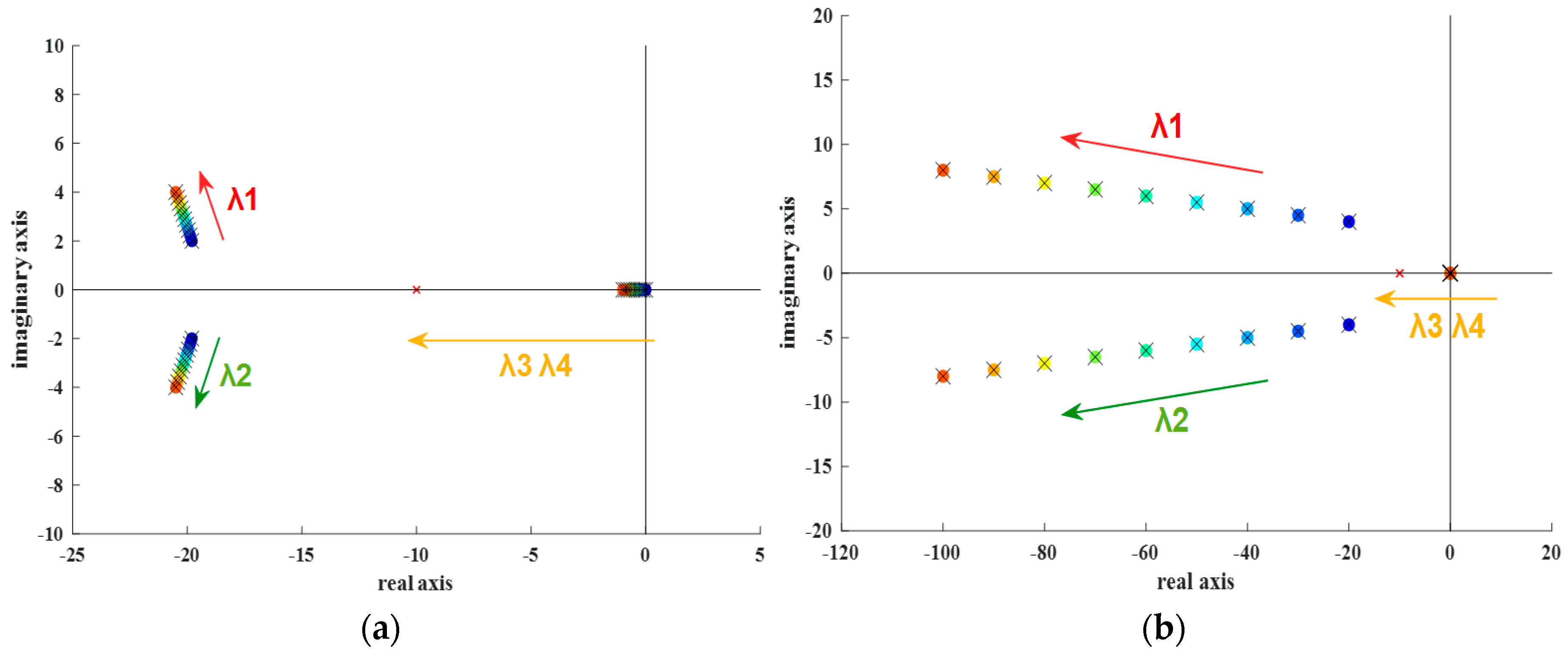
4.2. Stability Verification of the Improved Droop Control

The stability analysis is carried out by taking two equal-capacity parallel generation units as examples. The simplified diagram of the control structure of the two DG units is shown in Figure 8, in which the DC voltage closed-loop transfer function ≈ 1. The design of the correction link of the droop control is equivalent to an inertial link [23] and is the cut-off frequency of the low-pass filter.
u d c , i = R l i n e , i I i + R l o a d ( I i + I j ) u d c , j = R l i n e , j I j + R l o a d ( I i + I j )
I i = β i u d c , i λ u d c , j I j = β j u d c , j λ u d c , i
where
β i = R l i n e , j + R l o a d R l i n e , i R l o a d + R l i n e , j R l o a d + R l i n e , i R l i n e , j β j = R l i n e , i + R l o a d R l i n e , i R l o a d + R l i n e , j R l o a d + R l i n e , i R l i n e , j λ = R l o a d R l i n e , i R l o a d + R l i n e , j R l o a d + R l i n e , i R l i n e , j
From Figure 8, we have the following:
u d c , i = u d c r e f ω c ( s + 1 ) ( s + ω c ) R d , i ( β i u d c , i λ u d c , j ) u d c , j = u d c r e f ω c ( s + 1 ) ( s + ω c ) R d , j ( β j u d c , j λ u d c , i )
The characteristic equation is as follows:
s 4 + A s 3 + B s 2 + C s + D = 0
where
A = 2 ω c + 2 B = ω c 2 + ω c [ ( R d , i β i + R d , j β j ) + 4 ] + 1 C = 2 ω c 2 + ω c [ ( ω c + 1 ) ( R d , i β i + R d , j β j ) + 2 ] D = ω c 2 [ ( R d , i β i + R d , j β j ) + R d , i R d , j ( β i β j λ 2 ) + 1 ]
The root locus diagram of the above characteristic equation is plotted in Figure 9, where the parameter values are shown in Table 2. It can be seen that the dominant poles, λ 3 , λ 4 , are guaranteed to be stable, and the conjugate poles, λ 1 , λ 2 , tend to be far from the imaginary axis, whether the droop coefficient is kept constant and the cutoff frequency increases or the cutoff frequency is kept constant and the droop coefficient increases. Therefore, the system under the improved droop control proposed in this section is guaranteed to be stable.

5. Experimental Verification

In order to verify the feasibility and effectiveness of the proposed control strategies, the StarSim hardware-in-the-loop experimental platform was utilized to carry out the experimental verification [24]. The experimental environment is shown in Figure 10. The semi-physical experimental platform consisted of the host computer, an oscilloscope, a real-time simulation system, and a control board. Based on the DC microgrid equivalent structure shown in Figure 1 and the experimental parameters shown in Table 3, the experimental waveforms generated in the oscilloscope under different working conditions were exported first and then uniformly outputted after the same coordinate system.

5.1. DC Bus Voltage Comparison When the Load Power Changes

To ensure that the control parameters remain unchanged, three control strategies are compared and analyzed (namely PI, SMC based on the exponential reaching law, and SMC based on the improved exponential reaching law) in the following three stages:
Stage 1: The load power increases from 2 kW to 4 kW in 0.7 s; as the load power is larger than the PV output power in this stage, the DC bus voltage falls, and the hybrid energy storage system makes up the difference to maintain the stability of the DC bus voltage.
Stage 2: The load power reduces from 4 kW to 2 kW in 0.9 s; as the PV output power is larger than the load power in this stage, the DC bus voltage rises, and the hybrid energy storage system absorbs the excess power to maintain the stability of the DC bus voltage.
Stage 3: The load power increases from 2 kW to 3 kW in 1.1 s; the DC bus voltage fluctuations occur after a short period of time and then remain stable in this stage.
Comparisons of the initial waveforms of the DC bus voltage under the three control strategies (when the load power is disturbed) are shown in Figure 11.
From the experimental results shown in Figure 11, it can be seen that the voltage peaks of PI, SMC based on the exponential reaching law, and SMC based on the improved exponential reaching law are 1195 V, 997 V, and 757 V, respectively; the corresponding overshoots are 445 V, 247 V, and 7 V, respectively; and the voltage recovery times are 0.88 s, 0.72 s, and 0.1 s, respectively. It can be seen that the SMC based on the improved exponential reaching law proposed in this paper has the smallest overshoot and the shortest voltage recovery time when the load power is disturbed, and the dynamic response performance is improved.
When the load power is disturbed, the comparison of DC bus voltage waveforms under the three control strategies is shown in Figure 11.
Using the first stage as an example, the load power increases from 2 kW to 4 kW in 0.7 s, and according to the experimental results shown in Figure 12, it can be seen that the DC bus voltage under PI control drops to 8.97 V, and the voltage recovery time is 185 ms; the DC bus voltage under SMC control based on the exponential reaching law drops to 5.37 V, and the voltage recovery time is 134 ms; the DC bus voltage under SMC control based on the improved exponential reaching law drops to 1.95 V, and the voltage recovery time is 32 ms. Therefore, the proposed control strategy in this paper can maintain better dynamic response characteristics during load disturbances.

5.2. Comparison of Power Allocation Accuracy When Load Power Changes

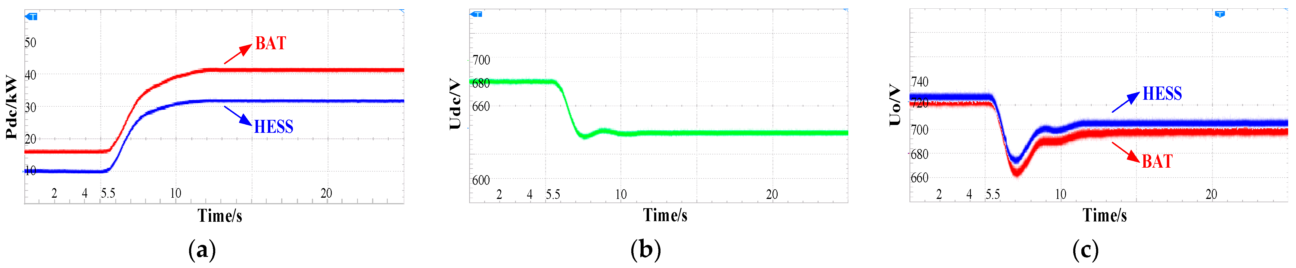
5.2.1. Condition 1: The Output Ratio of Two Energy Storage Modules Is 1:1 (50:50)

Assuming that the output ratio of battery storage and hydrogen storage is 1:1, initially, the load power is 60 kW, the system is stable, and the load power suddenly increases to 100 kW at 5.5 s; the experimental validation results are shown in Figure 13, Figure 14 and Figure 15.
Based on the experimental results, it can be seen that under the joint control of traditional droop control and SMC, the power in Figure 12a cannot be proportionally allocated according to the capacity due to the line resistance. For example, after 5.5 s, the battery energy storage system and the hydrogen energy storage system each provide 32.5 kW and 42 kW of power, and at the same time, the DC bus voltage stabilizes at 630 V after fluctuation, which cannot be maintained at the rated value. Under the joint control of traditional droop control and the SMC-based improved exponential reaching law, as shown in Figure 14b, the DC bus voltage fails to remain at the rated value, although it increases to 642 V. Under the control strategy proposed in this paper, after the load power increases to 100 kW, the battery storage system and the hydrogen storage system each provide 50 kW of power; at the same time, the DC bus voltage remains at the rated value, and the output voltage of each DG correspondingly increases to meet the load demand, as shown in Figure 15c.

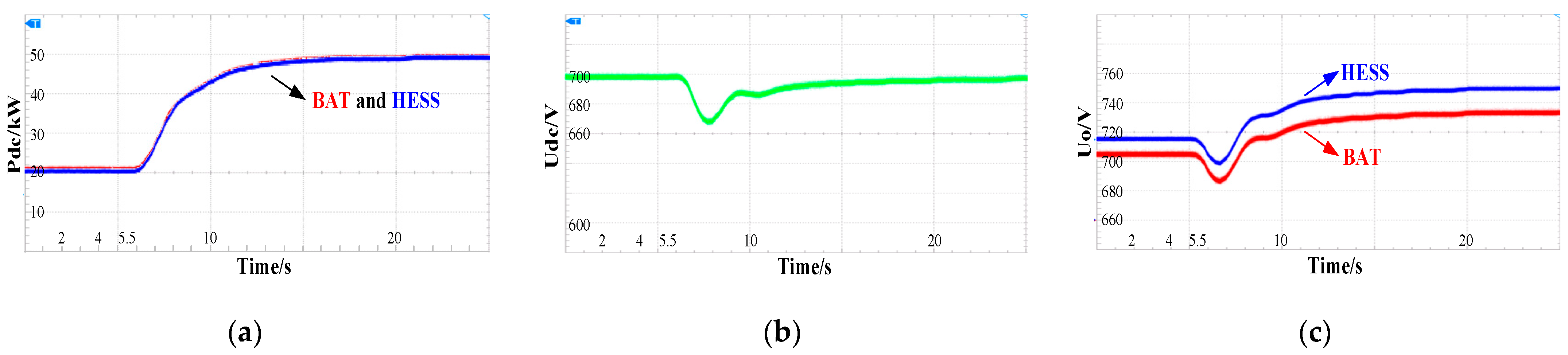
5.2.2. Condition 2: The Output Ratio of Two Energy Storage Modules Is 3:2 (60:40)

Assuming that the power ratio of battery storage and hydrogen storage is 3:2, initially, the load power is 90 kW, the system is stable, and at 5.5 s, the load power suddenly reduces to 50 kW; the experimental verification results are shown in Figure 16, Figure 17 and Figure 18.
After further experimental verification, when the load power suddenly reduces and the output ratio of the two storage modules is 3:2, under the control strategy proposed in this paper, the power ratios of the battery storage system and the hydrogen storage system are proportionally allocated, the DC bus voltage increases and then maintains at the rated value, and the output voltages of the DGs change accordingly to meet the load demand.

6. Conclusions

In order to improve the control performance of the DC microgrid system, an SMC strategy based on an improved exponential reaching law for a single bidirectional DC/DC converter is proposed in this paper. By revising the constant-speed reaching term and introducing system state variables to describe the chattering level, the dynamic performance of the bidirectional DC/DC converter improves while the chattering problem is effectively suppressed. In addition, an improved droop control strategy—considering the line impedance characteristics of the parallel bidirectional DC/DC converters group—is proposed. By adding a virtual resistor to revise the traditional droop control and introducing the voltage information of the DC bus instead of the line impedance value, both the power allocation of the parallel bidirectional DC/DC converter group and the stability of the DC bus voltage can be enhanced. This approach reduces the system’s reliance on communication and guarantees the function of plug-and-play distributed generation. Finally, the stability of the two control strategies is verified individually. Then, they are combined and applied to the control of the parallel bidirectional DC/DC converters group. The StarSim hardware-in-the-loop experimental platform was utilized to carry out the experimental verification. Comparison results show that under the same experimental conditions, the control strategy proposed in this paper not only ensures the optimal power allocation accuracy but also maintains the stability of the DC bus voltage at the fastest speed when the load is disturbed and suddenly changes, demonstrating the feasibility and effectiveness of the proposed control strategies.

Author Contributions

Conceptualization, W.L. and J.J.; methodology, W.L.; software, W.L. and H.D.; validation, W.L., J.J. and H.D.; formal analysis, M.H.; investigation, S.H.; resources, M.H.; data curation, W.L. and M.H.; writing—original draft preparation, H.D.; writing—review and editing, W.L.; supervision, J.J.; funding acquisition, H.D. All authors have read and agreed to the published version of the manuscript.

Funding

The project is sponsored by “Liaoning BaiQianWan Talents Program” (LNBQW2020-18).

Data Availability Statement

The data is unavailable due to privacy or ethical restrictions.

Conflicts of Interest

Authors Henan Dong and Shubo Hu are employed by State Grid Liaoning Electric Power Co., Ltd., and Miao He is employed by State Grid Liaoyang Power Supply Company, to whom without conflict of interest related to the present study. The remaining authors declare that the research was conducted in the absence of any commercial or financial relationships that could be construed as a potential conflict of interest.

References

  1. Liu, J.; Han, X.; Wang, L.; Peng, Z.; Jing, W. Operation and control strategy of DC Microgrid. Power Syst. Technol. 2014, 38, 2356–2362. [Google Scholar]
  2. Rui, L.; Maksimovic, D.; Leyva, R. Second-order sliding mode controlled synchronous buck DC-DC converter. IEEE Trans. Power Electron. 2016, 31, 2539–2549. [Google Scholar]
  3. Ni, Y.; Xu, J. Analysis of Quasi-sliding-mode switching control for DC-DC converters. Chin. J. Electr. Eng. (Proc. CSEE) 2008, 28, 1–6. [Google Scholar]
  4. Agarwal, A.; Deekshitha, K.; Singh, S.; Fulwani, D. Sliding mode control of a bidirectional DC-DC converter with constant power load. In Proceedings of the IEEE First International Conference on DC Microgrids, Atlanta, GA, USA, 7–10 June 2015; pp. 287–292. [Google Scholar]
  5. Andrzej, B.; Pawet, L. Discrete time sliding mode control with reduced switching-Anew reaching law approach. Int. J. Robust Nonlinear Control 2016, 26, 47–68. [Google Scholar]
  6. Tarchata, G. Sliding Mode Speed Control of an Induction Motor Drive Using Time-Varying Switching Line. Power Electron. Drives 2017, 2, 105–120. [Google Scholar]
  7. Zhang, X.G.; Zhao, K.; Sun, L.; An, Q.T. Novel convergence rate control for sliding mode variable structure speed control system of permanent magnet synchronous motor. Chin. J. Electr. Eng. 2011, 31, 77–82. [Google Scholar]
  8. OscarIvan, H.M.; Mauricio, S.J.; Hernando, D.M. Discrete-time variable structure control for switching converters. In Proceedings of the IEEE/PES Transmission and Distribution Conference and Exposition, Denver, CO, USA, 16–19 April 2018. [Google Scholar]
  9. Sharma, N.K.; Janardhanan, S. A Novel Second-order Recursive Reaching Law based Discrete-time Sliding Mode Control. IFAC Pap. Online 2016, 49, 225–229. [Google Scholar] [CrossRef]
  10. Dai, P.; Xu, N.; Xie, H.; Lv, Y. Fast power convergence law control of permanent magnet synchronous motor speed control system. J. Electr. Mach. Control 2017, 21, 32–38. [Google Scholar]
  11. Li, Z.; Hu, G.; Cui, J.; Liu, G. Integral sliding mode variable structure control of permanent magnet synchronous motor speed control system. Chin. J. Electr. Eng. 2014, 34, 431–437. [Google Scholar]
  12. Bai, C.; Yin, Z.; Liu, J.; Zhang, Y.; Sun, X. Integrated Sliding Mode Velocity Control of Linear Permanent Magnet Synchronous Motor with Thrust Ripple Compensation. CES Trans. Electr. Mach. Syst. 2023, 7, 100–109. [Google Scholar] [CrossRef]
  13. Wang, C.; Li, W.; Wang, Y.; Meng, Z.; Yang, L. DC bus voltage fluctuation classification and restraint methods review for DC microgrid. Proc. CSEE 2017, 37, 84–98. [Google Scholar]
  14. Tsikalakidroop, H. Centralized Contml for Optimizing Microgrids Operation. IEEE Trans. Energy Convers. 2008, 23, 1–8. [Google Scholar]
  15. Zhang, G.; Ding, X.; Peng, B.; Xie, R.S.; Bi, K.J. Improved control strategy for an AC/DC hybrid microgrid interlinking converter. Power Syst. Prot. Control 2020, 48, 50–58. [Google Scholar]
  16. Yang, J.; Jin, X.; Wu, X.; Jiang, C. An improved load current sharing control method in DC microgrids. Proc. CSEE 2016, 36, 59–67. [Google Scholar]
  17. Lu, X.; Guerrero, J.M.; Sun, K.; Vasquez, J.C. An improved droop control method for DC microgrids based on low band width communication with DC bus voltage restoration and enhanced current sharing accuracy. IEEE Trans. Power Electron. 2013, 29, 1800–1812. [Google Scholar] [CrossRef]
  18. Wang, P.; Lu, X.; Yang, X.; Wang, W.; Xu, D. An improved distributed secondary control method for DC microgrids with enhanced dynamic current sharing performance. IEEE Trans. Power Electron. 2016, 31, 6658–6673. [Google Scholar] [CrossRef]
  19. Liu, Z.; Miao, S.; Fan, Z.; Kong, Y. Accurate power allocation and zerosteady-state error voltage control of the islanding DC microgird based on adaptive droop characteristics. Trans. China Electrotech. Soc. 2019, 34, 795–806. [Google Scholar]
  20. Khorsandi, A.; Ashourloo, M.; Mokhtari, H.; Iravani, R. Automatic droop control for a low voltage DC microgrid. IET Gener. Transm. Distrib. 2015, 10, 41–47. [Google Scholar] [CrossRef]
  21. Tah, A.; Das, D. An enhanced droop control method for accurate load sharing and voltage improvement of isolated and interconnected DC microgrids. IEEE Trans. Sustain. Energy 2016, 7, 1194–1204. [Google Scholar] [CrossRef]
  22. Kan, C.Z.; Chen, Y.F.; Li, P.C.; Zhang, C.J. Research on current load dynamic allocation method for distributed energy storage system. Power Electron. Technol. 2016, 50, 113–117. [Google Scholar]
  23. Yang, J.; Jin, X.; Wu, X.; Acuna, P.; Aguilera, R.P.; Morstyn, T.; Agelidis, V.G. Decentralized control method for DC microgrids with improved current sharing accuracy. IET Gener. Transm. Distrib. 2017, 11, 696–706. [Google Scholar] [CrossRef]
  24. Zhang, W.F.; Zhang, J.B.; Li, C.S. Semi-physical simulation study of grid-connected control of photovoltaic power generation system based on StarSim. Electr. Switchg. 2021, 59, 66–68. [Google Scholar]
Figure 1. The functional diagram of the DC microgrid.
Energies 17 04628 g001
Figure 2. Equivalent structure of the DC microgrid system.
Energies 17 04628 g002
Figure 3. SMC structure based on the improved exponential reaching law.
Energies 17 04628 g003
Figure 4. Comparison of sliding mode motion under two exponential reaching laws, (a) exponential reaching law; (b) improved exponential reaching law.
Energies 17 04628 g004
Figure 5. Simplified equivalent diagram of the DC microgrid system.
Energies 17 04628 g005
Figure 6. Analysis of traditional and improved droop control, (a) limitation of the traditional method; (b) feasibility of the improved method.
Energies 17 04628 g006
Figure 7. Schematic diagram of the improved droop control.
Energies 17 04628 g007
Figure 8. Simplified control structure of two DC/DC converters.
Energies 17 04628 g008
Figure 9. Root locus diagram for variable parameters, (a) ω c = 500   r a d / s , R d , i ( j ) ; (b) R d , i ( j ) = 0.6   Ω , ω c .
Energies 17 04628 g009
Figure 10. StarSim hardware-in-the-loop experiment platform, (a) the experimental environment; (b) backside wiring.
Energies 17 04628 g010
Figure 11. Comparison of DC bus voltage start waveforms.
Energies 17 04628 g011
Figure 12. Comparison of DC bus voltage waveforms, (a) PI; (b) SMC; (c) improved SMC.
Energies 17 04628 g012
Figure 13. Traditional droop control + SMC under condition 1, (a) DG output power; (b) DC bus voltage; (c) DG output voltage.
Energies 17 04628 g013
Figure 14. Traditional droop control + improved SMC under condition 1, (a) DG output power; (b) DC bus voltage; (c) DG output voltage.
Energies 17 04628 g014
Figure 15. Improved droop control + improved SMC under condition 1, (a) DG output power; (b) DC bus voltage; (c) DG output voltage.
Energies 17 04628 g015
Figure 16. Traditional droop control + SMC under condition 2, (a) DG output power; (b) DC bus voltage; (c) DG output voltage.
Energies 17 04628 g016
Figure 17. Traditional droop control + improved SMC under condition 2, (a) DG output power; (b) DC bus voltage; (c) DG output voltage.
Energies 17 04628 g017
Figure 18. Improved droop control + improved SMC under condition 2, (a) DG output power; (b) DC bus voltage; (c) DG output voltage.
Energies 17 04628 g018
Table 1. The advantages and disadvantages of the methods proposed by other authors.
Control StrategyReferencesAdvantagesDisadvantages
SMC[2]Simplified the design of the second-order sliding mode controller.Reduced the system’s anti-interference ability and robustness.
[3]Shortened the sliding mode arrival time and improved the dynamic performance.Chattering problems.
[4]Enhanced the system’s robustness.Increased control difficulty; the high-frequency chattering phenomenon could not be solved completely.
[5,6,7,8]Further improved control strategies.Failed to achieve complete suppression and increased the control complexity.
[9,10,11,12]Proposed a new sliding mode reaching law. Output voltage ripple increased and the chattering problem persisted as before.
Droop control[13,14,15]The control method was simplified without considering the impact of line impedance.Led to unreasonable power allocation and common bus voltage deviation.
[16]Reduced the voltage deviation.Power allocation accuracy was bad.
[17,18]Improved the power allocation accuracy.The common bus voltage deviation was not reduced.
[19]Collected the common bus voltage directly.The transmission pressure increased.
[20,21,22]Weakened the influence of line impedance on power allocation.Power allocation accuracy was still bad.
Table 2. Parameters for system stability analysis.
ParametersValueParametersValue
ω c / ( r a d / s ) 20–1000 R l o a d / Ω 150
R l i n e , i / Ω 1.5 R d , i / Ω 0.1–5
R l i n e , j / Ω 1 R d , j / Ω 0.1–5
Table 3. Experimental parameters.
ParametersValueParametersValue
ω c / ( r a d / s ) 500 u d c r e f / V 700
R L B / Ω 1.5 R L H / Ω 0.6
L B / m L 2.5 L H / m L 3.0
C B / m F 0.5 C H / m F 0.8
R d , i / Ω 1.2 R d , j / Ω 0.4
Disclaimer/Publisher’s Note: The statements, opinions and data contained in all publications are solely those of the individual author(s) and contributor(s) and not of MDPI and/or the editor(s). MDPI and/or the editor(s) disclaim responsibility for any injury to people or property resulting from any ideas, methods, instructions or products referred to in the content.

