Article

Multi-Objective Optimization Analysis of Electromagnetic Performance of Permanent Magnet Synchronous Motors Based on the PSO Algorithm

by
Yufei Cen
1,
Haoyu Shen
2,
Xiaoyuan Wang
2,
Yongming Wu
3 and
Jingjuan Du
4,*
1
School of Construction Machinery, Chang’an University, Xi’an 710064, China
2
School of Electrical and Information Engineering, Tianjin University, Tianjin 300072, China
3
Leadrive Technology (Liuzhou) Co., Ltd., Liuzhou 545000, China
4
School of Control and Mechanical Engineering, Tianjin Chengjian University, Tianjin 300384, China
*
Author to whom correspondence should be addressed.
Energies 2024, 17(18), 4637; https://doi.org/10.3390/en17184637
Submission received: 24 August 2024 / Revised: 10 September 2024 / Accepted: 11 September 2024 / Published: 17 September 2024
(This article belongs to the Section F: Electrical Engineering)

Abstract

:
In order to optimize the electromagnetic performance of a permanent magnet synchronous motor (PMSM) during operation, this paper takes the size of the stator slot structure of the motor as the optimization variable and the peak cogging torque and no-load back electromotive force (EMF) amplitude of the motor as the optimization objectives. A multi-objective optimization method based on the particle swarm optimization (PSO) algorithm is adopted to obtain a structural parameter combination that minimizes the peak cogging torque and no-load back EMF amplitude while meeting the reasonable range requirements of magnetic flux density amplitude. The optimized motor structure design prototype is experimentally verified. The results show that through multi-objective optimization based on the PSO algorithm, the electromagnetic performance of the motor has been improved, with a reduction of 36.33% in peak cogging torque and 2.65% in peak no-load back EMF, indicating a reasonable magnetic flux density amplitude. The experimental results of the optimized prototype show that the difference between the theoretical simulation values and the experimental values is within a reasonable range, which verifies the effectiveness of the multi-objective optimization method.

1. Introduction

Permanent magnet synchronous motors (PMSMs) are widely utilized in electric vehicle systems due to their superior characteristics, such as excellent speed regulation, high power density, high efficiency, simple structure, and superior servo performance [1,2]. During high-speed no-load operation, cogging torque causes torque fluctuations, resulting in vibration noise. Excessive back electromotive force (EMF) can also diminish the motor’s flux-weakening and speed expansion ability, and even damage the inverter. Therefore, optimizing the electromagnetic performance of PMSMs involves reducing both cogging torque and no-load back EMF to mitigate vibration noise and enhance the motor’s flux-weakening and speed expansion capabilities during high-speed operation.
The electromagnetic performance of PMSMs is primarily optimized by adjusting the structural dimensions of the stator and rotor. Reference [3] enhances motor electromagnetic performance by introducing auxiliary slots in the stator teeth to reduce cogging torque. Reference [4] improves electromagnetic performance by optimizing the radius and angle of rotor slots to minimize cogging torque. Reference [5] minimizes specific harmonic components of cogging torque by optimizing the fit between the stator and rotor slots and adjusting the permanent magnet (PM) width to minimize total harmonic components, thereby achieving optimal motor electromagnetic performance. Reference [6] proposes an optimization design method of air flux barrier to reduce torque fluctuations in PM motors, thereby enhancing electromagnetic performance.
In addition to improving motor structural dimensions, multi-objective optimization strategies are crucial for enhancing motor electromagnetic performance. Reference [7] employs the Taguchi optimization algorithm to optimize the electromagnetic design of PMSMs by varying rotor magnet arc coefficient, magnet steel thickness, and air-gap length. Reference [8] targets motor-rated torque, torque ripple, iron loss, and flux density as optimization objectives, optimizing stator outer diameter, air-gap length, and magnet steel outer diameter using an improved Taguchi iterative algorithm to enhance motor performance. Reference [9] adopts a hierarchical optimization strategy targeting cogging torque and no-load back EMF waveform distortion to perform multi-objective optimization design on the motor. Reference [10] utilizes the response surface method for multi-objective optimization design of torque and efficiency in PM motors to reduce torque ripple and enhance motor performance. Reference [11] uses the BP neural network and genetic algorithm to optimize the optimal combination of slot width and main magnetic pole ratio to improve motor performance. Reference [12] targets torque density, flux-weakening ability, and rotor strength, employing the cuckoo search algorithm for optimal motor design to enhance performance.
The optimization algorithms mentioned in the above literature have some defects with respect to optimizing motor structure, such as the following: in the Taguchi iterative method compared to the particle swarm optimization (PSO) algorithm, global optimization is poor and falls easily into local optimization; the hierarchical optimization strategy requires a complex layering design and is less flexible; the response surface method in the optimization process requires a larger number of sample points and the computational efficiency is low; genetic algorithms have more parameter settings and the speed of convergence is slower; the cuckoo bird algorithm search mechanism is more complex and stability is poor. Therefore, with respect to the defects of the optimization algorithms commonly used to optimize the electromagnetic performance of a motor, this paper proposes an optimization strategy based on the PSO algorithm. Although the PSO algorithm is more common, it has the advantages of a strong global search capability, adaptive, high computational efficiency, few parameters, fast convergence, is simple and direct, and so on, and it can make up for the defects of the above-mentioned optimization algorithms in terms of optimizing the electromagnetic performance of the motor.
The multi-objective optimization strategy based on the PSO algorithm not only plays a role in optimizing the structural parameters of the motor to improve the no-load performance but also plays an important role in reducing the harmonic content of the magnetic field as well as optimizing the control strategy of the motor.
The stator and rotor structure dimensions and air-gap length of the motor have an important impact on motor performance, but the rotor structure in the optimization process involves dynamic equilibrium and mechanical strength and other real factors that need to be taken into account, which increases the complexity of the optimization project. Therefore, taking into account the importance of the structure, the difficulty of structural optimization, and motor operating conditions, this paper aims to optimize the stator dimensions and the length of the air gap of the motor by using the PSO multi-objective optimization algorithm to improve the performance of the motor. Firstly, electromagnetic field analysis of the motor is conducted to determine various performance metrics under rated no-load conditions. Secondly, a parametric model of the motor structure is developed to identify critical structural parameters for optimization. Parameter sensitivity analysis enhances model accuracy by identifying highly sensitive parameters. Utilizing the PSO algorithm for multi-objective optimization, optimal combinations of structural parameters are identified to maximize motor electromagnetic performance. A comparative analysis of motor electromagnetic performance before and after optimization is performed. Finally, an experimental prototype of the optimized motor structure is designed to validate the effectiveness of this multi-objective optimization strategy.

2. Electromagnetic Field Analysis of PMSM

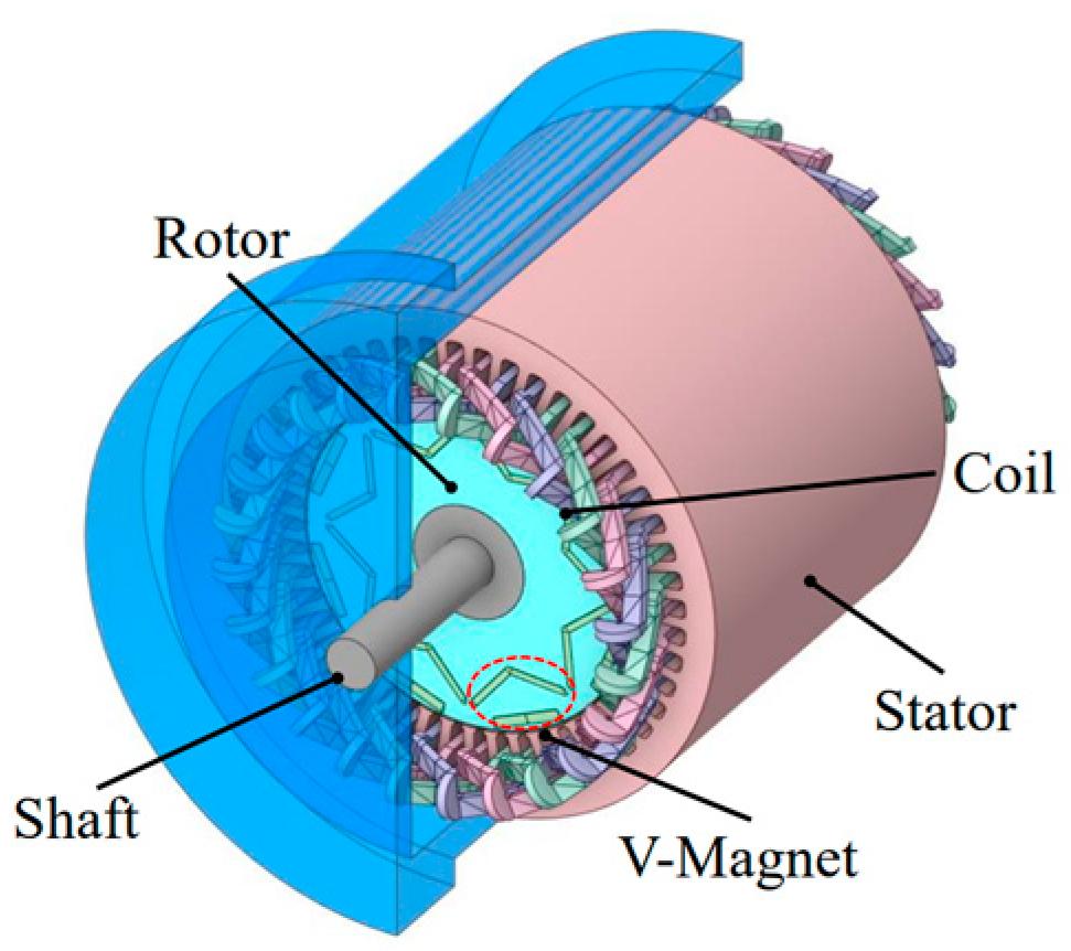
2.1. Structure and Parameters

The structure of the PMSM selected in this study is shown in Figure 1. The motor has a V-type PM structure, and the main parameters are detailed in Table 1.

2.2. Rated No-Load Electromagnetic Calculation

The no-load back EMF is induced in the armature windings by the fundamental magnetic flux produced by the PMs in the air gap. It significantly affects the dynamic and steady-state performance of the motor and determines whether the motor operates in a magnetizing or demagnetizing state. This parameter is crucial for evaluating the electromagnetic performance of the motor and is expressed as follows:
E 0 = 2 π K dp f N ϕ
where E0 is the rms value of the no-load back EMF per phase, Kdp is the winding factor, f is the frequency, N is the number of turns per phase, and ϕ is the flux per pole.
During the rated no-load operation of the PMSM, the tangential component of the interaction force between the PMs and stator teeth fluctuates, generating cogging torque. Cogging torque induces torque ripple in the PMSM, leading to speed fluctuations. Torque ripple also causes vibration and noise, impacting motor performance. The expression is given as follows [4]:
T cog = W α
W = 1 2 L i 2 + 1 2 ( R + R m ) ϕ m 2 + N i ϕ m
B ( θ , α ) = B r ( θ ) h m ( θ ) h m ( θ ) + δ ( θ , α )
T cog ( α ) = π z L a 4 μ 0 ( R 2 2 R 1 2 ) n = 1 n G n B r nz 2 p sin nZ α
where Tcog is the cogging torque, W is the magnetic field energy, and α is the relative angular position between the stator and rotor; L is the self-inductance of windings, i is the phase current of windings, N is the number of turns per phase, R is the air-gap reluctance, Rm is the stator core reluctance, and ϕ m is the PM flux; B(θ,α) is the magnetic flux density distribution along the armature surface, and Br(θ), δ(θ), and hm(θ) are, respectively, residual magnetism of the PM, effective air-gap length, and the distribution of magnetization length of the PM along the circumference; Tcog(α) is the mathematical analytical expression of cogging torque obtained by Fourier series expansion of residual magnetism magnetic flux density Br(θ) and effective air-gap length δ(θ,α), z is the total number of stator slots, La is the axial length of the armature core, μ0 is the vacuum permeability, R2 is the inner radius of stator yoke, R1 is the outer radius of the armature, n is an integer that makes nz/2p an integer, Br is the residual magnetism of PM, and Z is the minimum common multiple of stator slots and poles.

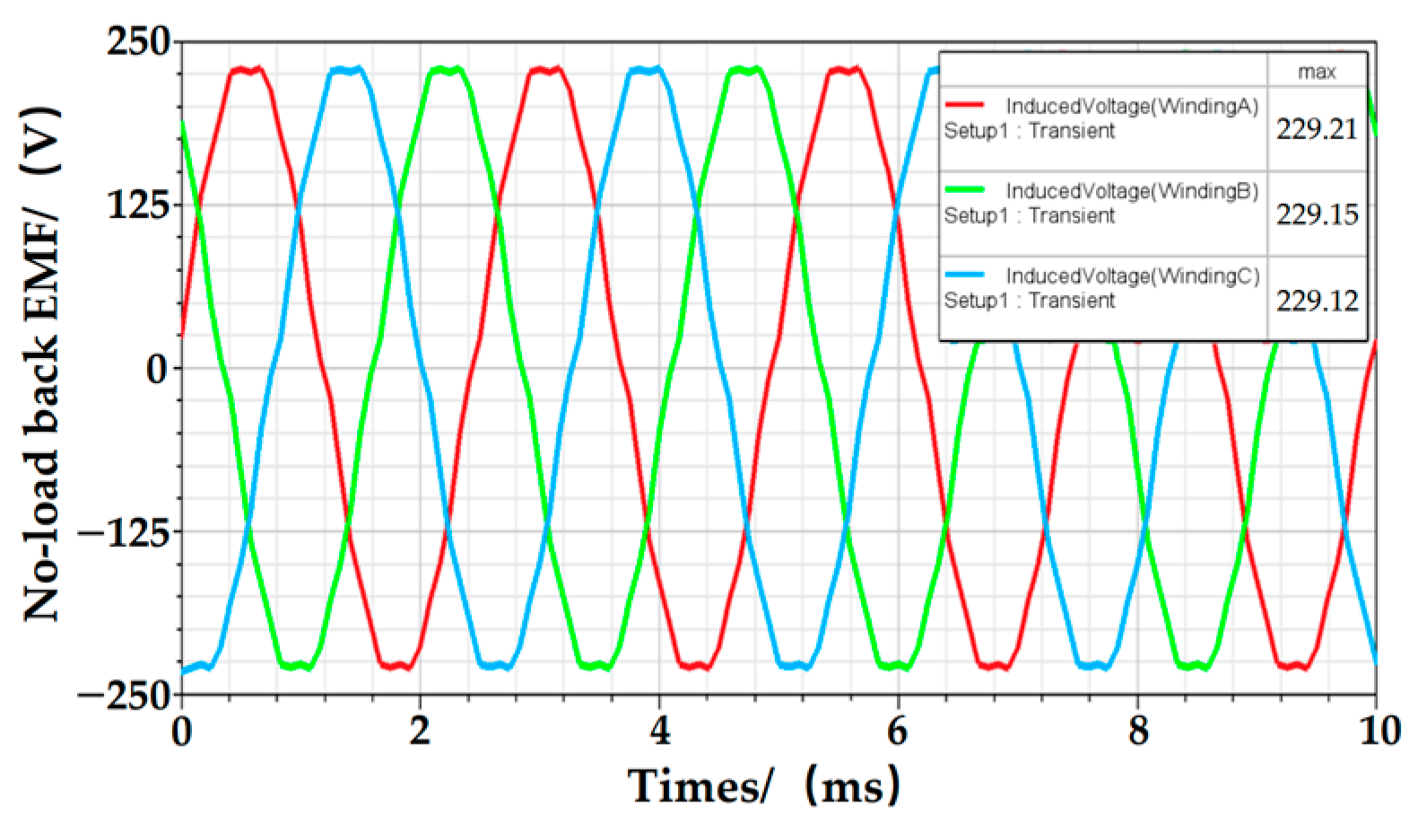
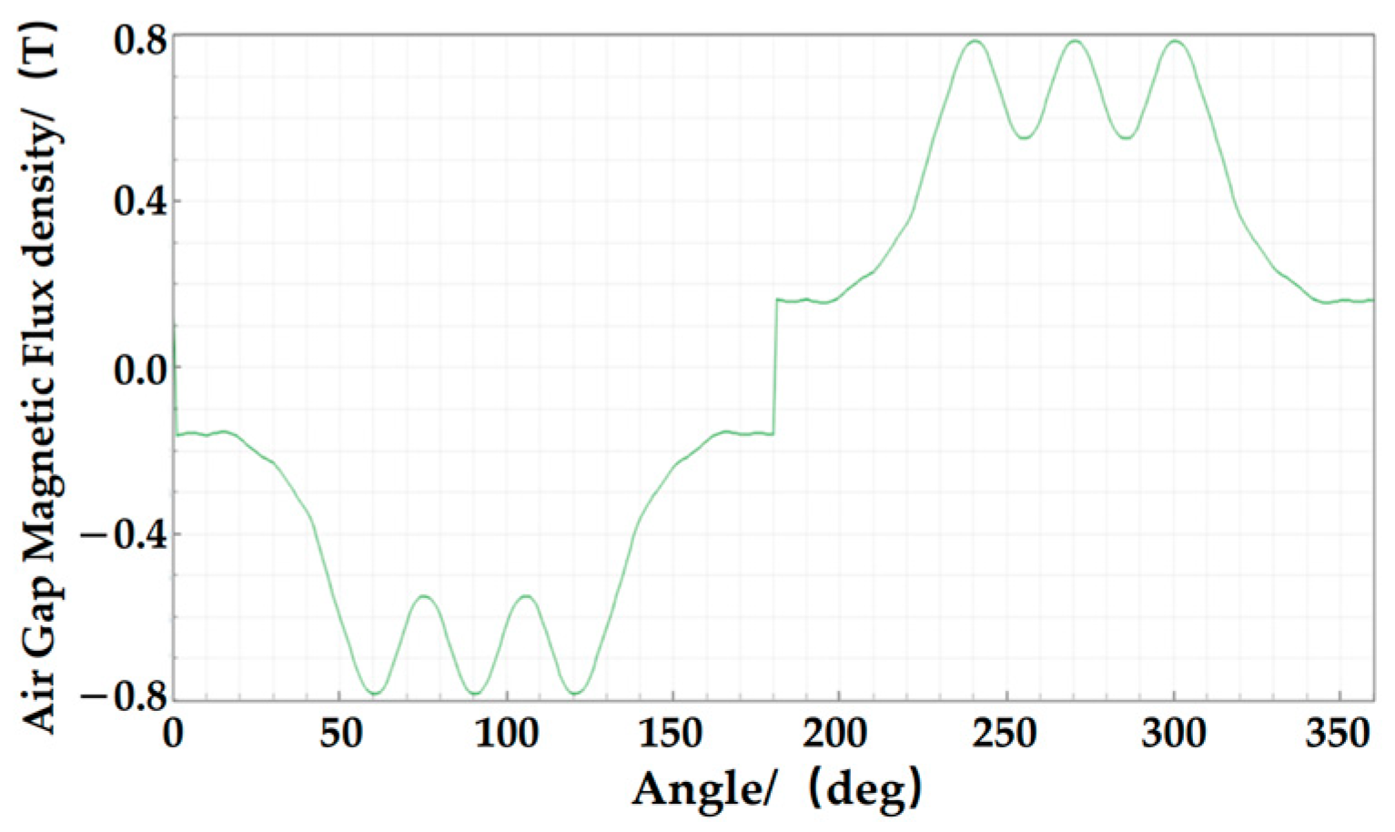
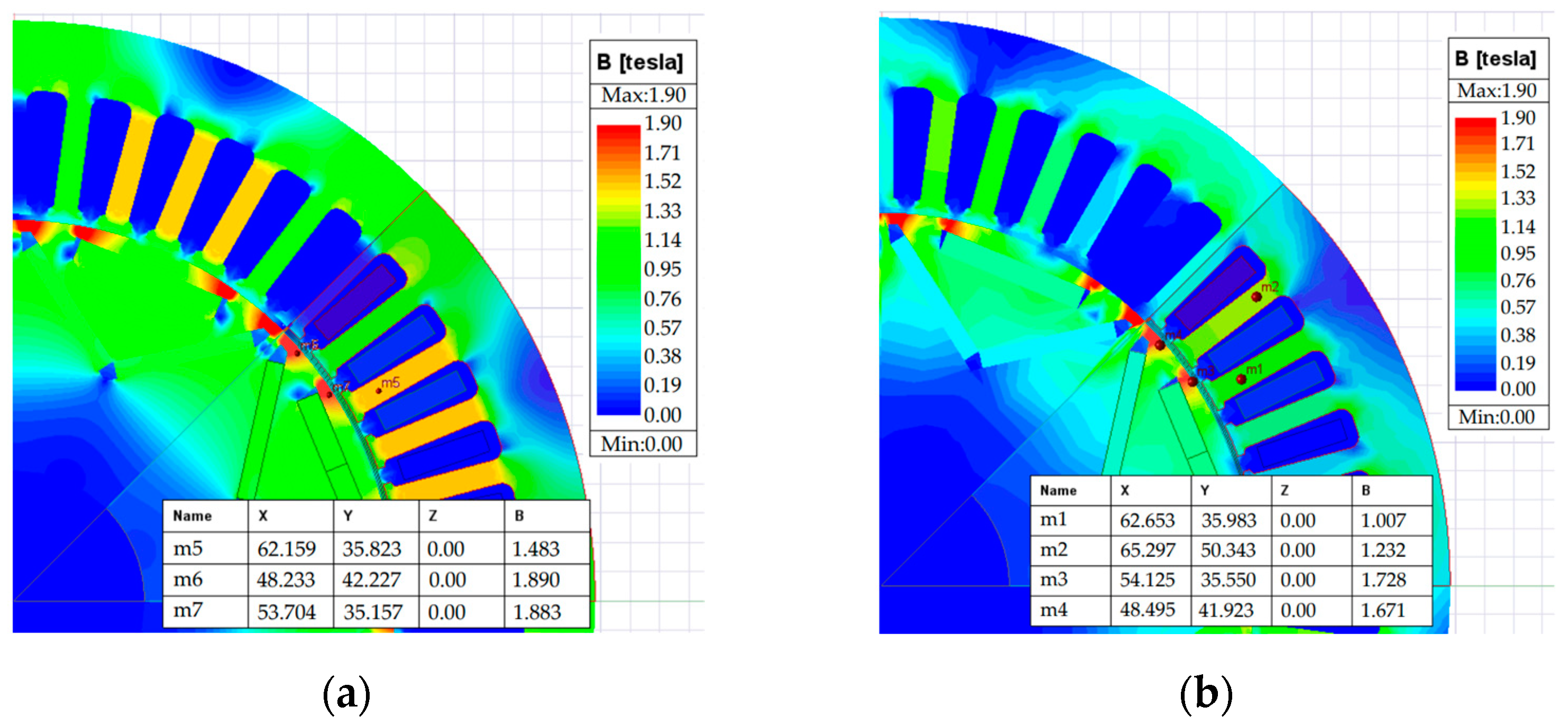
2.3. Rated No-Load Electromagnetic Field Simulation

In order to investigate the no-load electromagnetic performance of the PMSM designed in this paper, an electromagnetic field analysis based on Ansys Electronics Desktop for the rated no-load case will be carried out, and the corresponding results of no-load back EMF, cogging torque, and no-load magnetic density will be produced.
The waveform of the back EMF under motor no-load conditions is shown in Figure 2. The figure shows that the peak value of the no-load back EMF is approximately 230 V. Excessive no-load back EMF can diminish the motor’s flux-weakening and speed expansion ability, even damaging the inverter. Therefore, optimizing the motor’s performance design should minimize the peak value of the no-load back EMF.
The cogging torque waveform of the motor is shown in Figure 3. This waveform completes one cycle of torque fluctuation per stator slot pitch angle. The figure indicates that the peak cogging torque is approximately 0.479 N·m. Higher cogging torque levels can cause periodic torque pulsations during high-speed motor operation, resulting in increased vibration noise and additional energy consumption, thus reducing motor efficiency. Therefore, optimizing motor performance should minimize peak cogging torque values as much as possible.
The air-gap magnetic flux density waveform and magnetic flux density distribution cloud map of the motor are illustrated in Figure 4 and Figure 5, respectively. In Figure 4, the amplitude of the motor air-gap magnetism is 0.788 T. Under the motor specifications designed in this paper, the value of the air-gap magnetism is within a reasonable range, which is conducive to reducing the magnetic imbalance and torque fluctuations, lowering the vibration noise generated by the motor operation, and improving the smoothness and comfort of the motor operation. In Figure 5, the highest magnetic density value of the stator yoke is 1.48 T, while the magnetic density at the rotor spacer bridge reaches 1.87 T. This magnetic density value is high compared to that of the silicon steel used in the PMSM of new energy vehicles. Such high magnetic density can lead to increased iron losses and complicate cooling and heat dissipation. Therefore, it is important to optimize the stator slot structure and adjust the air gap length to effectively reduce the magnetic density amplitude.

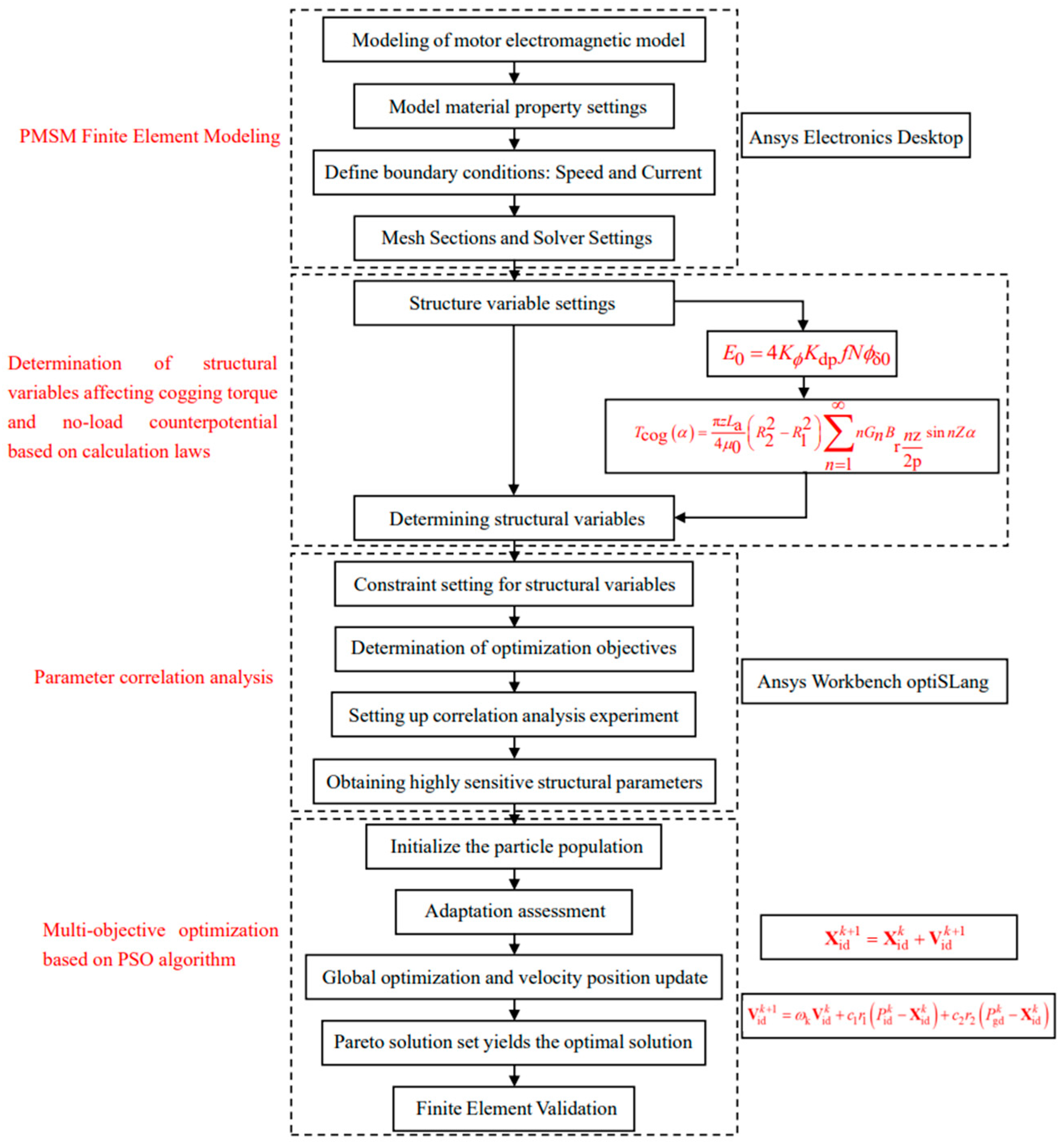
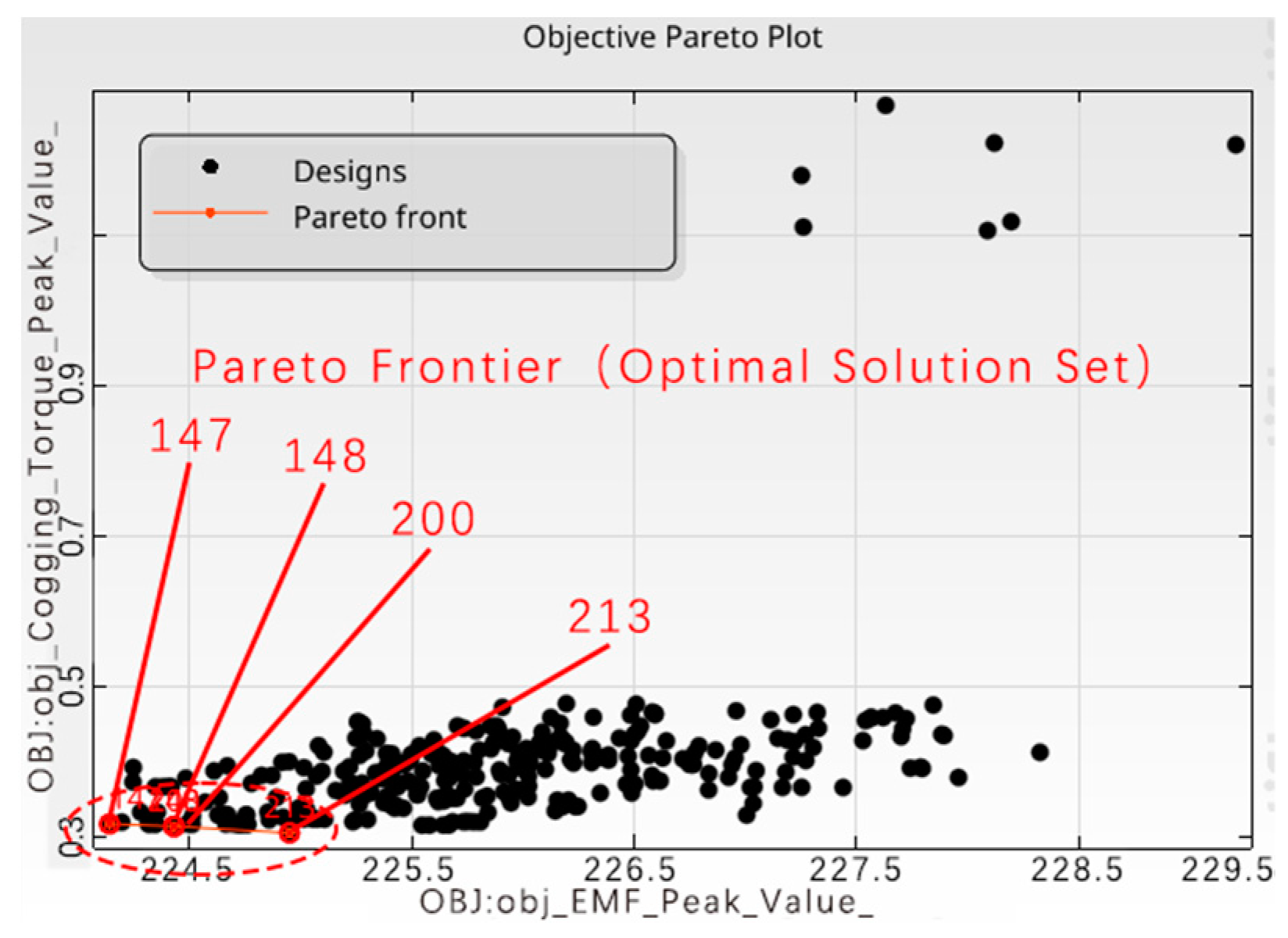
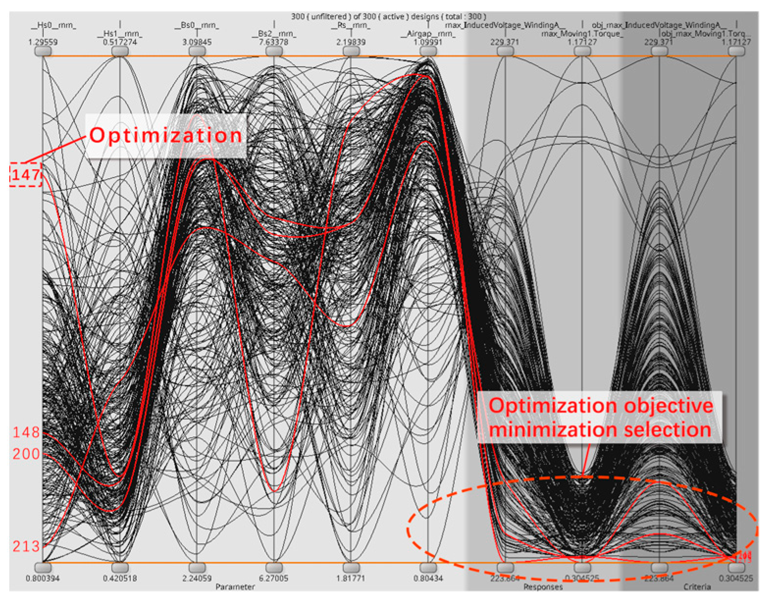
3. Multi-Objective Optimization Based on the PSO Algorithm

3.1. Structural Parameterized Model

In this paper, the PSO multi-objective optimization algorithm is used to optimize the stator slot size and air-gap length of the motor to improve the performance of the motor. The optimization structure of the PSO algorithm is based on continuously updating the speed and position of the particles. The particle swarm explores different combinations of the stator slot size and air-gap length in the search space and gradually approaches the optimal solution, so as to arrive at the global optimal solution of the structural parameters. The specific optimization process is shown in Figure 6 below:
This paper focuses on the multi-objective optimization design of the stator structure dimensions of the motor. The eight structural parameters of stator slot structure and air-gap length are selected as optimization variables. The reason for this selection is that these structural parameters have a greater impact on the motor’s electromagnetic performance. By optimizing the stator slot structure, magnetic energy utilization can be improved, reducing the harmonic content in the magnetic field and electromotive force and lowering the no-load loss; optimizing the air-gap length helps to reduce the torque pulsation and improve the smoothness of the motor operation. The parametric model of the structure is illustrated in Figure 7, and Table 2 shows the ranges of the optimization variables.
For the selection of the parameter range of the stator slot structure, it is necessary to follow the principle of magnetic circuit saturation; consider the slot fullness and slot leakage reactance to satisfy the effective conduction of the magnetic flux; realize the good rated electromagnetic energy conversion; as well as to ensure the equilibrium between the electromagnetic performance of the motor and the slot leakage reactance. For the selection of the parameter range of the air-gap length, it is necessary to consider transmission of electromagnetic force, harmonics, and mechanical assembly in the actual production. The problem of electromagnetic force transmission, harmonics, mechanical assembly, and manufacturing precision in actual production should be considered. In this paper, the principle of range selection is made for the selection of the range in Table 2.
Based on electromagnetic field analysis under rated conditions and ensuring that the peak magnetic flux density Bmax falls within a reasonable range, the peak no-load back EMF E0_max and peak cogging torque Tcog_max are chosen as objectives for minimization.

3.2. Construction of the Optimization Function

Due to the large number of structural parameters requiring optimization, which results in a large sample size for multi-objective optimization and consequently affects the optimization results, sensitivity analysis of these structural variables is necessary. In this paper, an Adaptive Latin Hypercube Sampling (ALHS) method is employed for sampling, and a series of experiments is designed based on the Design of Experiments (DOE) method to obtain correlation values between parameter variables and optimization objectives. Sensitivity analysis based on Sobol indices decomposes the objective function into sums of different sub-functions [13]:
f ( x ) = f 0 + i = 1 n f i ( x i ) + 1 i < j n f ( x i , x j ) + + f 1 , 2 , , n ( x 1 , x 2 , , x n )
where x is the structural parameter variables and f0 is the constant.
Based on the variance of each term in the equation, sensitivities of multiple structural variables to the objective function are determined [13]:
S T i = D t D i D t
where STi is the global sensitivity of structural parameter variable xi, Dt is the total variance of f(x), and Di is the total variance of the remaining terms.
According to the impact of each optimization objective on the electromagnetic performance, weights are assigned accordingly, and expressed mathematically as [14]:
f ( x 1 , x 2 , ) = i = 1 n λ i U 0 U min U max U min
where f is the fitness, x1, x2, …, and xn are the highly sensitive structural parameter variables, λi is the corresponding weight for each objective, and U0, Umax, and Umin denote random values, maximum values, and minimum values of optimization objectives under the structural parameter combination.
The optimization objectives of this study aim to achieve a higher effective rated electromagnetic torque, minimal rated output torque ripple, and minimal mean iron core loss. Therefore, the motor optimization problem is ultimately transformed into minimizing the objective function, specifically:
F ( x ) = λ 1 E 0 _ max E 0 _ min E 0 E 0 _ min + λ 2 T cog T cog _ min T cog _ max T cog _ min

3.3. PSO Algorithm Optimization Model

Figure 8 shows the correlation bar chart between each optimization objective and structural parameter variable. Figure 8a shows that Bs2, Rs, and Airgap significantly influence the peak no-load back EMF. Figure 8b shows that Hs0, Hs1, Bs0, Bs2, Rs, and Airgap largely influence the peak of cogging torque. Therefore, the highly sensitive parameters selected for subsequent multi-objective optimization are Hs0, Hs1, Bs0, Bs2, Rs, and Airgap. According to the respective impacts of each optimization objective on the motor’s electromagnetic performance, the weight coefficients are set to λ1 = 0.4 and λ2 = 0.6.
Performing multi-objective optimization based on the PSO algorithm for the model fitted to highly sensitive parameters and optimization objectives. Based on individual fitness values, the PSO algorithm guides the population towards better regions. Throughout the iteration process, each particle updates its position, computes its fitness value, and compares it with its personal best and the population’s best fitness values to update individual and global best solutions [14]. The velocity and position formulas for particles are as follows [15]:
X id k + 1 = X id k + V id k + 1
V id k + 1 = ω k V id k + c 1 r 1 ( P id k X id k ) + c 2 r 2 ( P gd k X id k )
ω k = ω max - ( ω max - ω min ) k K
where X i d k and X i d k + 1 are the displacement vectors of the i-th particle during its movements in the k-th and k + 1-th iterations, V i d k and V i d k + 1 are the velocity vectors of the i-th particle during its movements in the k-th and k + 1-th iterations, ωk is the inertia weight at the k-th iteration, c1 and c2 are acceleration coefficients, r1 and r2 are two random numbers varying within the range [0,1], P i d k is the individual best position, P g d k is the global best position, ωmax and ωmin are predefined minimum and maximum values, and K is the total number of iterations.
A PSO solution set can be obtained by employing the PSO algorithm for multi-objective optimization, as depicted in Figure 9. The red dot region in the figure represents the optimal solution set combination on the Pareto frontier, derived from a total of four optimal combinations of solutions. From these four optimal solutions, one is selected as the final optimal solution, which is the best result achieved by the optimization strategy.
Figure 10 shows the set of optimal solutions obtained by the algorithm optimization. The red curve in the figure indicates the solutions in the Pareto optimal solution set. Through the curve diagram, we can intuitively select an optimal solution in the optimal solution set, i.e., the 147th solution, which is the solution curve in which the peak value of the peak cogging torque and the peak value of the peak no-load back EMF corresponding to the peak value of the cogging torque and no-load back EMF is the smallest to meet the optimization objective, so that we derive the structural variables and the optimization results for the optimization objective, as shown in Table 3 and Table 4. Through Table 3, we can see that the values of structural parameters Hs0, Hs1, and Bs0 in the stator slot structure are reduced after optimization, while the values of Bs2 and Rs are increased, and the length of the air gap is also increased; through Table 4, we can conclude that, after optimization by the PSO algorithm, there is a significant reduction in the motor cogging torque, with a reduction of 36.33%. There is a certain degree of reduction in no-load back EMF peaks, which puts it within a reasonable range. The electromagnetic performance of the motor is improved, which verifies the effectiveness of the optimization algorithm.
Table 3 compares the motor structural parameters before and after optimization. By applying the optimized structural parameters to the finite element model for electromagnetic field analysis under rated no-load conditions, a comparison of the motor’s electromagnetic performance before and after optimization is presented in Table 4. The results indicate a significant improvement in the motor’s electromagnetic performance after structural optimization, with a reduction of 2.65% in the peak no-load back EMF and 36.33% in the peak cogging torque.
In order to ascertain the veracity of the optimization results, a finite element verification of the optimization results is necessary. The verification results are then compared with the optimization results in order to determine whether the optimization results satisfy the design requirements. Table 5 illustrates the comparison between the optimization results and the finite element verification results. It can be observed that the discrepancy between the two sets of results is minimal and falls within an acceptable range, thereby confirming that the optimization result is accurate and meets the design requirements.
Figure 11 compares the motor’s magnetic flux density performance before and after optimization. Figure 11a,b show the cloud diagrams of the magnetic density distribution before and after the structure optimization, respectively. From the figure, it can be obtained that after the optimization of the stator slot structure size and air-gap length, the maximum magnetization values of the stator and rotor cores are reduced; the highest magnetization value of the stator yoke is reduced from 1.48 T to 1.23 T and the highest magnetization value of the rotor spacer bridge is reduced from 1.87 T to 1.73 T, with a reduction of 16.89% and 7.49%, respectively; and the optimized magnitude of the magnetization is smaller than the saturation flux density of the silicon steel sheet material, which is within a reasonable range. The magnetic density is within a reasonable range, which improves motor performance.

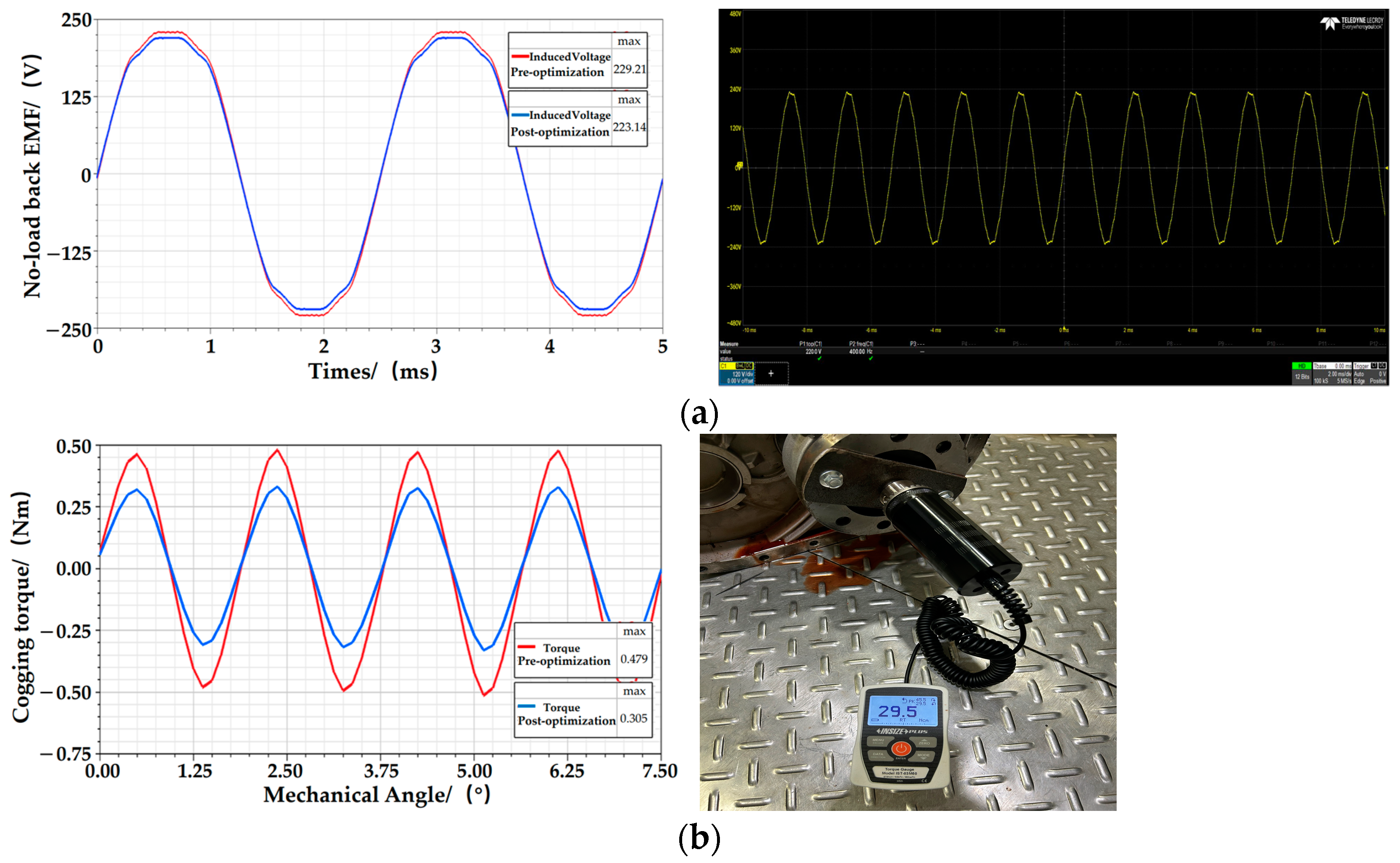
4. Experimental Validation

Experimental tests were conducted on the prototype of the PMSM after structural optimization. The experimental test setup, as shown in Figure 12, included the prototype, a load motor for drag testing, a power meter, an oscilloscope, a controller, and other equipment.
The motor was subjected to no-load performance tests at a rated speed of 3000 r/min. Finite element method (FEM) simulations were used to calculate the no-load electromagnetic performance of the optimized motor, as depicted in Figure 13. Additionally, the experiment measured the no-load back EMF and cogging torque of the motor. From Figure 13a, it can be concluded that the simulation result is 223.14 V and the experimental result is 235.79 V. It can be clearly seen that the difference between the simulation result and the experimental result is small, with an error of 5.36%. From Figure 13b, it can be concluded that the simulation result is 0.305 N·m and the experimental result is 0.295 N·m. The discrepancy between the simulation results and the experimental data is minimal, with an error margin of 3.38%. This demonstrates the accuracy of the optimization results.

5. Conclusions

To enhance the electromagnetic performance of the PMSM, this paper proposes a multi-objective optimization strategy based on the PSO algorithm to optimize the design of the stator slot size and air-gap length of the motor. The conclusions drawn from the research are as follows:
(1)
Significant improvements in the motor’s electromagnetic performance were achieved by globally optimizing the structural parameters using the PSO algorithm-based multi-objective optimization strategy. The peak value of no-load back EMF decreased by 2.65%, and the peak value of cogging torque decreased by 36.33%. Moreover, the magnetic flux density remained within a reasonable range.
(2)
The finite element validation of the results obtained from the optimization strategy was carried out, and it was concluded that the error between the values of the optimization results and the values after the finite element validation was within a reasonable range, thus verifying the reliability of the computational results.
(3)
The experimental tests carried out on the structurally optimized motor show that the experimental values are very close to the theoretical values derived from the simulation, and the errors between the simulated and experimental values for the peak cogging torque and the peak no-load back EMF are 5.36% and 3.38%, respectively, which proves the accuracy of the multi-objective optimization strategy.

Author Contributions

Conceptualization, Y.C. and Y.W.; methodology, Y.C. and J.D.; software, Y.C. and H.S.; validation, Y.C. and Y.W.; formal analysis, Y.C. and X.W.; data curation, Y.C. and J.D.; writing—original draft preparation, Y.C.; writing—review and editing, X.W. and H.S.; supervision, X.W. and J.D. All authors have read and agreed to the published version of the manuscript.

Funding

This research received no external funding.

Data Availability Statement

Data are contained within the article.

Conflicts of Interest

Author Yongming Wu was employed by the company Leadrive Technology (Liuzhou) Co., Ltd. The remaining authors declare that the research was conducted in the absence of any commercial or financial relationships that could be construed as a potential conflict of interest.

References

  1. Zhang, Y.J.; Ye, Q.J.; Zhao, X.C.; Jiang, Z.; Zhu, J.A. Cogging torque reduction method of permanent magnet motor based on optimization of stator structure. Micromotors 2024, 57, 6–9+17. [Google Scholar] [CrossRef]
  2. Jiang, C.; Xue, X.H.; Zhang, L. Electromagnetic optimization design of permanent magnet motor for high-speed train based on torque compensation. Mech. Des. Manuf. Eng. 2022, 51, 74–78. [Google Scholar] [CrossRef]
  3. Gu, H.J.; Huang, W.M.; Wang, C.; Gao, J.W. Influence of stator teeth notching on cogging torque of interior permanent magnet motor. Electr. Mach. Control Appl. 2016, 43, 40–45. [Google Scholar] [CrossRef]
  4. Ye, X.B.; Wu, B.C. Cogging torque optimization design in interior-type permanent magnet synchronous motor. Micromotors 2019, 52, 12–14+51. [Google Scholar] [CrossRef]
  5. Ren, D.J.; Huang, Q.; Li, J.J.; Wu, N. Optimal analysis on cogging torque of the built-in permanent magnet synchronous motors. Explos.-Proof Electr. Mach. 2019, 54, 4–7+43. [Google Scholar] [CrossRef]
  6. Wang, H.M.; Zhong, S.C.; Zhang, W.; Guo, L.Y. Optimal designing of air flux barrier to reduce torque ripple of interior permanent magnet synchronous motor. Micromotors 2021, 54, 18–22. [Google Scholar] [CrossRef]
  7. Qiu, R.L.; Hua, Q.S.; Zhang, H.X.; Shi, C.L. Optimal design of permanent magnet synchronous motor rotor based on Taguchi method. J. Qingdao Univ. (Eng. Technol. Ed.) 2020, 35, 57–61+82. [Google Scholar] [CrossRef]
  8. Qiu, M.S.; Hua, Q.S. Electromagnetically optimized design for high-speed permanent magnet synchronous motor by Taguchi iteration. J. Beijing Norm. Univ. (Nat. Sci.) 2022, 58, 713–719. [Google Scholar] [CrossRef]
  9. Cao, Y.J.; Feng, L.L.; Mao, R.; Yu, L.; Jia, H.Y.; Jia, Z. Multi-objective stratified optimization design of axial-flux permanent magnet memory motor. Proc. CSEE 2021, 41, 1983–1992. [Google Scholar] [CrossRef]
  10. Chen, Q.; Liao, J.H.; Qian, W.; Zhao, W.X.; Liu, G.H.; Chen, X.; Xu, G. Design and optimization a new spoke-type flux-modulation machine with inverted T-shape permanent magnets. IEEE Trans. Energy Convers. 2022, 38, 203–217. [Google Scholar] [CrossRef]
  11. Li, Y.K.; Wu, Y.S.; Hu, Y.L. Design and optimization of a novel canned Halbach array permanent-magnet motor. Micromotors 2023, 56, 1–8. [Google Scholar] [CrossRef]
  12. Wang, C.; Huang, J.; Jiang, M.; Han, J.B.; Zhang, Z.R. Multi-objective optimization and design of flux-concentrating permanent magnet in-wheel motor. Proc. CSEE 2024, 44, 1173–1184. [Google Scholar] [CrossRef]
  13. Xie, B.C.; Zhang, Y.; Xu, Z.Y.; Zhang, F.G.; Liu, W.H. Review on multidisciplinary optimization key technology of electrical machine based on surrogate models. Trans. China Electrotech. Soc. 2022, 37, 5117–5143. [Google Scholar] [CrossRef]
  14. Huang, R.; Zheng, D. Multi-objective optimization design of unequal-thickness permanent magnet motor based on Kriging proxy model and particle swarm optimization. Small Spec. Electr. Mach. 2020, 48, 19–23. [Google Scholar] [CrossRef]
  15. Jin, Y.X.; Wang, A.Y.; Wang, T.; Sun, J. Multi-objective optimization design of nuclear canned induction motor based on particle swarm optimization. Electr. Mach. Control Appl. 2019, 46, 53–57. [Google Scholar] [CrossRef]
Figure 1. Structural diagram of a PMSM.
Energies 17 04637 g001
Figure 2. No−load back EMF waveform.
Energies 17 04637 g002
Figure 3. Cogging torque waveform.
Energies 17 04637 g003
Figure 4. Air−gap magnetic flux density waveform.
Energies 17 04637 g004
Figure 5. Magnetic flux density distribution cloud map.
Energies 17 04637 g005
Figure 6. Flowchart of the PSO multi-objective optimization algorithm.
Energies 17 04637 g006
Figure 7. Structural parameterized model.
Energies 17 04637 g007
Figure 8. Correlation coefficient bar chart: (a) peak no−load back EMF; (b) peak cogging torque.
Energies 17 04637 g008
Figure 9. Particle swarm multi-objective optimization solution.
Energies 17 04637 g009
Figure 10. Selection of optimal solutions.
Energies 17 04637 g010
Figure 11. Comparison of magnetic flux density performance: (a) before optimization; (b) after optimization.
Energies 17 04637 g011
Figure 12. Optimized prototype test platform.
Energies 17 04637 g012
Figure 13. Comparison of simulated and experimental values: (a) no-load back EMF; (b) cogging torque.
Energies 17 04637 g013
Table 1. Main parameter indicators of the motor.
ParameterValue
Outer diameter of stator198 mm
Inner diameter of stator132 mm
Outer diameter of rotor130 mm
Inner diameter of rotor44.5 mm
Number of poles8
Number of slots48
Air-gap length1 mm
Axial length of rotor core160 mm
Table 2. Optimized parameter variable range.
Structure NameStructural ParameterInitial Value (mm)Variable Range (mm)
Slot opening heightHs01.20.80~1.32
Slot wedge heightHs10.480.42~0.52
Slot body heightHs217.2916.56~18.01
Slot opening widthBs02.812.20~3.10
Slot width at the topBs14.714.45~5.05
Slot width at the bottomBs26.986.25~7.65
Slot fillet radiusRs21.80~2.20
Air-gap lengthAirgap10.80~1.10
Table 3. Comparison of motor structural parameters before and after optimization.
Structural ParameterOriginal Design (mm)Final Optimized Design (mm)
Hs01.20.98
Hs10.480.46
Hs217.2917.29
Bs02.812.80
Bs14.714.71
Bs26.987.08
Rs22.09
Airgap11.03
Table 4. Comparison of electromagnetic performance before and after optimization.
Electromagnetic PerformanceBefore OptimizationAfter OptimizationVariation
Peak no-load back EMF229.21 V223.14 V−2.65%
Peak cogging torque0.479 N·m0.305 N·m−36.33%
Table 5. Comparison of optimization results with finite element verification results.
Structural ParameterOptimization Results (mm)Finite Element Verification Results (mm)
Hs00.981.05
Hs10.460.44
Hs217.2917.29
Bs02.802.80
Bs14.714.71
Bs27.087.01
Rs2.092.13
Airgap1.030.95
Disclaimer/Publisher’s Note: The statements, opinions and data contained in all publications are solely those of the individual author(s) and contributor(s) and not of MDPI and/or the editor(s). MDPI and/or the editor(s) disclaim responsibility for any injury to people or property resulting from any ideas, methods, instructions or products referred to in the content.

