Article

Electromagnetic Energy Harvester Using Pulsating Airflows—Reeds Waving in the Wind

by
Paweł Ligęza
Strata Mechanics Research Institute, Polish Academy of Sciences, Reymonta 27, 30-059 Krakow, Poland
Energies 2024, 17(19), 4834; https://doi.org/10.3390/en17194834
Submission received: 30 August 2024 / Revised: 23 September 2024 / Accepted: 25 September 2024 / Published: 26 September 2024
(This article belongs to the Section L: Energy Sources)

Abstract

:
The article presents concepts and experimental studies for an energy harvester designed to convert short, pulsating, turbulent airflows into electrical energy. Such flows occur in the vicinity of roads, highways, and railway tracks, among other places, and are caused by passing vehicles. A laboratory prototype is built in the form of a pendulum deflected from an equilibrium position by the airflow. The pendulum’s oscillations are converted into electrical energy using an electrodynamic transducer. The harvester uses a magnetic system that increases the frequency of the oscillations and increases the energy efficiency of the system. The harvester can be used to power local low-power electrical devices, such as highway monitoring systems. It is possible to place a set of multiple harvesters in the vicinity of the road, creating a visual effect of reeds waving in the wind.

1. Introduction

Energy harvesters are technical devices designed to obtain small amounts of energy from the environment, which would naturally be dispersed. Their purpose is most often to locally power electronic devices with low power consumption [1,2,3]. The operation of an energy harvester consists of converting forms of energy from source energy from the environment to useful energy. Source energy is most often mechanical, thermal, or electromagnetic energy, with chemical or nuclear energy being much less frequently used. Useful energy is most often electrical energy, which, in many applications, is the most desirable form of energy. Electrical energy allows for relatively easy and effective transmission, storage, and use in end devices [4,5,6].
In the process of energy conversion in harvesters, various physical phenomena are used. Electrodynamic, piezoelectric, and triboelectric phenomena can be used to convert mechanical energy into electric currents. Electrodynamic conversion consists of the generation of an electromotive force in a conductor that interacts with a variable magnetic flux. This is the phenomenon of electromagnetic induction [7,8]. The second phenomenon used is generation of electric charges on the surfaces of solids under mechanical stress. This is the piezoelectric phenomenon, which occurs in synthetic polymers, ceramics, and selected single crystals and polycrystals [9,10,11]. Triboelectric processing, on the other hand, uses the phenomenon of generating electric charges in pairs of materials interacting with each other by friction, proximity, or contact. Such materials include paired Teflon and aluminum, or other substances spaced apart in a triboelectric series [12,13,14,15].
In the process of converting thermal energy into electric currents, thermoelectric processing is often used in harvesters using the Seebeck effect. This is a phenomenon of generating an electromotive force in a circuit containing a semiconductor or metal junctions at different temperatures. Therefore, this processing method requires two thermal sources with different temperatures [16,17,18]. Generating electric current in a harvester is also possible from a single thermal source, the temperature of which changes. The pyroelectric phenomenon is used here, in which an electromotive force is generated in selected crystals, when the material is subjected to a temperature change. Materials similar to those used in piezoelectric transducers are used here [19,20,21]. The method of converting electromagnetic energy in harvesters depends mainly on the spectral range of electromagnetic waves. The main source of energy is, of course, sunlight, which is converted into an electric current in photovoltaic cells. The photovoltaic effect occurring in selected materials consists of the excitation of electrons thanks to the energy of absorbed photons of incident light. This phenomenon is used on a large scale in photovoltaic panels, as well as in harvesters [22,23,24]. In the infrared range, the absorption of which causes an increase in temperature, it is possible to use harvesters with thermoelectric processing [25,26]. In selected locations, where the intensity of the electromagnetic field is significant, it is possible for harvesters to obtain energy in the radio wave spectrum. This requires the use of an antenna system with an electric processing system [27,28]. Work is also underway on obtaining energy from atmospheric discharges [29].
Energy sources used by harvesters can be of natural or anthropogenic origin. Natural sources can be solar energy [30,31,32], water waves and flow [33,34,35,36], air movement [37], atmospheric precipitation [38,39,40,41], volcanic energy [42], or even living beings [43,44,45,46].
Anthropogenic sources are primarily objects related to transport. Harvesters are used on roads and highways to obtain energy directly from moving vehicles. In these systems, a small part of the mechanical energy of the vehicle is converted into electrical energy. Systems using speed bumps equipped with devices for transferring mechanical energy to an electrodynamic [47,48,49,50,51] or piezoelectric [52,53,54,55,56,57,58] transducer play a dominant role. Harvesters also use vibrations of bridges and viaducts [59,60,61] and railway tracks [62,63] as an energy source.
Moving vehicles cause strong air movements. This energy can also be used as source energy for harvesters. A system used in the immediate vicinity of a railway line, using the energy of air movement caused by a passing train, was presented in [64]. This harvester supplies energy to automation and monitoring systems for railway turnouts. It is built from a vertical axial wind turbine, a three-phase electromagnetic generator with a rectifier, and an energy storage system using supercapacitors. A system converting the energy of air movement used in a railway tunnel is discussed in [65]. It proposes the use of two types of air movement in the tunnel. The first is the natural airflow caused by the pressure difference and the second is the airflow forced by the passage of a train, which is a kind of piston in the tunnel. The developed aerodynamic turbine is built from two types of vertical rotors mounted on a common axis. The shapes of the rotors for the natural and forced flows were optimized. The turbine drives a three-phase generator with a rotating permanent magnet and stationary coils. The purpose of this system is to produce energy for power signaling, automation, and tunnel monitoring systems.
Passenger cars and trucks driving on roads and motorways at high speeds use a significant part of their energy to overcome air resistance. This causes the vehicle’s momentum and kinetic energy to be transferred to the air. Such air movement is highly turbulent and has a complex structure [66,67,68,69]. Recovering some of the energy from this flow and converting it into useful energy is a serious challenge. In such cases, energy is obtained from waste energy, which would normally dissipate. The amount of energy obtained can be significant. The authors of [70] presented a comprehensive concept and the results of model tests and CFD simulations of a system for obtaining energy from air movement generated by vehicle traffic. The concept of placing aerodynamic turbines with vertical axes driving electrodynamic generators on roads was studied. We can say that this technique is an exciting prospect with potential, but the author must point out that we have an extremely long way to go from these simulation studies to future applications.
Typical technical solutions for harvesters in the process of converting airflow energy into useful energy are turbines, which convert air movement into mechanical rotary movement. The rotary movement is transferred from the turbine to drive an electrodynamic generator of electric current. Such energy harvesters can be used to provide power to signaling, monitoring, and control systems on roads or in meteorological stations to power data collection and transmission processes.
In some applications, an energy harvester with a rotating air turbine may be inefficient. This is the case, for example, for short, impulsive, and turbulent airflows. For such flows, the turbine’s inertia and friction cause it to remain at rest; alternatively, its rotational movement is slow and short-lived. Such flows can occur, for example, in the vicinity of roads, highways, and railways, and are caused by passing vehicles. Using these flows to generate electricity is the subject of this article. An alternative, original concept of a pulse airflow energy harvester is presented here. The second chapter of this article discusses the concept of this harvester, the third chapter describes a prototype made by the author of this paper, and the fourth chapter presents the results of preliminary laboratory tests. The conclusions from the conducted experiments and the potential for further research and applications are included in the fifth chapter. This paper is mainly devoted to the concept, design, physical implementation, and experimental tests of an electromagnetic, vibrating energy harvester prototype. This prototype allowed the author to obtain preliminary research results and guidelines for the direction of further work and optimization. In future processes for optimizing the construction of the presented harvester, both the electromagnetic and mechanical parts should certainly be taken into account. The possibility of using modern elements for storing and processing mechanical energy, such as inverters [71], should be considered. No theoretical analysis was performed here, because this prototype is probably still far from reaching an optimal solution. However, theoretical analyses and reports on the modeling of electromagnetic transducers can be found in [72,73,74].

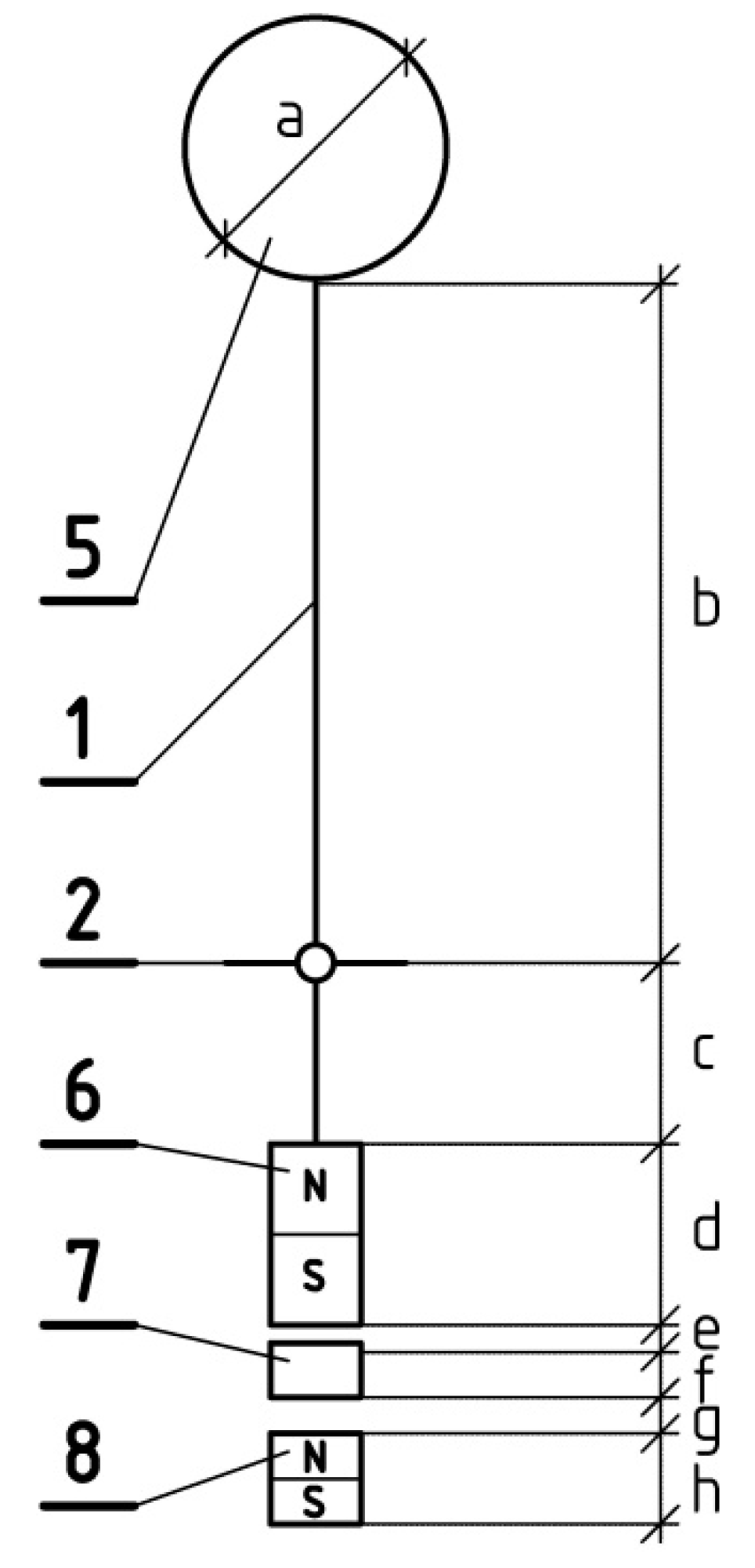
2. Energy Harvester Concept

The proposed energy harvester is designed to convert short, impulsive, turbulent airflows into electrical energy. Such flows occur in the vicinity of roads, highways, and railway tracks, among other locations, and are caused by passing vehicles. The harvester can be used to power local low-power electrical devices. Examples of such devices include control, signaling, monitoring, and data transmission systems. Figure 1 shows a schematic concept of the construction of the energy harvester.
The device is constructed in the form of a pendulum that can swing in any direction in the horizontal plane. The pendulum arm is a rod (1) mounted by a joint (2) in a cylindrical housing (3). The housing is placed stably on the ground (4). The joint (2) consists of a movable part attached to the rod (1) and a stationary part that is permanently attached to the housing. The joint (2) enables the free swinging movement of the rod, but does not allow the rod to move in the vertical direction. An aerodynamic element (5) is mounted at the upper end of the rod (1), made in the form of a ball, a cylinder, or another element interacting aerodynamically with the pulsating airflow. An upper permanent magnet (6) is mounted at the lower end of the rod (1). An induction coil (7) is placed directly under the magnet (6) and is permanently attached to the housing. The coil (7) is wound in the form of horizontal, circular turns and has the shape of a horizontal torus. During the pendular movement of the rod (1), the magnet (6) moves over the coil (7), causing an electromotive force to be generated in the coil. Under the coil (7), there is a second, lower permanent magnet (8) attached to the housing (3) and it is oriented in such a way that an attractive force occurs between magnets (6) and (8). The last important element of the energy harvester structure is the elastic bumper (9), which is attached to the housing (3), which limits the amplitude of the pendular movement of the rod (1) for strong air pulses. The operation of the described harvester consists of the fact that the airflow pulse (V) causes the rod (1) to momentarily deflect from the vertical equilibrium position, and the gravity acting on the mass of the magnet (6) and the attractive effect of the magnets (6) and (8) generate a force that brings the rod (1) to a vertical equilibrium position. It causes a momentary oscillatory pendular movement. The movement of the permanent magnet (6) attached to the lower end of the rod (1) over the induction coil (7), in accordance with the principle of electromagnetic induction, generates an electromotive force in the coil (7) and the creation of a useful electric voltage at the terminals (U). The use of the lower magnet (8) in the harvester allows for an increase in the frequency of the pendulum oscillations by increasing the force, bringing the pendulum to a vertical position and acting together with the force of gravity. It also enables the maintenance of the stability of the pendulum near the vertical position in the absence of an aerodynamic influence. During the initial design work, various configurations of magnet settings were tried. For example, in the initial phase of the project, a configuration of repulsive magnets arranged in a horizontal circle was tested, but no significant improvement was achieved. Ultimately, the configuration presented in the article was chosen for the tests, which allowed obtaining relatively large signals. In this configuration, the pendulum’s movement is accelerated during the move over the coil, which allows for inducing higher voltages. Of course, other configurations are possible, which requires further research; in particular, original and effective ideas are required.
Additionally, the rod (1) can be made of a material with elastic properties, which allows for its temporary elastic deformation, so the upper and lower parts of the rod can move and oscillate asynchronously. The presented energy harvester can be equipped with an aerodynamic element (5) made in the form of an artificial plant, for example, a reed. Placing a set of such harvesters by the road or railway tracks will create an observer-friendly effect of reeds waving in the wind, while also obtaining energy from the environment.

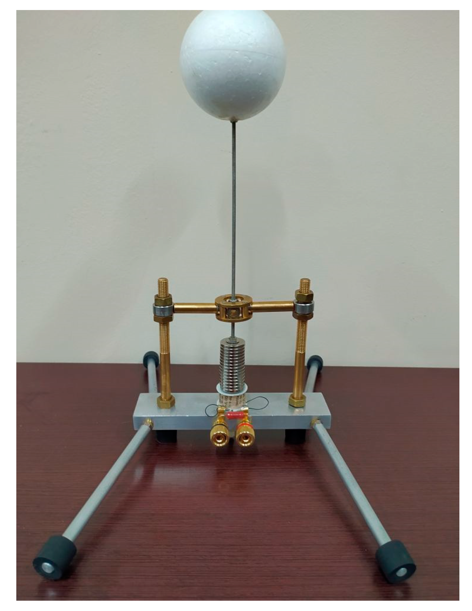
3. Construction of a Prototype Electromagnetic Energy Harvester

Based on the presented concept, a prototype, i.e., a laboratory-based, physical model of an energy harvester, was built for research purposes. This harvester is shown in Figure 2.
The pendulum arm is made in the form of a threaded rod with a diameter of 3 mm. The rod is mounted in a joint that enables pendulum movement in all directions of the horizontal plane. To minimize friction, the joint is made in the form of a set of two pairs of miniature 10 × 3 mm ball bearings with perpendicular, horizontal brass axes. The rod is attached to one of the axles, and the other axle is mounted on vertical brass side brackets. In order to enable changes in the geometric parameters of the harvester during the tests, these brackets are threaded and allow for changing the height of the joint mounting. It is also possible to change the height of the threaded rod mounting in the joint. The brackets are connected to the aluminum base of the device. Styrofoam balls are used as the aerodynamic element. Three balls with diameters of 67, 57, and 47 mm and masses of 4.96, 3.64, and 2.33 g were prepared for the tests. The balls have a glued threaded bed, enabling them to be mounted on the upper end of the rod. Neodymium ring magnets were used as permanent magnets in the harvester prototype. The outer diameter of the magnets is 19.5 mm, and the height is 2.6 mm. The magnets have a central hole with a diameter of 4 mm. The mass of a single magnet is 5 g. The magnetic induction in the geometric center of the magnetic pole surface is about 0.27 T. A set of 15 such magnets connected in the shape of a cylinder was mounted at the bottom of the pendulum rod. A ready-made coil from commercial relay was used in the presented prototype. An induction coil with an outer diameter of 20 mm and an inner diameter of 8 mm was placed under the magnets. The height of the coil is 15 mm. The coil was attached to an aluminum base. The coil contains 10 k turns of copper wire with a cross-section of about 0.003 mm2 and its resistance is 7.58 kΩ. The ends of the coil winding were connected to terminal connectors, enabling the connection of a load and voltage measurement. Under the coil, on the lower side of the base, there is a plastic screw, enabling the attachment of the lower magnets. The tests used a configuration of 3, 6, and 9 magnets placed under the coil, or no magnets. The schematic representation shown in Figure 3 shows the dimensions of the harvester used in the prototype in the series of measurements carried out, marked with symbols.
The designation of the harvester elements is in accordance with Figure 1. Note: a—diameter of the ball aerodynamic element; b—distance of the ball from the joint; c—distance of the joint from the top of the magnet (6); d—height of the magnet (6); e—gap between the magnet (6) and the coil; f—height of the coil; g—thickness of the aluminum base; h—height of the magnet (8).

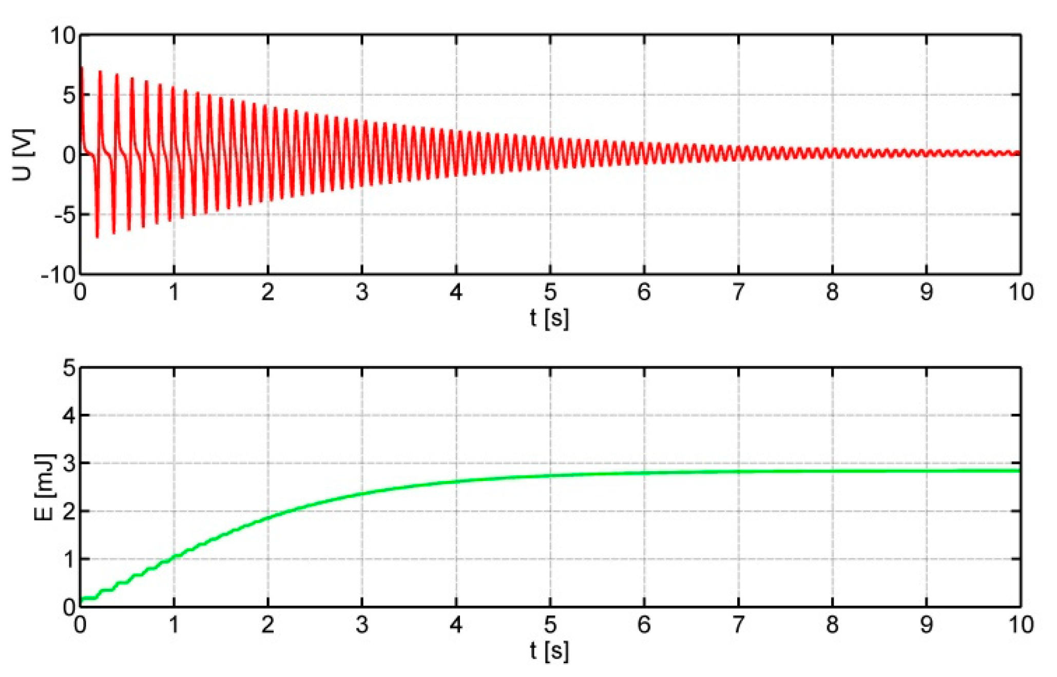
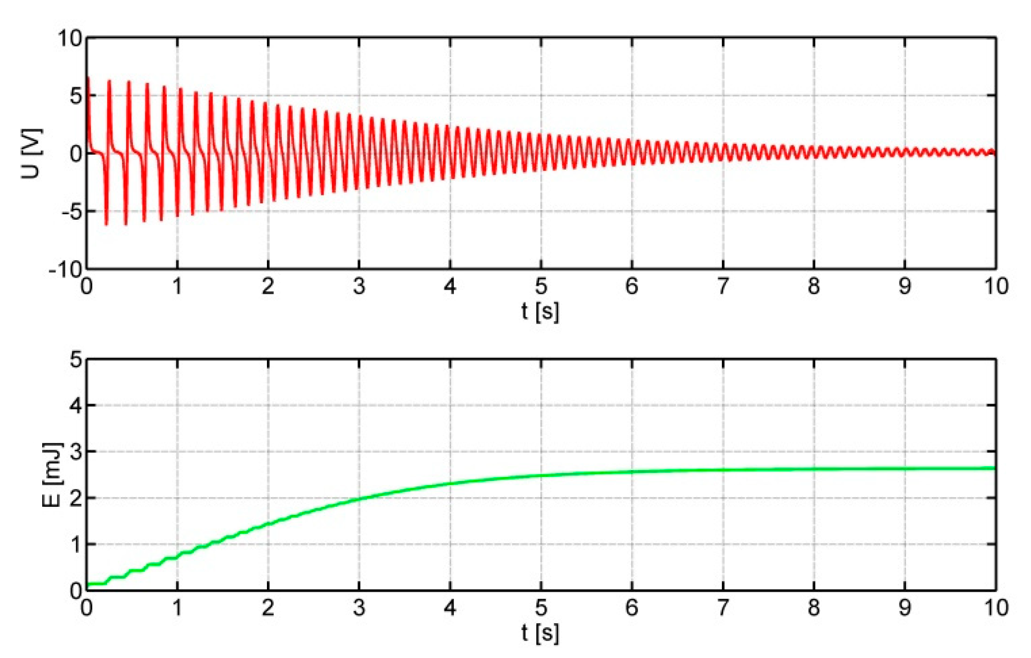
4. Experimental Tests of the Prototype

In order to assess the initial concept and parameters of the harvester, a series of experimental laboratory tests were carried out. The initial tests consisted of deflecting the harvester rod by a given angle, then releasing it and recording the voltage output signal. The tests aimed to measure the energy efficiency of the prototype under repeatable excitation conditions for different configurations. The configurations differ in the number of lower magnets and the ratio (b/c) between the lengths of the lower and upper parts of the pendulum rod. This article will present the results for configurations with constant parameters: a = 67 mm, d = 39 mm, e = 1 mm, f = 15 mm, g = 5 mm. A resistive load of the output signal from the harvester R = 10 kΩ was applied. A load resistor was connected to the coil terminals, on which the voltage was measured and recorded. During the tests, several coils with different resistances were used, for which the same load with a resistance of 10 kΩ was used for comparison purposes. Theoretically, of course, the greatest power is on a matched load with impedance coupled to the source impedance. However, in real use, the signal must be rectified in a diode rectifier, which causes voltage losses. The author used a load with a resistance that is slightly higher than the optimal resistance, which enables higher voltages to come from the converter, thus enabling one to take potential losses on the diodes into account.
The initial angle of deflection of the pendulum relative to the vertical was set at α = 40°. The values of the parameters, changed for individual configurations, are presented in Table 1.
The measurements recorded the output voltage from the harvester over a period of 10 s and determined the electrical energy generated by the harvester on a resistive load during this time. The signals were recorded using a Rohde Schwartz RM-3004 oscilloscope with a 10-bit resolution, at a sampling rate of 50 kSa/s.
In the case of presented preliminary studies, the energy obtained on the load was calculated based on the measured voltage and load resistance. The output energy was calculated by integrating over time the square of the output voltage divided by the load resistance. In a real solution, it is of course necessary to rectify the signal and collect energy in a capacitor or an accumulator. In addition, when using a matrix of many such harvesters, it is necessary to sum up the energy from individual sources. This requires the use of an appropriate diode system that cooperates with an element that stores energy.
The signal waveforms for individual configurations are shown in Figure 4, Figure 5, Figure 6, Figure 7, Figure 8, Figure 9, Figure 10 and Figure 11.
For all the presented configurations, the energy (E) obtained in 10 s at a given deflection angle of α = 40° was determined. From the Fourier analysis of voltage waveforms, the dominant frequency (f) of the harvester pendulum oscillations was determined. In dynamometric measurements, the moment of force (M) necessary to deflect the pendulum by an angle of α = 40° was measured. In the SRMI PAS Krakow wind tunnel [75,76,77], the airflow velocity (V), which causes the pendulum deflections by an angle of α = 40°, was measured. Figure 12 shows the prototype harvester in a wind tunnel. The results of the measurements are presented in Table 2.
In preliminary tests of the prototype of the pulse airflow harvester, energy in the range of 0.24 to 4.44 mJ was obtained in a single cycle, depending on the configuration. The amounts of energy are small, but they can be increased by optimizing the design and parameters of the harvester and using a set of connected devices. The use of lower magnets in the prototype significantly increases the frequency of pendulum oscillation, and thus the energy obtained. Extending the pendulum below the joint also allowed for an increase in the amount of energy obtained at the same angle of initial deflection. The airflow velocities necessary to obtain the given deflection range from 11.3 to 24.9 m/s in the conducted experiments. Of course, the use of lower magnets requires greater moments of force to obtain the deflection of the pendulum, and therefore also greater air pulse velocities. However, near a highway, motorway, or railway line, where vehicles travel at speeds exceeding 100 km/h, the passage of a single vehicle causes pulsating airflows in the desired speed range.

5. Conclusions

The article proposes an alternative concept to solutions using a turbine for an airflow energy harvester. The described harvester is designed especially for use in areas where there are strong, short-term airflow impulses of anthropogenic or natural origin. The harvester is characterized by a simple design that does not contain rotating elements, gears, or complex mechanical systems for transferring energy. Therefore, it should be characterized by high reliability and long exploitation life. A set of such harvesters equipped with aerodynamic elements in a form imitating vegetation can harmoniously fit into the landscape, causing the effect of reeds waving in the wind.
The article presents sample results obtained for the constructed prototype. The tests assumed a maximum deflection angle of 40o, and two extreme b/c ratios that are possible to obtain in the physical prototype. Of course, in such conditions, the potential energy of the deflected pendulum is not the same. The presented results should be treated as preliminary, allowing for the optimization of the prototype design. The tests in the wind tunnel were limited to determining the speed of the airflow pulse, which, in the given conditions, enabled the author to obtain the assumed maximum deflection. The results obtained during the tests will serve as a basis for the development and optimization of the harvester and may also be a starting point for other researchers developing concepts of vibrating electromagnetic harvesters.
The prototype presented in the article is certainly not an optimal design. Many readymade, easily available elements were used here. These elements dictated the dimensions of the prototype to some extent. The optimization of the harvester parameters requires further work and research. In particular, the shape and dimensions of the aerodynamic elements and the length of the vertical rod, both above and below the joint, should be optimized. The use of an element with greater aerodynamic drag and the extension of the upper part of the rod might allow the harvester to be used in the range of lower flow velocities. The extension of the lower part of the rod in the prototype tests allowed for an increase in the amount of energy obtained at a given deflection angle, but this length must be correlated with the dimensions of the magnets and coil. The magnets and coil used require selection in terms of shape, dimensions, and parameters. The methods of summing energy from non-synchronously operating devices should also be analyzed. The author of the present paper plans to continue the research and optimize this harvester. In summary, the proposed harvester is one of many possible devices for converting small amounts of energy from the environment into electrical energy to power independent low-power systems. The choice of the energy conversion method and the harvester design are always influenced by local conditions at the place of installation, required parameters, type and energy demand of the powered system, operational and economic considerations, and even ecological and aesthetic conditions.
The presented project should be treated as a study on alternative solutions to rotary transducers. Rotary transducers, in most cases, allow one to obtain more energy than vibrating transducers. Nevertheless, in cases of short, turbulent, impulsive airflows, such a transducer may show certain advantages over a rotary transducer. Rotary transducers show significant inertia and, moreover, do not allow for the use of all three spatial components of the velocity vector. In further research, it is possible to search for an optimized design of vibrating transducers, ensuring greater efficiency. Another aspect is the possibility of constructing a set of vibrating transducers that imitate a natural object, for example, waving vegetation. In the case of rotary transducers, this is rather impossible, and the aesthetic and ecological aspect may be important in some applications, e.g., in national parks.

Funding

This research was completed in 2024 as part of a statutory work carried out at the Strata Mechanics Research Institute of the Polish Academy of Sciences in Krakow, Poland.

Data Availability Statement

The original contributions presented in the study are included in the article, further inquiries can be directed to the corresponding author.

Conflicts of Interest

The author declares no conflicts of interest.

References

  1. Zheng, X.; He, L.; Wang, S.; Liu, X.; Liu, R.; Cheng, G. A review of piezoelectric energy harvesters for harvesting wind energy. Sens. Actuators A Phys. 2023, 352, 114190. [Google Scholar] [CrossRef]
  2. Sun, Y.; Li, Y.-Z.; Yuan, M. Requirements, challenges, and novel ideas for wearables on power supply and energy harvesting. Nano Energy 2023, 115, 108715. [Google Scholar] [CrossRef]
  3. Ligęza, P. On Search for Unconventional Energy Sources for Harvesting. Energies 2024, 17, 1091. [Google Scholar] [CrossRef]
  4. Saifi, S.; Xiao, X.; Cheng, S.; Guo, H.; Zhang, J.; Müller-Buschbaum, P.; Zhou, G.; Xu, X.; Cheng, H.-M. An ultraflexible energy harvesting-storage system for wearable applications. Nat. Commun. 2024, 15, 6546. [Google Scholar] [CrossRef]
  5. Liang, Z.; He, J.; Hu, C.; Pu, X.; Khani, H.; Dai, L.; Fan, D.; Manthiram, A.; Wang, Z.-L. Next-Generation Energy Harvesting and Storage Technologies for Robots Across All Scales. Adv. Intell. Syst. 2023, 5, 2200045. [Google Scholar] [CrossRef]
  6. Ligęza, P. Essential Assessment of Last-Decade Progress in Road Energy Harvesting Systems. Energy Technol. 2024, 12, 2301060. [Google Scholar] [CrossRef]
  7. Heydari, S.; Fajri, P.; Rasheduzzaman, M.; Sabzehgar, R. Maximizing regenerative braking energy recovery of electric vehicles through dynamic low-speed cutoff point detection. IEEE Trans. Transp. Electrif. 2019, 51, 262–270. [Google Scholar] [CrossRef]
  8. Wang, Z.; Huber, C.; Hu, J.; He, J.; Suess, D.; Wang, S.X. An electrodynamic energy harvester with a 3D printed magnet and optimized topology. Appl. Phys. Lett. 2019, 114, 013902. [Google Scholar] [CrossRef]
  9. Iqbal, M.; Khan, F.U. Hybrid vibration and wind energy harvesting using combined piezoelectric and electromagnetic conversion for bridge health monitoring applications. Energy Convers. Manag. 2018, 172, 611–618. [Google Scholar] [CrossRef]
  10. Nabavi, S.F.; Farshidianfar, A.; Afsharfard, A. Novel piezoelectric-based ocean wave energy harvesting from offshore buoys. Appl. Ocean Res. 2018, 76, 174–183. [Google Scholar] [CrossRef]
  11. Covaci, C.; Gontean, A. Piezoelectric energy harvesting solutions: A review. Sensors 2020, 2012, 3512. [Google Scholar] [CrossRef] [PubMed]
  12. Jie, Y.; Jia, X.; Zou, J.; Chen, Y.; Wang, N.; Wang, Z.L.; Cao, X. Natural Leaf Made Triboelectric Nanogenerator for Harvesting Environmental Mechanical Energy. Adv. Energy Mater. 2018, 8, 1703133. [Google Scholar] [CrossRef]
  13. Thainiramit, P.; Yingyong, P.; Isarakorn, D. Impact-driven energy harvesting: Piezoelectric versus triboelectric energy harvesters. Sensors 2020, 2020, 5828. [Google Scholar] [CrossRef] [PubMed]
  14. Xu, Y.; Yang, W.; Lu, X.; Yang, Y.; Li, J.; Wen, J.; Cheng, T.; Wang, Z.L. Triboelectric Nanogenerator for Ocean Wave Graded Energy Harvesting and Condition Monitoring. ACS Nano 2021, 15, 16368–16375. [Google Scholar] [CrossRef]
  15. Liang, X.; Liu, Z.; Feng, Y.; Han, J.; Li, L.; An, J.; Chen, P.; Jiang, T.; Wang, Z.L. Spherical triboelectric nanogenerator based on spring-assisted swing structure for effective water wave energy harvesting. Nano Energy 2021, 83, 105836. [Google Scholar] [CrossRef]
  16. Catalan, L.; Garacochea, A.; Casi, A.; Araiz, M.; Aranguren, P.; Astrain, D. Experimental Evidence of the Viability of Thermoelectric Generators to Power Volcanic Monitoring Stations. Sensors 2020, 20, 4839. [Google Scholar] [CrossRef]
  17. Ramya, G.; Sivakumar, R.; Prabhakar, G.; Maheswari, K.U.; Karthi, K. Architecture of Low Power Energy Harvester Using Hybrid Input Solar, Peltier Thermo Electric and Vibrational Generation. Int. Res. J. Innov. Eng. Technol. 2021, 54, 68. [Google Scholar]
  18. Koketsu, K.; Tanzawa, T. A Design of a Thermoelectric Energy Harvester for Minimizing Sensor Module Cost. Electronics 2022, 1121, 3441. [Google Scholar] [CrossRef]
  19. Sultana, A.; Alam, M.M.; Middya, T.R.; Mandal, D. A pyroelectric generator as a self-powered temperature sensor for sustainable thermal energy harvesting from waste heat and human body heat. Appl. Energy 2018, 221, 299–307. [Google Scholar] [CrossRef]
  20. Thakre, A.; Kumar, A.; Song, H.C.; Jeong, D.Y.; Ryu, J. Pyroelectric energy conversion and its applications—Flexible energy harvesters and sensors. Sensors 2019, 199, 2170. [Google Scholar] [CrossRef]
  21. Mondal, R.; Al Mahadi Hasan, M.; Baik, J.M.; Yang, Y. Advanced pyroelectric materials for energy harvesting and sensing applications. Mater. Today 2023, 66, 273–301. [Google Scholar] [CrossRef]
  22. Pei, J.; Zhou, B.; Lyu, L. e-Road: The largest energy supply of the future? Appl. Energy 2019, 241, 174–183. [Google Scholar] [CrossRef]
  23. Lopez-Gasso, A.; Beriain, A.; Solar, H.; Berenguer, R. Power Management Unit for Solar Energy Harvester Assisted Batteryless Wireless Sensor Node. Sensors 2022, 22, 7908. [Google Scholar] [CrossRef] [PubMed]
  24. Zhang, K.; Chen, M.; Yang, Y.; Zhong, T.; Zhu, R.; Zhang, F.; Qian, Z.; Lü, G.; Yan, J. Quantifying the photovoltaic potential of highways in China. Appl. Energy 2022, 324, 119600. [Google Scholar] [CrossRef]
  25. Lee, J.; Kim, D.; Lee, S.; Lim, J. Fundamental Study of Energy Harvesting Using Thermoelectric Effect on Concrete Structure in Road. Adv. Mater. Res. 2014, 1044–1045, 332–337. [Google Scholar] [CrossRef]
  26. Xie, Z.; Shi, K.; Song, L.; Hou, X. Experimental and field study of a pavement thermoelectric energy harvesting system based on the seebeck effect. J. Electron. Mater. 2023, 52, 209–218. [Google Scholar] [CrossRef]
  27. Cansiz, M.; Altinel, D.; Kurt, G.K. Efficiency in RF energy harvesting systems: A comprehensive review. Energy 2019, 174, 292–309. [Google Scholar] [CrossRef]
  28. Shoji, E. New Insights into Radio Wave Energy Harvesting across Wide Geographical Ranges Harnessing Medium-Wave Radio Broadcasting Infrastructure. Energy Technol. 2024, 121, 2300604. [Google Scholar] [CrossRef]
  29. Mukherjee, S.; Bhowmick, S.; Mukherjee, R. Harvesting Energy from Thunderstorm, A New Source of Renewable Energy—Review. Int. J. Adv. Sci. Eng. 2019, 6 (Suppl. S1), 64–67. [Google Scholar]
  30. Zhang, R.; Wang, M.; Wan, Z.; Wu, Z.; Xiao, X. Laser direct writing based flexible solar energy harvester. Results Eng. 2023, 19, 101314. [Google Scholar] [CrossRef]
  31. Alamayreh, M.I.; Alahmer, A. Design a solar harvester system capturing light and thermal energy coupled with a novel direct thermal energy storage and nanoparticles. Int. J. Thermofluids 2023, 18, 100328. [Google Scholar] [CrossRef]
  32. Lingaraja, D.; Kumar, S.P.; Aravind, T.; Srinivasan, T.K.; Ram, G.D.; Ramya, S. Design of Solar Energy Harvester for Smart Home Application. In Proceedings of the 2023 5th International Conference on Smart Systems and Inventive Technology ICSSIT, Tirunelveli, India, 23–25 January 2023; IEEE: Piscataway, NJ, USA, 2023; pp. 1–5. [Google Scholar]
  33. Faria, C.L.; Martins, M.S.; Matos, T.; Lima, R.; Miranda, J.M.; Gonçalves, L.M. Underwater Energy Harvesting to Extend Operation Time of Submersible Sensors. Sensors 2022, 22, 1341. [Google Scholar] [CrossRef] [PubMed]
  34. Sui, G.; Shan, X.; Hou, C.; Tian, H.; Hu, J.; Xie, T. An underwater piezoelectric energy harvester based on magnetic coupling adaptable to low-speed water flow. Mech. Syst. Signal Process. 2023, 184, 109729. [Google Scholar] [CrossRef]
  35. Wang, S.; He, L.; Wang, H.; Li, X.; Sun, B.; Lin, J. Energy harvesting from water impact using piezoelectric energy harvester. Rev. Sci. Instrum. 2024, 95, 2. [Google Scholar] [CrossRef] [PubMed]
  36. Xie, Q.; Zhang, T.; Pan, Y.; Zhang, Z.; Yuan, Y.; Liu, Y. A novel oscillating buoy wave energy harvester based on a spatial double X-shaped mechanism for self-powered sensors in sea-crossing bridges. Energy Convers. Manag. 2020, 204, 112286. [Google Scholar] [CrossRef]
  37. Wu, W.; Pan, Z.; Zhou, J.; Wang, Y.; Ma, J.; Li, J.; Hu, Y.; Wen, J.; Wang, X. Wind-Speed-Adaptive Resonant Piezoelectric Energy Harvester for Offshore Wind Energy Collection. Sensors 2024, 24, 1371. [Google Scholar] [CrossRef] [PubMed]
  38. Viola, F. Comparison Among Different Rainfall Energy Harvesting Structures. Appl. Sci. 2018, 8, 955. [Google Scholar] [CrossRef]
  39. Bao, B.; Wang, Q. A rain energy harvester using a self-release tank. Mech. Syst. Signal Process. 2021, 147, 107099. [Google Scholar] [CrossRef]
  40. Cheng, B.; Niu, S.; Xu, Q.; Wen, J.; Bai, S.; Qin, Y. Gridding, Triboelectric Nanogenerator for Raindrop Energy Harvesting. ACS Appl. Mater. Interfaces 2021, 13, 59975–59982. [Google Scholar] [CrossRef]
  41. Ahmed, A.; Hassan, I.; Mosa, I.M.; Elsanadidy, E.; Phadke, G.S.; El-Kady, M.F.; Rusling, J.F.; Selvaganapathy, P.R.; Kaner, R.B. All printable snow-based triboelectric nanogenerator. Nano Energy 2019, 60, 17–25. [Google Scholar] [CrossRef]
  42. Peters, N.L.; Oppenheimer, C.; Jones, B.; Rose, M.; Kyle, P. Harnessing Erebus volcano’s thermal energy to power year-round monitoring. Antarct. Sci. 2021, 331, 73–80. [Google Scholar] [CrossRef]
  43. Zhang, H.; Wu, X.; Pan, Y.; Azam, A.; Zhang, Z. A novel vibration energy harvester based on eccentric semicircular rotor for self-powered applications in wildlife monitoring. Energy Convers. Manag. 2021, 247, 114674. [Google Scholar] [CrossRef]
  44. Wang, X.; Shi, Y.; Yang, P.; Tao, X.; Li, S.; Lei, R.; Liu, Z.; Wang, Z.L.; Chen, X. Fish-Wearable Data Snooping Platform for Underwater Energy Harvesting and Fish Behavior Monitoring. Small 2022, 18, 2107232. [Google Scholar] [CrossRef] [PubMed]
  45. Yan, C.; Gao, Y.; Zhao, S.; Zhang, S.; Zhou, Y.; Deng, W.; Li, Z.; Jiang, G.; Jin, L.; Tian, G.; et al. A linear-to-rotary hybrid nanogenerator for high-performance wearable biomechanical energy harvesting. Nano Energy 2020, 67, 104235. [Google Scholar] [CrossRef]
  46. Lund, A.; Tian, Y.; Darabi, S.; Müller, C. A polymer-based textile thermoelectric generator for wearable energy harvesting. J. Power Sources 2020, 480, 228836. [Google Scholar] [CrossRef]
  47. Roshani, H.; Dessouky, S.; Arturo Montoya, A.T. Papagiannakis, Energy harvesting from asphalt pavement roadways vehicle-induced stresses: A feasibility study. Appl. Energy 2016, 182, 210–218. [Google Scholar] [CrossRef]
  48. Papagiannakis, A.T.; Dessouky, S.; Montoya, A.; Roshani, H. Energy Harvesting from Roadways. Procedia Comput. Sci. 2016, 83, 758–765. [Google Scholar] [CrossRef]
  49. Qi, L.; Pan, H.; Bano, S.; Zhu, M.; Liu, J.; Zhang, Z.; Liu, Y.; Yuan, Y. A high-efficiency road energy harvester based on a chessboard sliding plate using semi-metal friction materials for self-powered applications in road traffic. Energy Convers. Manag. 2018, 165, 748–760. [Google Scholar] [CrossRef]
  50. Gholikhani, M.; Nasouri, R.; Tahami, S.A.; Legette, S.; Dessouky, S.; Montoya, A. Harvesting kinetic energy from roadway pavement through an electromagnetic speed bump. Appl. Energy 2019, 250, 503–511. [Google Scholar] [CrossRef]
  51. Sun, M.; Wang, W.; Zheng, P.; Luo, D.; Zhang, Z. A novel road energy harvesting system based on a spatial double V-shaped mechanism for near-zero-energy toll stations on expressways. Sens. Actuators A Phys. 2021, 323, 112648. [Google Scholar] [CrossRef]
  52. Kim, C.I.; Kim, K.-B.; Jeon, J.-H.; Jeong, Y.H.; Cho, J.H.; Paik, J.H.; Gang, I.-S.; Lee, M.-Y.; Nahm, S.; Lee, Y.-J.; et al. Development and Evaluation of the Road Energy Harvester Using Piezoelectric Cantilevers. J. Korean Inst. Electr. Electron. Mater. Eng. 2012, 25, 511–515. [Google Scholar] [CrossRef]
  53. Xiong, H.; Wang, L. Piezoelectric energy harvester for public roadway: On-site installation and evaluation. Appl. Energy 2016, 174, 101–107. [Google Scholar] [CrossRef]
  54. Chen, N.; Jung, H.J.; Jabbar, H.; Sung, T.H.; Wei, T. A piezoelectric impact-induced vibration cantilever energy harvester from speed bump with a low-power power management circuit. Sens. Actuators A Phys. 2017, 254, 134–144. [Google Scholar] [CrossRef]
  55. Yang, C.H.; Song, Y.; Woo, M.S.; Eom, J.H.; Song, G.J.; Kim, J.H.; Kim, J.; Lee, T.H.; Choi, J.Y.; Sung, T.H. Feasibility study of impact-based piezoelectric road energy harvester for wireless sensor networks in smart highways. Sens. Actuators A Phys. 2017, 261, 317–324. [Google Scholar] [CrossRef]
  56. Mazlan, M.; Abd Manan, M.H.; Yusof, N.F.M. Modelling and Analysis Road Energy Harvester Using Piezoelectric Tranducer. Int. J. Eng. Technol. 2019, 8, 94–100. [Google Scholar]
  57. Gareh, S.; Kok, B.C.; Yee, M.H.; Borhana, A.A.; Alswed, S.K. Optimization of the Compression-Based Piezoelectric Traffic Model CPTM, for Road Energy Harvesting Application. Int. J. Renew. Energy Res.-IJRER 2019, 9, 1272–1282. [Google Scholar]
  58. Sherren, A.; Fink, K.; Eshelman, J.; Taha, L.Y.; Anwar, S.; Brennecke, C. Design and Modelling of Piezoelectric Road Energy Harvesting. Open J. Energy Effic. 2022, 11, 24–36. [Google Scholar] [CrossRef]
  59. Cahill, P.; Hazra, B.; Karoumi, R.; Mathewson, A.; Pakrashi, V. Vibration energy harvesting based monitoring of an operational bridge undergoing forced vibration and train passage. Mech. Syst. Signal Process. 2018, 106, 265–283. [Google Scholar] [CrossRef]
  60. Sheng, W.; Xiang, H.; Zhang, Z.; Yuan, X. High-efficiency piezoelectric energy harvester for vehicle-induced bridge vibrations: Theory and experiment. Compos. Struct. 2022, 299, 116040. [Google Scholar] [CrossRef]
  61. Muscat, A.; Bhattacharya, S.; Zhu, Y. Electromagnetic vibrational energy harvesters: A review. Sensors 2022, 22, 5555. [Google Scholar] [CrossRef]
  62. Pan, Y.; Lin, T.; Qian, F.; Liu, C.; Yu, J.; Zuo, J.; Zuo, L. Modeling and field-test of a compact electromagnetic energy harvester for railroad transportation. Appl. Energy 2019, 247, 309–321. [Google Scholar] [CrossRef]
  63. Zuo, J.; Dong, L.; Yang, F.; Guo, Z.; Wang, T.; Zuo, L. Energy harvesting solutions for railway transportation: A comprehensive review. Renew. Energy 2023, 202, 56–87. [Google Scholar] [CrossRef]
  64. Wang, H.; Yi, M.; Zeng, X.; Zhang, T.; Luo, D.; Zhang, Z. A hybrid, self-adapting drag-lift conversion wind energy harvesting system for railway turnout monitoring on the Tibetan Plateau. Sustain. Energy Technol. Assess. 2021, 46, 101262. [Google Scholar] [CrossRef]
  65. Pan, H.; Li, H.; Zhang, T.; Laghari, A.A.; Zhang, Z.; Yuan, Y.; Qian, B. A portable renewable wind energy harvesting system integrated S-rotor and H-rotor for self-powered applications in high-speed railway tunnels. Energy Convers. Manag. 2019, 196, 56–68. [Google Scholar] [CrossRef]
  66. Ligęza, P. Modification of Hot-Wire Anemometers Frequency Bandwidth Measurement Method. Sensors 2020, 20, 1595. [Google Scholar] [CrossRef]
  67. Ligęza, P. Basic, Advanced, and Sophisticated Approaches to the Current and Forecast Challenges of Wind Energy. Energies 2021, 14, 8147. [Google Scholar] [CrossRef]
  68. Ligęza, P. Dynamic Error Correction Method in Tachometric Anemometers for Measurements of Wind Energy. Energies 2022, 15, 4132. [Google Scholar] [CrossRef]
  69. Ligęza, P.; Jamróz, P. A Hot-Wire Anemometer with Automatically Adjusted Dynamic Properties for Wind Energy Spectrum Analysis. Energies 2022, 15, 4618. [Google Scholar] [CrossRef]
  70. Tian, W.; Mao, Z.; Li, Y. Numerical Simulations of a VAWT in the Wake of a Moving Car. Energies 2017, 10, 478. [Google Scholar] [CrossRef]
  71. Liu, C.; Chen, L.; Lee, H.P.; Yang, Y.; Zhang, X. A review of the inerter and inerter-based vibration isolation: Theory, devices, and applications. J. Frankl. Inst. 2022, 359, 7677–7707. [Google Scholar] [CrossRef]
  72. Ambrożkiewicz, B.; Litak, G.; Wolszczak, P. Modelling of Electromagnetic Energy Harvester with Rotational Pendulum Using Mechanical Vibrations to Scavenge Electrical Energy. Appl. Sci. 2020, 10, 671. [Google Scholar] [CrossRef]
  73. Hasani, M.; Rahaghi, M.I. The optimization of an electromagnetic vibration energy harvester based on developed electromagnetic damping models. Energy Convers. Manag. 2022, 254, 115271. [Google Scholar] [CrossRef]
  74. Monaco, M.L.; Russo, C.; Somà, A. Numerical and experimental performance study of two-degrees-of-freedom electromagnetic energy harvesters. Energy Convers. Manag. X 2023, 18, 100348. [Google Scholar] [CrossRef]
  75. Ligęza, P. Reconstructing the trajectory of the object’s motion on the basis of measuring the components of its velocity. Measurement 2023, 221, 113546. [Google Scholar] [CrossRef]
  76. Ostrogórski, P.; Skotniczny, P. Methane Emission Measurements Along Underground Galleries of Coal Mine. Arch. Min. Sci. 2024, 69, 107–114. [Google Scholar] [CrossRef]
  77. Jamróz, P. Interaction between the Standard and the Measurement Instrument during the Flow Velocity Sensor Calibration Process. Processes 2021, 9, 1792. [Google Scholar] [CrossRef]
Figure 1. The concept of an electromagnetic energy harvester.
Energies 17 04834 g001
Figure 2. Prototype electromagnetic energy harvester.
Energies 17 04834 g002
Figure 3. Designation of dimensions of the electromagnetic harvester.
Energies 17 04834 g003
Figure 4. Voltage and energy waveform from the prototype for configuration A1: without lower magnets, b/c = 8.75.
Energies 17 04834 g004
Figure 5. Voltage and energy waveform from the prototype for configuration A2: 3 lower magnets, b/c = 8.75.
Energies 17 04834 g005
Figure 6. Voltage and energy waveform from the prototype for configuration A3: 6 lower magnets, b/c = 8.75.
Energies 17 04834 g006
Figure 7. Voltage and energy waveform from the prototype for the A4 configuration: 9 lower magnets, b/c = 8.75.
Energies 17 04834 g007
Figure 8. Voltage and energy waveform from the prototype for configuration B1: without lower magnets, b/c = 5.
Energies 17 04834 g008
Figure 9. Voltage and energy waveform from the prototype for configuration B2: 3 lower magnets, b/c = 5.
Energies 17 04834 g009
Figure 10. Voltage and energy waveform from the prototype for configuration B3: 6 lower magnets, b/c = 5.
Energies 17 04834 g010
Figure 11. Voltage and energy waveform from the prototype for the B4 configuration: 9 lower magnets, b/c = 5.
Energies 17 04834 g011
Figure 12. Prototype harvester in a wind tunnel.
Energies 17 04834 g012
Table 1. Parameters changed for individual configurations.
Designation of Measurement ConfigurationNumber of Bottom Magnetsh [mm]b [mm]c [mm]b/c
A100140168.75
A237.8140168.75
A3615.6140168.75
A4923.4140168.75
B100130265
B237.8130265
B3615.6130265
B4923.4130265
Table 2. Summary of measurement results of the prototype harvester parameters for individual configurations.
Designation of Measurement ConfigurationE
[mJ]
f
[Hz]
M
[m Nm]
V
[m/s]
A10.242.3317.711.3
A21.847.8347.2 18.5
A32.859.7569.822.5
A43.3110.6778.423.9
B10.642.7418.311.9
B22.648.7747.719.2
B33.8410.7470.623.3
B44.4411.7279.424.9
Disclaimer/Publisher’s Note: The statements, opinions and data contained in all publications are solely those of the individual author(s) and contributor(s) and not of MDPI and/or the editor(s). MDPI and/or the editor(s) disclaim responsibility for any injury to people or property resulting from any ideas, methods, instructions or products referred to in the content.

