
Advancements on Lumped Modelling of Membrane Water Content for Real-Time Prognostics and Control of PEMFC


Abstract
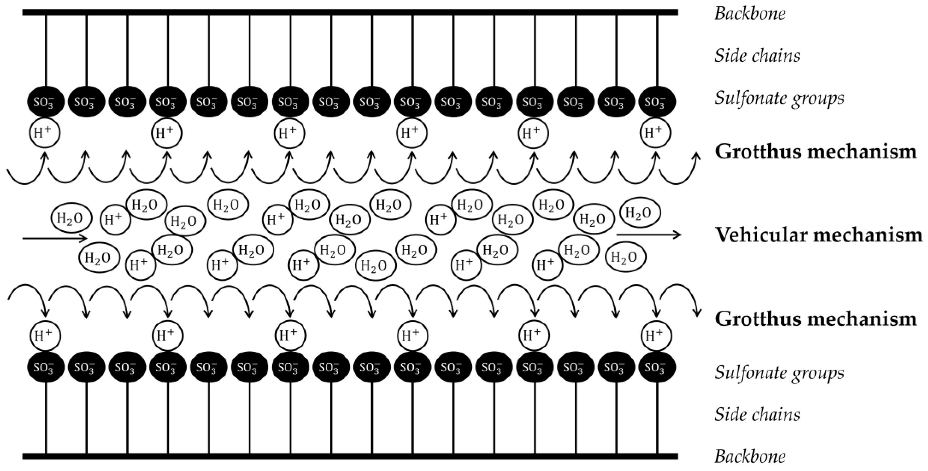
:1. Introduction
2. Analytical Solution of Membrane Dynamics Related to Water Transport
2.1. Water Mass Balance Problem Formulation
2.2. Further Simplifying Hypotheses
2.3. Nondimensionalization
2.4. Analytical Solution of the Problem
3. Application of the Integral Method
3.1. Integral Solution Definition and Calculation
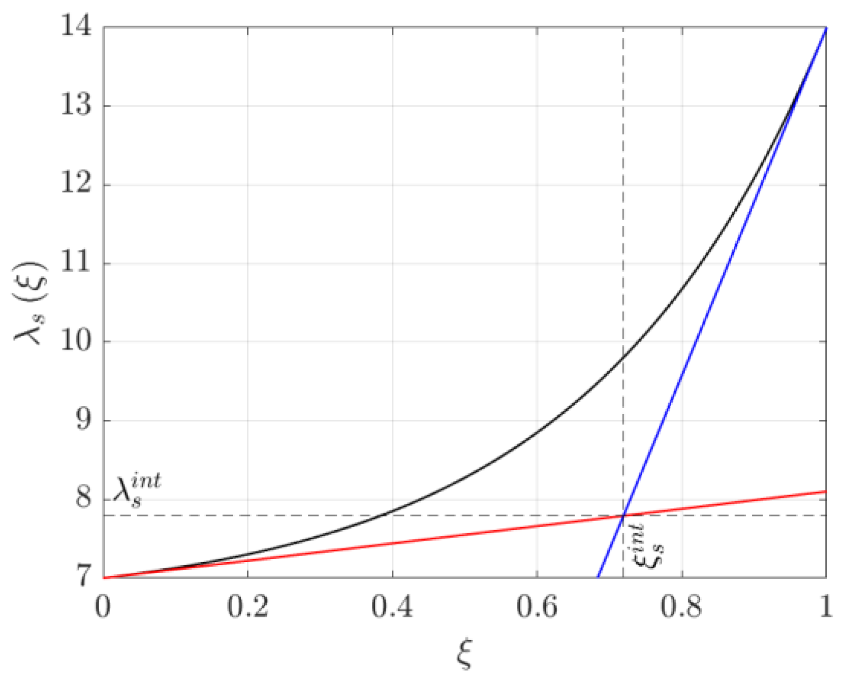
3.2. Time Constant Analysis
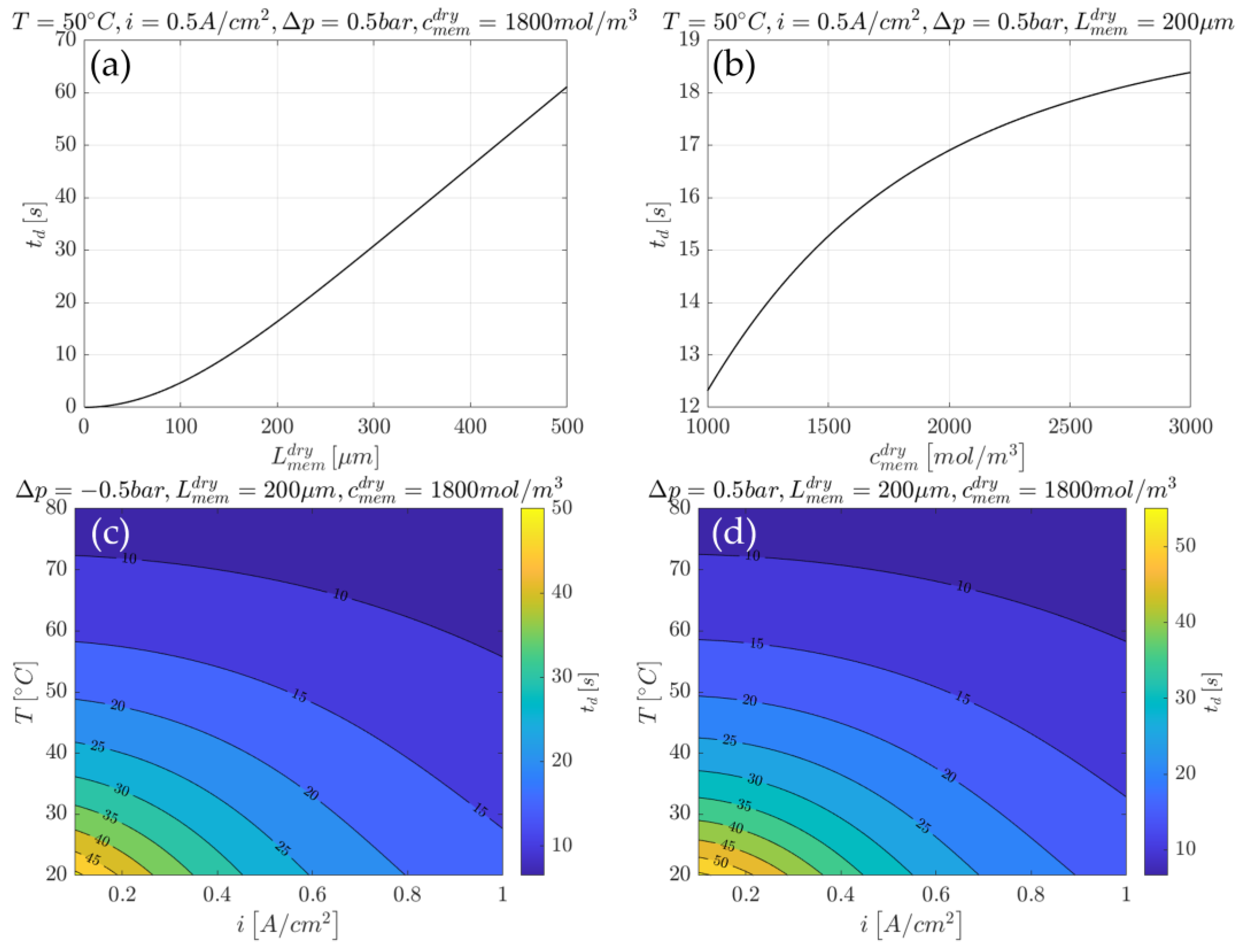
3.2.1. Example of Time Constant Use for Cell Design
3.2.2. Example of Time Constant Use for Cell Control
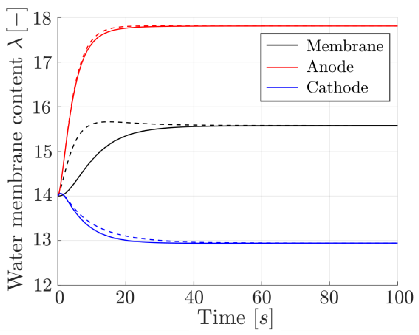
3.3. ODE Formulation for On-Board Implementation
3.4. Net Water Molar Flux Estimation
3.5. On-Board Implementation Procedure
- Compute the Pe number through Equation (25);
- compute the average steady-state solution through Equation (51);
- compute the characteristic time td through Equation (48);
- integrate the ODE of Equation (50) to obtain the solution ;
- compute the average net water molar flux for the anode and cathode through Equations (62) and (63), respectively.
4. Conclusions
Author Contributions
Funding
Data Availability Statement
Conflicts of Interest
Nomenclature
| Acronyms | |
| CL | Catalyst Layer |
| GDL | Gas Diffusion Layer |
| GFC | Gas Flow Channel |
| PDE | Partial Differential Equation |
| PEM | Proton Exchange Membrane |
| PEMF | Proton Exchange Membrane Fuel Cell |
| PTFE | Polytetrafluoroethylene |
| ODE | Ordinary Differential Equation |
| ORR | Oxygen Reduction Reaction |
| Roman Letters | |
| a | normalized membrane water content [-] |
| c | molar concentration [mol⋅m−3] |
| cn | eigenvalue [-] |
| D | diffusion coefficient [m2⋅s−1] |
| err | error function [-] |
| F | faraday’s constant [C⋅mol−1] |
| f | time function [-] |
| i | current density [A⋅m−2] |
| J | molar flux [mol⋅m−2⋅s−1] |
| k | permeability [m2] |
| kn | unsteady solution mode coefficient [-] |
| L | thickness [m] |
| n | mode number [-] |
| Pe | Peclet number [-] |
| p | pressure [Pa] |
| s | swelling factor [-] |
| T | temperature [K] |
| Tn | temporal eigenfunction [-] |
| t | time coordinate [s] |
| u | velocity [m⋅s−1] |
| Xn | spatial eigenfunction [-] |
| x | spatial coordinate [m] |
| Greek Letters | |
| Δ | Difference [-] |
| δ | Thickness fractional change [-] |
| Γ | nondimensional water membrane content function [-] |
| λ | Water content [-] |
| μw | Water viscosity [Pa⋅s] |
| τ | nondimensional time [-] |
| ξ | nondimensional spatial coordinate [-] |
| Subscripts | |
| 0 | initial condition |
| a | anode |
| c | cathode |
| conv | convection |
| d | delay |
| diff | diffusion |
| EOD | electro-osmotic drag |
| mem | membrane |
| n | mode |
| s | steady state |
| T | temperature |
| u | unsteady |
| w | water |
| % | percentage |
| Superscripts | |
| * | integral or approximated |
| chem | chemical related |
| dry | dry reference condition |
| int | intersection |
References
- Wee, J.-H. Applications of proton exchange membrane fuel cell systems. Renew. Sustain. Energy Rev. 2007, 11, 1720–1738. [Google Scholar] [CrossRef]
- Larminie, J.; Dicks, A.; McDonald, M.S. Fuel Cells Systems Explained; J. Wiley: Chichester, UK, 2003; ISBN 0-470-84857-X. [Google Scholar]
- Peighambardoust, S.; Rowshanzamir, S.; Amjadi, M. Review of the proton exchange membranes for fuel cell applications. Int. J. Hydrog. Energy 2009, 35, 9349–9384. [Google Scholar] [CrossRef]
- Valenzuela, E.; Gamboa, S.; Sebastian, P.; Moreira, J.; Pantoja, J.; Ibañez, G.; Reyes, A.; Campillo, B.; Serna, S. Proton Charge Transport in Nafion Nanochannels. J. Nano Res. 2009, 5, 31–36. [Google Scholar] [CrossRef]
- Pan, M.; Pan, C.; Li, C.; Zhao, J. A review of membranes in proton exchange membrane fuel cells: Transport phenomena, performance and durability. Renew. Sustain. Energy Rev. 2021, 141, 110771. [Google Scholar] [CrossRef]
- Jiao, K.; Li, X. Water transport in polymer electrolyte membrane fuel cells. Prog. Energy Combust. Sci. 2011, 37, 221–291. [Google Scholar] [CrossRef]
- Ji, M.; Wei, Z. A Review of Water Management in Polymer Electrolyte Membrane Fuel Cells. Energies 2009, 2, 1057–1106. [Google Scholar] [CrossRef]
- Canut, J.-M.L.; Abouatallah, R.M.; Harrington, D.A. Detection of Membrane Drying, Fuel Cell Flooding, and Anode Catalyst Poisoning on PEMFC Stacks by Electrochemical Impedance Spectroscopy. J. Electrochem. Soc. 2006, 153, A857. [Google Scholar] [CrossRef]
- Ijaodola, O.S.; Hassan, Z.E.; Ogungbemi, E.; Khatib, F.; Wilberforce, T.; Thompson, J.; Olabi, A. Energy efficiency improvements by investigating the water flooding management on proton exchange membrane fuel cell (PEMFC). Energy 2019, 179, 246–267. [Google Scholar] [CrossRef]
- Li, H.; Tang, Y.; Wang, Z.; Shi, Z.; Wu, S.; Song, D.; Zhang, J.; Fatih, K.; Zhang, J.; Wang, H.; et al. A review of water flooding issues in the proton exchange membrane fuel cell. J. Power Sources 2008, 178, 103–117. [Google Scholar] [CrossRef]
- Lim, B.H.; Majlan, E.H.; Daud, W.R.W.; Husaini, T.; Rosli, M.I. Effects of flow field design on water management and reactant distribution in PEMFC: A review. Ionics 2016, 22, 301–316. [Google Scholar] [CrossRef]
- Okonkwo, P.C.; Otor, C. A review of gas diffusion layer properties and water management in proton exchange membrane fuel cell system. Int. J. Energy Res. 2021, 45, 3780–3800. [Google Scholar] [CrossRef]
- Pourrahmani, H.; van Herle, J. Water management of the proton exchange membrane fuel cells: Optimizing the effect of microstructural properties on the gas diffusion layer liquid removal. Energy 2022, 256, 124712. [Google Scholar] [CrossRef]
- Lee, D.; Bae, J. Visualization of flooding in a single cell and stacks by using a newly-designed transparent PEMFC. Int. J. Hydrog. Energy 2021, 37, 422–435. [Google Scholar] [CrossRef]
- Kim, M.; Jung, N.; Eom, K.; Yoo, S.J.; Kim, J.Y.; Jang, J.H.; Kim, H.-J.; Hong, B.K.; Cho, E. Effects of anode flooding on the performance degradation of polymer electrolyte membrane fuel cells. J. Power Sources 2014, 266, 332–340. [Google Scholar] [CrossRef]
- Esposito, A.; Pianese, C.; Guezennec, Y.G. Coupled modeling of water transport and air–droplet interaction in the electrode of a proton exchange membrane fuel cell. J. Power Sources 2010, 195, 4149–4159. [Google Scholar] [CrossRef]
- Polverino, P.; Esposito, A.; Pianese, C. Experimental validation of a lumped model of single droplet deformation, oscillation and detachment on the GDL surface of a PEM fuel cell. J. Power Sources 2013, 38, 8934–8953. [Google Scholar] [CrossRef]
- Parrondo, J.; Ortueta, M.; Mijangos, F. Swelling behavior of PEMFC during conditioning. Braz. J. Chem. Eng. 2007, 24, 411–419. [Google Scholar] [CrossRef]
- Tiss, F.; Chouikh, R.; Guizani, A. A numerical investigation of the effects of membrane swelling in polymer electrolyte fuel cells. Energy Convers. Manag. 2013, 67, 318–324. [Google Scholar] [CrossRef]
- Hwang, R.Y.; Moon, Y.; Kim, H.M.; Kim, E.; Park, S.; Han, O.H. Measuring the water content of polymer electrolyte membranes using double points of proton magic angle spinning nuclear magnetic resonance data. Polymer 2024, 309, 127431. [Google Scholar] [CrossRef]
- Wu, Y.; Xu, L.; Zhou, S.; Yang, J.; Kockelmann, W.; Han, Y.; Li, Q.; Chen, W.; Coppens, M.O.; Shearing, P.R.; et al. Water management and mass transport of a fractal metal foam flow-field based polymer electrolyte fuel cell using operando neutron imaging. Appl. Energy 2024, 364, 123204. [Google Scholar] [CrossRef]
- Springer, T.E.; Zawodzinski, T.A.; Gottesfeld, S. Polymer Electrolyte Fuel Cell Model. J. Electrochem. Soc. 1991, 138, 2334. [Google Scholar] [CrossRef]
- Dickinson, E.J.F.; Smith, G. Modelling the Proton-Conductive Membrane in Practical Polymer Electrolyte Membrane Fuel Cell (PEMFC) Simulation: A Review. Membranes 2020, 10, 310. [Google Scholar] [CrossRef] [PubMed]
- Mazumder, S. A Generalized Phenomenological Model and Database for the Transport of Water and Current in Polymer Electrolyte Membranes. J. Electrochem. Soc. 2005, 152, A1633–A1644. [Google Scholar] [CrossRef]
- Ferrara, A.; Polverino, P.; Pianese, C. Analytical calculation of electrolyte water content of a Proton Exchange Membrane Fuel Cell for on-board modelling applications. J. Power Sources 2018, 390, 197–207. [Google Scholar] [CrossRef]
- Wang, Y.; Si, C.; Zhang, X.; Wang, X.; He, W. Electro-osmotic drag coefficient of Nafion membrane with low water Content for Proton exchange membrane fuel cells. Energy Rep. 2022, 8, 598–612. [Google Scholar] [CrossRef]
- Wang, G.; Liu, Z.; Liu, C. Molecular Study of Nonequilibrium Transport Mechanism for Proton and Water in Porous Proton Exchange Membranes. Int. J. Energy Res. 2023, 3, 1138198. [Google Scholar] [CrossRef]
- Chen, F.; Zhang, L.; Jiao, J. Modelling of Humidity Dynamics for Open-Cathode Proton Exchange Membrane Fuel Cell. World Electr. Veh. J. 2021, 12, 106. [Google Scholar] [CrossRef]
- Real, A.J.D.; Arce, A.; Bordons, C. Development and experimental validation of a PEM fuel cell dynamic model. J. Power Sources 2007, 173, 310–324. [Google Scholar] [CrossRef]
- Pathapati, P.; Xue, X.; Tang, J. A new dynamic model for predicting transient phenomena in a PEM fuel cell system. Renew. Energy 2005, 30, 1–22. [Google Scholar] [CrossRef]
- Lechartier, E.; Gouriveau, R.; Pera, M.-C.; Hissel, D.; Zerhouni, N. Static and Dynamic Modeling of a PEMFC for Prognostics Purpose. In Proceedings of the Vehicle Power and Propulsion Conference (VPPC’14), Coimbra, Portugal, 27–30 October 2014. [Google Scholar] [CrossRef]
- Lee, C.; Choi, Y.; Kim, Y.; Yu, S. Nonlinear Water Transport Through a Polymer Electrolyte Membrane Under Transient Operation of a Proton Exchange Membrane Fuel Cell. Int. J. Automot. Technol. 2024, 25, 1183–1200. [Google Scholar] [CrossRef]
- Li, X.; Han, K.; Song, Y. Dynamic behaviors of PEM fuel cells under load changes. Int. J. Hydrog. Energy 2020, 45, 20312–20320. [Google Scholar] [CrossRef]
- Goshtasbi, A.; García-Salaberri, P.; Chen, J.; Talukdar, K.; Sanchez, D.G.; Ersal, T. Through-the-membrane transient phenomena in PEM fuel cells: A modeling study. J. Electrochem. Soc. 2019, 166, F3154. [Google Scholar] [CrossRef]
- Dadda, B.; Abboudi, S.; Ghezal, A. Transient two-dimensional model of heat and mass transfer in a PEM fuel cell membrane. Int. J. Hydrog. Energy 2013, 38, 7092–7101. [Google Scholar] [CrossRef]
- Sicilia, M.; Cervone, D.; Polverino, P.; Pianese, C. Model-Based Algorithm for Water Management Diagnosis and Control for PEMFC Systems for Motive Applications. SAE Tech. Pap. 2024, 1–14. [Google Scholar] [CrossRef]
- Polverino, P.; Pianese, C. Model-based prognostic algorithm for online RUL estimation of PEMFCs. In Proceedings of the 3rd Conference on Control and Fault-Tolerant Systems (SysTol16), Barcelona, Spain, 7–9 September 2016; Volume 7739814, pp. 599–604. [Google Scholar] [CrossRef]
- Polverino, P.; Pianese, C. Control algorithm design for degradation mitigation and lifetime improvement of Polymer Electrolyte Membrane Fuel Cells. Energy Procedia 2017, 142, 1706–1713. [Google Scholar] [CrossRef]
- Jia, C.; Zhou, J.; He, H.; Li, J.; Wei, Z.; Li, K. Health-conscious deep reinforcement learning energy management for fuel cell buses integrating environmental and look-ahead road information. Energy 2024, 290, 130146. [Google Scholar] [CrossRef]
- Jia, C.; Zhou, J.; He, H.; Li, J.; Wei, Z.; Li, K. Learning-based model predictive energy management for fuel cell hybrid electric bus with health-aware control. Appl. Energy 2024, 355, 122228. [Google Scholar] [CrossRef]
- Maggio, G.; Recupero, V.; Pino, L. Modeling polymer electrolyte fuel cells: An innovative approach. J. Power Sources 2001, 101, 275–286. [Google Scholar] [CrossRef]


| Name | Value | Unit |
|---|---|---|
| Temperature | 50 | °C |
| Current density | 0.5 | A·cm−2 |
| Pressure gradient | 0.5 | bar |
| Name | Value | Unit |
|---|---|---|
| Dry thickness | 200 | μm |
| Molar concentration | 1800 | mol·m−3 |
| Permeability | 10−18 | m2 |
| Name | Value | Unit |
|---|---|---|
| Cell temperature | 70 | °C |
| Electrode surface | 50 | cm2 |
| Anode gas pressure | 2.5 | atm |
| Anode inlet gas flow rate | 0.53 | Nl·min−1 |
| Anode humidifying temperature | 85 | °C |
| Cathode gas pressure | 3 | atm |
| Cathode inlet gas flow rate | 3 | Nl·min−1 |
| Cathode humidifying temperature | 75 | °C |
| Membrane dry thickness | 175 | µm |
| Membrane dry density | 1.84 | g·cm−3 |
| Membrane molar mass | 1100 | g·mol−1 |
Disclaimer/Publisher’s Note: The statements, opinions and data contained in all publications are solely those of the individual author(s) and contributor(s) and not of MDPI and/or the editor(s). MDPI and/or the editor(s) disclaim responsibility for any injury to people or property resulting from any ideas, methods, instructions or products referred to in the content. |
© 2024 by the authors. Licensee MDPI, Basel, Switzerland. This article is an open access article distributed under the terms and conditions of the Creative Commons Attribution (CC BY) license (https://creativecommons.org/licenses/by/4.0/).
Share and Cite
Sicilia, M.; Cervone, D.; Polverino, P.; Pianese, C. Advancements on Lumped Modelling of Membrane Water Content for Real-Time Prognostics and Control of PEMFC. Energies 2024, 17, 4841. https://doi.org/10.3390/en17194841
Sicilia M, Cervone D, Polverino P, Pianese C. Advancements on Lumped Modelling of Membrane Water Content for Real-Time Prognostics and Control of PEMFC. Energies. 2024; 17(19):4841. https://doi.org/10.3390/en17194841
Chicago/Turabian StyleSicilia, Massimo, Davide Cervone, Pierpaolo Polverino, and Cesare Pianese. 2024. "Advancements on Lumped Modelling of Membrane Water Content for Real-Time Prognostics and Control of PEMFC" Energies 17, no. 19: 4841. https://doi.org/10.3390/en17194841
APA StyleSicilia, M., Cervone, D., Polverino, P., & Pianese, C. (2024). Advancements on Lumped Modelling of Membrane Water Content for Real-Time Prognostics and Control of PEMFC. Energies, 17(19), 4841. https://doi.org/10.3390/en17194841