Article

A Novel Fuel-Based CO2 Transcritical Cycle for Combined Cooling and Power Generation on Hypersonic Aircrafts

Institute of Refrigeration and Cryogenics, Zhejiang University, Hangzhou 310027, China
*
Author to whom correspondence should be addressed.
Energies 2024, 17(19), 4853; https://doi.org/10.3390/en17194853
Submission received: 2 August 2024 / Revised: 6 September 2024 / Accepted: 17 September 2024 / Published: 27 September 2024

Abstract

:
This study focuses on the great challenges for combined cooling and power supply on hypersonic aircrafts. To address the issues of low thermal efficiency and high fuel consumption of heat sink by the existing CO2 supercritical Brayton cycle, a novel fuel-based CO2 transcritical cooling and power (FCTCP) system is constructed. A steady-state simulation model is built to investigate the impacts of combustion chamber wall temperatures and fuel mass flow rates on the FCTCP system. Thermal efficiency of the CO2 transcritical cycle reaches 25.2~32.8% under various combustion chamber wall outlet temperatures and endothermic pressures. Compared with the supercritical Brayton cycle, the thermal efficiency of novel system increases by 54.5~80.9%. It is found from deep insights into the thermodynamic results that the average heat transfer temperature difference between CO2 and fuel is effectively reduced from 153.4 K to 16 K by split cooling of the fuel in the FCTCP system, which greatly enhances the matching of CO2–fuel heat exchange temperatures and reduces the heat exchange loss of the system. Thermodynamic results also show that, in comparison to the supercritical Brayton cycle, the cooling capacity and power generation per unit mass flow rate of working fluid in the FCTCP system increased by 75.4~80.8% and 12.9~51.6%, respectively. The FCTCP system exhibits a substantial performance improvement, significantly enhancing the key characteristic index of the combined cooling and power supply system. This study presents a novel approach to solving the challenges of cooling and power supply in hypersonic aircrafts under limited fuel heat sink conditions, laying the groundwork for further exploration of thermal management technologies of hypersonic aircrafts.

1. Introduction

During extended flights at high Mach numbers, hypersonic aircrafts encounter severe aerodynamic heating effect, causing a steep rise in wall temperatures. Specifically, the nose wall can experience inflow temperatures exceeding 1000 K, while the scramjet engine wall, as a crucial power source, may reach temperatures as high as 3000 K. Consequently, the implementation of efficient thermal protection technologies is imperative to ensure the stable operation of the aircraft. Thermal protection technologies for hypersonic aircrafts can be categorized into passive and active thermal protection strategies. Passive thermal protection technologies utilize thermal insulation materials as heat sink to isolate the high-temperature inflow on the combustion chamber wall. However, the thick insulation layers not only increase the weight and cost of the aircraft but also fail to meet the thermal protection requirements under high Mach numbers and long endurance. The active thermal protection technology proposed by Becher [1] removes heat load through an internal cooling flow channel, where the coolant flows through the high-temperature wall. This technology can withstand higher heat flux densities and offer significant advantages over passive thermal protection technologies in terms of weight and cost, garnering widespread attention. Supercritical cooling technology is a typical active thermal protection technique that utilizes the fuel carried by the aircraft as the coolant. The fuel absorbs thermal energy and heats up in the cooling flow channel of the combustion chamber wall. Then, the heated fuel is injected into the combustion chamber for combustion, thereby regenerating the energy of the combustion chamber. Feng et al. [2] and Zhang et al. [3] conducted studies on the flow and heat transfer characteristics of hydrocarbon fuels in the cooling flow channels under different operational conditions. Nevertheless, Segal [4] pointed out that when the flight Mach number exceeds 10, the fuel flow required for cooling surpasses that need for propulsion, resulting in some cooling fuel being directly discharged without combustion. This not only leads to inefficient fuel consumption but also increases the load on the aircraft. Therefore, supercritical cooling technology currently faces significant challenges in the synergistic application of combustion propulsion and wall thermal protection.
Another significant challenge confronted by hypersonic aircraft is inadequate power supply. With the increasing number of onboard electrical devices, such as radar detection systems, propellant supply systems, and data acquisition systems, the power consumption of the aircraft rises significantly. A continuous and sufficient power supply is paramount for ensuring the stable operation of hypersonic aircraft. The scramjet engines employed in hypersonic aircrafts cannot harness shaft power to drive generators for electricity production, and conventional battery storage systems would impose significant mass penalties [5]. Therefore, developing an efficient combined cooling and power supply system that integrates wall thermal protection and power generation is a crucial research direction in the advancement of hypersonic aircraft.
A Fuel Vapor Turbine (FVT) system is a combined cooling and power supply system developed based on the supercritical cooling system. The schematic diagram of an FVT is shown in Figure 1. After absorbing the aerodynamic heat, the fuel undergoes pyrolysis to form gas, which then enters the turbine, expands, and generates electricity. Finally, the gas is injected into the combustion chamber for combustion to propel the aircraft. However, the output power of the turbine is closely related to the pyrolysis state of the fuel. When the fuel does not fully pyrolyze, the output power decreases sharply. Conversely, if the temperature continues to rise after pyrolysis, coking may occur, blocking the cooling channel, impairing heat transfer, and greatly increasing the instability of the fuel’s cooling and power cogeneration process [6,7].
Researchers have suggested using alternative working fluids that resist cracking and coking as coolants for combustion chamber walls. They also advocate for developing thermodynamic cycles that fully utilize the limited heat sink of hydrocarbon fuels and mitigate power output instability. Ma et al. [8] studied the implementation of a closed Brayton cycle for aircraft thermal protection and power generation under various flight conditions. They compared and analyzed the performance of the Brayton system with air, CO2, and helium as working fluids. The results indicated that CO2 in the supercritical region has high energy density and a low expansion ratio, facilitating the design of small, lightweight systems. Bowen et al. [9] proposed a combined cooling and power supply system for hypersonic vehicles based on a supercritical Brayton cycle, which reduces the fuel heat sink consumed in the CO2 cooling process and improves the thermal efficiency of the CO2 cycle. Jiang et al. [10] examined how variations in the flow equivalence ratio of CO2 and fuel affect the heat transfer temperature difference and cycle thermal efficiency, optimizing heat transfer in the CO2 Brayton cycle for combined cooling and power generation. Hou et al. [11] investigated a combined cycle that integrates a supercritical CO2 cycle with an organic Rankine cycle to recover waste heat from gas turbines. They developed thermodynamic and economic models, explored the influence of key parameters on system performance, and conducted multi-objective optimization of the system.
Currently, many researchers are researching the application of the CO2 Brayton cycle for combined cooling and power generation for scramjets. The CO2 Brayton cycle is regarded as a promising technology for future waste heat recovery power generation. CO2 has a low critical temperature (31.1 °C) and exhibits high density and specific heat capacity near the critical point. Cooling CO2 near the critical point for compression can reduce the volume of equipment and the power consumption during compression process. Additionally, CO2 has a high energy density in the supercritical zone, with high work capacity per unit volume and a small expansion ratio. Thus, the CO2 Brayton system can often utilize a single-stage expander, making the system’s structure more compact. Ahn [12] compared and analyzed the size and weight of the CO2 Brayton cycle system. The results showed that, at the same power level, the unit volume of the CO2 Brayton cycle system was only 1/20~1/30 that of the steam Rankine system, and the total weight of the system could also be reduced by about 50%. Compared with the isothermal endothermic process in the ORC, the variable temperature endothermic process of CO2 in the supercritical region matches the heat source better. The above advantages make the CO2 Brayton cycle have a good application prospect in the recovery and utilization of high-temperature heat sources [13].
In summary, current research on thermodynamic cycles for combined cooling and power supply mainly focuses on the use of the CO2 Brayton cycle for aircraft applications. Analysis indicates that if CO2 can be further cooled below its critical temperature to transition from the supercritical cycle to the transcritical cycle, it could significantly reduce compression power and improve system thermal efficiency [14,15]. Additionally, due to the higher density of CO2 below the critical point, where it exhibits flow characteristics similar to those of the liquid, the compressor can be replaced with a pump, resulting in a more compact system structure compared to that of the Brayton system. At present, the CO2 transcritical power cycle has been widely studied and applied in various fields [16]. Habibollahzade [14] compared the performance of the CO2 transcritical cycle, CO2 Brayton cycle, and ORC for geothermal energy recovery. The results indicated that the CO2 transcritical cycle exhibited the highest thermal efficiency and exergy efficiency, primarily due to the significant reduction in compression power. Kim [17] compared the thermal efficiency of the CO2 transcritical and supercritical cycles under both high- and low-temperature heat sources. The study found that the CO2 transcritical cycle is more suitable than the Brayton cycle when dealing with both high- and low-temperature heat sources simultaneously, as it reduces compression power while maintaining an outlet temperature close to that of the Brayton cycle under high-temperature heat absorption. Chang [18] compared various CO2 transcritical cycles, including the simple transcritical cycle, preheating transcritical cycle, regenerative transcritical cycle, and pre-regenerative transcritical cycle, in the context of waste heat recovery from internal combustion engines. Multi-objective optimization was conducted based on output power, efficiency, and power generation cost. The results showed that the pre-regenerative transcritical cycle has the most potential, achieving a net output power of 24.24 kW with the thermal efficiency of 36.88%.
However, when using hydrocarbon fuel as the sole cooling source in traditional energy-coupling approach with CO2, a challenge arises in condensing CO2 within the cycle, which hampers further enhancement of the cycle’s thermal efficiency. Additionally, cooling CO2 consumes a significant portion of the fuel’s heat sink, yet the heated fuel could serve as a medium- or low-temperature heat source to improve the thermal efficiency. Based on the above research, this paper focuses on system optimization centered around the cooling, as well as the power needs of hypersonic vehicles. It addresses the issues of low thermal efficiency and high fuel heat sink consumption in the existing CO2 Brayton cycle system by developing a CO2 transcritical cycle combined cooling and power supply system coupled with the fuel heat sink. This cycle can further reduce the compression power of CO2 and facilitate the miniaturization and lightweight design of the system. The preheating of fuel enhances the thermal efficiency of the transcritical cycle and reduces the consumption of the limited fuel heat sink. The CO2 transcritical cycle is designed with split-flow cooling and preheating of both fuel and CO2 to optimize thermal efficiency and effectively utilize the limited fuel heat sink. A steady-state simulation model of the novel system is established, and the system’s performance variations are analyzed in relation to the scramjet’s heat-source conditions, providing a novel approach to combined cooling and power technology for scramjets.

2. Thermodynamic Analysis on FCTCP System

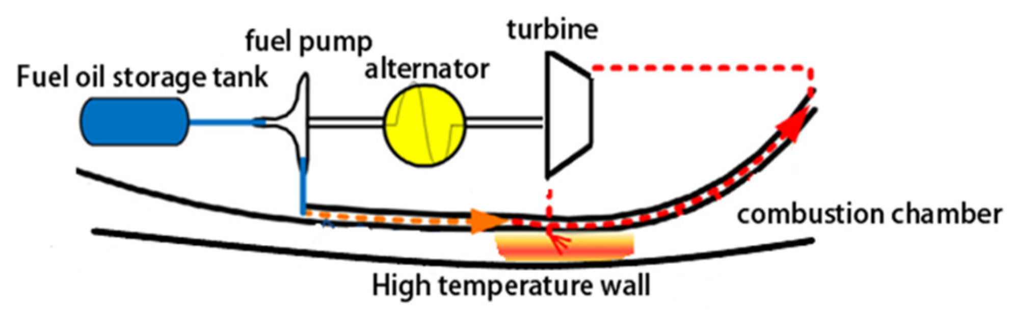
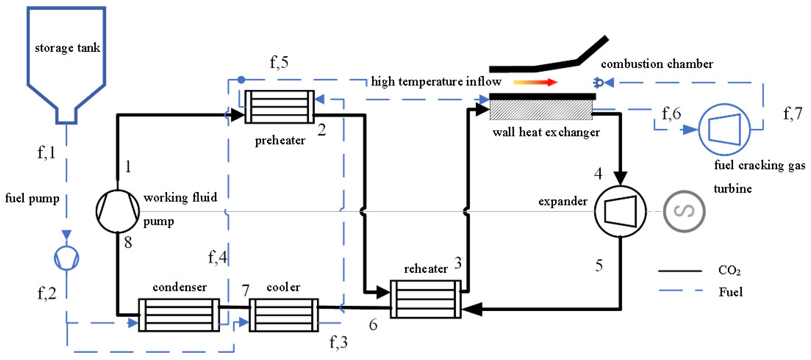
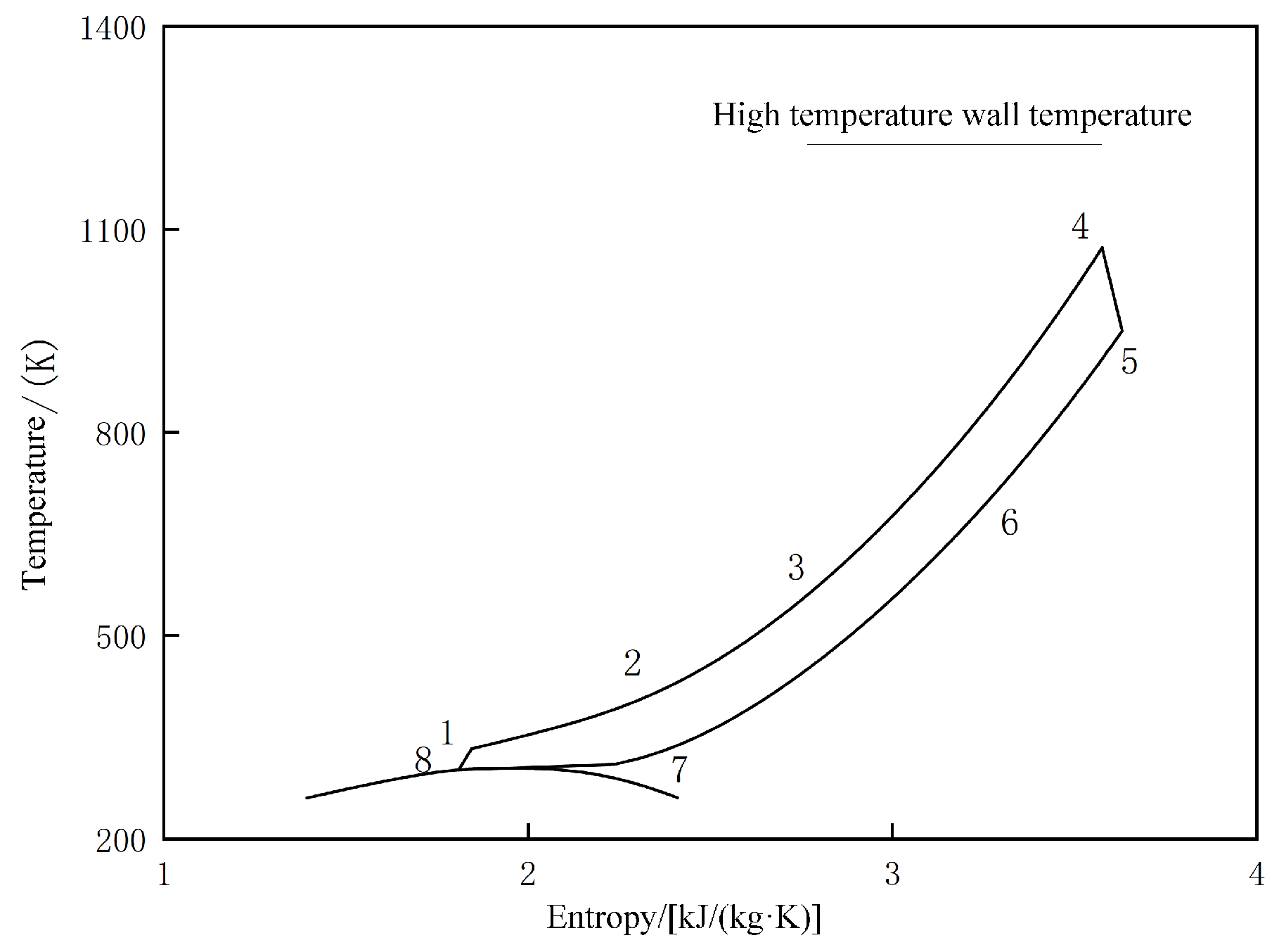
2.1. Working Principle

The storage temperature of hydrocarbon fuel in the tank is generally around 293 K [10,19], which creates a temperature difference for heat exchange with the critical temperature of CO2. However, using the fuel to directly cool CO2 below its critical temperature presents challenges due to poor heat exchange matching, making it difficult to improve thermal efficiency. To address this, a fuel split method was proposed to separately cool and condense CO2, enabling a transition from the supercritical Brayton cycle to the transcritical Brayton cycle under conditions of optimal heat transfer matching. Consequently, a fuel-based CO2 transcritical cooling and power (FCTCP) system is developed. The process schematic is shown in Figure 2, and the corresponding temperature–entropy diagram is illustrated in Figure 3.
As shown in Figure 2, on the CO2 circulation side, since CO2 has already condensed into a liquid phase before compression (at point 8), a working fluid pump is selected as the compression component. CO2 is pressurized from a liquid-phase state below the critical temperature in the working fluid pump and then enters the supercritical zone (8-1). Next, CO2 passes through the preheater, absorbing heat from the fuel at the cooler’s outlet (1-2), and then through the reheater, absorbing heat from the high-temperature CO2 at the outlet of the expander (2-3). It then enters the wall cooling channel of the scramjet engine, absorbing the high-temperature wall heat load and reaching the highest temperature (3-4). At this stage, CO2 has a strong potential to expand, which it transfers to the expander, converting thermal energy into axial work (4-5) to drive the operation of the pump. The CO2 temperature at the expander’s outlet is relatively high. Direct cooling with fuel would waste high-temperature heat and consume a large portion of the fuel’s heat sink. Therefore, a reheater transfers some of the heat to the low-temperature CO2 on the high-pressure side (5-6). The CO2 is then cooled and condensed by the fuel in the cooler (6-7) and condenser (7-8), completing one working cycle. On the fuel side, the fuel is discharged from the storage tank through the fuel pump (f,1-f,2) and divided into two streams for cooling and condensing CO2 (f,2-f,3 and f,2-f,4), respectively. After absorbing the cooling heat of CO2 in the cooler, the fuel reaches a higher temperature and enters the preheater for further energy coupling with CO2. The fuel coupled with CO2 undergoes combustion chamber wall cooling (f,5-f,6) and expansion work in the turbine (f,6-f,7).

2.2. Thermodynamic Model

2.2.1. Model Establishment

The FCTCP system involves multiple energy-coupling processes, and a thermodynamic model is developed based on the following assumptions:
(1)
The energy exchange between the overall cycle and the external environment is negligible.
(2)
The pressure loss in the pipelines and connections is negligible.
(3)
The fuel consists solely of n-decane, and its thermal properties of the fuel in the wall cooling channels are unrelated to the thermal cracking reaction [7].
The energy-coupling relationship of the CO2 transcritical cycle, in conjunction with the workflow illustrated in Figure 2, establishes thermodynamic models for each working process based on the first law of thermodynamics. The corresponding calculation formulas are provided in Equations (1) to (10).
8-1. f,1-f,2 adiabatic compression:
W p , CO 2 = q m , CO 2 ( h 1 h 8 ) = q m , CO 2 ( h 1 s h 8 ) / η p , CO 2
W p , f = q m , f ( h f , 2 h f , 1 ) = q m , f ( h f , 2 s h f , 1 ) / η p , f
1-2 isobaric preheating:
Q pre = q m , CO 2 ( h 2 h 1 ) = q m , f , cool ( h f , 2 h f , 3 )
2-3, 5-6 isobaric reheating:
Q re = q m , CO 2 ( h 3 h 2 ) = q m , CO 2 ( h 5 h 6 )
3-4, f,5-f,6 isobaric heat absorption:
Q wall , CO 2 = q m , CO 2 ( h 4 h 3 )
Q wall , f = q m , f ( h f , 6 h f , 5 )
4-5 adiabatic expansion:
W e , CO 2 = q m , CO 2 ( h 4 h 5 ) = η e , CO 2 q m , CO 2 ( h 4 h 5 s )
W e , f = q m , f ( h f , 6 h f , 7 ) = η e , f q m , f ( h f , 6 h f , 7 s )
6-7 isobaric cooling:
Q cool = q m , CO 2 ( h 6 h 7 ) = q m , f , cool ( h f , 2 h f , 1 )
7-8 isobaric condensation:
Q cond = q m , CO 2 ( h 7 h 8 ) = q m , f , cond ( h f , 4 h f , 1 )
where the following points are presented:
Q represents the heat exchange capacity of the heat exchanger, kW;
q m represents the mass flow rate, kg/s;
h represents the enthalpy value at the state point, kJ/kg;
W p represents the power consumption of the working medium pump or fuel pump, kW;
W e represents the output power of the expander or turbine, kW;
η p represents the isentropic efficiency of the working medium pump or fuel pump;
η e represents the isentropic efficiency of the expander or turbine.
Subscripts are as follows:
f represents fuel;
CO2 represents carbon dioxide;
Pre represents preheater;
Re represents regenerator;
Wall represents the combustion chamber wall cooling channel;
Cool represents cooler;
Cond represents condenser.
In the thermodynamic model calculation process, the pinch temperature difference method is employed to calculate the heat exchange capacity of the preheater, cooler, and condenser, while the supercritical efficiency method is utilized to calculate the heat exchange capacity of the regenerator. The boundary conditions for the thermodynamic calculation are outlined in Table 1 [6,10,19].

2.2.2. Evaluation Metrics

The novel system employs fuel split cooling and condensation, incorporating a preheating process to enhance the work capacity and thermal efficiency of the cycle while simultaneously reducing the consumption of CO2 in fuel heat sinks. Therefore, the cycle evaluation criteria include the thermal efficiency of the CO2 cycle, the output power, and the consumption of fuel heat sinks, as defined by Equations (11)–(16).
Net output power of CO2 cycle:
W CO 2 = W e , CO 2 W p , CO 2
Thermal efficiency of CO2 cycle:
η = W CO 2 / Q wall , CO 2
Output power per unit mass flow rate of working fluid:
W ˙ = W CO 2 + W f ( 1 + γ ) q m , f
Cooling capacity per unit mass flow rate of working fluid:
Q cool ˙ = Q wall ( 1 + γ ) q m , f
Output power per unit mass flow rate of CO2:
W = W CO 2 / q m , CO 2
Fuel heat sink consumption per unit mass flow rate of CO2:
Q = ( Q cool + Q cond Q pre ) / q m , CO 2
where γ represents the mass flow ratio of CO2 to fuel in FCTCP system.

3. Establishment and Validation of the Steady-State Simulation Model

This section establishes steady-state simulation models for each component of the system to further analyze the steady-state performance of FCTCP system under various operational conditions.

3.1. Steady-State Simulation Model

The steady-state simulation model comprises a scroll expander, a working fluid pump, and multiple heat exchangers. The subsequent sections provide detailed explanations of the model’s development and validation.

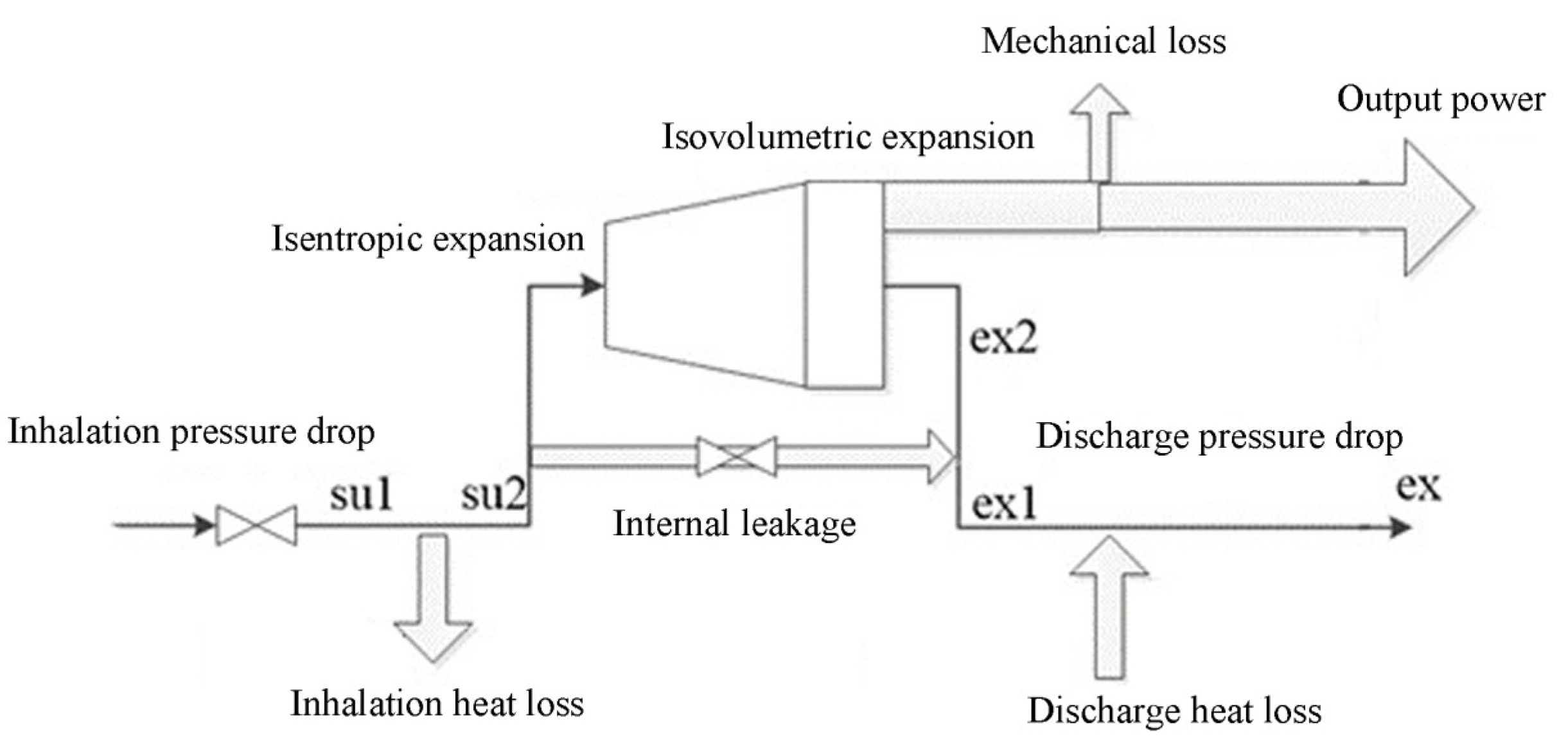
3.1.1. Scroll Expander Model

In this section, the internal working process of the expander is divided into pressure drop in the suction section, heat loss in the suction section, isentropic expansion, and internal leakage for modeling. The schematic diagram of the semi-empirical simulation model is shown in Figure 4.
The model is established in the following section by being provided with the calculation formulas for each work process and the sub-model coefficients that need to be determined.
Isobaric heat loss in the suction section (su1–su2) [20]
Q su = q m ( h su 2 h su 1 ) = [ 1 e A U s u m ˙ c p ] m ˙ c p ( T su 1 T w )
where the following points are presented:
T w is the temperature of the hypothetical wall, °C, calculated according to the average temperature of the working medium at the inlet and outlet of the expander.
A U s u is an empirical parameter.
Energy balance equation under steady state.
The calculation formula for heat loss in the exhaust section is identical to that in the suction section. During steady-state simulation, based on the law of conservation of energy, the scroll expander is governed by Equation (18):
W loss Q ex + Q su = 0
where the following points are presented:
Wloss refers to the loss of output power;
Qex refers to the energy of the outlet section;
Qsu refers to the energy of the inlet section.

3.1.2. Working Medium Pump Model

The working medium pump increases the pressure of CO2 in the transcritical cycle, and its operation is modeled using Equation (19).
q m = η v ρ 8 N V p
where the following points are presented:
η v is the correction factor for the working medium pump;
ρ 8 is the density of the working medium at the pump inlet, kg/m3;
V p is the volumetric efficiency of the pump.
The work consumption of the working medium pump is calculated as follows:
W p = q m Δ h = q m ( h p , out h p , in ) η p
where the following points are presented:
Δh represents the enthalpy difference between the outlet and inlet of the working fluid pump, kJ/kg;
η p denotes the isentropic efficiency of the working fluid pump.

3.1.3. Heat Exchanger Model

In the heat transfer calculation of printed circuit heat exchangers (PCHEs), the heat transfer of CO2 involves both single-phase and two-phase regions, with significant changes in physical properties. This section uses a discrete calculation method and selects heat transfer correlation equations for different heat transfer forms to achieve more accurate calculations of the heat transfer process [21,22,23]. There are many components of hydrocarbon fuel, and the calculation of its flow and thermodynamic characteristics is complex, so n-decane is generally used to replace it [24,25].
The overall heat transfer coefficient in PCHEs is based on the convective heat transfer coefficients of the fluids on the cold and hot sides, denoted as hhot, and hcold, as well as the thermal conductivity of the wall surface, denoted as λ617. The calculation is provided in Equation (21).
U = 1 1 h hot + δ λ 617 + 1 h cold
In the steady-state simulation of the heat exchanger, the PCHE is discretized along the flow direction and calculated using the Logarithmic Mean Temperature Difference (LMTD) method, with the cold and hot fluids undergoing countercurrent heat exchange.

3.2. Model Validation

3.2.1. Validation of the Expander Model

In the genetic algorithm, the optimization objective is to minimize the fitness function value for fitting. The isentropic efficiency is derived from the output power and outlet parameters calculated by the model and then validated against experimental data from the literature to verify the accuracy of the fitted model [26]. The comparison results are presented in Figure 5, showing good consistency between the calculated and experimental values, with errors within ±5%. The results demonstrate that the semi-empirical model, based on the genetic algorithm (GA), can accurately predict the output performance of the scroll expander.

3.2.2. Validation of the Heat Exchanger Model

Experimental data from Saeed et al. [23] were used to compare the outlet parameters of the cold and hot fluids in the PCHEs under identical operating conditions to validate the established steady-state computational model of the PCHEs, as shown in Table 2. The maximum error between the calculated and experimental values was 4.9%.

4. Results and Discussion

4.1. Thermodynamic Analysis

To investigate the impact of various factors on the thermal efficiency of the FCTCP system, the effects of changes in fuel flow rate, wall cooling channel outlet temperature, endothermic pressure, and fuel temperature are analyzed.

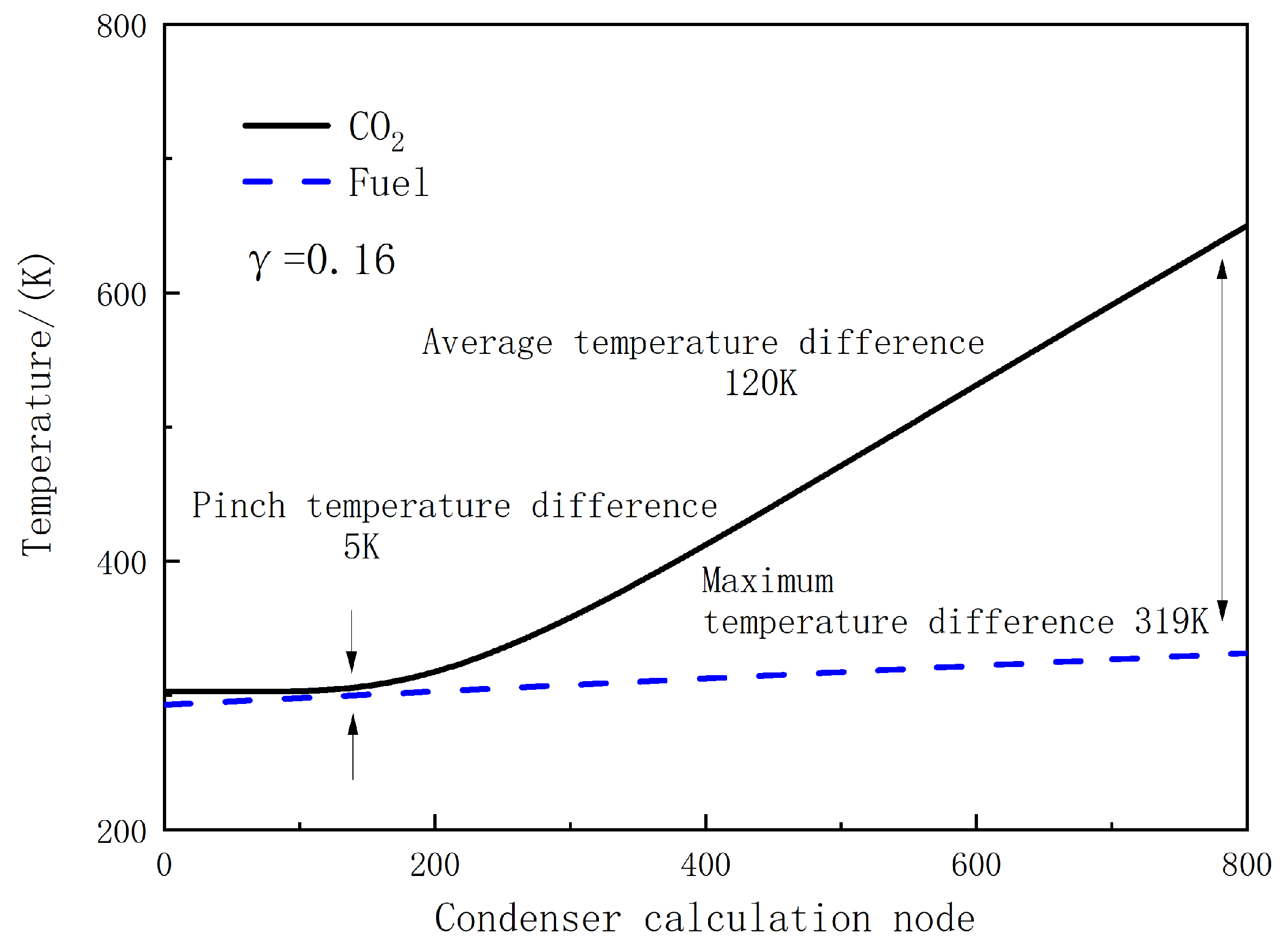
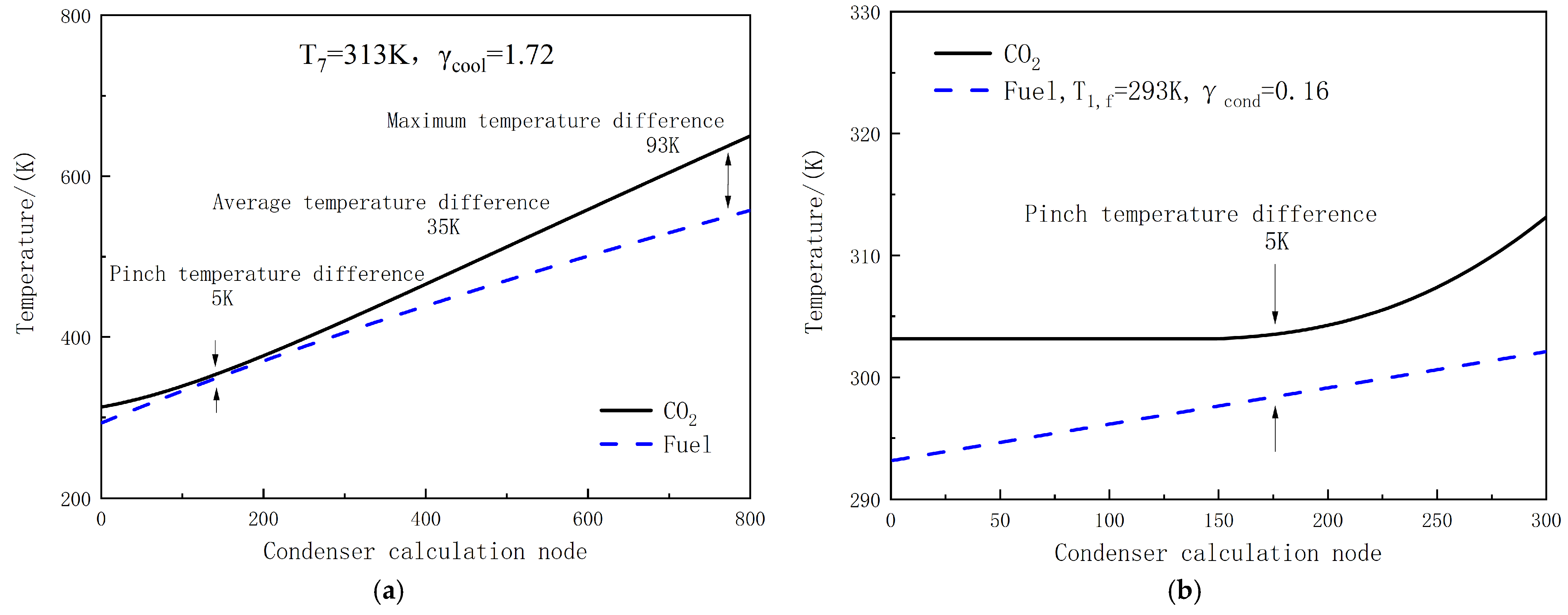
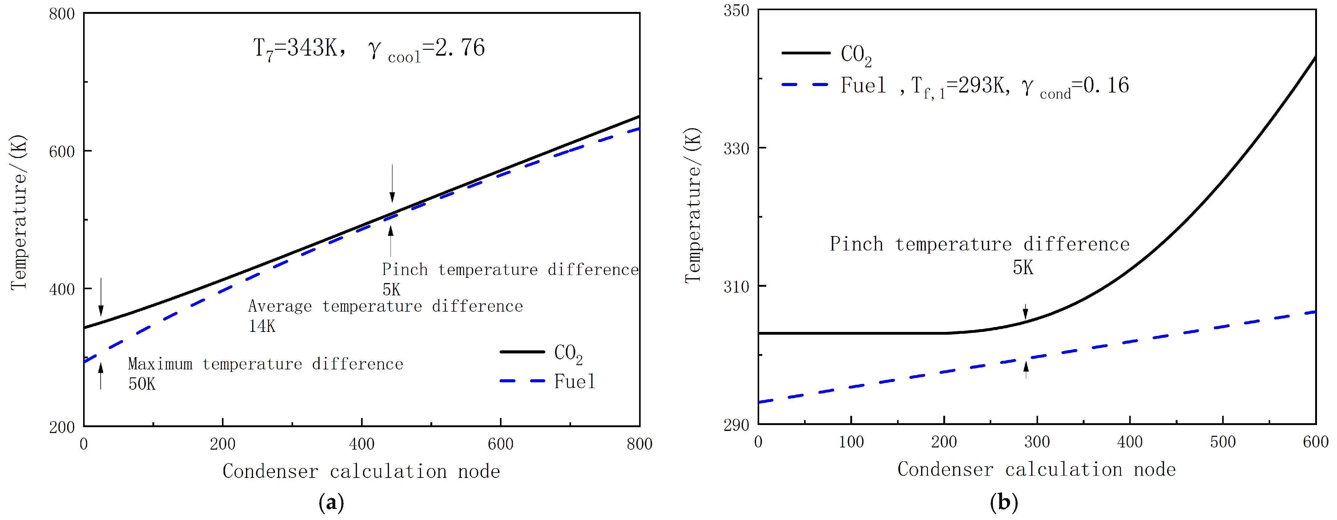
4.1.1. Impacts of a Fuel Flow Rate on the Circulating Cooling Process

The impact of fuel splitting on the thermal efficiency of the CO2 Brayton cycle is first analyzed. If a transcritical cycle is not achieved through fuel splitting, the temperature distribution of CO2 and fuel in the condenser is shown in Figure 6. The inlet temperature of CO2 is set at 650 K, and the flow ratio is calculated to be 0.16, based on a pinch point temperature difference of 5 K. Due to the drastic changes in the specific heat capacity of CO2 near the critical region, its specific heat capacity at the critical point is approximately 2–3 times higher than in the supercritical region, as shown in Figure 7. However, the fuel experiences minimal temperature changes during heat exchange, and its specific heat capacity varies slowly. This mismatch between the specific heat capacities of the fuel and CO2 causes a rapid increase in the heat exchange temperature difference as the CO2 temperature rises. The average temperature difference throughout the entire cooling process is 120 K, with a maximum difference of up to 319 K. This significant disparity leads to poor heat exchange efficiency and high system irreversibility, ultimately resulting in relatively low thermal efficiency of the cycle [17]. Additionally, the fuel temperature after cooling the CO2 is only 331 K, which is insufficient for further energy coupling with CO2 in the preheater.
Consequently, directly condensing CO2 to achieve a transcritical cycle without using fuel splitting is unlikely to enhance the thermal efficiency of the CO2 Brayton cycle or address the issue of high fuel heat sink consumption. Therefore, Figure 8 and Figure 9 show the temperature distribution in the cooler and condenser when fuel split injection is used for cooling and condensing CO2, respectively. In these calculations, the mass flow ratio of CO2 to fuel in the heat exchanger is denoted as γ.
The CO2 temperature T7 at the outlet of the cooler determines the flow ratio in the cooler and the temperature distribution during the cooling process. Figure 8a,b calculate the flow ratio and heat exchange temperature difference in the cooler and condenser when T7 is set at 313 K. The temperature of CO2 at the outlet of the cooler is slightly higher than the critical temperature, and the change in specific heat capacity is small, thus improving the heat exchange compatibility with the fuel. Under the premise of ensuring the pinch temperature difference, the maximum flow ratio of CO2 to fuel in the cooler is determined as γ cool .The fuel outlet temperature rises to 560 K with a maximum temperature difference of 93 K, which is 1.73. The pinch point temperature difference in the condensation process occurs near the saturated vapor-phase point. At the same CO2 condensation and fuel storage temperatures, the flow ratio inside the condenser remains at 0.16, but the temperature variation range within the condenser is reduced, preventing an increase in the heat exchange temperature difference that leads to higher system irreversibility, as shown in Figure 7. Under the CO2 state parameters and flow ratio depicted in Figure 8, fuel split cooling reduces the average heat exchange temperature difference throughout the cooling process to 35 K. This indicates that employing a split-flow approach allows CO2 to achieve a transcritical cycle while improving heat exchange compatibility between CO2 and fuel, thereby enhancing the system’s thermal efficiency. Additionally, because the fuel at the cooler outlet maintains a certain heat exchange temperature difference with the CO2 at the working fluid pump outlet, preheating is feasible. Increasing the design temperature of T7 can further reduce the heat exchange temperature difference in the cooler and raise the fuel outlet temperature. By adjusting the flow diversion ratio and reducing the average heat transfer temperature difference, heat transfer matching can be improved, with a 5 K pinch point temperature difference as the limiting condition. Calculations show that when T7 is set to 343 K, optimal heat transfer matching in the cooler is achieved under a 5 K pinch point temperature difference, as shown in Figure 9.
In Figure 9a, the optimal flow ratio of γcool in the cooler is identified as 2.76, which significantly improves the heat exchange matching between CO2 and fuel. At this flow ratio, the average heat exchange temperature difference during the cooling process is reduced to 14 K, with a maximum temperature difference of 50 K. This improvement occurs because the outlet temperature of CO2 in the cooler is far from the critical point, resulting in a relatively slow change in specific heat capacity, which enables a more efficient heat exchange with the fuel. These findings further confirm that the fuel split-flow cooling method effectively meets the condensation requirements of the CO2 transcritical cycle while optimizing heat transfer during the cooling process. Consequently, the fuel outlet temperature at the cooler increases to approximately 630 K, allowing for greater heat transfer to the CO2 cycle in the preheater. This enhancement improves the cycle’s thermal efficiency and reduces fuel heat sink consumption. Overall, the results demonstrate that employing a fuel split-flow cooling and condensation approach effectively addresses both the condensation needs of the CO2 transcritical cycle and the heat exchange matching requirements during cooling.

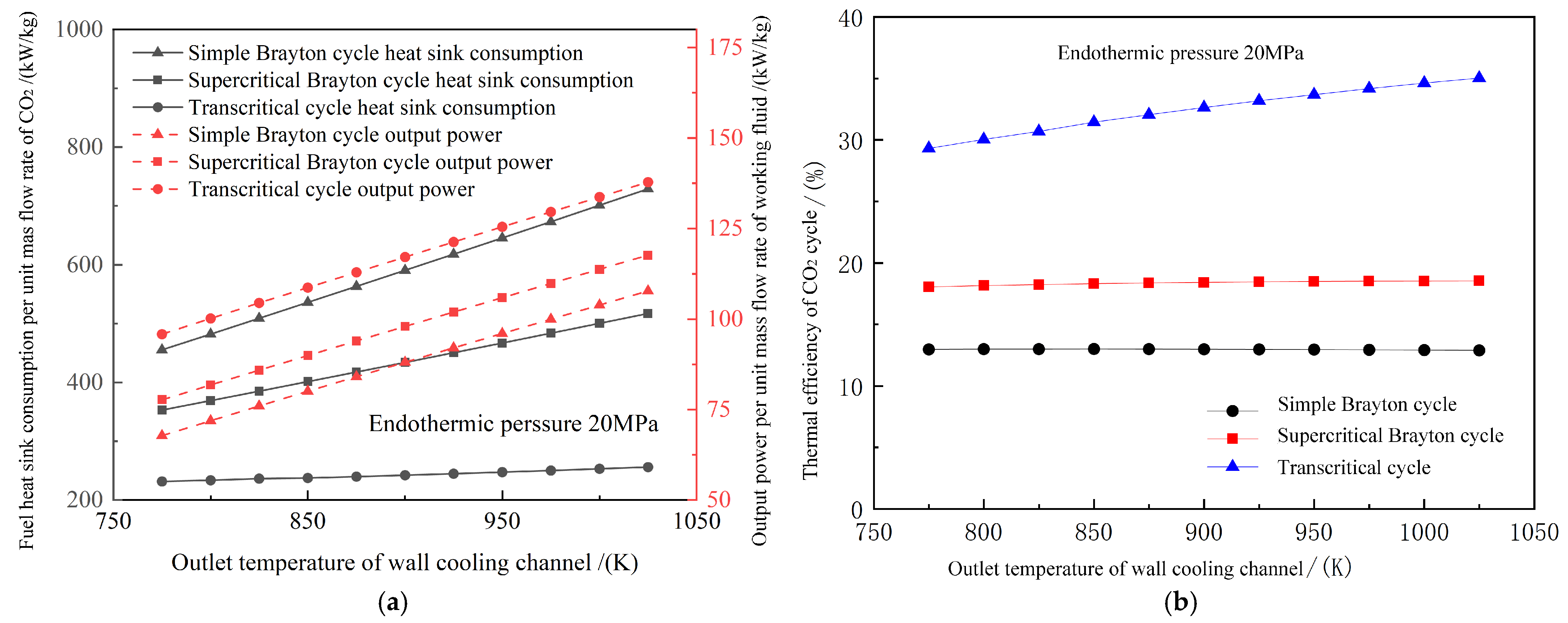
4.1.2. Impacts of a Wall Cooling Channel Outlet Temperature on Performance

In the traditional Brayton cycle, considering the critical temperature and pressure of CO2 are 304.23 K and 7.38 MPa, respectively, the inlet temperature and pressure of the compressor are typically maintained slightly above these critical values to ensure stable operation in the supercritical region. For the supercritical Brayton cycle, the compressor inlet temperature is set at 306.15 K, while for the simple Brayton cycle, it is 311.15 K, with both cycles operating at a pressure of 7.6 MPa. The isentropic efficiency of the compressor is assumed to be 0.8 [27]. Under different flight conditions, scramjet engines are subjected to varying thermal conditions, causing fluctuations in the CO2 temperature at the exit of the wall cooling channel. This section calculates the performance variations in three CO2 cycles as the temperature T₄ ranges from 775 K to 1025 K.
In Figure 10a, the fuel heat sink consumption for all three cycles increases as the outlet temperature of the wall cooling channel rises. This trend occurs because a higher T4 indicates that CO2 absorbs more heat from the high-temperature wall, resulting in an elevated CO2 temperature at the expander outlet. Consequently, more fuel heat sinks are required to cool the CO2 to the desired temperature before it enters the compressor. The transcritical cycle offers an advantage by re-transferring the heat from the high-temperature fuel at the cooler outlet back into the CO2 cycle through preheating, thereby reducing fuel heat sink consumption. As the inlet temperature increases from 775 K to 1025 K, fuel heat sink consumption per unit mass flow rate of CO2 increases by 273 kW/kg and 164 kW/kg for the simple and supercritical cycles, respectively, but only by 24 kW/kg for the transcritical cycle. Furthermore, although the expansion power of CO2 remains the same under identical temperature and pressure conditions, the compression power required after CO2 condensation in the transcritical cycle is reduced by 51.8% compared to in the simple cycle and by 37.7% compared to in the supercritical cycle. As a result, across different T4 values, the transcritical cycle’s output power increases by 27.8% to 41.4% relative to the simple Brayton cycle. Compared to the supercritical Brayton cycle, the transcritical cycle exhibits a substantial performance improvement, with an increase in output power ranging from 17.1% to 23.4%.

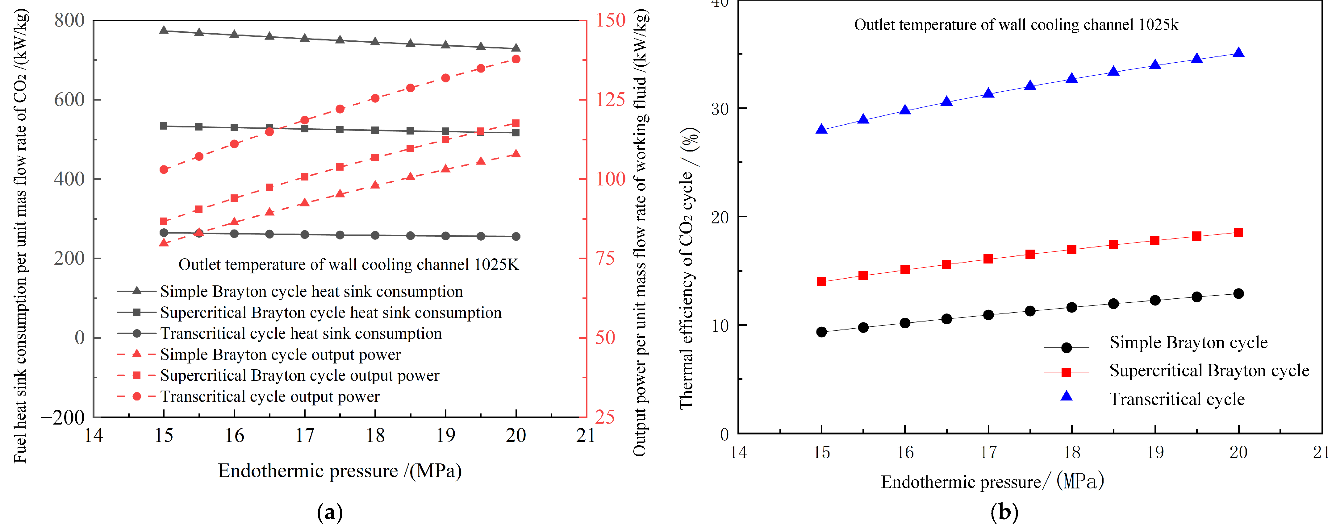
4.1.3. Impacts of an Endothermic Pressure on Performance

Figure 11 shows the performance changes in three CO2 cycles under different endothermic pressures.
The increase in endothermic pressure significantly enhances the work capacity of CO2 in the expander. As illustrated in Figure 11a, the output power of the three cycles generally increases by approximately 35% when the pressure rises from 15 MPa to 20 MPa. Due to the reduction in compression power following the condensation of the working fluid in the transcritical cycle, the output power of the transcritical cycle ranges from 1030 to 1378 kW/kg. In terms of thermal efficiency, the transcritical cycle achieves a thermal efficiency of 28.0% to 35.0%, which is substantially higher than that of both the simple and supercritical cycles. This improvement is primarily because increasing the endothermic pressure elevates the average specific heat capacity of CO2 at constant pressure in the preheater, thereby allowing CO2 to recover more fuel heat. Consequently, the thermal efficiency of the transcritical cycle is more sensitive to changes in endothermic pressure. Specifically, when the inlet pressure rises from 15 MPa to 20 MPa, the cycle’s thermal efficiency increases from 28.0% to 35.0%, which represents an improvement of 171.9% to 199.2% compared to that of the simple Brayton cycle. And compared to that of the supercritical Brayton cycle, the efficiency increase ranges from 88.9% to 100.1%.

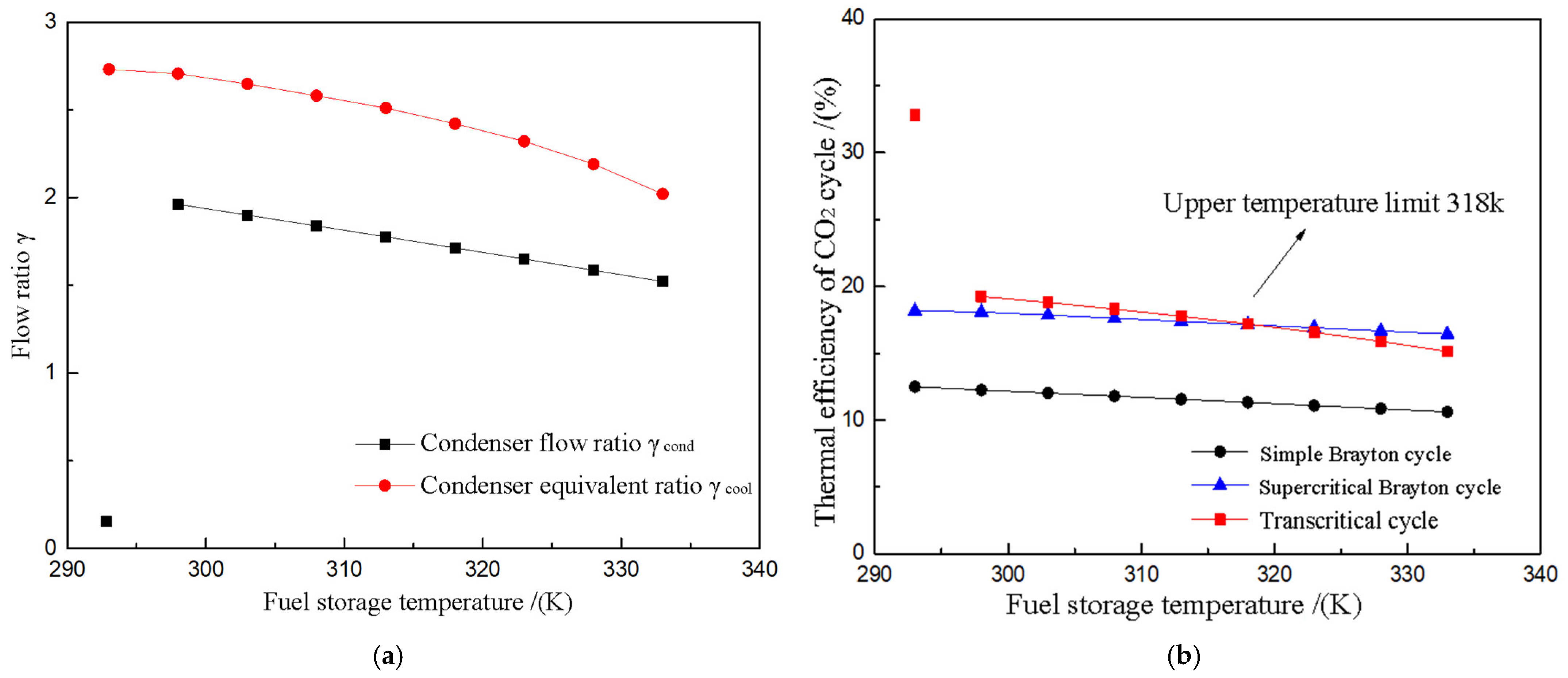
4.1.4. Impacts of Fuel Temperature on Performance

Figure 12 illustrates the changes in CO2 cycle performance when the fuel storage temperature increases from 293 K to 333 K in a high-temperature environment. The additional compression work required by the fuel reduces the thermal efficiency of the CO2 transcritical cycle from 32.8% to 19.2% as the fuel storage temperature rises to 298 K, yet it still outperforms the supercritical and simple Brayton cycles. As the fuel flow in the condenser increases, the compression work on the fuel also rises, consequently lowering the thermal efficiency of the CO2 transcritical cycle until it aligns with the supercritical Brayton cycle at a storage temperature of 318 K. Within the fuel storage temperature range of 298 to 318 K, the thermal efficiency of the CO2 transcritical cycle is up to 6.0% higher than that of the supercritical Brayton cycle, highlighting its advantages within this temperature span.
The analysis demonstrates that the CO2 transcritical cycle, enhanced by integrating a finite fuel heat sink, reduces fuel consumption and improves the work capacity of CO2. As the CO2 endothermic pressure and cooling-stage outlet temperature increase, the enhancement in CO2 cycle thermal efficiency, facilitated by the split cooling condensation and preheating processes, becomes more pronounced.

4.2. Performance Analysis under Steady States

Based on the established steady-state simulation model and performance evaluation criteria, a steady-state simulation analysis was conducted to evaluate the combined cooling and power supply performance of the FCTCP system under varying combustion chamber wall temperatures and fuel flow rates in a scramjet engine. The results were then compared with those of the conventional FVT system and the supercritical Brayton system.

4.2.1. Impacts of Combustion Chamber Wall Temperature on Steady-State Performance

The heat-source condition of the FCTCP system is a critical factor influencing its performance. This study analyzes the combined cooling and power supply performance of the FCTCP system as the combustion chamber wall temperature varies from 950 to 1600 K. The calculations are based on the following assumptions:
(1)
The fuel composition is n-decane.
(2)
The thermal properties of the fuel and the thermal cracking reactions in the wall-cooled channels are unrelated.
(3)
There is no pressure loss in the working fluid flow within the heat exchanger.
Figure 13 shows the cooling capacity of the FCTCP system as a function of the combustion chamber wall temperature under a unit working medium flow. And it is compared with that of the supercritical Brayton and FVT systems. The FCTCP system exhibits a significantly higher cooling capacity per unit mass flow rate of working fluid flow than that of the supercritical Brayton system. Specifically, the heat load per unit mass flow rate of working fluid of the FCTCP system is 75.4% to 80.8% greater than that of the supercritical Brayton system at various combustion chamber wall temperatures. This improvement can be attributed to two main factors: (1) The endothermic process of the CO2 transcritical cycle and the enhanced preheating process extend the endothermic temperature range of CO2 on the high-pressure side, increasing CO2’s heat-carrying capacity at the same wall temperature. (2) The fuel absorbs less heat in the condenser of the FCTCP system. After condensation, CO2 retains a sufficient low-temperature heat sink, and the heat load absorbed at the cooler side is transferred to CO2 in the preheater. Therefore, after fuel mixing, there are more available heat sinks in the wall cooling channel than the Brayton system, and the cooling capacity of the system is also improved.
Figure 14 illustrates the variation in output power per unit mass flow rate of working fluid for the three systems at different combustion chamber wall temperatures. As the temperature of the combustion chamber wall increases, the power output of CO2 and fuel also increases due to greater heat absorption from the combustion chamber wall. This leads to an overall rise in the power generation capacity of all three systems. At lower wall temperatures (950–1200 K), the FCTCP system shows a significantly higher increase in output power per unit mass flow rate of working fluid compared to that of the FVT system, with an increase of 110–164%. The results indicate that, under identical conditions, the FCTCP system achieves the highest thermal efficiency compared to that of other systems.

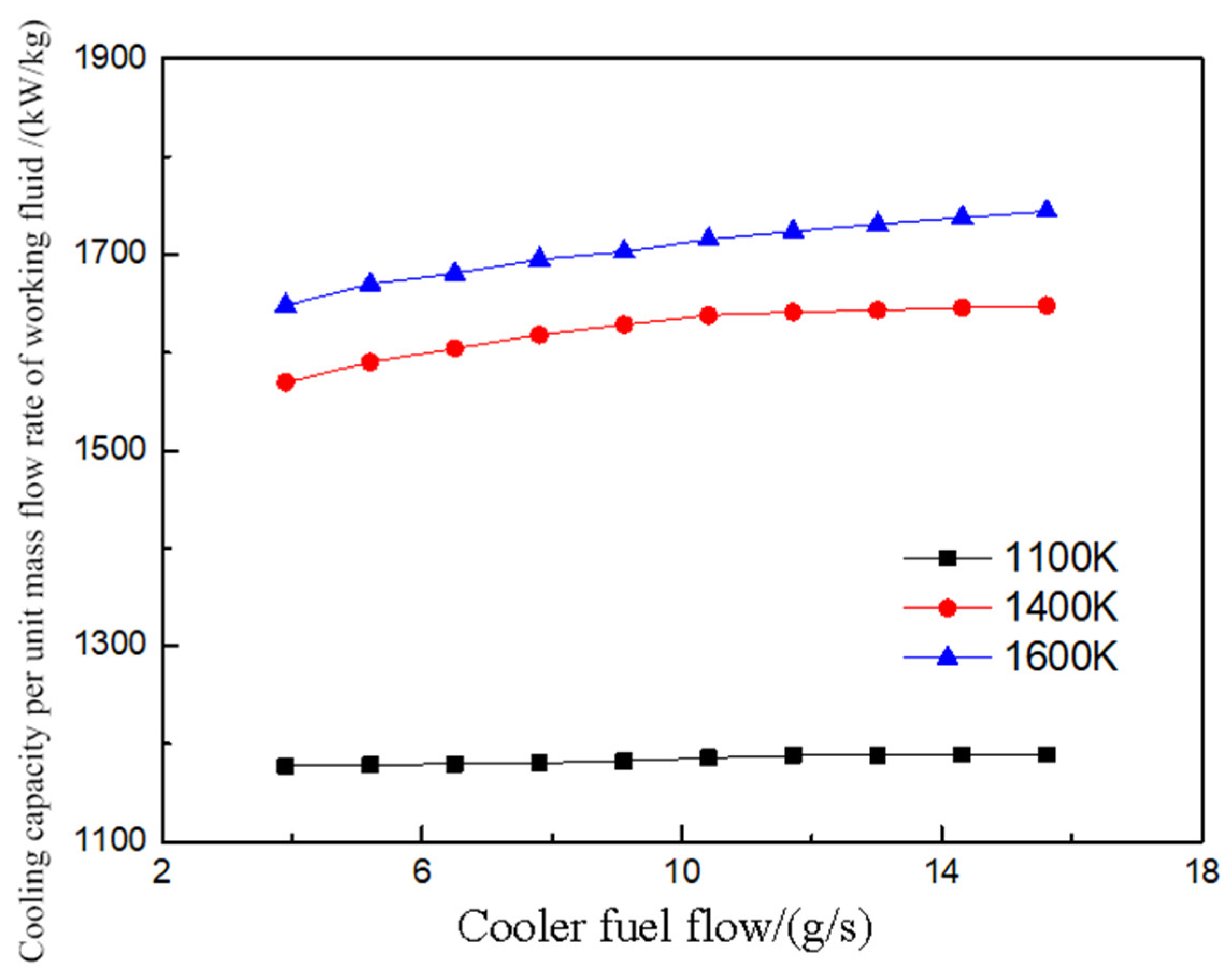
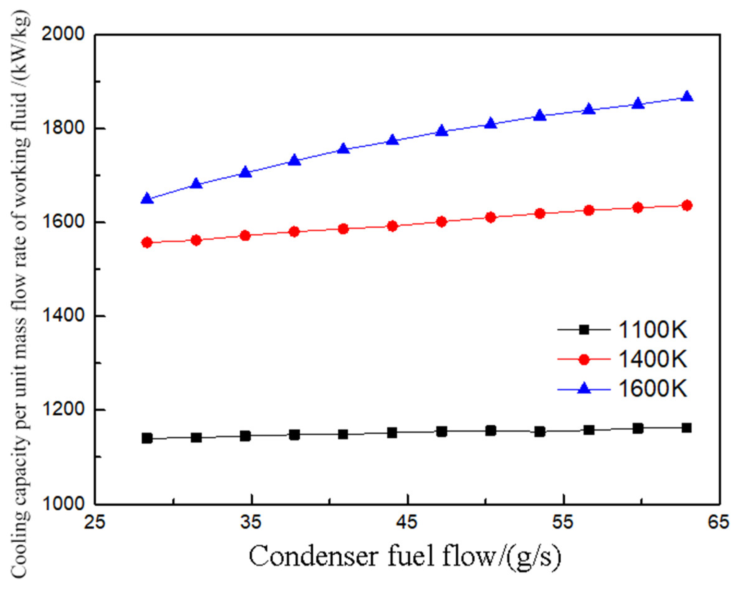
4.2.2. Impacts of Fuel Flow on Steady-State Performance

The working conditions of a hypersonic vehicle dictate that fuel is the sole cold source available for the vehicle. As flight conditions vary, the fuel flow will also change. Research from the previous section indicates that fuel flow significantly affects the cooling and power supply performance of the FCTCP system. Therefore, this section examines how variations in fuel flow within the cooler and condenser impact the system’s combined cooling and power supply performance.
Figure 15 illustrates how the cooling capacity per unit mass flow rate of working fluid in the FCTCP system varies with fuel flow rate in the cooler at different combustion chamber wall temperatures. The calculations are based on wall temperatures of 1100 K, 1400 K, and a maximum of 1600 K. As both the combustion chamber wall temperatures and fuel flow rates increase, the heat transfer efficiency of CO2 and fuel improves, gradually enhancing the cooling capacity per unit mass flow rate of working fluid. At wall temperatures of 1100 K, 1400 K, and 1600 K, the cooling capacity per unit mass flow rate of working fluid of the FCTCP system increases by 1.0%, 4.9%, and 5.8%, respectively, with an increase in fuel flow. These findings indicate that at lower wall temperatures, increasing the fuel flow to the cooler has a modest effect on the system’s cooling capacity, while at higher temperatures, increased fuel flow substantially enhances cooling performance.
Figure 16 presents the output power per unit mass flow rate of working fluid for the FCTCP system at three different combustion chamber wall temperatures. The work capacity of the FCTCP system decreases with increasing working medium flow rates, as the rise in output power is less than the increase in the working medium flow. At the highest wall temperature, the thermal coupling process of CO2 and fuel, as well as the cracking rate, have minimal impact, resulting in a relatively large growth rate of output power. Consequently, despite a continuous increase in flow rate, the output power per unit mass flow rate of working fluid decreases by only 4.7%. At the intermediate wall temperature (1400 K), excessive fuel flow on the cooler side diminishes the preheating effect of the CO2 transcritical cycle and hinders the formation of cracked gas. Therefore, there is a limit to the fuel flow on the cooler side; exceeding this limit causes a rapid decline in work capacity. To further explore the influence of fuel flow on the combined cooling and heating performance of the system, Figure 17 shows the variations in the cooling supply performance of the FCTCP system.
The coupling degree between the fuel in the condenser and the CO2 cycle is relatively low. After condensing CO2, the fuel enters the combustion chamber wall to absorb heat. Consequently, changes in fuel flow rate on the condenser side have a limited impact on the various state points of the CO2 cycle. As shown in Figure 17, the cooling capacity per unit mass flow rate of working fluid in the FCTCP system gradually increases with a rise in fuel flow on the condenser side. Higher combustion chamber wall temperatures improve the heat transfer efficiency of the wall cooling channels, allowing the increased fuel flow to substantially enhance the cooling capacity of the FCTCP system at elevated temperatures. Specifically, at a wall temperature of 1600 K, the cooling capacity per unit mass flow rate of working fluid increased by 13.2% as the fuel flow on the condenser side rose from 28.3 g/s to 62.9 g/s. In contrast, at wall temperatures between 1100 K and 1400 K, the cooling capacity per unit mass flow rate of working fluid increased by only 2.0% to 5.1%. The results indicate that the cooling capacity of the system is significantly enhanced at higher wall temperatures.

5. Conclusions

A novel FCTCP system is presented to address the challenge of limited fuel heat sink of hypersonic aircrafts in this study. The system employs a fuel split cooling approach to facilitate a CO2 transcritical cycle and enhances the cycle’s thermal efficiency through energy coupling between the fuel and CO2 in the preheater. Thermodynamic calculations and comparisons for the CO2 transcritical cycle within the FCTCP system are conducted, followed by the development of a steady-state simulation model. The effects of combustion chamber wall temperatures and fuel flow mass rates on the steady-state combined cooling and power supply of the FCTCP system are analyzed. The main research findings are as follows:
(1) Thermodynamic results indicate that the fuel split cooling approach effectively reduces the average heat transfer temperature difference from 153.4 K to 16 K, significantly improving the heat exchange temperature matching between CO2 and fuel, and thereby reducing the system’s heat exchange losses. The thermal efficiency of the CO2 transcritical cycle reaches 25.2% to 32.8% under varying expander inlet temperatures and endothermic pressures, representing improvements of 54.5% to 80.9% over the supercritical Brayton cycle and 111.6% to 161.9% over the simple Brayton cycle.
(2) Steady-state simulation results show that, across various combustion chamber wall temperatures, the FCTCP system enhances cooling capacity by 75.4% to 80.8% and increases power generation by 12.9% to 51.6% compared to that of the supercritical Brayton system. The output power per unit mass flow rate of working fluid increases by 110% to 164% compared to that of the FVT system, demonstrating a significant improvement in the power generation of the FCTCP system over both the FVT system and the supercritical Brayton system.
(3) Steady-state simulation results indicate that increasing the fuel mass flow rate significantly enhances the cooling capacity of the FCTCP system at higher wall temperatures. At combustion chamber wall temperatures between 1100 K and 1400 K, the cooling capacity per unit mass flow rate of the working fluid increases by 2.0% to 5.1% when the fuel mass flow rate on the condenser side rises from 28.3 g/s to 62.9 g/s. At 1600 K, the cooling capacity per unit mass flow rate of the working fluid increases by 13.2% under the same conditions. Higher combustion chamber wall temperatures improve the heat transfer efficiency of the wall cooling channels, allowing the increased fuel flow to significantly enhance the cooling capacity of the FCTCP system at elevated temperatures.
This study provides a detailed theoretical analysis of the FCTCP system concept for combined cooling and power generation in hypersonic aircraft, highlighting the benefits of this novel system and proposing a new approach for future hypersonic aircraft development. However, current research on this concept has certain limitations, such as the stringent cold source temperature requirements for the FCTCP system. Future studies should focus on analyzing and evaluating the implementation of the FCTCP system across various ambient temperatures and cycle design parameters to determine whether the transcritical cycle retains its advantages.

Author Contributions

Conceptualization, Y.H.; methodology, Y.H. and Q.C.; validation, L.W.; formal analysis, L.W. and Q.C.; data curation, L.W.; writing—original draft preparation, J.D., L.W. and Q.C.; writing—review and editing, Y.H.; supervision, Y.H. All authors have read and agreed to the published version of the manuscript.

Funding

This research was funded by the Key Research and Development Program in Zhejiang Province (No. 2023C01251).

Data Availability Statement

The original contributions presented in the study are included in the article, further inquiries can be directed to the corresponding author.

Conflicts of Interest

The authors declare no conflict of interest.

Abbreviations

Nomenclature
FCTCPfuel-based CO2 transcritical cooling and power system
FVTFuel Vapor Turbine
PCHEprinted circuit heat exchanger
S-CO2supercritical CO2
ORCorganic Rankine cycle
Subscript
condcondenser
coolcooler
cricritical state
ddesign parameter
eexpansion process of expansion chamber
exexpander outlet section
ffuel
lossloss
pworking fluid pump
prepreheater
reregenerator
suexpander inlet section
wallcombustion chamber wall
coldcold fluid
hothot fluid

References

  1. Becker, J. New Approaches to Hypersonic Aircraft; NASA Langley Research Center: Hampton, VA, USA, 1970. [Google Scholar]
  2. Feng, Y.; Qin, J.; Bao, W.; Yang, Q.; Huang, H.; Wang, Z. Numerical analysis of convective heat transfer characteristics of supercritical hydrocarbon fuel in cooling panel with local flow blockage structure. J. Supercrit. Fluids 2014, 88, 8–16. [Google Scholar] [CrossRef]
  3. Zhang, S.; Feng, Y.; Zhang, D.; Jiang, Y.; Qin, J.; Bao, W. Parametric numerical analysis of supercritical cooling in hydrogen-fueled scramjet engines. Int. J. Hydrog. Energy 2016, 41, 10942–10960. [Google Scholar] [CrossRef]
  4. Segal, C. The Scramjet Engine: Processes and Characteristics; Cambridge University Press: Cambridge, UK, 2009. [Google Scholar]
  5. Li, H.W.; Liu, Y.C.; Gan, J.Z. A Comprehensive Review of research on combined cooling and power supply technology for hypersonic vehicles. Guid. Missile 2021, 12, 63–68. (In Chinese) [Google Scholar] [CrossRef]
  6. Cheng, K.L. Performance Study of Combined Power Generation System for Hypersonic Aircraft Based on Cold Source Cascade Utilization. Ph.D. Thesis, Harbin Institute of Technology, Harbin, China, 2020. (In Chinese). [Google Scholar] [CrossRef]
  7. Zhang, D.; Bao, W.; Qin, J. Performance Assessment of Oil-Gas Turbine for Hydrocarbon-fueled Supersonic Combustion Ramjet Engine. Propuls. Technol. 2013, 34, 1708–1712. (In Chinese) [Google Scholar] [CrossRef]
  8. Ma, Z.; Zhang, X.J.; Yang, C.X. Brayton Thermoelectric Conversion Technology for Thermal Protection of Hypersonic Aircraft. Tactical Missile Technol. 2014, 4, 20–25. (In Chinese) [Google Scholar] [CrossRef]
  9. Bao, W.; Qin, J.; Yu, D.R. Reheat Closed Brayton Cooling Cycle System for Supersonic Combustion Ramjet Engines. CN101576024B, 5 January.
  10. Jiang, P.X.; Zhang, F.Z.; Xu, R.N. Integrated System for Thermal Protection and Power Generation of Hypersonic Aircraft Engine. J. Aeroengine 2021, 36, 1–7. (In Chinese) [Google Scholar] [CrossRef]
  11. Hou, S.Y.; Yang, Q.G. Multi-objective optimization of supercritical CO2-organic Rankine combined cycle. J. Power Eng. 2024, 44, 658–664. (In Chinese) [Google Scholar] [CrossRef]
  12. Ahn, Y.; Bae, S.J.; Kim, M.; Cho, S.K.; Baik, S.; Lee, J.I.; Cha, J.E. Review of supercritical CO2 power cycle technology and current status of research and development. Nucl. Eng. Technol. 2015, 47, 647–661. [Google Scholar] [CrossRef]
  13. White, M.T.; Bianchi, G.; Chai, L.; Tassou, S.A.; Sayma, A.I. Review of supercritical CO2 technologies and systems for power generation. Appl. Therm. Eng. 2021, 185, 116447. [Google Scholar] [CrossRef]
  14. Habibollahzade, A.; Petersen, K.; Aliahmadi, M.; Fakhari, I.; Brinkerhoff, J. Comparative thermoeconomic analysis of geothermal energy recovery via super/transcritical CO2 and subcritical organic Rankine cycles. Energy Convers. Manag. 2022, 251, 115008. [Google Scholar] [CrossRef]
  15. Guo, Y.; Guo, X.; Wang, J.; Li, Z.; Cheng, S.; Wang, S. Comprehensive analysis and optimization for a novel combined heating and power system based on self-condensing transcritical CO2 Rankine cycle driven by geothermal energy from thermodynamic, exergoeconomic, and exergoenvironmental aspects. Energy 2024, 300, 131581. [Google Scholar] [CrossRef]
  16. Song, J.; Li, X.; Ren, X.; Tian, H.; Shu, G.; Gu, C.; Markides, C.N. Thermodynamic and economic investigations of transcritical CO2-cycle systems with integrated radial-inflow turbine performance predictions. Appl. Therm. Eng. 2020, 165, 114604. [Google Scholar] [CrossRef]
  17. Kim, Y.M.; Sohn, J.L.; Yoon, E.S. Supercritical CO2 Rankine cycles for waste heat recovery from gas turbine. Energy 2017, 118, 893–905. [Google Scholar] [CrossRef]
  18. Chang, L. Theoretical exploration of CO2 power cycle for waste heat recovery of internal combustion engine. Master’s Thesis, Tianjin University, Tianjin, China, 2018. (In Chinese). [Google Scholar]
  19. Tang, M. Performance Simulation and Optimization Design Research of Thermal Management System for Supersonic Aircraft. Master’s Thesis, Nanjing University of Aeronautics and Astronautics, Nanjing, China, 2017. (In Chinese). [Google Scholar]
  20. Giuffrida, A. Modelling the performance of a scroll expander for small organic Rankine cycles when changing the working fluid. Appl. Therm. Eng. 2014, 70, 1040–1049. [Google Scholar] [CrossRef]
  21. Baik, S.; Kim, S.G.; Lee, J.; Lee, J.I. Study on CO2–water printed circuit heat exchanger performance operating under various CO₂ phase for S-CO₂ power cycle application. Appl. Therm. Eng. 2017, 113, 1536–1546. [Google Scholar] [CrossRef]
  22. Wang, R. Research on Dynamic Characteristics and Control Strategies of CO2 Mixed Refrigerant Power Cycle. Master’s Thesis, Tianjin University, Tianjin, China, 2019. (In Chinese). [Google Scholar] [CrossRef]
  23. Saeed, M.; Kim, M. Thermal-hydraulic analysis of sinusoidal fin-based printed circuit heat exchangers for supercritical CO2 Brayton cycle. Energy Convers. Manag. 2019, 193, 124–139. [Google Scholar] [CrossRef]
  24. Sun, H.; Qin, J.; Li, H.; Huang, H.; Yan, P. Research of a combined power and cooling system based on fuel rotating cooling air turbine and organic Rankine cycle on hypersonic aircraft. Energy 2019, 189, 116183. [Google Scholar] [CrossRef]
  25. Xu, Q.; Li, H.; Feng, Y.; Li, X.; Ling, C.; Zhou, C.; Qin, J. Dynamic thermo-physical characteristics of high temperature gaseous hydrocarbon fuel thermal power generation for regeneratively cooled hypersonic propulsion system. Energy 2020, 211, 118722. [Google Scholar] [CrossRef]
  26. Kohsokabe, H.; Koyama, M.; Tojo, K.; Matsunaga, M.; Nakayama, S. Performance Characteristics of Scroll Expander for CO2 Refrigeration Cycles: 2008 Purdue Conferences. In Proceedings of the 19th International Compressor Engineering Conference at Purdue & 12th International Refrigeration and Air-Conditioning Conference at Purdue [CD-ROM], West Lafayette, IN, USA, 14–17 July 2008. [Google Scholar]
  27. Miao, H.Y. Research on Thermoelectric Conversion System for Supersonic Combustion Ramjet Engine based on Supercritical Carbon Dioxide Cycle. Ph.D. Thesis, National University of Defense Technology, Changsha, China, 2021. (In Chinese). [Google Scholar] [CrossRef]
Figure 1. Schematic diagram of fuel-cracking gas turbine system.
Energies 17 04853 g001
Figure 2. Schematic diagram of the FCTCP system.
Energies 17 04853 g002
Figure 3. Temperature–entropy diagram of the FCTCP system.
Energies 17 04853 g003
Figure 4. Schematic diagram of a semi-empirical model of the scroll expander.
Energies 17 04853 g004
Figure 5. Validation of isentropic efficiency for scroll expander.
Energies 17 04853 g005
Figure 6. Temperature distribution of the heat exchange process between fuel and CO2 during direct condensation.
Energies 17 04853 g006
Figure 7. Change in specific heat capacity at constant pressure of CO2 during heat exchange process.
Energies 17 04853 g007
Figure 8. Temperature distribution inside the heat exchanger at T7 = 313 K. (a) Cooler. (b) Condenser.
Energies 17 04853 g008
Figure 9. Temperature distribution inside the heat exchanger at T7 = 343 K. (a) Cooler. (b) Condenser.
Energies 17 04853 g009
Figure 10. Variation in cycle performance under different wall cooling channel outlet temperatures. (a) Fuel heat sink consumption and output power. (b) Thermal efficiency.
Energies 17 04853 g010
Figure 11. Changes in performance under different endothermic pressures. (a) Fuel heat sink consumption and output power. (b) Thermal efficiency.
Energies 17 04853 g011
Figure 12. Impacts of fuel temperature on performance. (a) Change in flow ratio under different fuel storage temperatures. (b) Variation in thermal efficiency under different fuel storage temperatures.
Energies 17 04853 g012
Figure 13. Comparison of cooling capacity per unit mass flow rate of working fluid in the various systems.
Energies 17 04853 g013
Figure 14. Comparison of output power per unit mass flow rate of working fluid in the various systems.
Energies 17 04853 g014
Figure 15. Variation in cooling capacity per unit mass flow rate of working fluid in the cooler of FCTCP system.
Energies 17 04853 g015
Figure 16. Variation in output power per unit mass flow rate of working fluid in the cooler of FCTCP system.
Energies 17 04853 g016
Figure 17. Variation in cooling capacity per unit mass flow rate of working fluid in the condenser of FCTCP system.
Energies 17 04853 g017
Table 1. Thermodynamic boundary conditions.
NameNumerical ValueUnit
Fuel storage temperature293K
Fuel storage pressure101kPa
Fuel operating pressure3MPa
CO2 condensation temperature303K
Condenser pinch temperature difference5K
Temperature difference at the cooler pinch point5K
Temperature difference at the pinch point of the preheater20K
Efficiency of the regenerator0.4
Isentropic efficiency of working medium pump0.9
Isentropic efficiency of fuel pump0.6
Isentropic efficiency of fuel turbine0.9
Expansion machine isentropic efficiency0.85
Table 2. Validation of the PCHE model.
Input
Parameter
Hot SideCold Side
Pressure (kPa)Temperature (K)Mass flow rate (kg/s)Pressure (kPa)Temperature (K)Mass flow rate (kg/s)
2520553.05150.288353381.05327.81
Output
Parameter
Hot Side Temperature Difference(K)Cold Side Temperature Difference(K)
Experimental valueCalculated valueError (%)Experimental valueCalculated valueError (%)
161.5169.44.90141.1147.84.70
Disclaimer/Publisher’s Note: The statements, opinions and data contained in all publications are solely those of the individual author(s) and contributor(s) and not of MDPI and/or the editor(s). MDPI and/or the editor(s) disclaim responsibility for any injury to people or property resulting from any ideas, methods, instructions or products referred to in the content.

