Review

Return-Temperature Reduction at District Heating Systems: Focus on End-User Sites

by
Hakan İbrahim Tol
1,2 and
Habtamu Bayera Madessa
3,*
1
Unit Energy Technology, Flemish Institute for Technological Research (VITO NV), Boeretang 200, 2400 Mol, Belgium
2
Thermal Systems Unit, EnergyVille, Thor Park 8300, 3600 Genk, Belgium
3
Department of Built Environment, Oslo Metropolitan University, 0130 Oslo, Norway
*
Author to whom correspondence should be addressed.
Energies 2024, 17(19), 4901; https://doi.org/10.3390/en17194901
Submission received: 30 August 2024 / Revised: 20 September 2024 / Accepted: 26 September 2024 / Published: 30 September 2024
(This article belongs to the Section G: Energy and Buildings)

Abstract

:
This review presents a comprehensive examination of recent advancements and findings related to return-temperature reduction in District Heating (DH) systems, with a focus on enhancing overall system efficiency at end-user sites. The review categorizes and clarifies various return-temperature reduction techniques, emphasizing aspects such as building energy performance, heat emitters, thermostatic radiator valves, and substation units. One shall note that return temperature is not a parameter that can be directly controlled within a DH system; instead, it is influenced indirectly by adjusting various system parameters throughout the design, commissioning, operation, and control phases. Key insights include the direct impact of heat demand on return temperatures; the pivotal role of indoor heating systems in optimizing thermal energy use in relation to heat demand; the significance of thermostatic radiator valves in regulating heat output and maintaining low return temperatures; the advantages of ventilation radiators and add-on fans in enhancing radiator efficiency; the necessity for effective substation operation to improve system cooling capacity; and the critical role of operational control strategies in achieving optimal system performance. These findings underscore the need for integrated approaches in DH system design and operation to achieve lower return temperatures and improve overall system efficiency.

Graphical Abstract

1. Introduction

District Heating (DH), with its simple but powerful underlying principle, is a method of distributing heat produced from one or multiple sources to numerous end-user buildings and industrial facilities within the same district via a distribution piping network. This centralized approach to heating supply not only consolidates heat generation but also optimizes the delivery of thermal energy across a wide area, ensuring consistent and reliable heating service to diverse consumers [1,2].
The economic viability of DH systems becomes evident when their inherent advantages, such as higher overall system efficiency and lower environmental impact, are appropriately reflected in the heat market, especially when compared to alternative heating infrastructures or individual heating systems [3].
DH technology stands out as one of the most effective, dependable, and sustainable methods to amplify the use of renewable energy sources and recover energy from industrial waste. The centralized nature of DH systems allows for the incorporation of diverse energy inputs, ranging from biomass and geothermal energy to excess heat from industrial processes, thereby promoting a circular economy. This flexibility in energy sourcing underscores the potential of DH systems to adapt to varying energy landscapes and policy frameworks, ensuring long-term resilience and sustainability [4].

1.1. Background

The fundamental principle of DH operation is based on utilizing sensible heat, a form of energy derived from temperature changes, as the medium to transport and deliver heat to end-users. This principle has driven the development and implementation of DH systems across various regions, providing a reliable and efficient method for heat distribution [5].
A significant trend in the evolution of DH technology is the progressive lowering of temperature levels, encompassing both supply and return temperatures. This trend has evolved across various generations of DH systems, from the steam-based first generation to the low-temperature water-based fourth generation, and now even encompassing the fifth generation, which integrates both heating and cooling. Lowering temperature levels increases the overall system energy efficiency, facilitates the use of low-grade energy sources that would otherwise remain untapped, and aligns with the low-energy demands of future building stocks in a sustainable manner [6].
The return temperature, in particular, serves as a crucial indicator of the overall system efficiency. It reflects how effectively the supplied heat is utilized, essentially indicating the improvement in the cooling of the heating water or the increased temperature difference achieved [7].
The advantages of maintaining a lower return temperature are manifold. It leads to a reduction in the flow rate through the distribution network, which in turn, allows for smaller pipe diameters and pump units to provide the necessary heat. This not only increases the heat supply capacity but also reduces network heat loss and improves the efficiency at the heat production facility [7,8].

1.2. Problem Statement

Considering DH systems, which are based on a hydronic closed loop in their underlying principle, different parts, components, and parameters within the system affect each other in one or more ways. To ensure the highest level of overall efficiency for the entire system, special attention is needed on the evaluation of the interactive thermal and hydraulic effects of their sub-parts in question [9,10,11].
It is important to note that in any type of DH system, the return temperature is not a parameter that can be adjusted directly but, rather, it is a distinctive signature that depends on input factors such as heat load, supply temperature, flow rate, and heat emitter size together with the design and proper operation of the equipments in the system [10,12].
Despite the critical importance of return-temperature reduction for enhancing the overall efficiency of DH systems, the existing literature lacks a thematic review that consolidates the various factors influencing return temperatures specifically at the end-user level. While individual studies have explored various aspects of this issue, there remains a significant gap in summarizing and clarifying the current understanding of specific topics related to end-user components. A structured overview that organizes and discusses the existing literature around particular themes is necessary to synthesize current knowledge.

1.3. Significance

The code of practice by CIBSE [13] emphasizes the importance of achieving low return temperatures in heat networks, particularly regarding the design or modification of building space heating and domestic hot water systems for both new and existing systems. The correct choice of these systems, together with their control mechanisms, is determinative in the optimal operation of the entire DH system throughout its lifetime. Proper design and control at the initial stages can lead to significant long-term benefits in system efficiency and performance [13].
Crane [14] and the technical report by CIBSE [7] underscore the significance of return temperature in DH applications in the United Kingdom. They highlight the necessity of improvement strategies, including enhanced technical specifications for substations and efficiency measures considered during the design stage of DH systems. The studies show that a design temperature scheme of 80/60 °C could be improved to a new temperature scheme of 80/40 °C for space heating systems and 80/20 °C for domestic hot water production units. This leads to flow rate reductions of 50% and 67%, respectively. Such low flow levels result in smaller pipe dimensions, as expressed in the study as two levels down in the commercially available pipe catalogue, resulting in a 19% average reduction in heat loss [14].
Additionally, there are instances where DH systems operate at temperature schemes of 80/75 °C despite being designed for 80/60 °C. These inefficiencies are often due to inadequate design and improper commissioning of building substations (also known as heat interface units). Reports indicate that reducing the return temperature to 45 °C and lowering the pipe size by two levels can decrease heat loss by 43% due to the consequent reduction in flow rate. More details about this case study can be found on page 13 of [14].

1.4. Literature Review

Several review papers exist on DH systems, primarily focusing on broader aspects of this technology and its evolution, yet none have specifically addressed return-temperature reduction at the end-user site. The majority of prior research in this domain has centred on reviewing the technology and exploring potential enhancements considering both the current state and future stages of DH systems.
Werner [15] provides a comprehensive overview of DH (and district cooling) systems, emphasizing their role in promoting energy efficiency and sustainability. The review delves into technological advancements, policy frameworks, and practices that can enhance the effectiveness of these systems in urban environments.
Mazhar et al. [16] discuss the evolution of DH systems through four generations, underscoring their capacity to integrate low-temperature renewable heat sources, which is vital for reducing greenhouse gas emissions and achieving sustainability goals. The review examines the technical configurations of DH networks across different regions, highlighting regulatory frameworks and economic implications.
Lake et al. [17] explore various case studies on the history, design considerations, and energy sources used in DH (and district cooling) systems. This review highlights the advantages and disadvantages of different energy sources and discusses the economic aspects of implementing district energy systems. The review stresses the importance of informed planning and decision-making to ensure that these systems contribute effectively to future energy supply and environmental goals.
Talebi et al. [18] emphasize various modelling techniques for DH components, focusing on demand prediction and optimization strategies aimed at reducing operational and investment costs while minimizing environmental impacts. Their review identifies several barriers to the expansion of DH systems, including the challenge of maintaining thermal comfort in older infrastructures.
Lund et al. [19] provide a detailed examination of the advancements required for future fourth-generation DH systems. Their review emphasizes upgrading heating systems and improving the operation of distribution grids while outlining the benefits of lower grid losses and the efficient use of low-temperature heat sources.

1.5. Aim, Objective, and Scope

This paper aims to review methodologies and strategies for reducing return temperatures at the end-user level in DH systems. It seeks to synthesize current knowledge by offering a structured overview of the existing literature with the goal of enhancing DH system efficiency through the identification and evaluation of targeted end-user interventions.
The paper’s key objectives include the following:
RO1: Analysing existing research on return-temperature reduction techniques at the end-user site, identifying key themes, methodologies, and findings to build a comprehensive knowledge base.
RO2: Assessing specific end-user interventions, such as building space heating and domestic hot water systems, and their control mechanisms, to determine their impact on return-temperature reduction and overall system efficiency.
RO3: Investigating how the design and operation of end-user heating systems influence return temperatures, including the role of proper commissioning and maintenance.
The scope of this paper is focused exclusively on the end-user site within DH systems, considering it as the final and most determining stage in the heat supply chain. In addition, this review focuses on DH systems within the European context, where centralized heating is prevalent. While centred on European applications, the review acknowledges that the concepts and methodologies discussed may also apply to regions with similar centralized systems. It is important to acknowledge that regional variations may require customized solutions tailored to specific geographical contexts. For example, in China, domestic hot water is predominantly produced using gas water heaters, solar water heaters, or air source heat pump water heaters, rather than through centralized thermal stations (For further details regarding the domestic hot water supply technologies in northern and southern China, please refer to Table 1 of [20]).

1.6. Review Approach

The review approach for this paper involved a systematic and comprehensive search of academic research databases using specific keywords related to the topic of return-temperature reduction in DH systems. The keywords “low return temperature”, “return-temperature reduction”, and “increased temperature difference” were employed to capture a wide array of relevant studies.
The search scope for this review was meticulously defined to include only peer-reviewed journal articles, conference papers, review papers, theses, and editorials published in English. The literature search was conducted using reputable academic databases and sources, including Elsevier, Wiley, Taylor & Francis, IEEE Xplore, and Google Scholar, ensuring a comprehensive coverage of relevant studies. Given the employment period of the author, the review primarily focuses on the literature published up to the year 2018, thereby capturing the state of research and developments pertinent to the topic within this timeframe.
The initial search yielded a substantial number of references, many of which addressed various aspects of DH systems without directly focusing on return temperature. These references, while not directly discussing return-temperature reduction, provided valuable context and extended the breadth of the survey by highlighting interconnected areas of research. Such references were instrumental in understanding the broader implications of DH system design and operation on return temperature.
Following the literature search, a thorough analysis of the obtained papers was conducted. Each paper was carefully reviewed to interpret its methodology and main results, with a particular focus on identifying relevant findings related to the end-user site in DH systems. This process involved a detailed examination of how different studies addressed return temperature, either directly or indirectly, through their discussion of thermal and hydraulic interactions, system efficiency, and operational strategies.
To organize the wealth of information, the refined papers were clustered into relevant topics of interest. This clustering was based on the primary focus areas of the review, which include building stock, indoor heating systems thermostatic radiator valves, and substations as components of the end-user site. By categorizing the papers into these specific topics, the review provides a structured and coherent synthesis of the current state of knowledge (Figure 1).

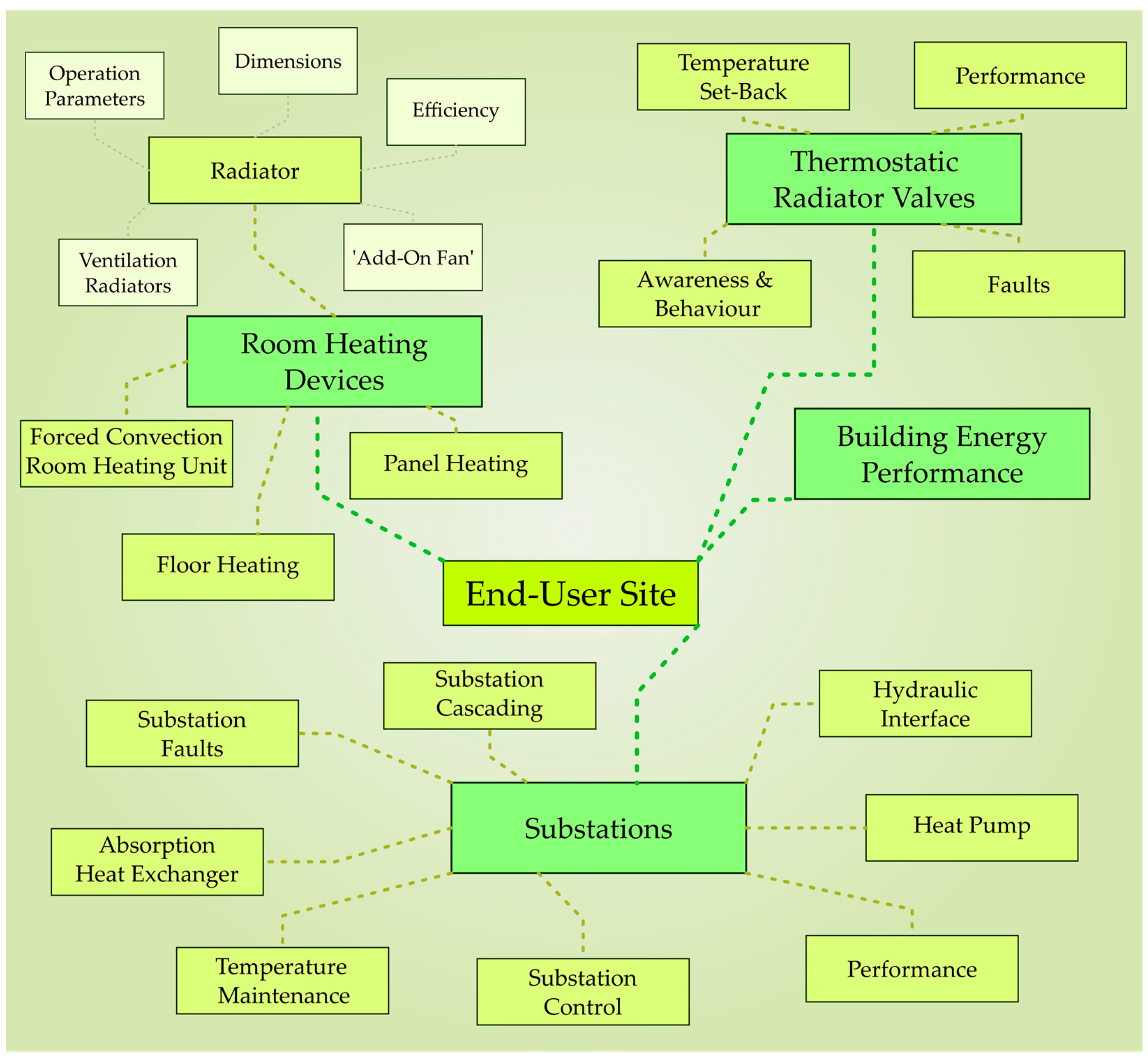
2. Thematic Review and Analysis

This section offers an in-depth examination of key factors influencing return-temperature reductions in DH systems, with a focus on end-user sites. This section systematically explores critical topics, including building energy performance, room heating units, thermostatic radiator valves, and substations, as illustrated in Figure 2.

2.1. Building Energy Performance

Space heating is a primary objective of DH delivery to residential and commercial buildings, significantly influenced by the building’s energy performance, particularly insulation. Improved insulation techniques and energy-efficient design result in lower heat demand, enabling low-temperature operation in space heating systems. This leads to the potential for achieving lower return temperatures under the same supply temperature scheme [1,21,22,23,24]. A reduced heat demand allows for a lower supply temperature to adequately meet heating requirements, as the heat demand directly determines the necessary level of supply temperature [25,26,27].
It is important to highlight how reduced heat demand enables low-temperature operation, which can manifest as a reduction in the supply temperature, return temperature, or both. When the heat demand is lowered (often due to improved insulation of the heated space) the overall heat loss through the building envelope diminishes, thanks to the increased thermal resistance of the building envelope, resulting in less energy being required to maintain the indoor temperature at a set comfort level. Heating demand represents the amount of heat energy required to replace what is lost through the building envelope in order to sustain the desired indoor climate. Therefore, as heat loss decreases, the heating system needs to generate less heat, allowing for the possibility of lowering the system’s operational temperatures while still meeting the building’s thermal needs. Details further given in Section 2.2, how radiator units can operate effectively at lower supply temperatures when heat demand is reduced can be directly tied to the radiator thermal performance, which depends on the radiator thermal characteristics and the mean temperature difference between the radiator and the indoor temperature. The radiator heat output, which essentially equates to the building heat demand, is a function of this mean temperature difference. Because the heat output is governed by the mean temperature difference, altering the supply temperature can still meet the required heat demand, with the return temperature adjusting accordingly. This thermal relationship is the answer to how the heating system functions efficiently at lower temperatures when the heat demand is lowered [23,24,25].
Attention must also be given to prolonged off-peak heating periods associated with lower heat demand levels than the design peak condition. The lowest return temperatures are observed during times of minimal heat demand in similar building types, as noted by [2,10,26,28]. Langendries [8] highlights the benefit of heat gains, such as solar gains, which significantly reduce heat demand and subsequently lower return temperatures. This reduction scales with the level of heat gains, as illustrated in Figures 10–15 of [8].
In a case study in Klagenfurt, Austria, Basciotti et al. [29] investigated how different stages of building-insulation renovation affected return temperature. Each renovation stage resulted in further reductions in return temperature, overall heat demand, and network heat loss. The common retrofitting method led to a 0.3 K decrease in the average DH return temperature, with a standard deviation of 4.1 K locally across various DH network branches. This standard deviation was attributed to differences in building structures and insulation qualities [29].
While not the primary focus of this section on building energy performance, it is important to emphasize that in the context of subsequent sections addressing indoor heating systems, thermal energy retrofitting of existing buildings necessitates a comprehensive review of the heating system. This includes fine-tuning piping components, resetting the mass flow rate, and adjusting the supply temperature to ensure optimal operational performance. These considerations are critical for enhancing system efficiency and achieving desired energy outcomes in retrofitted buildings [27,30].

2.2. Room Heating Devices

In the indoor spaces of buildings, various hydronic (water-based) room heating devices (also known as heat emitters, room heaters, or terminal units), such as radiators, forced convection devices, and underfloor heating systems, are commonly used to provide space heating in DH systems [31,32].
As the final and crucial stage in the heat supply chain of a DH system, indoor heating systems and their operational strategies are paramount for achieving enhanced utilization of delivered thermal energy. This is directly linked to reducing return temperatures and increasing the temperature difference between supply and return [33]. The design and operation of indoor heating systems are essential for achieving the minimum possible return temperature, as emphasized by the CIBSE code of practice [13] and by Trüschel regarding design effects on system performance [12]. During prolonged heating periods, domestic hot water consumption is primarily dominated by space heating, significantly influencing the overall DH return temperature [34].
According to Parsloe [31], optimal heat-emitting devices operate at low supply temperatures and achieve a significant temperature difference between supply and return. The key performance factor for indoor heating systems is the ability of the room heating device to transfer heat efficiently to the indoor space, ideally achieving a return temperature close to the indoor air temperature [31].
A detailed review of various hydronic space heating systems and room heating units, with a focus on performance measures for low-temperature operation in Russian buildings, is provided by Ovchinnikov et al. [35]. Further comparative assessments of low-temperature heating units can be found in [36,37].

2.2.1. Radiators

Given the widespread use of radiators in DH systems [12,27], enhancements in radiator efficiency are of paramount importance, as they can lead to substantial improvements in return temperature and, consequently, overall system efficiency. The selection and configuration of radiator units and indoor heating components are crucial for ensuring thermal comfort while optimizing energy consumption [38].

Radiator Dimensions

The emphasis on radiator dimension primarily addresses the issues of over- and under-sizing in current DH systems. Both scenarios can lead to high return temperatures. Over-sizing may cause overheating due to excessively low flow requirements that are hard to adjust in a high-flow system. Conversely, under-sizing results in inadequate thermal comfort, leading to inefficient operation and high return temperatures [27,39,40,41,42].
Existing radiator units are often reported as over-dimensioned based on current design practices. Several factors contribute to this issue: Firstly, the heat demand is frequently overestimated, such as by selecting an excessively low design outdoor temperature or neglecting heat gain issues. Secondly, the common practice of sizing radiators according to window dimensions aims to prevent discomfort from drafts or air leakage near windows. Additionally, extra safety precautions are sometimes incorporated, and post-design building energy retrofitting can further reveal the need for scaling up radiator sizes [8,13,23,41,42,43,44,45].
Current radiators are generally over-dimensioned by at least 10%, with some cases exceeding 100% [41,42]. Figure 15 in reference [46], as well as Figure 6 in [41], illustrates the variations in radiator dimensions across different heat demand levels.
Oversizing radiators can significantly lower return temperatures and potentially reduce supply temperatures [8,14,26]. For instance, Lauenburg et al. [43] observed that a radiator unit designed with a 100% oversizing at an 80/60 °C temperature scheme effectively operates as if it were designed for a 55/45 °C scheme. Increasing oversizing, whether from initial design or post-renovation adjustments, continuously lowers the return temperature (as shown in Figure 2.15 of [47]). Additionally, Karlsson and Ragnarsson [48] noted the impact of radiator oversizing on water cooling in a geothermal DH system in Iceland (Figure 3).
However, since radiator over-dimensions are set as nominal values, low-flow balancing and reduced supply temperatures must be maintained in the hydronic loop [12,14,23,42]. Zinko et al. [10] also highlight the importance of site-specific optimization and tuning of indoor heating components over merely increasing radiator size.
Furbo and Kristensen [49] analysed a 120 m2 single-family house with a peak heat demand of 3.7 kWth at −12 °C outdoors and 20 °C indoors. They found that well-insulated buildings can be heated with a supply temperature of 45 °C instead of 60 °C when using over-dimensioned radiators. This approach, with minimal marginal cost, resulted in an average yearly return temperature as low as 20 °C with a supply temperature of 45 °C.
Brand and Svendsen [50] proposed replacing existing radiators with larger ones to enable low-temperature operation while avoiding modifications to building heating pipelines. Their approach involves increasing radiator depth while keeping length and height unchanged. In a 1973 non-renovated home, this technique allowed the DH system to maintain a supply temperature below 50 °C throughout the heating season, reducing the weighted mean return temperature from 32.9 °C to 27.6 °C. In an extensively renovated home (see details in [50]), low-temperature radiators enabled year-round operation with a 50 °C supply temperature and a mean return temperature of 24.1 °C.
Ljunggren and Wollerstrand [42] outline a method for quantifying radiator over-dimensioning through theoretical calculations that compare expected and actual results based on flow rates, operational temperatures, and indoor temperature measurements. This method aims to adjust operating parameters to reflect the radiator’s oversizing. For example, a radiator with 100% oversizing can shift from a nominal operation temperature scheme of 80/60 °C to a new scheme of 60/40 °C or 75/34 °C (depending on variable flow control). This adjustment can reduce the return temperature from 60 °C to approximately 40 °C in an indirect substation arrangement. Their study provides detailed results in Table 2 (within this reference), illustrating return-temperature reductions achieved at various levels of oversizing for both radiator dimensions and substation heat exchangers, along with different control strategies [42].
Excessive return temperatures can also stem from undersized radiators. These radiators, with insufficient capacity, often require higher flow rates to maintain indoor temperatures, leading to premature cooling of the heating medium and elevated return temperatures. Consequently, heating systems with constant flow operation might face underheating issues, prompting a potential increase in the supply temperature to address customer complaints [51].
Østergaard and Svendsen [51] developed a method to identify undersized radiators across buildings with varying structures, heated areas, and insulation characteristics with the focus given to evaluate the challenges of adopting low-temperature operation in Danish buildings from the 1930s. Their approach involved detailed analysis at both the room and house levels, factoring in insulation quality, radiator capacity, and occupants’ indoor temperature preferences. They determined the minimum supply temperature required for each radiator to meet local heat demands. The study found that undersized radiators needed higher supply temperatures compared to properly sized ones. Key radiators with substantial negative impacts on overall house return temperatures were identified for replacement. For instance, in two of the analysed homes, replacing inadequate radiators resulted in a reduction of the yearly mean return temperature from approximately 32.2–33.2 °C to 29–28.7 °C. This improvement was observed during 85% of the heating season, while the remaining 15% saw similar return temperatures pre- and post-renovation. The findings underscore the importance of addressing undersized radiators to optimize low-temperature operation and enhance system efficiency [51].
The survey conducted by Jangsten [40] on operational data from various components within the DH system in Gothenburg highlighted the necessity for replacing certain radiators identified as non-oversized with the aim of increasing the overall energy efficiency of the building [46].

Radiator Efficiency

Radiator efficiency significantly impacts return-temperature reduction in DH systems. Enhanced radiator efficiency increases heat output, thereby improving the thermal performance of the system. When radiators operate more efficiently, they transfer heat more effectively to the served space, leading to a more pronounced cooling of the heat carrier medium before it returns to the central heating plant [52]. McIntyre [53] emphasizes that achieving low return temperatures depends on accurate heat output calculations during the design phase.
Appendix A delves into the technical aspects of radiator efficiency, covering heat transfer mechanisms, connection positions, radiation heat transfer, and enclosure effects. These factors are crucial for optimizing radiator performance. Effective heat transfer mechanisms and well-designed connection configurations can substantially improve radiator efficiency. For example, optimal radiator designs and correct connection setups enhance heat transfer rates, thereby boosting overall efficiency.
Figure 4, sourced from [54], depicts return temperature performance across different radiator types and connection schemes under a specific operational scenario. Reports [40,54] indicate that no single connection scheme is universally superior; its effectiveness varies with specific operational conditions.

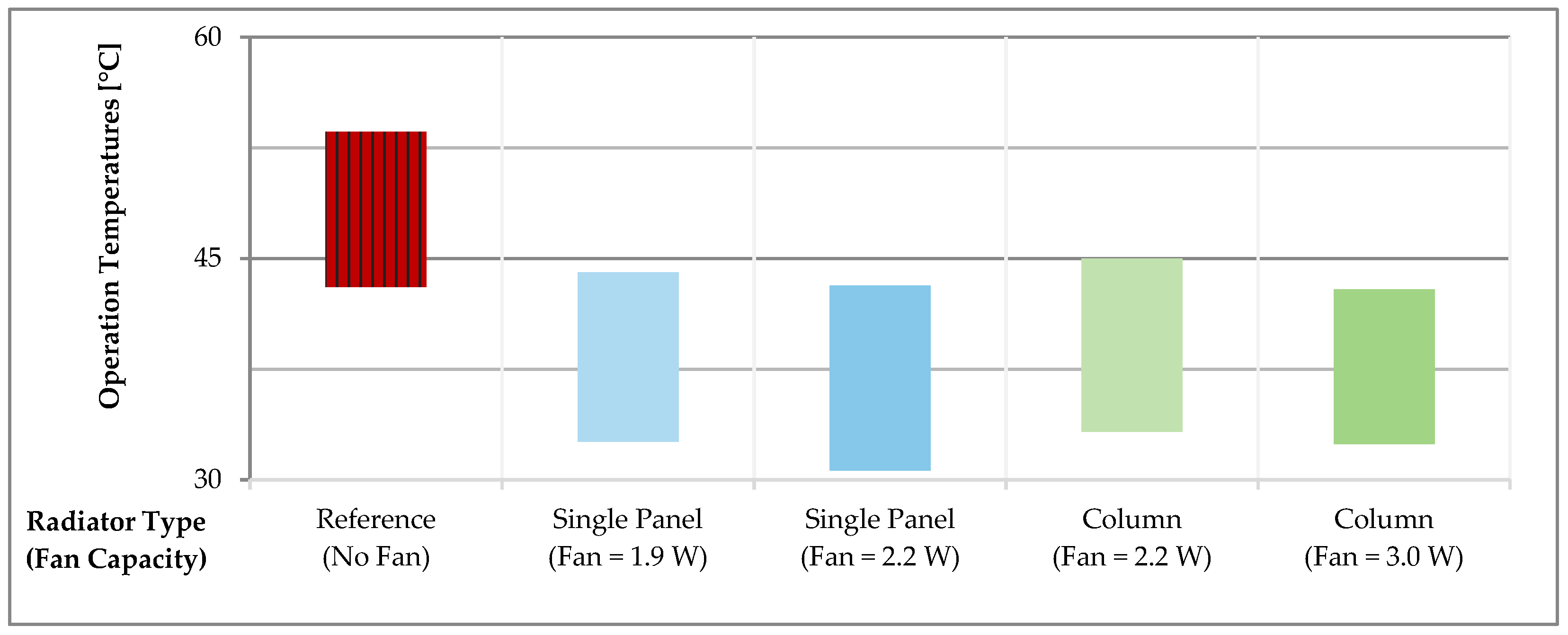
‘Add-On Fans’ and Ventilation Radiators

Conventional radiators primarily rely on natural convection, where air circulates upward as it heats. Adding fans at the radiator’s bottom edges and directing air upward through the radiator channels enhances convective heat transfer, thus increasing the radiator’s overall heat output. This modification shifts from natural to forced convection, leading to improved radiator cooling and more effective heating, while also reducing window cold draughts [22,35,55,56].
Two primary applications arise from this concept. The first involves adding fans to continuously circulate indoor air, known as ‘add-on fans’ [22]. The second, ‘ventilation radiators’, integrates forced outside air through radiator channels [55]. These fan solutions improve performance at low return temperatures and are useful in spaces where larger radiators cannot be installed [56]. Additionally, they offer a cost-effective alternative to replacing undersized radiators in existing systems [22,57].
Johansson et al. [22,57,58,59] examine the performance of add-on fans for radiators. Detailed modelling of radiators with add-on fan systems is discussed in [60]. Preliminary theoretical analyses, as noted in [58], indicate that increasing air speed enhances heat output by improving convection, with supply temperature and mass flow rate held constant at all speeds, as detailed in Table 1. The analysis and subsequent experiments led to a reform of operational settings to prevent overheating. For single-panel and column radiators with heat outputs of 360 Wth and 430 Wth at 60/45 °C, respectively, the reform involved lowering the supply temperature while maintaining a constant water mass flow rate. This adjustment significantly stabilized operational temperature ranges for all radiator types and fan capacities. Figure 5 illustrates the revised supply temperatures and corresponding return temperatures, based on the heat ratio of 0.8 from [58].
This study (based on nominal heat demand values from the graphs given in [58]) investigates the impact of radiator add-on fans on the primary return temperature, specifically within the DH side loop of the space heating heat exchanger in an indirect substation configuration. Regardless of the reform approach —whether maintaining a constant supply temperature or a fixed primary side mass flow rate— both methods resulted in notable reductions in primary return temperature. For the fixed supply temperature approach, a single-panel radiator’s return temperature decreased by 11.7 °C with 2.2 Wel of fan power and by 9.7 °C with 1.9 Wel. A reduction of 11.2 °C was also observed with the fixed mass flow rate approach. In the case of column-type radiators, maintaining a fixed supply temperature led to a return-temperature reduction of 9.7 °C with 3.0 Wel of fan capacity and 7 °C with 2.2 Wel. Similarly, the fixed mass flow rate approach achieved a reduction of 11.2 °C. These results are based on nominal heat demand values, as detailed in the graphs from [58].
Johansson and Wollerstrand [57] further illustrate the impact of reformation operations on operational temperatures, focusing solely on single radiator units without a heat exchanger. Their findings indicate that maintaining constant mass flow while reducing the supply temperature benefits low-temperature operation without compromising the temperature difference. Conversely, the constant supply temperature approach, achieved by lowering the mass flow rate, results in superior temperature differences and significantly lower return temperatures (see Figure 6).
Myhren and Holmberg [55,61,62,63,64] discuss the concept of ‘ventilation radiators,’ which use forced external airflow through radiator channels, similar to add-on fans but with unheated intake air. A comparative study [61] found that ventilation radiators, with an airflow speed of 0.7 m/s and an inlet temperature of −5 °C, provided improved performance over traditional radiators. Specifically, the ventilation radiator achieved a radiator surface temperature 7.8 °C lower and a total heat output 50 Wth less, with an increased convection rate of 10 Wth and decreased radiation by 60 Wth. Further studies [63,64] highlight efficiency improvements with new fin patterns, including a 20% increase in heat output and a 10% increase in ventilation rate due to shorter fin spacing. Notably, the radiator’s heat output improved from 344 Wth to 417 Wth as outdoor temperatures dropped from −7.5 °C to −15 °C [64].
Ploskić and Holmberg [65,66] examine the integration of ventilation with baseboard heating units. They demonstrate that a baseboard heater, measuring 1.55 m in length and supplied at 45 °C, can effectively heat inlet air from −6 °C to 21 °C at a ventilation rate of 7 l/s. For lower temperatures, such as −12 °C, a higher supply temperature of 55 °C and an airflow rate of 10 l/s are required. Additionally, their research on vent convectors reveals their role in pre-heating ventilation air alongside conventional heating units [67], a concept further explored by Mundt et al. [68].
Hesaraki and Holmberg [69] conducted a survey indicating that occupants with ventilation radiators report superior comfort compared to those using under-floor heating systems. Furthermore, the installation of ventilation radiators can reduce the tendency of occupants to open windows for ventilation in warm conditions [70].

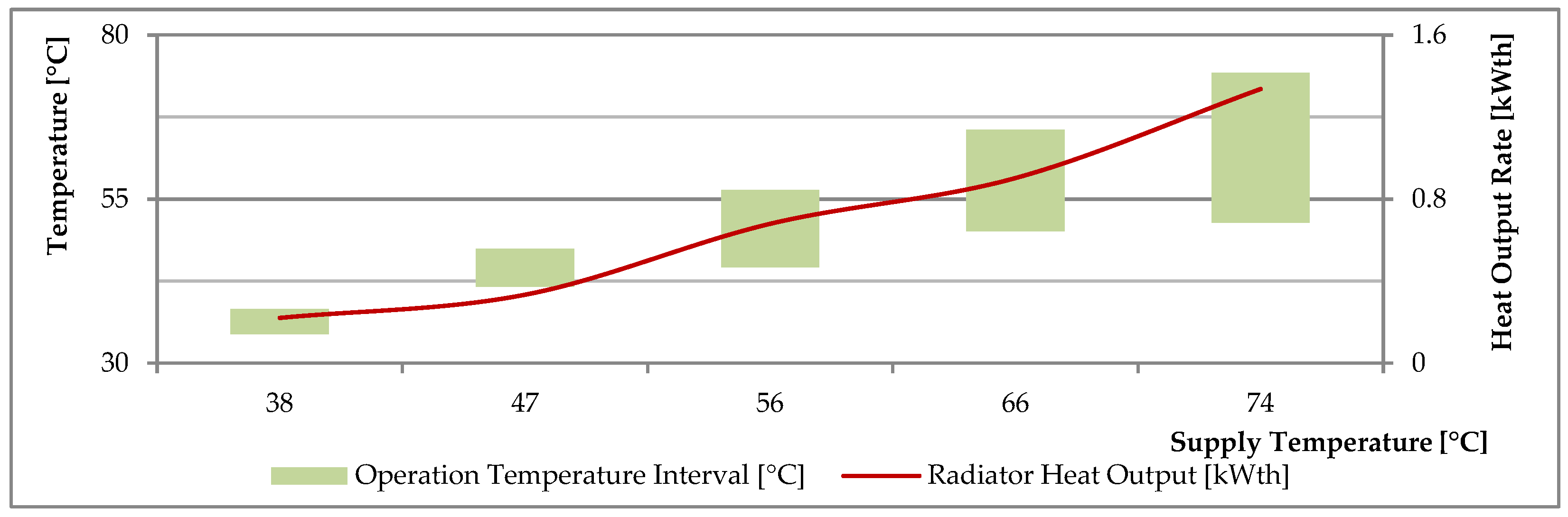
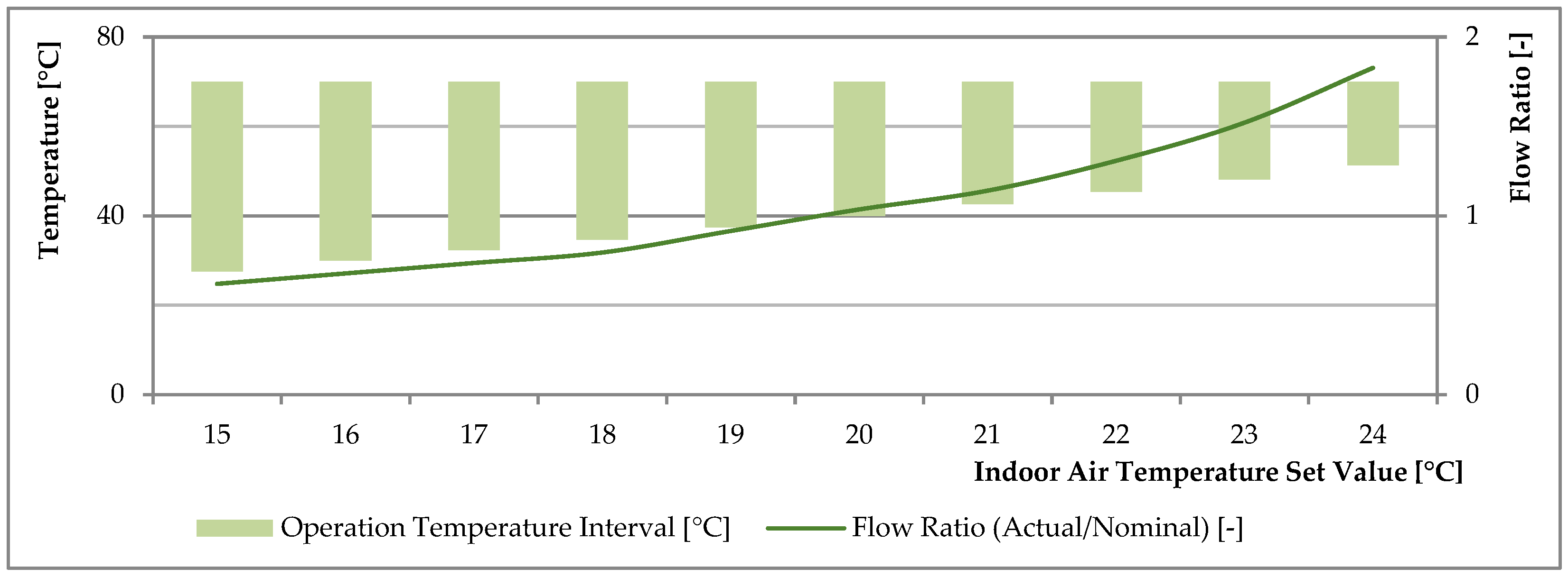
Operation Parameters

The thermo-hydraulic operation parameters, particularly supply temperature and flow rate, significantly influence radiator heat output, independent of other equipment (e.g., heat exchangers, thermostatic radiator valves). It is important to emphasize that for a given radiator unit, varying temperature schemes (supply and return temperatures) require adjustments in the water mass flow rate to maintain optimal heat output [26,71].
Calisir et al. [40] present the effect of the supply temperature on the radiator heat output for various inlet-outlet connection positions at various rates of mass flow. The results show a significant influence by the supply temperature with increasing degrees leading to advanced heat output rates with enhanced supply–return temperature difference, as shown in Figure 7.
Changing operating conditions often require adjustments to maintain the desired heat demand, which is closely linked to control mechanisms such as thermostatic radiator valves. To prevent overheating, the supply temperature, flow rate, or both must be reduced. Conversely, to address underheating, the supply temperature or flow rate, or both, should be increased. A lower supply temperature necessitates a higher flow rate adjustment, while a higher supply temperature requires a lower flow rate adjustment, similar to the function of thermostatic radiator valves [30,72,73,74].
Figure 8 illustrates the radiator’s operation with a thermostatic radiator valve. Unlike Figure 7, each temperature interval on the supply temperature axis (x-axis) delivers a consistent heat demand. The thermostatic valve adjusts the flow rate based on the supply temperature to meet this demand. As the supply temperature increases and the return temperature decreases, a lower flow rate can still satisfy the same heat demand. This relationship is supported by the inverse proportionality between the supply–return temperature difference and the flow rate [75].
It should be remarked here that a higher degree at the supply temperature, either at constant-flow (Figure 7) or at variable-flow operation (Figure 8), leads to a lower degree at the return temperature by the heat emitter unit, as stressed by most articles [1,23,28,40,48,76].
Increasing the supply temperature during peak hours can reduce flow rates and lower return temperatures significantly with variable-flow operation. Consequently, lower flow rates year-round can reduce pumping costs and enhance DH capacity. By raising supply temperatures sufficiently during peak periods to match the flow rates of low-load periods, similar flow rates can be achieved [23,26]. However, it is important to note that higher supply temperatures may impact DH efficiency due to increased heat loss and generation performance [76].
Calisir et al. [40] examined the effect of mass flow rates on radiator heat output, finding that variations within the range of 0.01–0.014 kg/s and 0.022 kg/s had minimal impact on heat output, although higher flow rates generally increased it. Langendries [8] noted that variable flow control significantly reduces return temperature under low flow-rate conditions, defined as less than half the nominal flow rate. However, this must be distinguished from findings [53,54] both using data partially from Schlapmann [77] (see Figure 9), which indicate that low flow rates can reduce radiator heat output and, depending on the inlet-outlet connection, lead to higher return temperatures and potentially uncomfortable heating conditions [53].
Most commonly, due to its simplicity, the actual heat output of a radiator at any condition is calculated by means of the logarithmic mean temperature difference (LMTD) method, its expression given in Equation (1) [25,54].
q ˙ = q ˙ o × L M T D / L M T D o n
where q ˙ refers to a heat output [Wth], the subscript o indicates the original design condition and the superscript n is the dimensionless coefficient, its value being 1.3 for radiators.
Considering the experimental observations by Schlapmann [77], the modified AMTD method is proposed with the correction factors considering the flow rate and the connection type, details shown in Figure 7, its expression given in Equation (2).
q ˙ = q ˙ o · · A M T D / A M T D o n · φ
The same degradation of the heat output with low flow rates is shown by Jian et al. [38], as obtained for three different radiator types that are a cast-iron radiator, a steel radiator and a copper-aluminium radiator; and by Petitjean [78]. Another observation is indicated by the lessened effect of the flow rate on the heat output and the indoor temperature increase when the flow rates are excessive (e.g., 150% relative to the nominal flow rate), as also stated by CIBSE guide report [32].
The Schlapmann correction factors are derived for flow rates above 20% of the nominal flow rate. At ultra-low flow conditions (rate ratios lower than 20% of the nominal) the supply water medium after entering into the radiator (chamber) loses its temperature quickly due to a mixture occurring in the inlet region with the locally cooled radiator water there. By that, the inlet temperature becomes lower than the supply temperature and, as shown in Figure 9, low radiator inlet temperatures result in lower radiator performance with diminished heat output, poor cooling (low ∆T), and reduced return temperature. For such extreme low flow conditions Bach’s equation can be used, the details about this equation are given in [27,54].
Tunzi et al. [71], as part of a PhD thesis [79], demonstrate how radiator operation parameters impact performance in old Danish buildings (i.e., ‘House 3’). The study focuses on applying low-temperature DH to existing buildings without insulating renovations, adjusting only the supply temperature. Two optimization strategies were employed: (i) minimizing return temperature at a fixed supply temperature and minimizing supply temperature while ensuring a return temperature of at least 25 °C, and (ii) minimizing both supply and return temperatures within a supply temperature range of 50 to 80 °C. The first optimization yielded a supply temperature curve from 80 °C at 5 °C outdoor temperature, declining to 50 °C at 13 °C and remaining at 50 °C in warmer periods. The second optimization resulted in a maximum supply temperature of 70 °C at −10 °C, decreasing to 50 °C at 10 °C, and maintaining 50 °C in warmer periods. Return temperatures ranged from 32 °C to 20 °C for the first optimization and from 38 °C to 20 °C for the second.

2.2.2. Forced Convection Room Heating Units

Forced convection room heating units, including air handling units and fan coil units, are notably sensitive to water flow rates, requiring meticulous control of supply and return temperatures. Accurate adjustment of the water flow rate and appropriate valve selection are crucial, as improper flow can significantly affect heat transfer efficiency. Unlike radiator units, where flow adjustments are less critical, air handling units demand precise valve authority, even at partial loads, to avoid reduced heat transfer efficiency due to low flow rates [12,31]. Langendries [8] highlights that variable flow control offers advantages over constant flow in hydronic systems for air handling units, similar to radiator systems. However, for controlling airflow and handling variations in inlet air temperatures, a constant flow strategy is recommended, even for systems recirculating indoor air.

2.2.3. Floor Heating

Floor heating is advantageous for achieving low return temperatures due to its extensive heat transfer area, which maximizes heat emission to the indoor air under both nominal and partial load conditions [8,31,32]. However, floor heating systems are primarily known for their ability to operate at low supply temperatures rather than achieving low return temperatures [31,80]. This limitation arises from the need to avoid high surface temperatures that could cause scalding and to maintain a uniform temperature gradient across the floor for comfort. To address these issues, pipe layout designs, such as counter-flow arrangements, and high-flow operations are used to ensure a minimal temperature difference between inlet and outlet regions [31]. Additionally, supply temperatures significantly affect both surface and indoor air temperatures [81]. For example, a supply temperature of 30 °C results in a 3 °C inlet-outlet temperature difference, maintaining uniform surface temperatures [80,82]. Ovchinnikov et al. [35] report typical operation temperature ranges for floor heating at 35/25 °C, compared to 45/25–35 °C for ventilation radiators and 55/35–40 °C for low-temperature radiators. Floor heating systems, known for their thermal mass, respond more slowly to heat gains, which can lead to higher return temperatures compared to quicker responding units that adjust to lower heat loads [24,83]. The depth of the floor heating pipes also impacts thermal mass, with shallow piping leading to faster indoor air heating [81].

2.2.4. Panel Heating

Panel heating units, similar to floor heating systems, benefit from large heat transfer surfaces but differ in thermal mass. Panel radiators have a lower mass and less water medium, resulting in quicker response times compared to floor heating systems. Karabay et al. [84] found that wall panel heating units provide greater thermal performance and comfort than floor heating systems. For a comprehensive review of radiant heating systems, see [85,86].
Chen [87] compared ceiling panels with radiators, noting that ceiling panels consumed 17% more heat due to their substantial thermal mass. Additionally, both ceiling panels and radiators suffer from excessive heat loss through the back-wall.

2.3. Thermostatic Radiator Valve

Thermostatic radiator valves, commonly known as TRVs, are self-regulating devices that either operate autonomously or via a remote controller, such as programmable thermostats. Their ability to continuously measure indoor temperature and adjust to varying heat demands significantly impacts the return temperature [8,12,14,88,89]. Thermostatic radiator valves regulate the flow based on the temperature difference between the actual and perceived indoor temperatures, thereby aligning heat output with demand efficiently. Lower heat loads generally lead to lower return temperatures compared to higher loads. Thermostatic radiator valves are particularly effective during low-load periods, as they can throttle the flow to achieve minimal return temperatures [89,90]. However, faulty or improperly set thermostatic radiator valves can lead to increased return temperatures and overheating [12,39].
Based on the dynamic simulation conducted by Xu et al. [91], it was found that setting thermostatic radiator valves to a pre-setting rate between 2–3 significantly reduces overheating degree-hours from 2833 °C·h (in the absence of thermostatic radiator valves) to 50.1 °C·h. This adjustment also results in a 12.4% reduction in overall yearly heat consumption. Similarly, Monetti et al. [92] report a reduction ratio of 10% for the same parameter. Xu et al. [93] compared various reference cases (without thermostatic radiator valves) based on scenarios with high flow rates, large radiator surfaces, and elevated supply temperatures. Their findings demonstrate that using thermostatic radiator valves, set at a rate of 2–3, significantly reduces overheating degree-hours across all scenarios. Notably, the overheating degree-hours were higher in the reference scenarios compared to the nominal operation state without the additional sizes specified [93].

2.3.1. Performance

Thermostatic radiator valves play a crucial role in adapting heating systems to varying heat demands, making their performance vital for reducing return temperatures in DH systems. The efficiency of thermostatic radiator valves in regulating heat output directly impacts the overall effectiveness of heat transfer and the thermal dynamics of the system.
Energy labelling, as detailed in Appendix B, offers essential insights into the performance characteristics of thermostatic radiator valves. This labelling is instrumental in optimizing heating efficiency by providing information on the efficiency of thermostatic radiator valves in managing heat output and controlling return temperatures.
When considering low-flow heating systems, it is important to account for the minimal controlled flow that a thermostatic radiator valve can maintain. This is represented by rangeability, the ratio of nominal flow to the minimum flow the valve can sustain [94,95]. Brand et al. [37] note that achieving flow rates below the valve’s minimum can result in uncontrolled on-off operation, potentially causing overheating due to delayed valve response. They recommend adjusting the supply temperature to maintain a flow rate within the valve’s operational range [37].
As an alternative to classic “flow control” (or “floating control”) thermostatic radiator valves, “on-off control” thermostatic valves merit consideration [47,96]. Li et al. [96] investigate the impact of on-off control on return temperature. The principle is to adjust on times to ensure the indoor heat emitter provides sufficient heat. However, prolonged on times result in slow cooling of DH water, raising the return temperature. They propose adaptive control to modify on-off times based on indoor and return temperatures. Overshoot lengthens the cycle period, while undershoot shortens it. A control measure to achieve a low return temperature without too brief cycling is also suggested. Measurements over seven days in April in identical apartments show that thermal comfort can be maintained with on-off periods of 2 to 8 min, while outdoor temperatures ranged from 10 °C to 20 °C during the day and 5 °C to 15 °C at night. With a supply temperature of 45 °C, return temperatures were recorded as follows [96]:
  • In the first apartment, set at 25 °C, the return temperature varied between 26.6 °C and 28 °C, peaking briefly at 29 °C.
  • In the second apartment, set at 26 °C, the return temperature ranged from 28 °C to 31 °C, peaking briefly at 32 °C.

2.3.2. Temperature Set-Back

Occupants often lower the indoor set temperature during less-populated hours or in less-used rooms. Modern programmable thermostats offer greater flexibility than older systems with manually adjusted thermostatic radiator valves, allowing for multi-room (or ‘multi-zone’) control and user-defined time scheduling (on, off, and/or set-back) for each room [24,97,98,99]. Set-back, whether zone-based or time-based, reduces heat demand and thereby lowers the return temperature.
Brand et al. [37] demonstrate the impact of set-point temperature on return temperature. When the indoor set temperature is 20 °C, a radiator designed for a 55/25/20 °C temperature scheme achieves an average return temperature of 25 °C. Increasing the set temperature to 22 °C raises the average return temperature to 26 °C [37].
Badiei et al. [97] illustrate the savings potential for various resetting procedures for a reference building with an annual gas usage of 14,615 kWhth. Reducing the indoor temperature set point by 1 °C to 5 °C across all rooms results in annual gas savings of 16% to 64% (with a 5 °C reduction being impractical due to comfort loss). Additionally, decreasing daily heating duration from one to five hours yields savings of 5.8% to 27.9% annually. These simulations are based on a two-storey house with a heated area of 79 m2 from the 1940s, using weather data for Birmingham, UK [97].
Danes et al. [47] illustrate the effects of varying set degrees on thermostatic radiator valves for a radiator operating at a 70/40/20 °C supply/return/indoor temperature scheme (Figure 10). They show that, with constant heat load and supply temperature, a lower set degree reduces the mass flow rate and increases the supply–return temperature difference, while a higher set degree leads to diminished performance [47].
Beizaee [99] reports an 11.8% reduction in annual gas usage by using programmable thermostats instead of pre-setting thermostatic radiator valves, based on an eight-week study of a semi-detached house in the UK from the 1930s. The study shows consistent indoor temperatures during occupancy, with a 1.8 °C setback in bedrooms during sleeping hours. Savings are greater during weekdays with intermittent heating compared to weekends, and a non-insulated house with zone control saves more energy than a newly constructed house with continuous heating [99].
Lauenburg [100], as cited by Frederiksen and Werner [101], identifies potential issues with the night set-back practice. First, the savings achieved from night set-back are considered negligible when accounting for the heat stored in the building’s thermal mass. Second, the need for additional morning heating to return to the typical set temperature can lead to significantly higher flow rates and return temperatures during the morning warm-up period.
Frederiksen and Wollerstrand [75] suggest two solutions to address this morning warm-up issue: (i) increasing the supply temperature to the building heating system to a higher level, and (ii) employing adaptive control to optimize both the warm-up time and supply temperature simultaneously.

2.3.3. User Awareness and Behaviour

Improper use of thermostatic radiator valve settings by heat consumers can lead to inefficiencies. A survey in the UK revealed that 32% of dwellings had thermostatic valves set to their maximum, while 65% were set higher than necessary [102].
To mitigate issues arising from incorrect valve settings, Gudmundsson et al. [103] suggest installing a return temperature limiter at the radiator outlet. This component, used alongside the thermostatic radiator valve, ensures that return temperatures are maintained at a minimum level. The return temperature limiter functions by monitoring the return water temperature and reducing radiator flow if the (return) temperature is too high [104]. This device is recommended for safety, especially if the thermostatic radiator valve malfunctions, to maintain thermal comfort in response to varying heat demands [105].
Programmable thermostats face user awareness issues due to the complexity of their control panels. A survey of students and researchers found that users struggle with the control interface, which features numerous small buttons and unclear terms. While the panel offers many functions, users typically only utilize basic features like temperature adjustment and airflow direction. Advanced features, such as temperature limits and programmable settings, remain underused, leading to missed energy savings [106]. Further details on user awareness of thermostatic valve characteristics are available in [107].
Smart control systems, increasingly popular alongside programmable thermostats, offer automated heating schedules based on occupancy rather than manual presets. Key features include (i) occupancy sensors that activate heating when people are present and deactivate it when they leave, (ii) predictive activation of heating before residents return, (iii) occupancy detection based on electrical usage, and (iv) learning from historical occupancy data. These systems enhance energy efficiency by reducing heating during unoccupied periods and ensuring comfort through predictive control, considering the building’s thermal mass [108,109].

2.3.4. Faults

Liao et al. [102] found that 65% of evaluated thermostatic radiator valves were unable to reduce radiator heat output, resulting in overheating. Danes et al. [47] attribute this to sensor malfunctions, which can arise from local temperature influences or direct sunlight. Additionally, valve rigidity, due to prolonged inactivity or sustained settings, can also cause operational issues [110] (personal communication with Dirk Vanhoudt during an internal meeting on 10 May 2017).
Henze and Floss [111] outline the effects of thermostatic radiator valve design on the weighted return temperature:
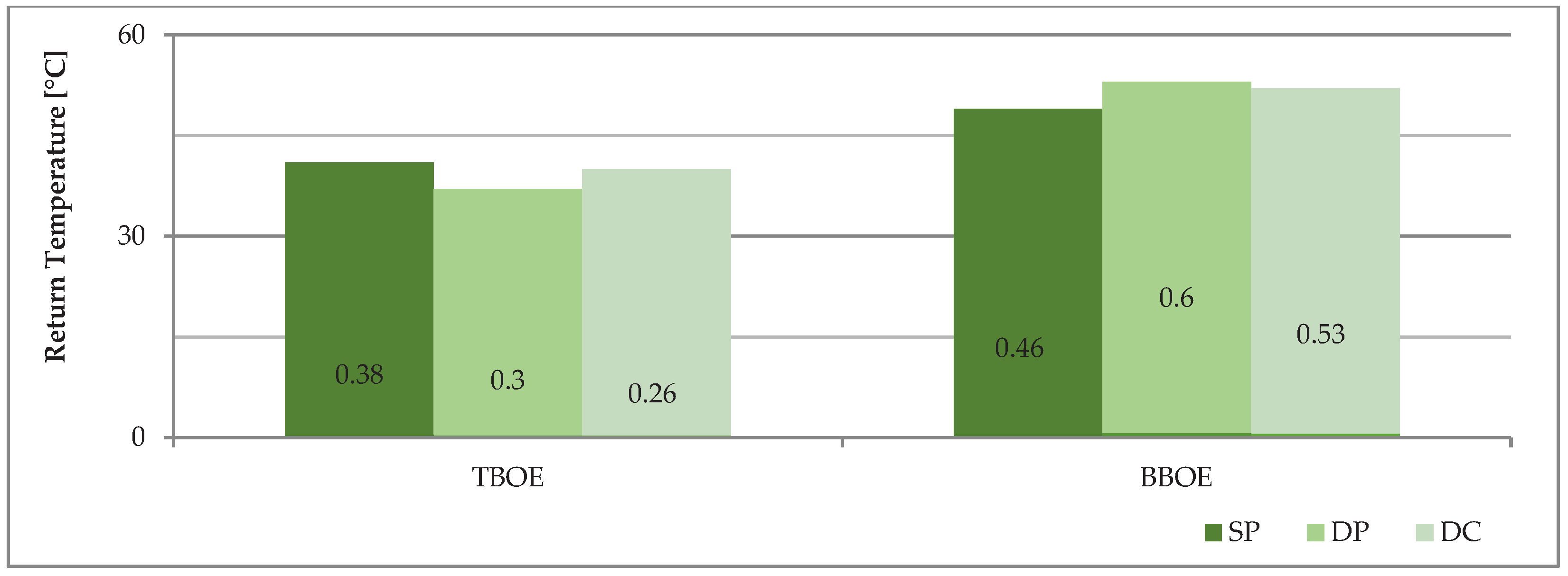
  • An oversized valve (with an equal percentage characteristic) increases the average return temperature by 0.6 °C, assuming proper hydraulic balancing.
  • With hydraulic imbalance, the return-temperature increase is 1 °C.
  • A valve with a linear characteristic causes a return-temperature increase of 2.5 to 4 °C compared to one with an equal percentage characteristic, depending on hydraulic balancing.
  • An oversized linear characteristic valve, combined with hydraulic imbalance, results in a 2 °C return-temperature increase, totalling 6 °C when accounting for controller gain.

2.4. Substation

Substations (also known as ‘heat interface units’ or ‘flat stations’) serve as crucial connections between a building’s heating system and the DH network. These units integrate various components, such as heat exchangers, valves, and sensors, to control and ensure safe heat transfer in alignment with both building requirements and DH network conditions [14,112,113].
This section addresses challenges related to return-temperature reduction in building substations. It focuses on substation performance, types, and control strategies, as well as domestic hot water issues and potential faults. Given the widespread use of substations in DH systems, their performance is critical to overall system efficiency.

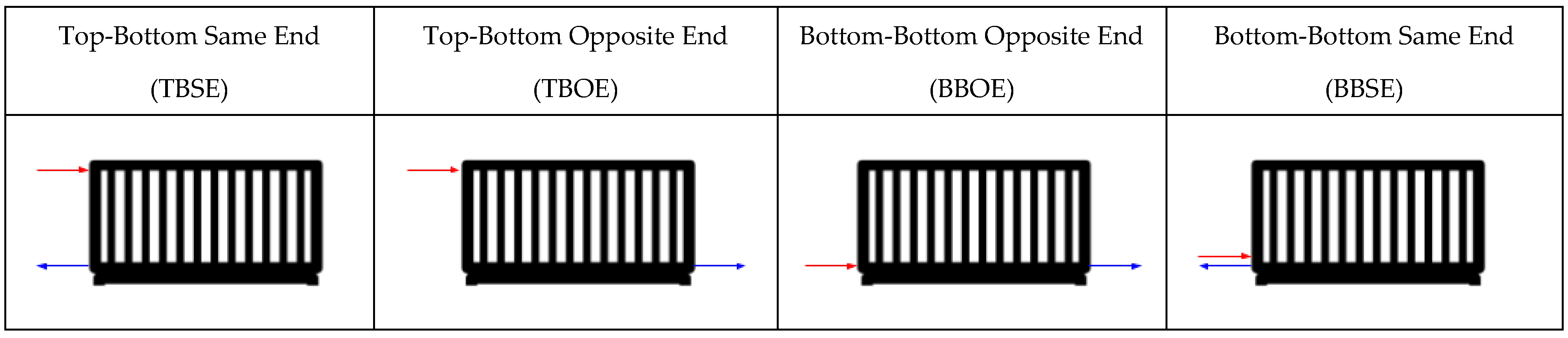
2.4.1. Hydraulic Interface

The configuration of sub-components in a substation significantly impacts its performance and the resulting return temperature [34]. Building substations address two primary demands: the connection for space heating and the domestic hot water service, based on standard practices.
Typical substation types connect the supply to the space heating service pipeline either directly or indirectly. An indirect connection uses a heat exchanger to separate the DH network from the indoor loop, while a direct connection circulates the DH heat carrier medium directly within the indoor loop [13,100,112,114]. Each connection type has advantages over the others to varying degrees, but this is outside the purview of this review study (a comprehensive list can be found on page 53 of [13]).
Direct connections offer specific benefits for return-temperature management [13]:
  • The return temperature on the primary side of the heat exchanger is typically higher than on the secondary side due to the ‘temperature approach’ phenomenon. This can be mitigated by using cross-flow plate heat exchangers or by oversizing the heat exchangers to allow more cooling on both sides [76]. Direct connections reduce this temperature loss and lower the DH operation temperature. In Danish DH systems, direct connections are increasingly preferred for their effectiveness and simplicity [14].
  • Faulty substations often lead to excessive return temperatures. Direct connections, with their simpler design and fewer components, are less prone to faults and do not suffer from issues like fouling at heat exchangers [14,115]. Fouling has been reported as 0.048 K/kWth for space heating plate heat exchangers in Belgrade, Serbia [116].
  • Trüschel [12] states that factors affecting return temperature include changes in the indoor heating system flow and increased primary DH flow due to reduced heat transfer in heat exchangers. These factors can result in higher return temperatures at the DH side (see Section 6.7 of this reference [12]).
Domestic hot water units in substations can be categorized as follows [13,100,114]:
  • Instantaneous heat exchanger: Provides hot water on demand through a dedicated heat exchanger.
  • Heat storage tank: Utilizes a smaller heat exchanger and a storage tank that charges during off-peak times.
The advantages and disadvantages of these options are detailed in [13]. Notably, substations with storage tanks often avoid the need for thermostatic bypasses, which can be beneficial for managing return temperatures [7,8,13,117].
Configurations using only heat exchangers provide domestic hot water instantly at lower return temperatures. Key factors affecting DH water cooling include the heat exchanger size and flow configuration, with “counter-flow” being more effective than “parallel-flow” [118]. Zinko et al. [10] note that return temperatures at the DH side of the heat exchanger decrease with increased domestic hot water demand, attributed to the cold municipal water at 12 °C. Field data from the Lystrup low-temperature DH system during summer show return temperatures of 29 °C for a substation with storage and 26 °C for one with an instantaneous heat exchanger [119].

2.4.2. Substation Performance

The overall performance of a substation is determined by the space heating interface, domestic hot water units, and keep-warm components/controls [14,120]. Effective substation operation requires proper design, commissioning, and management of the indoor heating system to ensure the health of the DH system [121,122].
Significant efforts in the UK focus on evaluating substation performance to advance DH, aligning with long-term national objectives. The UK has developed a test procedure based on the Swedish certification standard (F:103-7e by Svensk Fjärrvärme AB, Stockholm, Sweden) but tailored to local conditions [123]. This protocol aims to [121] do the following:
  • Establish performance metrics for UK substations.
  • Identify underperforming units and provide performance benchmarks.
  • Offer a testing framework for manufacturers to adapt products to UK conditions.
  • Assess the impact of factors such as temperature settings on substation performance.
In Sweden, substation certification requires adherence to technical regulation F:103-7e. This process involves a detailed test report on components and performance, followed by inspections from the SP Technical Research Institute of Sweden [123]. The ‘Volume Weighted Return Temperature (VWART)’ metric, which evaluates performance across space heating, domestic hot water, and keep-warm services, represents substation efficiency over the heating season and year-round. Test results for various substation types are available on BESA [124] and FairHeat [125] websites, with similar certification procedures likely managed by Euroheat & Power [126].
Properly functioning older substations can achieve low return temperatures comparable to modern systems, although domestic hot water units may exhibit slightly higher return temperatures. This performance is attributed to significant supply–return temperature differences and low operating temperature levels in both historical and current design practices [127] referring from [128,129,130].
When assessing substation performance, the heat exchanger’s effectiveness is crucial. The ‘thermal length’—the ability of the channel (primary DH side or secondary building side) to achieve temperature changes based on the logarithmic mean temperature difference—reflects the heat exchanger’s performance. This metric is influenced by the physical characteristics of the channel (e.g., plate length, surface pattern) and operational factors (see Figure 11) [131,132,133].
It is obvious to state that a heat exchanger with a longer thermal length is required to achieve a larger supply–return-temperature differential [80,120,133]. Thorsen et al. [120] recommend enhancing the heat transfer area and thermal length of substation heat exchangers for future low-temperature operations, noting that the marginal cost of increasing the heat transfer area is minimal. They suggest increasing the heat transfer area and thermal length by factors of 3 and 2.5, respectively, for space heating exchangers, and by a factor of 2 for domestic hot water exchangers. Averfalk and Werner [80] advocate for expanding the thermal length from the 2 used in the 1960s to 4 currently, with an additional factor of 1.5–2 for future low-temperature DH systems, resulting in a thermal length of 6–8.

2.4.3. Substation Control

The performance of a heat exchanger is influenced by operational characteristics on both the primary and secondary sides. Trüschel [12] notes that an increase in the secondary return temperature leads to a rise in the primary DH side temperature, despite the primary side degree being lower than the secondary degree. This effect is exacerbated by increased flow on the building side. At low flow rates, the return temperature on the DH side increases further [12]. Additionally, efficiency decreases under low heat load conditions [22] as cited from [134]. Parsloe [31] recommends using variable flow control with a variable temperature scheme to achieve a significant supply–return temperature difference, compared to a constant flow control strategy.
A control strategy for indirect connections at the substation level, utilizing variable flow control, aims to achieve a low return temperature on the DH side of the heat exchanger. The impact of reducing the return temperature from the indoor heating system on the DH side varies based on the heat exchanger performance and heat demand rate [42,48]. Performance analysis shows that initially lowering the secondary building side flow rate decreases the primary DH side return temperature, but further reductions eventually increase it. Łukawski’s diagrams (Figure 5.3 in this reference) [135] illustrate the variation in primary DH return temperature with secondary side flow rates for both 80/60 °C and 55/45 °C operation temperature schemes (see Figure 5 of reference [48]).
The ‘adaptive substation control’ strategy for indirect connections optimizes operation by adjusting the flow rate and supply temperature in the indoor heating system to minimize the return temperature at the DH side of the heat exchanger. This approach considers the DH supply temperature and heat load variations [42,43,75,76,122], with algorithm details provided in [43] (see Figure 12). The strategy accounts for the thermal response of the indoor heating unit and heat exchanger performance, varying by location and operation temperature [48,136].
In the Fridhem, Sweden study, adaptive substation control reduced the weighted annual return temperature by 2.5 °C and the flow rate by 4%. The experiment was conducted on 1960 residences using an 80/60 °C temperature scheme, with peak heat demand at 185 kWth and a demand of 40 kWth at 0 °C outside [43].
The impact of the indoor heating system flow rate on the DH side return temperature is variable and depends on the heat load. Specifically, the effect becomes more significant under low heat load conditions. Conversely, the size of the heat exchanger influences the intensity of this effect in high heat load scenarios. Larger heat exchangers tend to have a more pronounced impact, facilitating a greater supply–return temperature difference. In contrast, nominally sized heat exchangers exhibit a reduced effect [75,76].
Figure 13, based on Ljunggren and Wollerstrand [42], shows the reduction in DH side return temperature resulting from various combinations of oversized radiators, heat exchanger sizes, and flow control strategies (constant flow with supply temperature adjustment or adaptive substation control). Similar data on the effects of over-sizing radiators and heat exchangers for different temperature schemes (55/45 °C, 60/40 °C, and 80/32 °C) are presented in [76].
Frederiksen [138] reports that an increase in heat exchanger size raises the ideal secondary supply temperature under adaptive substation control. The study details the variations in primary DH side return temperature for different heat exchanger sizes, comparing constant flow and adaptive flow strategies. Optimization via adaptive control achieves a 2–3 times greater reduction in primary DH side return temperature compared to constant flow strategies [138].
Gustafsson et al. [139] propose a new control strategy for indirect substations using a constant-speed pump, avoiding weather correction at the substation level. Instead, the radiator inlet temperature is based on the DH supply temperature. Experimental results show that this approach maintains thermal comfort while achieving equal or improved DH water cooling [139].

2.4.4. Temperature Maintenance

This section addresses the keep-warm requirements for domestic hot water in multi-storey building substations, which are larger than those for single-family units. These substations centrally produce domestic hot water for distribution to individual flats via separate circuits from space heating pipelines. To ensure that hot water is delivered quickly and to prevent bacterial growth, such as legionella, continuous temperature maintenance is essential. Alternative methods for lowering minimum temperature requirements, beyond thermal treatment for legionella, are detailed in [140].
According to Danish Standard DS439 [141], the waiting period for hot water delivery must be at least 10 s, with 30 s as the absolute maximum [142]. Temperature maintenance can be achieved through various methods [34,142,143,144,145,146,147]:
  • Continuous recirculation of hot water from the building circuit back to the substation via a dedicated pipeline, adjusted to compensate for heat loss.
  • Electric heat tracing in the domestic hot water circuit, eliminating the need for a recirculation line.
  • Installation of in-line water heaters near hot water faucets.
  • Designing multi-storey substations with local in-building networks, allowing each apartment to have its own flat substation for space heating and hot water, with thermostatic bypasses required to prevent cooling of the heat carrier medium.
Bøhm [143] emphasizes that in an experimental study of Danish buildings from 1906 to 1996, heat loss from domestic hot water storage and circulation accounted for 65% of total consumption. The heat loss from circulation varied from 23% to 70% in residential buildings and 54% to 89% in office buildings, attributed to low demand during continuous recirculation. The study noted that recirculated water temperatures ranged from 19 °C to 45 °C in homes and 11 °C to 24 °C in offices, often leading to significant cooling of DH water. Recommendations include shortening circulation lines, optimizing tap quantity and location, and improving insulation or using twin or co-axial pipes to reduce heat loss, with potential savings of up to 40% [143,148].
Electric heat tracing, an alternative to recirculation lines, heats the domestic hot water supply pipeline to offset heat loss. However, this method is less efficient compared to recirculation systems due to higher electricity consumption, as noted by Bøhm [143] and Yang et al. [145]. Electric heat tracing results in lower return temperatures at the DH side, but smart controllers can reduce electricity use by 20% [145]. Alternatively, Yang et al. [146] propose using a heat pump with in-line coaxial pipes embedded in the supply pipe to maintain a DH return temperature of 25 °C. This approach, which avoids the need for thermostatic bypasses at flat stations, is more cost-effective compared to other temperature maintenance options.
Yang et al. [144] compare several temperature maintenance options for multi-storey buildings and focus was given to return temperature levels:
  • With a recirculation pipeline and a storage tank, the building substation return temperature is 28 °C with a supply temperature of 65 °C.
  • For a system where each flat station produces domestic hot water locally and includes thermostatic bypasses, the return temperature is 24 °C with a supply temperature of 65 °C.
  • Using a heat pump without storage and a recirculation pipeline, the return temperature is 20 °C with a supply temperature of 50 °C.
  • When supplying heat to flat stations with comfort bathrooms instead of thermostatic bypasses, the return temperature is 23 °C with a supply temperature of 50 °C.
  • Central domestic hot water production with electric heat tracing systems yields a return temperature of 19 °C.
  • For flat stations with micro storage tanks and booster heaters, the return temperature is 16 °C.

2.4.5. Substation Faults

Faults in the substation, indoor heating systems, or domestic hot water units often lead to elevated return temperatures in the DH system. Causes of these malfunctions include design errors, incorrect commissioning, and equipment breakdowns [10,12,119]. Zinko et al. [10] found that one-third of these faults caused thermal comfort issues, while the remaining two-thirds were the main causes of the inadequate cooling at the substations.
Christiansen et al. [119] analysed the Lystrup low-temperature DH system, serving low-energy homes, and reported the following observations:
  • A malfunctioning substation resulted in a summer average return temperature of 43.6 °C, compared to 29 °C for the best-performing substation with a storage tank.
  • Two malfunctioning substations, affected by excessive flow due to a faulty control valve, recorded a summer average return temperature of 40.3 °C. In contrast, the best-performing substation, which used an instantaneous heat exchanger without a storage tank, achieved a return temperature of 26 °C.
Zinko et al. [10] reported that an accidentally opened by-pass valve in a shopping centre (during commissioning in 1972) was obtained to cause an increase in the supply–return temperature difference by 30 °C. This issue was resolved by simply closing the valve.
Following building renovations or replacements of heating system components, issues may arise from the incorrect operation of the substation or other components.
Lauenburg and Wollerstrand [43] indicate that the minimum pump speed range of 30% to 100% often prevents pumps from achieving the low flows required after implementing adaptive substation control. Failure to maintain these low flows can lead to increased return temperatures. Solutions include excessive throttling of the valve post-pump or adjusting the pump frequency converter to a range of 2% to 100% [43].
Werner [149] categorizes typical substation faults into four main types (additional common fault types are listed in [10,150]):
  • Design errors include issues such as oversized valves, inadequate heat exchanger designs with short thermal lengths, and using parallel flow configurations in heat exchangers rather than the preferred counter-flow arrangements.
  • Malfunction errors refer to problems like excessive fouling in heat exchangers beyond normal levels and failures in control units, valve motors, or measurement sensors.
  • Set-point errors involve incorrect settings, such as high set-points in household hot water heaters and indoor heating systems.
  • Operational errors pertain to issues with domestic hot water units and indoor heating systems that reduce overall substation performance.
Trüschel [12] emphasizes that return temperature sensitivity is greater in low-flow systems compared to high-flow designs. Excessive opening of the balance valve in low-flow systems leads to insufficient cooling of the heat carrier water and high return temperatures. Conversely, overly closing the valve results in inadequate heating. High-flow systems exhibit similar issues but require larger deviations in valve settings to achieve comparable effects.
Frederiksen et al. [118] highlight that inadequate domestic hot water control units can adversely affect return temperatures. Their study shows that a slow response from the control unit can cause unexpected extra-flow at the DH side of the heat exchanger after tapping closes, leading to excessive return temperatures due to circulation hold. Current efforts aim to improve heat exchanger control by enhancing set value tracking, reducing overshooting, and decreasing settling times [151].
Effective “substation fault detection and diagnosis” is essential for maintaining low return temperatures in DH systems. Estimating the optimal return temperature is challenging due to the diversity in building types, insulation, indoor heating systems, and substation configurations serviced by existing DH systems. Additionally, atypical end-users like industries or greenhouses introduce irregular heat load patterns. Therefore, fault diagnosis at the substation level is crucial for understanding DH system performance. Diagnostic practices, using measurements to identify deviations from ideal return temperatures, are necessary for verifying the operation of space heating and domestic hot water units during summer and winter [10,33,127,150].
The IEA report [10] outlines three diagnostic approaches: ‘excess-flow’, ‘target return temperature’, and ‘individual substation analysis’:
  • The excess-flow method involves measuring flow rates at each substation to identify deviations from a target return temperature. Substations are ranked based on excess flow levels, with those at the lower end of the list recommended for further investigation into high return temperatures.
  • The target return temperature approach sets a benchmark return temperature for a DH network. Statistical analysis of return temperature data from comparable substations determines the benchmark. If establishing a reference value is problematic, thermodynamic modelling is suggested. Detailed descriptions of these methods are provided for the Cheongju and Skogas DH systems in Section 4 of the IEA study [10], with additional insights available in references [1,127,150,152].
Parsloe [31] recommends continuous post-commissioning monitoring of substations to detect deviations in the supply–return temperature difference, which may indicate component malfunctions requiring repair. Similarly, Gadd and Werner [127] advocate for a “temperature difference signature” approach, utilizing data from heat meters, including supply and return temperatures and flow rates, to identify issues.

2.4.6. Substation Cascading

In DH systems, cascading involves the sequential use of heat across multiple units (or subbranches), where each unit utilizes thermal energy from the return medium of the preceding one when available. Based on examples from the former Soviet Union and Sweden, Frederiksen et al. [1,118,153] illustrate various cascading configurations, including the following:
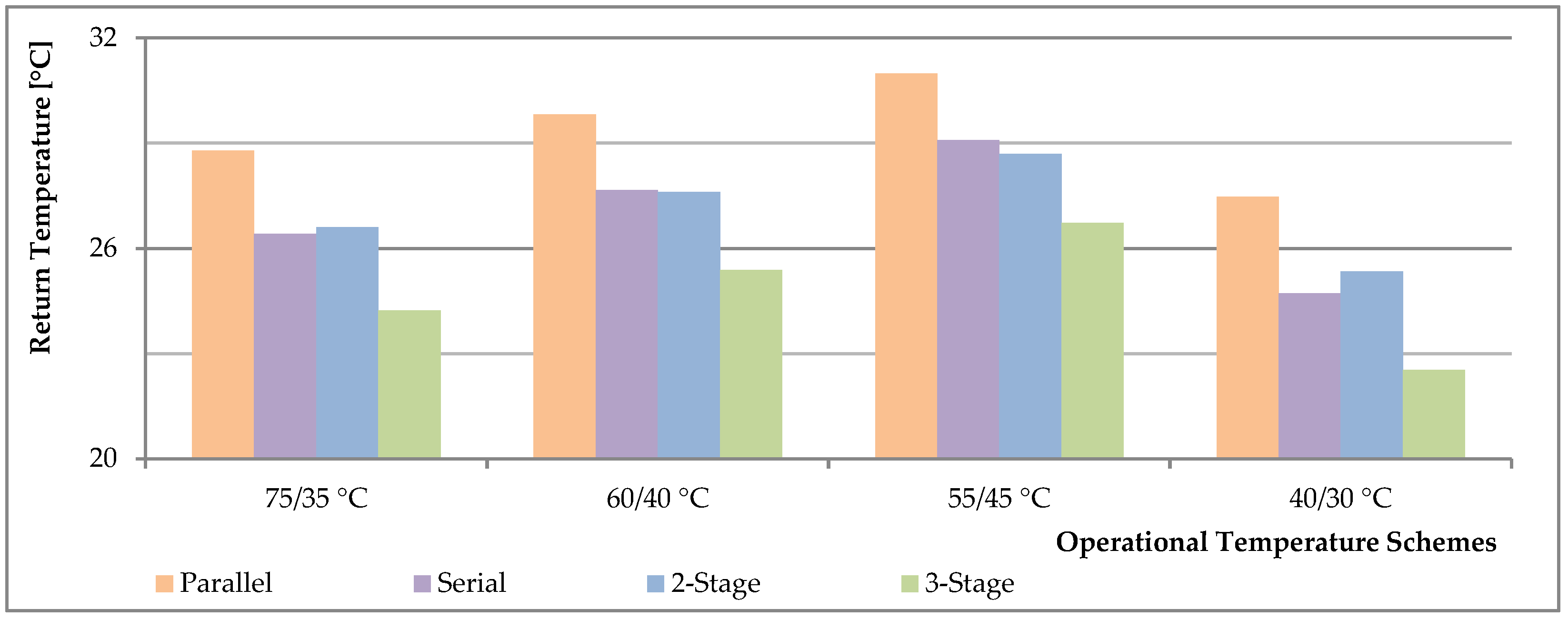
  • Serial connection: Two interface units are connected in series, with configurations including domestic hot water on top (the space heating unit is positioned after the domestic hot water unit) and space heating on top (the arrangement is reversed).
  • 2-stage connection: This setup directs the return medium from both units to an additional heat exchanger that pre-heats the tap water before final heating.
  • 3-stage connection: This configuration adds a pre-heating unit in series (domestic hot water unit, space heating unit, and pre-heater). The Swedish version includes a mixing bypass for the domestic hot water circuit, while the Russian version features a bypass line to direct DH supply water to the space-heating circuit when needed.
The IEA report [136] proposes an alternative substation cascade configuration involving a serial linkage between the radiator circuit and the ventilation heating unit. Additional and distinct substation cascade arrangements are detailed in [33].
Zsebik and Sitku [154] compared three substation configurations—serial connection with space heating on top, parallel connection, and two-stage connection—all with a supply temperature of 65 °C. The return temperatures were 38 °C, 32 °C, and 29 °C, respectively, with corresponding flow rates of 0.75 kg/s, 0.61 kg/s, and 0.56 kg/s. Johansson et al. [111] also evaluated these configurations, including a Russian 3-stage cascade. Their findings indicate that the 3-stage configuration is superior (as also illustrated in Figure 14), while the parallel configuration is flawed. Additionally, the 2-stage and serial configurations showed similar performance in return temperature, although the 2-stage performed better at low-temperature operation schemes (55/45 °C and 60/40 °C).
The impact of building flat density on the overall return temperature is significant; as flat density increases, the return temperature decreases. At lower flat densities, the 2-stage connection is less efficient than the serial connection, resulting in higher return temperatures. Additionally, all substation designs show an overall increase in return temperature with reduced domestic hot water consumption, particularly in buildings like offices. Notably, the Russian 3-stage and serial configurations more effectively reduce return temperatures in low domestic hot water usage scenarios [113].
Frederiksen and Werner [1] highlight that despite the historical use of cascading configurations in Swedish residential heating, current DH practices prefer simple substation configurations without cascading, similar to the parallel configuration mentioned earlier. This preference arises from the lack of significant cascading benefits, the higher costs of complex substations, and the potential for future malfunctions, which can lead to high return temperatures. Lauenburg [23] adds that the general reduction in radiator operating temperatures in modern DH systems further diminishes the profitability of cascading. Torío and Schmidt [21] advocate for simple parallel heat exchanger technology, which allows for the independent sizing and operation of each heat exchanger, thus achieving lower return temperatures. Zsebik and Sitku [154] support the parallel connection over the serial connection (domestic hot water on top) based on their substation simulation results, which show lower return temperatures and flow rates for the parallel configuration.
Certain building types, such as hospitals, sports facilities, and malls, contain various heat utilization units (e.g., domestic hot water for showers, pool water heating, and space heating), each with specific heat consumption patterns and operating temperature ranges, all supplied by a single building substation. These multi-function substations, like residential ones, often use a parallel connection between hydraulic interface units, each serving a different heat utilization unit. The presence of multiple interface units with varied thermal characteristics in a single substation allows for several cascading connection options, enabling better cooling of the supplied heat [33]. The CIBSE report [13] recommends cascading arrangements in multi-function substations as a “best practice method” for achieving low return temperatures, citing an example of pre-heating cold city water before it enters the final residential hot water producing unit.
Snoek et al. [33] present the results of a case study for a public facility centre, where the substation is equipped with various heat interface units, including a domestic hot water heat exchanger and a heating cluster unit with sub-interface units for pool water heating, air handling units, fin tube convectors, fan coils, glycol-based ceiling heating, and floor heating. The substation design features parallel connections at two levels: a parallel connection between the domestic hot water heat exchanger and the heating cluster (establishing a ‘two-stage connection’ with pre-heating of city water using the return medium from the heating cluster), and a parallel configuration among all heat interface units in the heating cluster. Two cascading arrangements are proposed. In the first, the return water from one division (glycol heating, one air handling unit, fin-tubes, and fan-coils) is directed to the supply line of another division (the other air handling unit, pool heating, and floor heating), with a bypass line for backup. The second arrangement moves glycol heating to the second division to better balance heat demand during low-load periods. Annual simulation results show significant benefits: average temperature differences of up to 4 °C for the first cascading alternative and 5.3 °C for the second, compared to the reference scenario without cascading. Additionally, the first cascading alternative shows a flow reduction of 6%, while the second alternative demonstrates a more significant reduction of 7.8%. In terms of network heat loss, the first cascading alternative achieves savings of 6%, whereas the second alternative achieves even greater savings of 8%. Moreover, there are notable reductions in pump electricity consumption. The first cascading alternative results in an 11% reduction, and the second alternative achieves a 15% reduction. These institutions exhibit significantly higher heat demands compared to residential structures, making the observed gains particularly noteworthy [33].
The same reference [33] includes detailed simulations for various building types, such as single-family homes, multi-family buildings, and small office buildings, utilizing different cascade schemes. The cascade setups considered are as follows:
  • In small offices and single-family houses, radiator return lines are connected in series to fan-coil space heating units.
  • In multi-family buildings, the ‘two-stage connection’ is implemented.
The results from annual simulations for these building types show a modest increase in the average annual temperature difference of about 1 °C. However, seasonal variations in cooling performance can lead to temperature differences as high as 4 °C [33].

2.4.7. Substation Heat Pump

A novel approach for optimizing DH networks involves equipping decentralized electric-driven heat pump units at the end-user substations alongside conventional heat exchangers. These heat pump units extract low-grade heat from the DH network return medium and elevate it to a temperature suitable for space heating and domestic hot water supply at the end-user site. In scenarios where the temperature difference between the supply and return mediums is insufficient to meet conventional heating demands, these decentralized heat pump units play a crucial role in enhancing heat capacity. This setup also allows for the improvement of overall energy efficiency by maintaining milder operational conditions within the distribution network, largely due to the significant reduction in return temperature at the DH network [155].
Zhang et al. [156] propose a solution for reducing return temperatures down to ambient levels using an absorption heat pump unit at the substation, which draws heat from the distribution network. This system boosts supply temperatures using locally available renewable energy sources. The integration of a heat adaptor system (comprising a heat engine, heat exchanger, and heat pump) proved effective in achieving near-ambient return temperatures. This innovation led to an 82% reduction in the pumping energy required for the distribution network [156].
Zhao et al. [156] introduce decentralized heat pump peak-shaving modules at substations, which lower the general DH return temperature. This reduction enables flue gas recovery at natural gas combined heat and power plants, thus increasing system efficiency and reducing emissions.
Mirl et al. [157] present a unique approach for decreasing DH return temperatures by transferring heat to the evaporating refrigerant in the heat pump, resulting in a return temperature as low as 30 °C, even lower than the customer heating return temperature of 40 °C. This additional heat transfer not only reduces return temperatures but also decreases the DH mass flow rate by 20%, or alternatively, increases the DH system’s capacity by 10 kW with the same mass flow rate [157].

2.4.8. Absorption Heat Exchanger

The integration of thermally-driven absorption heat exchangers at end-user substations presents a novel method for significantly reducing the return temperature in DH networks, potentially lowering it to near-ambient levels (e.g., 25 °C). This allows for an improvement in heat capacity and energy efficiency within the DH system [158].
Li et al. [158] introduced an absorption heat exchanger concept that further reduces the primary return temperature while maintaining the secondary side operational temperature at the same level. In a conventional system with traditional heat exchangers, the primary supply–return temperature scheme was 130/70 °C. However, with the absorption heat exchanger, this scheme improved to 130/25 °C, showing a considerable reduction in return temperature. The system demonstrated the ability to recover waste heat, thereby increasing plant heating capacity by over 30% and overall cogeneration efficiency by over 40% [158].
In a study by Zhu et al. [159], their proposed system managed to lower the primary return temperature from 45 °C to 25 °C, while maintaining a supply temperature of 90 °C. They found that a traditional system could recover 33.3% of the heat load (from 45 °C to 60 °C), whereas the absorption heat exchanger system allowed for heat recovery covering 53.8% of the load (from 25 °C to 60 °C), showing a significant enhancement in waste heat utilization.
Similarly, Sun et al. [160] proposed a DH system with absorption heat exchangers that lowered the return temperature to approximately 20 °C. This reduction led to an 11% increase in primary energy efficiency and a 47% improvement in heat transmission capacity in high-density heat load scenarios, demonstrating better performance when compared to traditional systems.
From a thermodynamic and economic perspective, Sun et al. [161] found that, for the same industrial waste heat price and transmission distance, the absorption heat exchanger option resulted in lower heating costs and a substantial reduction in natural gas consumption (about 22.8 million Nm3 annually). Additionally, the temperature difference between the primary supply and return water in the absorption heat exchanger system increased by 46.7 °C, compared to conventional heat exchangers.
Finally, Sun et al. [162] highlighted a novel operational strategy for absorption heat exchangers that adjusts operations based on real-time demand and supply conditions, resulting in an increase in efficiency by approximately 15%. The absorption heat exchanger achieved a heat recovery rate of 85%, with the new operational strategy reducing operational costs by 20% and carbon emissions by 30%, thus contributing to environmental sustainability.

3. Discussion

This section presents the key findings derived from the comprehensive review conducted in this study. To establish a foundation for the interpretation of the discussion points, we begin by providing a brief overview of the research objectives outlined earlier. This overview serves to contextualize the subsequent analysis and interpretation. The sub-sections that follow delve into the detailed discussion of the various themes explored throughout the paper. Each sub-section offers insights and interpretations based on the specific topics reviewed, addressing the methodologies, findings, and implications of the themes under consideration. The final sub-section focuses on how these discussion points collectively address the research objectives. It provides a detailed analysis of the findings, highlighting the technologies discussed, their advantages, limitations, and the conditions under which they are applicable.

3.1. Overview of Research Objectives

This study has been guided by three key research objectives, each of which plays a critical role in enhancing the understanding of return-temperature reduction techniques in district heating systems. In addressing the first research question, the review has synthesized a wide array of existing research, identifying core themes and methodologies that span various interventions aimed at minimizing return temperatures at the end-user site. These findings form the foundation of a comprehensive knowledge base that highlights both established techniques and emerging innovations in the field. For the second research question, the analysis has focused specifically on end-user interventions, including the operation of building space heating systems and domestic hot water production. In line with the third research question, the study has examined the impact of the design, commissioning, and maintenance of end-user heating systems on return temperatures.

3.2. Building Energy Performance

Building energy performance is critically influenced by the temperature scheme required to meet space-heating demands. This can be managed either by reducing temperature levels for both supply and return or by optimizing the utilization of supplied energy under low-demand conditions. Improved insulation and energy-efficient design can reduce heat demand, thereby enabling the achievement of lower return temperatures while maintaining the same supply temperature. Low-demand conditions can arise from building renovations or occur during extended off-peak periods of the heating season.

3.3. Room Heating Devices

To optimize the utilization of delivered thermal energy, it is essential to design and operate indoor heating systems in alignment with a building’s energy performance measures. This consideration is critical during the design of new DH systems, the renovation of existing systems, or during commissioning. One of the primary challenges is assessing the performance metrics of heat emitter units to ensure efficient operation and achieve low return temperatures. Accurate determination of heat output from these units during the design phase, informed by performance characteristics and underlying heat transfer mechanisms, is vital for attaining low return temperatures.
Radiator units are frequently discussed in the context of return-temperature reduction due to their widespread use as heat emitters. However, the effectiveness of various connection positions on radiator performance varies across studies due to differing boundary conditions. This variability complicates the determination of an optimal configuration. Radiator performance is highly dependent on internal flow conditions, which can be adversely affected by different connection positions, leading to reduced heat output and higher return temperatures. Additionally, if radiative heat transfer becomes a larger portion of the total heat output, a lower indoor air temperature may be necessary to maintain occupant comfort, thereby reducing the radiator’s load and contributing to lower return temperatures. To mitigate these issues, it is crucial to address excessive heat loss from the back-wall and improve airflow through radiator enclosures, as these factors can negatively impact radiator efficiency.
The improved cooling of the radiator surface, so the heat carrier medium, by forced convection is made feasible together with the attainment of quick-acting heating with either the help of the add-on fans or the use of the ventilation radiators. As noted in Table 1 (case for add-on fans), keeping an air speed of 16 m/s results in a reduction of 13.1 °C at the return temperature compared to the scenario where there is no air flow, for a given condition (supply temperature and flow rate are fixed). Using trials conducted in a specific environment with a set flow rate, the same research presents a significant general levelling down of the operation temperature level, considering both the supply and return temperature degrees (see Figure 5). On the other side, the ventilation radiators use the same idea as add-on fans, this time using the ventilation air for the air flow through the radiator unit. It is shown that improved performance was attained with the same level of thermal comfort while a radiator surface temperature is maintained 7.8 °C lower than the case with no air flow.
The existing radiator units have been noted to be over-dimensioned throughout their design phases based on current practices. Over-dimensioned radiators have a high likelihood of helping achieve low return temperature degrees with low-flow maintained (or another benefit is the potential to lower the supply temperature). It is evident that relative over-size can be conceivable when building renovation procedures have been adopted, in addition to considerations during the design stage.
Meanwhile, since under-sized radiators may be partially or entirely to blame for higher return temperatures, potential high-flow rates, along with thermal discomfort, it is crucial to pay attention to sizing heat emitter units correctly. A multi-room indoor heating system may include one or more radiators that are critical, which would have a negative impact on the return temperature for the entire house. The solution is undoubtedly to replace these inadequately sized radiators as according to the other, fully functional radiator units. One should nonetheless keep in mind that adding add-on fans to these inadequate radiator systems can be an advantage.
Given that the same heat output can be maintained under various operational settings (as can be seen in Figure 8), operation parameters, in addition to the installation and performance issues in question, are crucial for radiator units. It should be noted that, as most papers emphasize, a higher degree at the supply temperature causes a lower degree at the return temperature via the heat emitter unit, whether in constant-flow (see Figure 7) or variable-flow operation (see Figure 8). The degree of supply temperature, however, should be highlighted because it can reduce DH efficiency when taking into account overall heat loss and heat generation. The radiator heat output can be increased while maintaining a lower return temperature by reducing the flow rate through the radiator unit to a certain extent (i.e., to half of the nominal flow rate). However, an ultra-low flow situation (rate ratios lower than 20% of the nominal) can diminish the radiator’s heat output because of a local mixing that takes place at the radiator’s inlet zone. Therefore, in order to prevent high return temperatures as well as thermal discomfort, accurate assessment of the radiator’s heat output is important (particularly in extremely low flow circumstances).
When compared to radiator units, forced convection room heating devices are more sensitive to operational conditions, necessitating greater control effort to achieve low return temperature levels. It should be noted that the variable flow control for the hydronic loop displays superiority when compared to the constant water flow control strategy, as similar as in the radiator-based systems, addressing the return temperature concerns for the air handling units.
The capacity of the floor heating system with an extensive heat transfer area is well known as evidence of its excellence. Yet, rather than achieving low return temperatures, floor heating systems are more commonly recognized for their ability to operate at low supply temperatures. In their current state, floor heating systems operate already at low temperature schemes. The fact that they don’t produce high temperature differences while their operating conditions are already mild with low temperatures and low flows is cause for concern. Moreover, the characteristic slow response nature of floor heating systems can contribute to overheating combined with localized high return temperature degrees when heat gains are predominated. Due to their smaller thermal mass when compared to floor heating systems, panel heating systems currently outperform them with quick response times.

3.4. Thermostatic Radiator Valve

Thermostatic radiator valves, which are small, locally self-regulating control devices installed next to radiator units, are useful for adjusting operation by restricting the flow in response to fluctuating heat demand whenever necessary (see Figure 10). Due to its unique design, it is possible to control operations independent of the demand, dimensional issues with the radiator unit, and/or the supply temperature level; by maintaining the flow level as required, overheating is significantly reduced. This has the effect of lowering return-temperature degrees, especially during extended periods of low demand during the heating season. Efficiency labelling is essential for thermostatic radiator valves, a crucial part of a large-scale DH system, to retain good performance under a variety of circumstances.
The temperature set-back action by the end-users, either in less-occupied rooms or during less-populated times, lessens the indoor temperature that the radiator unit is working against together with lower heat demand conditions maintained by the same indoor temperature set at a low level. Notwithstanding the low return degrees attained during the set-back phase, it is anticipated that excessive flow rates will be required following the set-back, resulting in high return degrees during the warm-up period (i.e., after the night set-back period).
For the thermostatic radiator units to be properly configured or to make the most of the set-back action, end-user awareness must be a top priority. In order to ensure a low return temperature, the return-temperature limiter device can now be viewed as a safety component alongside the thermostatic radiator valve. However, it should be remembered that the radiator flow and return temperature must change depending on the degree of heat demand in order to ensure good thermal comfort. For residents to become more conscious, the user interface for programmable thermostats must be simple to use (i.e., to take advantage of set-back configurations). It is clear that smart thermostats can reduce the need for heating during unoccupied times while predictive control prevents any potential comfort loss and maintains a low-load warm-up before inhabitants arrive taking into account the thermal mass of the building.

3.5. Substation

It should be emphasized that the abundance of building substations in a DH system indicates the importance of these devices in achieving overall system efficiency. Concerns about return-temperature reduction in relation to building substations are the main subject here, with special attention paid to the physical interface, the performance issues, the control strategies, and the faulty operations.
The connection type, whether a direct or an indirect connection, becomes more of a concern when taking into account the space-heating line. The direct connection is stressed as having considerable advantages in reaching low return-temperature degrees since it does not require a heat exchanger unit, as is the case with the indirect connection type.
Taking into account the domestic hot water line, hot water consumption can be provided via an instantaneous heat exchanger or a combination of a small-scale storage unit together with a heat exchanger, this time, at a smaller size than the instantaneous one. It is claimed that substation configurations that use only heat exchangers will produce residential hot water instantly at a lower return temperature. The configuration with the storage unit, however, does not always require thermostatic bypass devices, another factor contributing to high return-temperature levels in the DH network.
The domestic hot water component, space-heating line, and keep-warm operation must all be given careful consideration in order to achieve excellent performance for the substation units. Here, a method that can be used is the volume-weighted measure of the return temperature. The development of an effective design that is appropriate for the local operating conditions, the maintenance of a tool to identify underperforming substations, and the evaluation of performance in accordance with operational requirements can all be profitable outcomes of a test method specially formulated for the substation configurations.
In order to maintain a low-temperature operation scheme or achieve larger supply–return temperature differences, taking into account both space-heating and residential hot water applications, a heat exchanger with a longer thermal length must be maintained (see Figure 11).
The variable flow strategy with a variable supply temperature scheme, when used for substation control, is effective in producing a larger supply–return temperature difference as compared to the constant flow approach. In indirect installations, the substation control must take into account both the primary DH side and the secondary indoor side due to the presence of the heat exchanger units. It should be noted that decreasing the return temperature from the indoor heating system does not always have the same effect on the return temperature on the DH side as it does on the indoor heating system, with the strength of the effect depending on the heat exchanger’s performance and the rate of heat demand (see Figure 12 and Figure 13).
The keep-warm requirements for the domestic hot water delivery for multi-storey building substations that centrally produce the domestic hot water to be supplied to each apartment are also worth mentioning. Solutions like individual heating units installed in each apartment, network designs, etc., which have the ability to lower the return temperature and, in some situations, the supply temperature, can serve as alternatives to recirculation lines.
Inadequate operation of the substation, indoor heating systems, and/or household hot water units due to faults is one of the primary reasons for excessive return temperatures in the DH system. These faulty operations either result in thermal discomfort, which raises the necessity to increase the supply temperature unnecessarily from the source, or insufficient cooling at the end-user substations. Even brand-new DH systems (i.e., the low-temperature DH in Lystrup) occasionally experience malfunctions that cause the system return temperature to rise excessively. Inadequate cooling of the heat carrier medium might result from the improper balance setting, which is caused by keeping the balance valve open more than necessary.
High return temperatures can be the result of faulty operations, but since they are the distinctive signature of the system’s performance, they can also be used as a tool for identifying the faults in the system. Finding the defective substations can be conducted by measuring a deviation from a target, an average, or a minimum in the network. With the goal of reducing the return temperature degrees in the DH network, continuous monitoring of the substation performance and proper operation, whether using the return temperature threshold or any other method, is extremely rewarding.
It should be emphasized, though, that simple substation designs are favoured at the substation level over cascade applications because faults are more prone to occur there. Moreover, simple designs offer the possibility of individual local control to, so to speak, adjust the return temperature under any operational circumstances. Particularly, it is advised to employ cascading applications in multi-function substations that supply public facility centres since they are more likely to have diverse heat consumption patterns and operational temperature schemes for different units.
Substation heat pumps and absorption heat exchangers, when equipped at end-user substations, offer promising solutions for improving energy efficiency in DH systems through substantial reductions in return temperatures. Both technologies enhance system capacity, recover low-grade waste heat, and reduce pumping energy by improving the thermal performance of the DH network.
Substation heat pumps are particularly effective in decentralized DH systems with renewable electricity integration, where they can operate efficiently at lower temperature ranges. By extracting heat from the return medium and boosting it to the required temperature for end-use, they significantly lower the return temperature, thus optimizing energy usage and increasing system flexibility.
In contrast, absorption heat exchangers excel in high-temperature DH networks with significant waste heat recovery potential. These thermally-driven systems reduce return temperatures to near ambient levels, increasing heat capacity and enabling efficient recovery of waste heat. This technology is particularly suited for industrial or high-temperature DH systems, where its impact on operational efficiency and waste heat utilization is most pronounced.
The applicability of these technologies depends on the specific characteristics of the DH network. Substation heat pumps are better suited for low-temperature systems, while absorption heat exchangers are ideal for high-temperature networks. Both technologies provide effective solutions for enhancing DH performance, but their selection should be based on network needs and energy sources.

3.6. Key Findings

In addressing the first research objective, the core themes identified provide a critical framework for understanding the broader context of strategies in DH systems. Key thematic areas, including building energy performance, room heating devices, thermostatic radiator valves, and substations, play a distinct role in forming a comprehensive understanding of reduction measures for the return temperature.
Building energy performance directly supports the research objective by linking building design improvements to the potential for optimizing heating system performance. This emphasizes the critical relationship between energy efficiency and return-temperature reduction. Room heating devices influence supply and return temperature gradients based on their characteristics. Their performance, heat output, and operational dynamics under varying heat demands are fundamental in achieving temperature reduction at the end-user level. Each device type demonstrates that aligning heating technologies with energy performance measures is crucial for reducing return temperatures in DH systems. Thermostatic radiator valves are essential for individual room temperature control, contributing to system-wide regulation. Factors such as user awareness, temperature set-backs, and faults offer valuable insights into operational barriers and opportunities for reducing return temperatures. Evaluating these factors highlights the importance of consumer behaviour and system control, reinforcing that both technical solutions and user engagement are vital for success. Substations, through elements like hydraulic interfaces, temperature maintenance, and controls, are critical for managing thermal energy transfer from the DH network to the end-user. This thematic area directly aligns with the research objective, showcasing how substation-level innovations can complement broader efforts to reduce return temperatures and improve overall system performance.
Together, these themes provide a holistic understanding of return-temperature reduction techniques by addressing the full spectrum of factors affecting temperature management at the end-user site. This multidimensional view supports both technical and operational considerations, presenting a cohesive argument for the need for a comprehensive, integrated approach to reducing return temperatures in DH systems.
In addressing the second research objective (assessing specific end-user interventions and their impact on return-temperature reduction and overall system efficiency), the discussion points outlined contribute significantly to the broader context of the study. Building energy performance plays a central role, as the temperature schemes required to meet space-heating demands can be optimized by improving insulation, reducing heat demand, and aligning system design with building performance measures. These interventions directly support the objective by highlighting how modifications to building space heating systems can lead to lower return temperatures and enhanced efficiency. The analysis of room heating devices, particularly radiators, demonstrates that accurate sizing and appropriate heat transfer mechanisms are critical for achieving low return temperatures. The discussion emphasizes that over-dimensioned radiators contribute positively to reducing return temperatures, while undersized radiators risk higher temperatures and reduced efficiency. The insights into forced convection devices, floor heating, and panel heating systems provide further depth to the objective, showcasing their varying sensitivities to operational conditions and the unique ways each system influences return temperatures and system performance. Moreover, control mechanisms, such as thermostatic radiator valves, are identified as pivotal in reducing overheating and regulating flow levels, which directly impact return temperatures. The analysis of temperature set-back actions further supports the objective, revealing the complexities of balancing low return degrees with potential high flow rates during warm-up periods, which could increase return temperatures. Overall, these discussion points contribute to a comprehensive understanding of the research objective by examining how specific end-user interventions in space heating and domestic hot water systems influence return temperatures and system efficiency. Each element provides key insights into the technical and operational factors that must be addressed to optimize system performance, reinforcing the broader argument that a holistic approach is essential for reducing return temperatures in DH systems.
The third research objective (investigating how the design and operation of end-user heating systems influence return temperatures, including the role of commissioning and maintenance) is addressed by examining critical factors such as hydraulic interfaces, substation performance, and control strategies. The discussion highlights how improper operations and faulty configurations elevate return temperatures, affecting system efficiency. The comparison between direct and indirect connection types underscores the impact of system design, while the analysis of variable flow strategies and supply temperature control emphasizes the importance of operational strategies. Furthermore, faulty operations are identified as key contributors to high return temperatures, reinforcing the need for proper commissioning and maintenance. The ability to use return-temperature data for fault diagnosis offers practical solutions for improving system performance. Additionally, technologies like substation heat pumps and absorption heat exchangers are considered within the specific context of DH networks, underscoring the necessity of tailoring design choices to system requirements. Overall, the discussion affirms that effective design, operation, and maintenance are crucial for optimizing return temperatures and enhancing system efficiency.
Table 2 provides a detailed overview of various technologies discussed in the review, listing advantages, limitations, and applicable conditions with the aim of offering insights into how each technology can contribute to improving the efficiency of DH systems, specifically in relation to reducing return water temperatures.

4. Conclusions

This review aims to elucidate the current understanding of strategies for reducing return temperatures and the technical measures necessary to optimize the use of thermal energy in DH systems, with a particular emphasis on end-user sites. Maintaining low return temperatures is crucial for enhancing overall system efficiency in DH systems. However, return temperature cannot be directly controlled within a DH system; instead, it is influenced indirectly by adjusting various system parameters throughout the phases of design, commissioning, operation, and control.
Several general conclusions can be drawn that have not yet been fully addressed:
Heat demand significantly influences return temperature levels and, consequently, the required supply temperature. Low heat-demand conditions can arise from building renovations or during prolonged off-peak periods. Therefore, careful selection of end-user site-heating equipment and control strategies is essential for these low-demand scenarios. Specifically, radiator units should be chosen for their ability to provide variable heat output, ensuring efficient operation at lower temperatures that align with the reduced heat load. It is imperative that radiator sizing corresponds accurately to the reduced load to avoid the inefficiencies associated with oversized equipment (relative to the load condition). Concurrently, thermostatic radiator valves should be equipped with adequate rangeability to effectively manage low-flow conditions typical of low-demand scenarios.
Indoor heating systems play a crucial role in optimizing thermal energy use as they represent the final stage in the heat supply chain of a DH system. Key solutions for achieving low return temperatures include evaluating the performance indicators and operational considerations of indoor heating systems. Accurate calculation of heat output from heat emitters during the design phase is vital, with attention given to performance characteristics and underlying heat-transfer mechanisms. Proper sizing based on design criteria is crucial to avoid both under-dimensioning, which can lead to high return temperatures and thermal discomfort, and over-dimensioning, which can complicate achieving low-flow operation.
Ventilation radiators or add-on fans can enhance heating efficiency and improve radiator surface cooling through forced convection. However, systems relying on forced convection require more precise control to maintain low return temperatures due to their sensitivity to operational variables. In contrast, floor heating systems are generally valued for their ability to operate at low supply temperatures, although panel heating systems, with their reduced thermal mass, currently offer better performance and quicker response times.
Thermostatic radiator valves are instrumental in maintaining flow conditions relative to demand, thereby supporting low return temperatures and consistent thermal comfort. These valves allow for temperature setbacks, reducing indoor temperatures in unoccupied rooms or during unoccupied periods, which in turn lowers heat demand and facilitates achieving low return temperatures. It is anticipated that excessive flow rates during the warm-up period following a setback could result in high return temperatures.
Attention must also be given to the performance of building substation units within DH systems. Proper management of the hydraulic interface, control schemes, and operational issues is crucial. Effective substation performance requires careful consideration of the domestic hot water component, space-heating line, and keep-warm operation. Direct connections should be preferred for space-heating lines, while indirect connections should use heat exchangers with extended thermal lengths. When employing substation control, a variable flow strategy with a variable supply temperature scheme is generally more effective in achieving a higher supply–return temperature differential than a constant flow strategy. Faulty substation operations can lead to thermal discomfort or insufficient cooling at end-user substations. Utilizing return temperature as a diagnostic tool for identifying faults in end-user substations warrants further consideration.
At the substation level, simple designs are preferable, especially for areas where faults are likely to occur. In contrast, cascading applications are recommended for multi-function large-scale substations serving public facility centres.
Substation heat pumps present a viable solution for reducing return temperatures in DH networks. They enhance overall energy efficiency by utilizing low-grade waste heat from the return medium to boost temperatures to suitable levels for space heating and domestic hot water. This technology is particularly effective in decentralized systems with renewable electricity integration, where it contributes to both increased system capacity and reduced operational energy consumption.
Absorption heat exchangers offer a significant reduction in return temperatures, often down to ambient levels. They excel in high-temperature networks by recovering substantial amounts of waste heat, which improves overall system performance and efficiency. This technology is well-suited for scenarios with significant waste heat recovery potential and high operational temperatures, thereby reducing pumping energy requirements and enhancing the heat transfer capacity of the DH system.

5. Future Directions

In addressing the challenge of reducing return temperatures in DH systems, particularly at the end-user site, it is crucial to recognize that return temperature is not a directly adjustable parameter. Instead, it is influenced by a combination of factors including system design, operational efficiency, and control strategies. Consequently, future research must focus on system-level considerations across all phases, including design, commissioning, operation, and control, to achieve significant reductions in return temperatures.
A key area of future research should involve understanding the impact of occupant behaviour on return temperatures within DH systems. Given that user interactions with indoor heating systems can vary significantly during peak winter conditions, partial load scenarios, and non-heating seasons, tailored strategies that align with these behavioural patterns could play a pivotal role in minimizing energy wastage and enhancing system performance.
Additionally, the investigation of cost-effective building retrofit measures remains an essential avenue for reducing heat demand and subsequently lowering return temperatures. Future studies should evaluate the effectiveness of various retrofit strategies, with a particular focus on how these measures interact with the performance of indoor heating systems considering the post-renovation. The relationship between the level of building renovation and the corresponding adjustments needed in heating system operations must be thoroughly examined.
Another critical direction involves the innovative design and optimization of heat exchangers used in substations. Improving the thermal efficiency of these components, particularly in reducing the temperature differential between supply and return lines, will be essential for future low-temperature DH systems. Ongoing efforts to optimize control strategies for end-user substations must continue, with an emphasis on integration within existing DH networks.
Long-term monitoring and data analytics at the end-user site should also be prioritized. By implementing comprehensive monitoring systems, researchers can gain valuable insights into the long-term effectiveness of return-temperature reduction strategies. Such data will be instrumental in identifying areas for further improvement and refining existing methodologies.
Finally, the development of advanced control strategies presents a promising avenue for future research. The application of machine-learning-based predictive control algorithms, designed to optimize the operation of indoor heating systems and thermostatic radiator valves, offers the potential for real-time adjustments to fluctuating heat demands. These advanced strategies could significantly enhance return-temperature management, contributing to overall system efficiency.

Author Contributions

Conceptualization, H.İ.T.; methodology, H.İ.T.; software, H.İ.T.; validation, H.İ.T.; formal analysis, H.İ.T.; investigation, H.İ.T.; resources, H.İ.T.; data curation, H.İ.T.; writing—original draft preparation, H.İ.T.; writing—review and editing, H.İ.T. and H.B.M.; visualization, H.İ.T.; supervision, H.B.M.; project administration, H.İ.T.; funding acquisition, H.İ.T. All authors have read and agreed to the published version of the manuscript.

Funding

This work was supported by the ‘European Union’, the ‘European Regional Development Fund (ERDF)’, ‘Flanders Innovation & Entrepreneurship’ and the ‘Province of Limburg’ (Grant No: 1-2-83-936). We would like to thank them for their support in the project ‘Towards a Sustainable Energy Supply in Cities’ of which GeoWatt is a work package aimed at fourth-generation thermal grids.

Data Availability Statement

Publicly available data were used in this study and are fully cited in the references section. Additional data that support the findings of this study are available from the corresponding author upon reasonable request.

Acknowledgments

The online software program ‘WebPlotDigitizer (Version 4.8)’ by Ankit Rohatgi was a significant help in this study project in extracting accurate data from the graphical charts provided in other publications. During the preparation of this manuscript, ChatGPT (Version 3.5) was utilized to assist with language refinement and correction. It is important to clarify, however, that all content and ideas presented in the manuscript are original and the sole work of the authors.

Conflicts of Interest

Author Hakan İbrahim Tol was employed by the company VITO NV & EnergyVille, Belgium. The remaining authors declare that the research was conducted in the absence of any commercial or financial relationships that could be construed as a potential conflict of interest.

Appendix A

This section provides a comprehensive review of technical details related to radiator efficiency, as derived from the literature. It explores key aspects such as heat transfer mechanisms within radiator units, the effects of various connection positions (inlet and outlet) commonly used for radiator installations, issues related to radiation heat transfer, and the impact of enclosure effects on radiator performance. By examining these factors, the appendix aims to offer a thorough understanding of how radiator efficiency can be optimized to support effective return-temperature reduction in DH systems.

Appendix A.1. Heat Transfer Mechanisms

Understanding the heat transfer mechanisms from radiators to the heated space is crucial for improving radiator efficiency and reducing return temperatures. Radiators emit heat through both convection and radiation, with convection being the primary mode of heat transfer in most designs [22]. According to Siegenthaler [83], radiant heat, which impacts surfaces directly, is noted for better vertical temperature stratification and thermal comfort compared to convective heat. Despite this, most radiators, including column types, predominantly transfer heat via convection [163,164,165]. For instance, as noted by Coblentz [163], convective heat accounts for 50–73% of the total output in column radiators and 50%, 70%, and 75% in single-, double-, and triple-panel radiators, respectively [164]. Modern radiators often include additional fins to enhance convective heat transfer and mitigate cold draughts from windows [83,166].

Appendix A.2. Connection Positions

The type of radiator and its connection configuration are pivotal in achieving optimal return-temperature reduction. Radiators designed for efficient heat transfer —such as those with advanced convection or radiation features— can significantly lower return temperatures by enhancing heat emission into the space.
The type of connection schemes, the most common ones as illustrated in Figure A1 (see [167] for other types), also play a role in minimizing heat losses and improving overall system efficiency [40,54,167].
Figure A1. Illustration of radiator inlet (with lines in red colour) – outlet (with lines in blue colour) connection positions with common terms attributed [40,54,167].
Energies 17 04901 g0a1
Ward [54] introduced the Schlapmann coefficients, which account for variations in radiator flow rates and connection positions, as shown in Figure A1. The study reveals that the BBOE and BBSE connection positions significantly reduce radiator heat output compared to TBSE and TBOE. The heat-output diagrams, covering single- and double-panel radiators as well as double-convector radiators, demonstrate how return temperature varies according to the supply temperature at various heat-demand ratios and mass-flow ratios.
Calisir et al. [40] identify the TBSE connection scheme as the most effective, consistent with EN 442 standards [168,169,170]. Conversely, the CIBSE Code of Practice [13] indicates that the TBOE scheme typically achieves the lowest return temperatures. Brembilla et al. [171] report a 1–2% efficiency improvement with the TBOE scheme compared to configurations with opposite connections. Variations in radiator types and research contexts likely account for the differing recommendations observed in these studies [13,40,171].
McIntyre’s study on low-flow operation [53] provides evidence for comparing radiator connections. The BBOE connection scheme results in reduced heat output due to stagnant, cooler regions at the radiator’s top corners, which diminish the effective heat transfer surface and consequently impair overall performance.

Appendix A.3. Radiative Heat Transfer

Another efficiency concern involves radiation heat transfer, a crucial aspect of radiator performance. Radiant heat is affected by the surface’s reflectivity and absorptivity [163]. Two primary issues are: (1) optimizing the radiation from the radiator surface and (2) minimizing heat loss at walls directly behind the radiators [32,56]. Under certain conditions, a lower indoor air temperature might be necessary for thermal comfort due to an increased proportion of radiation in the total heat output, potentially requiring a reduction of up to 1.5 °C [172].
To address the first issue, radiator design must ensure that radiated heat effectively reaches surfaces necessary for thermal comfort [169]. Due to their higher convective heat transfer, certain radiators, termed a “convector of heat” by Allen [163], are less dependent on radiation. For instance, column-type radiators emit only 27–50% of heat radiatively, making emissivity considerations less critical. In contrast, wall-coil radiators, described by Allen as a “radiator of heat”, achieve a 47% convective and 53% radiative heat balance. Applying high-emissivity, low-reflective paint to such radiators can enhance heat output by 25–30%. Reflective paints are recommended for boiler surfaces and heating pipes; however, insulation materials are generally more effective [163]. Note that heat loss through internal piping can be up to 50% [173] and low supply temperatures increase radiative output while reducing convective heat [83].
The second issue concerns excessive heat loss from the back walls of buildings due to high local convective and radiative heat transfer from the radiator. Proximity to the wall can reduce the radiator’s efficiency and increase overall heat loss. To mitigate this, improving wall insulation is recommended [83,174,175].
Siegenthaler [83] notes that high insulation (R-value of 3.5 K·m2/W) can reduce heat loss to just 1% of the radiator output annually. For less insulated buildings, radiation shields or reflective panels between the radiator and wall, or high-reflective paints on wall surfaces, can be effective [165,174]. Robinson [174] suggests that radiation shield panels with high-emissive fronts and low-reflective backs are more effective than conventional panels or paints. Beck et al. [176] found that high-emissive paints improve heat transfer, while high-reflective paints reduce it by 18%. Petr et al. [35] highlight the benefits of emissive surfaces, noting that higher surface temperatures on the back wall enhance convective heat transfer to the indoor air, supporting the use of emissive paints and panels. Emissive surfaces are preferred as they enhance convective heat transfer and prevent reflected radiation from returning to the radiator, thereby improving overall efficiency [174,176].
Maivel et al. [175] analysed two operating concepts for double-panel radiators with convection fins: ‘serial connection’, where supply water first flows through the front panel before reaching the back panel, and ‘parallel connection’, where water flows simultaneously through both panels. With a supply temperature of 50 °C, the serial connection resulted in front/back panel temperatures of 44.1/38.4 °C, while the parallel connection yielded 39.8/41.5 °C. The serial connection increased the radiative heat transfer ratio to 18% compared to 15% for the parallel connection. Despite equal heat production, the parallel connection achieved a lower return temperature of 33.7 °C versus 37.1 °C for the serial connection.
Beck et al. [177] demonstrated that adding high-emissive layers between radiator panels in a double-panel radiator without fins significantly enhanced efficiency, increasing heat output by 71–88% compared to finned radiators. This improvement is attributed to natural convection transporting heat absorbed by the emissive layers to the air.

Appendix A.4. Enclosure Effect

Enclosures, designed for safety or aesthetic reasons, can adversely affect radiator performance [32,56,178]. Young et al. [56] provide correction factors for various enclosures, noting reductions in performance: 95% for shelf enclosures, 90% for wall cavity installations, and 70–80% for cabinet enclosures with perforated panels. The CIBSE Guide [32] indicates that restricted airflow across the radiator leads to reduced heat output. Brady et al. [178] propose a rubber magnet material for enclosures that maintains similar surface temperatures to unenclosed radiators, showing a 13–20% efficiency improvement over hardwood covers.

Appendix B

The European Valve Manufacturers Association (EUnited Valves) developed the TELL thermostatic radiator valve efficiency labelling scheme based on four criteria: supply temperature influence, supply–return differential pressure, hysteresis (difference between opening and closing of the valve), and response time to sensed temperature. These factors are combined to determine efficiency (rated from F to A). Additionally, the EN 215:2004 standard [179] highlights the impact of static pressure on thermostatic radiator valve performance [180].
The supply temperature entering the radiator may vary across different heating periods due to the temperature resetting technique by the heat supplier or building substation, often managed by a controller responding to the outside temperature (weather compensation heating curve). Consequently, a thermostatic radiator valve setting established in winter may cause overheating during low-demand periods due to the influence of the fluctuating supply temperature. This occurs because the thermostatic element, which acts as the valve actuator, is affected by the supply water temperature through conductive heat transfer, distorting the valve’s characteristics and affecting its operation point [90,94,181]. Weker and Mineur [90] found that this influence could cause the interior air temperature to rise by about 4 °C. Therefore, a high-performance thermostatic radiator valve, minimally affected by supply water temperature, can provide an accurate reading of the interior temperature and adjust the flow accordingly [181].
The pressure levels (both static and differential) in the distribution system can distort valve characteristics, leading to frequent occupant adjustments due to feelings of over- or under-heating [179,182,183]. The TELL energy labelling [180] focuses on minimizing these distortions, ensuring consistent thermal comfort and avoiding under-performance that could increase return temperatures. A differential pressure control valve, which maintains a constant pressure difference in the circuit with the thermostatic radiator valve, can further reduce these distortion effects [31,89].

References

  1. Frederiksen, S.; Werner, S. District Heating and Cooling, 1st ed.; Studentlitteratur AB: Lund, Sweden, 2013; ISBN 978-91-44-08530-2. [Google Scholar]
  2. Wiltshire, R. Advanced District Heating and Cooling (DHC) Systems, 1st ed.; Wiltshire, R., Ed.; Woodhead Publishing: Sawston, UK, 2015; ISBN 978-1782423744. [Google Scholar]
  3. Werner, S. District Heating and Cooling. In Encyclopedia of Energy; Cleveland, C.J., Ed.; Elsevier: New York, NY, USA, 2004; pp. 841–848. ISBN 978-0-12-176480-7. [Google Scholar]
  4. European Commission. Towards a Smart, Efficient and Sustainable Heating and Cooling Sector; European Commision: Brussels, Belgium, 2016; p. 4. [Google Scholar]
  5. Tol, H.İ. District Heating in Areas with Low Energy Houses—Detailed Analysis of District Heating Systems Based on Low Temperature Operation and Use of Renewable Energy. Ph.D. Thesis, Technical University of Denmark, Kongens Lyngby, Denmark, 2015. [Google Scholar]
  6. Lund, H.; Werner, S.; Wiltshire, R.; Svendsen, S.; Thorsen, J.E.; Hvelplund, F.; Mathiesen, B.V. 4th Generation District Heating (4GDH). Integrating Smart Thermal Grids into Future Sustainable Energy Systems. Energy 2014, 68, 1–11. [Google Scholar] [CrossRef]
  7. The Perfect Return—Heat Network Return Temperatures. Available online: https://www.cibsejournal.com/technical/the-perfect-return-heat-network-return-temperatures/ (accessed on 18 May 2017).
  8. Langendries, R. Low Return Temperature (LRT) in District Heating. Energy Build 1988, 12, 191–200. [Google Scholar] [CrossRef]
  9. Cai, W.; Franco, W.; Arimany, G.; Sen, M.; Yang, K.T.; McClain, R.L. Interaction Between Secondaries in a Thermal-Hydraulic Network. J. Dyn. Syst. Meas. Control 2006, 128, 820–828. [Google Scholar] [CrossRef]
  10. Zinko, H.; Lee, H.; Kim, B.-K.; Kim, Y.-H.; Lindkvist, H.; Loewen, A.; Ha, S.; Walletun, H.; Wigbels, M. Improvement of Operational Temperature Differences in District Heating Systems; IEA: Paris, France, 2005. [Google Scholar]
  11. Wasilewski, W. The Influence of the Consumer’s Installation Parameters on District Heating Systems. Energy Build 1988, 12, 173–177. [Google Scholar] [CrossRef]
  12. Trüschel, A. Hydronic Heating Systems—The Effect of Design on System Sensitivity. Ph.D. Thesis, Chalmers University of Technology, Gothenburg, Sweden, 2002. [Google Scholar]
  13. Woods, P. Heat Networks: Code of Practice for UK—Rising Standards for Heat Supply; CIBSE: London, UK, 2014. [Google Scholar]
  14. Crane, M. Energy Efficient District Heating in Practice—The Importance of Achieving Low Return Temperatures. In Proceedings of the CIBSE Technical Symposium, Edinburgh, UK, 14–15 April 2016; The Chartered Institution of Building Services Engineers (CIBSE): Edinburgh, UK, 2016; p. 17. [Google Scholar]
  15. Werner, S. International Review of District Heating and Cooling. Energy 2017, 137, 617–631. [Google Scholar] [CrossRef]
  16. Mazhar, A.R.; Liu, S.; Shukla, A. A State of Art Review on the District Heating Systems. Renew. Sustain. Energy Rev. 2018, 96, 420–439. [Google Scholar] [CrossRef]
  17. Lake, A.; Rezaie, B.; Beyerlein, S. Review of District Heating and Cooling Systems for a Sustainable Future. Renew. Sustain. Energy Rev. 2017, 67, 417–425. [Google Scholar] [CrossRef]
  18. Talebi, B.; Mirzaei, P.A.; Bastani, A.; Haghighat, F. A Review of District Heating Systems: Modeling and Optimization. Front. Built. Environ. 2016, 2, 22. [Google Scholar] [CrossRef]
  19. Lund, H.; Østergaard, P.A.; Chang, M.; Werner, S.; Svendsen, S.; Sorknæs, P.; Thorsen, J.E.; Hvelplund, F.; Mortensen, B.O.G.; Mathiesen, B.V.; et al. The Status of 4th Generation District Heating: Research and Results. Energy 2018, 164, 147–159. [Google Scholar] [CrossRef]
  20. Su, C.; Madani, H.; Palm, B. Heating Solutions for Residential Buildings in China: Current Status and Future Outlook. Energy Convers Manag. 2018, 177, 493–510. [Google Scholar] [CrossRef]
  21. Torío, H.; Schmidt, D. Development of System Concepts for Improving the Performance of a Waste Heat District Heating Network with Exergy Analysis. Energy Build 2010, 42, 1601–1609. [Google Scholar] [CrossRef]
  22. Johansson, P.-O. Buildings and District Heating—Contributions to Development and Assessments of Efficient Technology. Ph.D. Thesis, Lund University, Lund, Sweden, 2011. [Google Scholar]
  23. Lauenburg, P. Temperature Optimization in District Heating Systems. In Advanced District Heating and Cooling (DHC) Systems; Wiltshire, R., Ed.; Woodhead Publishing: Sawston, UK, 2016; pp. 223–240. ISBN 9781782423744. [Google Scholar]
  24. Iivonen, M.; Harrysson, C.; Kurnitski, J. The Guide to Radiators for Low Temperature Heating; Purmo, Radson: Zonhoven, Belgium, 2012. [Google Scholar]
  25. Phetteplace, G.E. Optimal Design of Piping Systems for District Heating; U.S. Army Cold Regions Research and Engineering Laboratory: Hanover, NH, USA, 1995. [Google Scholar]
  26. Tol, H.İ.; Svendsen, S. Effects of Boosting the Supply Temperature on Pipe Dimensions of Low-Energy District Heating Networks: A Case Study in Gladsaxe, Denmark. Energy Build 2015, 88, 324–334. [Google Scholar] [CrossRef]
  27. Prek, M. Energy Efficiency of Hydronic Heating System in Retrofitted Buildings. In Energy Efficient Buildings; Yap, E.H., Ed.; InTech: London, UK, 2017; pp. 151–162. ISBN 9789537619343. [Google Scholar]
  28. Ommen, T.; Thorsen, J.E.; Markussen, W.B.; Elmegaard, B. Performance of Ultra Low Temperature District Heating Systems with Utility Plant and Booster Heat Pumps. Energy 2016, 137, 544–555. [Google Scholar] [CrossRef]
  29. Basciotti, D.; Köfinger, M.; Marguerite, C.; Terreros, O.; Agugiaro, G.; Schmidt, R.-R. Methodology for the Assessment of Temperature Reduction Potentials in District Heating Networks by Demand Side Measures and Cascading Solutions. In Proceedings of the 12th REHVA World Congress CLIMA 2016, Aalborg, Denmark, 22–25 May 2016; Heiselberg, P.K., Ed.; Department of Civil Engineering, Aalborg University: Aalborg, Denmark, 2016; p. 10. [Google Scholar]
  30. Sarbu, I.; Sebarchievici, C. A Study of the Performances of Low-Temperature Heating Systems. Energy Effic. 2015, 8, 609–627. [Google Scholar] [CrossRef]
  31. Parsloe, C. “Delta T” Design Guide—Low Carbon System Design—A Whole System Approach ‘70 °C Flow/40 °C Return’; SAV Systems: Surrey, UK, 2014. [Google Scholar]
  32. CIBSE Guide B: Heating, Ventilating, Air Conditioning and Refrigeration; The Chartered Institution of Building Services Engineers: Norwich, UK, 2005; ISBN 1-903287-58-8.
  33. Snoek, C.; Yang, L.; Onno, T.; Frederiksen, S.; Korsman, H. Optimization of District Heating Systems by Maximizing Building Heating System Temperature Difference; IEA: Paris, France, 1999. [Google Scholar]
  34. Yang, X.; Svendsen, S. Achieving Low Return Temperature for Domestic Hot Water Preparation by Ultra-Low-Temperature District Heating. Energy Procedia 2017, 116, 426–437. [Google Scholar] [CrossRef]
  35. Ovchinnikov, P.; Borodiņecs, A.; Strelets, K. Utilization Potential of Low Temperature Hydronic Space Heating Systems: A Comparative Review. Build. Environ. 2017, 112, 88–98. [Google Scholar] [CrossRef]
  36. Hesaraki, A.; Ploskic, A.; Holmberg, S.; Jacobs; Supply, H.; Tonoli, E. Integrating Low-Temperature Heating Systems into Energy Efficient Buildings. Energy Procedia 2015, 78, 3043–3048. [Google Scholar] [CrossRef]
  37. Brand, M.; Lauenburg, P.; Wollestrand, J.; Zbořil, V. Optimal Space Heating System for Low-Energy Single-Family House Supplied by Low-Temperature District Heating. In Proceedings of the PASSIVHUSNORDEN, Trondheim, Norway, 21–23 October 2012; p. 11. [Google Scholar]
  38. Jian, Y.; Yu, Z.; Liu, Z.; Li, Y.; Li, R. Simulation Study of Impacts of Radiator Selection on Indoor Thermal Environment and Energy Consumption. Procedia Eng. 2016, 146, 466–472. [Google Scholar] [CrossRef]
  39. Peeters, L.; Van der Veken, J.; Hens, H.; Helsen, L.; D’haeseleer, W. Control of Heating Systems in Residential Buildings: Current Practice. Energy Build. 2008, 40, 1446–1455. [Google Scholar] [CrossRef]
  40. Calisir, T.; Baskaya, S.; Yazar, H.O.; Yucedag, S. Experimental Investigation of Panel Radiator Heat Output Enhancement for Efficient Thermal Use under Actual Operating Conditions. EPJ Web Conf. 2015, 92, 02010. [Google Scholar] [CrossRef]
  41. Jangsten, M. Survey of Radiator Temperatures in Buildings Supplied by District Heating. Master’s Thesis, Chalmers University of Technology, Gothenburg, Sweden, 2016. [Google Scholar]
  42. Ljunggren, P.; Wollerstrand, J. Optimum Performance of Radiator Space Heating Systems Connected to Achieve Lowest Possible District Heating Return Temperature. In Proceedings of the 10th International Symposium on District Heating and Cooling, Hanover, Germany, 3–5 September 2006; p. 10. [Google Scholar]
  43. Lauenburg, P.; Wollerstrand, J. Adaptive Control of Radiator Systems for a Lowest Possible District Heating Return Temperature. Energy Build. 2014, 72, 132–140. [Google Scholar] [CrossRef]
  44. Hasan, A.; Kurnitski, J.; Jokiranta, K. A Combined Low Temperature Water Heating System Consisting of Radiators and Floor Heating. Energy Build 2009, 41, 470–479. [Google Scholar] [CrossRef]
  45. Skagestad, B.; Mildenstein, P. District Heating and Cooling Connection Handbook; IEA: Paris, France, 2002. [Google Scholar]
  46. Jangsten, M.; Kensby, J.; Dalenbäck, J.O.; Trüschel, A. Survey of Radiator Temperatures in Buildings Supplied by District Heating. Master’s Thesis, Chalmers University of Technology, Gothenburg, Sweden, 2017. [Google Scholar]
  47. Danes, G.; Milenkova, K.; Zabusova, D. Optimization of Heating Control in Existing Buildings. Master’s Thesis, Aalborg University, Aalborg, Denmark, 2017. [Google Scholar]
  48. Karlsson, T.; Ragnarsson, Á. Use of Very Low Temperature Geothermal Water in Radiator Heating Systems. In Proceedings of the World Geothermal Congress; Barbier, E., Ed.; International Geothermal Association: Florence, Italy, 1995; pp. 2193–2198. [Google Scholar]
  49. Furbo, S.; Kristensen, P.E. Solar Energy for District Heating of New Housing Areas. In Proceedings of the Biennial Congress of the International Solar Energy Society, Hamburg, Germany, 13–18 September 1987; Bloss, W.H., Ed.; Pergamon: Hamburg, Germany, 1987; pp. 1238–1241. [Google Scholar]
  50. Brand, M.; Svendsen, S. Renewable-Based Low-Temperature District Heating for Existing Buildings in Various Stages of Refurbishment. Energy 2013, 62, 311–319. [Google Scholar] [CrossRef]
  51. Østergaard, D.S.; Svendsen, S. Replacing Critical Radiators to Increase the Potential to Use Low-Temperature District Heating—A Case Study of 4 Danish Single-Family Houses from the 1930s. Energy 2016, 110, 75–84. [Google Scholar] [CrossRef]
  52. Arslanturk, C.; Ozguc, A.F. Optimization of a Central-Heating Radiator. Appl. Energy 2006, 83, 1190–1197. [Google Scholar] [CrossRef]
  53. McIntyre, M.A.; McIntyre, D.A. Output of Radiators at Reduced Flow Rate. Build. Serv. Eng. Res. Technol. 1986, 7, 92–95. [Google Scholar] [CrossRef]
  54. Ward, I. Domestic Radiators: Performance at Lower Mass Flow Rates and Lower Temperature Differentials than Those Specified in Standard Performance Tests. Build. Serv. Eng. Res. Technol. 1991, 12, 87–94. [Google Scholar] [CrossRef]
  55. Myhren, J.A. Potential of Ventilation Radiators: Performance Assessment by Numerical, Analytical and Experimental Investigations. Ph.D. Thesis, KTH Royal Institute of Technology, Stockholm, Sweden, 2011. [Google Scholar]
  56. Young, B.; Shiret, A.; Hayton, J.; Griffiths, W. Design of Low-Temperature Domestic Heating Systems—A Guide for System Designers and Installers; IHS BRE Press: Herts, UK, 2013; ISBN 978-1-84806-343-3. [Google Scholar]
  57. Johansson, P.-O.; Wollerstrand, J. Heat Output from Space Heating Radiator with Add-on-Fan Blowers. In Proceedings of the COMSOL Conference, Paris, France, 17–19 November 2010. [Google Scholar]
  58. Johansson, P.-O.; Wollerstrand, J. Improved Temperature Performance of Radiator Heating System Connected to District Heating by Using Add-on-Fan Blowers. In Proceedings of the 12th International Symposium on District Heating and Cooling, Tallinn, Estonia, 5–7 September 2010; Paist, A., Siirde, A., Eds.; Tallinn University of Technology & Nordic Energy Research: Tallinn, Estonia, 2010; pp. 22–30. [Google Scholar]
  59. Johansson, P.-O.; Lauenburg, P.; Wollerstrand, J. The Impact from Building Heating System Improvements on the Primary Energy Efficiency of a District Heating System with Cogeneration. In Proceedings of the 24th International Conference on Efficiency, Cost, Optimization, Simulation and Environmental Impact of Energy Systems, Novi Sad, Serbia, 4–7 July 2011; Bojic, M., Stefanovic, G., Lior, N., Stefanovic, V., Petrovic, J., Eds.; University of Nis—Faculty of Mechanical Engineering: Novi Sad, Serbia, 2011. [Google Scholar]
  60. van der Wijst, R. Improved Performance of Hydronic Heating Systems Connected to District Heating. Master’s Thesis, Lund University, Lund, Sweden, 1990. [Google Scholar]
  61. Myhren, J.A.; Holmberg, S. Design Considerations with Ventilation-Radiators: Comparisons to Traditional Two-Panel Radiators. Energy Build. 2009, 41, 92–100. [Google Scholar] [CrossRef]
  62. Myhren, J.A.; Holmberg, S. Energy Savings and Thermal Comfort with Ventilation Radiators—A Dynamic Heating and Ventilation System. In Proceedings of the Clima 2007 WellBeing Indoors, Helsinki, Finland, 10–14 June 2007; Seppänen, O., Säteri, J., Eds.; FINVAC: Helsinki, Finland, 2007; pp. 3397–3403. [Google Scholar]
  63. Myhren, J.A.; Holmberg, S. Improving the Thermal Performance of Ventilation Radiators—The Role of Internal Convection Fins. Int. J. Therm. Sci. 2011, 50, 115–123. [Google Scholar] [CrossRef]
  64. Myhren, J.A.; Holmberg, S. Performance Evaluation of Ventilation Radiators. Appl. Therm. Eng. 2013, 51, 315–324. [Google Scholar] [CrossRef]
  65. Ploskić, A.; Holmberg, S. Low-Temperature Baseboard Heaters with Integrated Air Supply—An Analytical and Numerical Investigation. Build. Environ. 2011, 46, 176–186. [Google Scholar] [CrossRef]
  66. Ploskić, A. Technical Solutions for Low-Temperature Heat Emission in Buildings. Ph.D. Thesis, KTH Royal Institute of Technology, Stockholm, Sweden, 2013. [Google Scholar]
  67. Ploskić, A.; Holmberg, S. Low-Temperature Ventilation Pre-Heater in Combination with Conventional Room Heaters. Energy Build. 2013, 65, 248–259. [Google Scholar] [CrossRef]
  68. Mundt, E.; Gustavsson, M.; Leksell, P. Vent-Convector—An Experimental Study. In Proceedings of the Indoor Air 99: The 8th International Conference on Indoor Air Quality and Climate, Edinburgh, Scotland, 8–13 August 1999; Raw, G., Aizlewood, C., Warren, P., Eds.; Air Infiltration and Ventilation Centre (AIVC): Edinburgh, UK, 1999; p. 6. [Google Scholar]
  69. Hesaraki, A.; Holmberg, S. Energy Performance of Low Temperature Heating Systems in Five New-Built Swedish Dwellings: A Case Study Using Simulations and on-Site Measurements. Build. Environ. 2013, 64, 85–93. [Google Scholar] [CrossRef]
  70. Andersen, R.K.; Fabi, V.; Corgnati, S.P. Predicted and Actual Indoor Environmental Quality: Verification of Occupants’ Behaviour Models in Residential Buildings. Energy Build. 2016, 127, 105–115. [Google Scholar] [CrossRef]
  71. Tunzi, M.; Østergaard, D.S.; Svendsen, S.; Boukhanouf, R.; Cooper, E. Method to Investigate and Plan the Application of Low Temperature District Heating to Existing Hydraulic Radiator Systems in Existing Buildings. Energy 2016, 113, 413–421. [Google Scholar] [CrossRef]
  72. Tol, H.İ.; Svendsen, S. Improving the Dimensioning of Piping Networks and Network Layouts in Low-Energy District Heating Systems Connected to Low-Energy Buildings: A Case Study in Roskilde, Denmark. Energy 2012, 38, 276–290. [Google Scholar] [CrossRef]
  73. Park, B.S.; Imran, M.; Hoon, I.Y.; Usman, M. Thermo-Economic Optimization of Secondary Distribution Network of Low Temperature District Heating Network under Local Conditions of South Korea. Appl. Therm. Eng. 2017, 126, 117–133. [Google Scholar] [CrossRef]
  74. Lazzarin, R.M. Condensing Boilers in Buildings and Plants Refurbishment. Energy Build. 2012, 47, 61–67. [Google Scholar] [CrossRef]
  75. Frederiksen, S.; Wollerstrand, J. Performance of District Heating House Station in Altered Operational Modes. In Proceedings of the 23rd UNICHAL Congress, Berlin, Germany, 23 July 1987; p. 15. [Google Scholar]
  76. Ljunggren, P.; Johansson, P.-O.; Wollerstrand, J. Optimized Space Heating System Operation with the Aim of Lowering the Primary Return Temperature. In Proceedings of the 11th International Symposium on District Heating and Cooling, Reykjavik, Iceland, 31 August–2 September 2008; Palsson, O.P., Ed.; University of Iceland: Reykjavik, Iceland, 2008; p. 7. [Google Scholar]
  77. Schlapmann, D. Heat output and surface temperature of room heat emitters [Warmeleitung und oberflachentemperatureen von raumheizkorpern] (German). Heiz. Luft Haustechnik 1976, 27, 317–321. [Google Scholar]
  78. Petitjean, R. Balancing of Radiator Systems: A Manual for the Design, Balancing and Troubleshooting of Hydronic Radiator Heating Systems; Tour & Andersson AB: Ljung, Sweden, 2003. [Google Scholar]
  79. Tunzi, M. Optimising the Operation of Hydronic Heating Systems in Existing Buildings for Connection to Low Temperature District Heating Networks. Ph.D. Thesis, The University of Nottingham, Nottingham, UK, 2016. [Google Scholar]
  80. Averfalk, H.; Werner, S. Essential Improvements in Future District Heating Systems. Energy Procedia 2017, 116, 217–225. [Google Scholar] [CrossRef]
  81. Chung, K.-S.; Sohn, J.-Y.; Baik, Y.-K.; Kang, J.-S. Transient Temperature Responses of Hydronic Radiant Floor Heating System by Different Pipe Embedding Depth and Water Supply Condition. Ann. Physiol. Anthropol. 1993, 12, 213–218. [Google Scholar] [CrossRef]
  82. Dalla Rosa, A.; Li, H.; Svendsen, S.; Werner, S.; Persson, U.; Ruehling, K.; Felsmann, C.; Crane, M.; Burzynski, R.; Bevilacqua, C. Toward 4th Generation District Heating: Experience and Potential of Low-Temperature District Heating—Annex X Final Report; Technical University of Denmark: Lyngby, Denmark, 2014. [Google Scholar]
  83. Siegenthaler, J. Low-Temperature Heat Emitters and Distribution Systems. In Heating with Renewable Energy; Siegenthaler, J., Ed.; Cengage Learning: Stamford, CT, USA, 2017; p. 864. ISBN 978-1-2850-7560-0. [Google Scholar]
  84. Karabay, H.; Arıcı, M.; Sandık, M. A Numerical Investigation of Fluid Flow and Heat Transfer inside a Room for Floor Heating and Wall Heating Systems. Energy Build. 2013, 67, 471–478. [Google Scholar] [CrossRef]
  85. Rhee, K.-N.; Kim, K.W. A 50 Year Review of Basic and Applied Research in Radiant Heating and Cooling Systems for the Built Environment. Build Environ. 2015, 91, 166–190. [Google Scholar] [CrossRef]
  86. Rhee, K.-N.; Olesen, B.W.; Kim, K.W. Ten Questions about Radiant Heating and Cooling Systems. Build Environ. 2017, 112, 367–381. [Google Scholar] [CrossRef]
  87. Chen, Q. Comfort and Energy Consumption Analysis in Buildings with Radiant Panels. Energy Build. 1990, 14, 287–297. [Google Scholar] [CrossRef]
  88. Cholewa, T.; Siuta-Olcha, A.; Balaras, C.A. Actual Energy Savings from the Use of Thermostatic Radiator Valves in Residential Buildings–Long Term Field Evaluation. Energy Build. 2017, 151, 487–493. [Google Scholar] [CrossRef]
  89. Zhang, L.; Xia, J.; Thorsen, J.E.; Gudmundsson, O.; Li, H.; Svendsen, S. Method for Achieving Hydraulic Balance in Typical Chinese Building Heating Systems by Managing Differential Pressure and Flow. Build. Simul. 2017, 10, 51–63. [Google Scholar] [CrossRef]
  90. Weker, P.; Mineur, J.M. A Performance Index for Thermostatic Radiator Valves. Appl. Energy 1980, 6, 203–215. [Google Scholar] [CrossRef]
  91. Xu, B.; Fu, L.; Di, H. Dynamic Simulation of Space Heating Systems with Radiators Controlled by TRVs in Buildings. Energy Build. 2008, 40, 1755–1764. [Google Scholar] [CrossRef]
  92. Monetti, V.; Fabrizio, E.; Filippi, M. Impact of Low Investment Strategies for Space Heating Control: Application of Thermostatic Radiators Valves to an Old Residential Building. Energy Build. 2015, 95, 202–210. [Google Scholar] [CrossRef]
  93. Xu, B.; Huang, A.; Fu, L.; Di, H. Simulation and Analysis on Control Effectiveness of TRVs in District Heating Systems. Energy Build. 2011, 43, 1169–1174. [Google Scholar] [CrossRef]
  94. Boyes, W. Instrumentation Reference Book; Boyes, W., Ed.; Butterworth-Heinemann: Oxford, UK, 2003; ISBN 9780080941882. [Google Scholar]
  95. Siemens. Hydraulics in Building Systems; Siemens Switzerland Ltd.: Zug, Switzerland, 2016. [Google Scholar]
  96. Li, Y.; Xia, J. An On-off Control Strategy to Reduce Return Water Temperature. Energy Procedia 2017, 116, 452–459. [Google Scholar] [CrossRef]
  97. Badiei, A.; Firth, S.K.; Fouchal, F. The Role of Programmable TRVS for Space Heating Energy Demand Reduction in UK Homes. In Proceedings of the 2014 Building Simulation and Optimization Conference, London, UK, 10–11 June 2014; Malki-Epsthein, L., Spataru, C., Marjanovic, L., Mumovic, D., Eds.; The Bartlett, UCL Faculty of the Built Environment Institute for Environmental Design and Engineering London: London, UK, 2014; p. 9. [Google Scholar]
  98. Cockroft, J.; Cowie, A.; Samuel, A.; Strachan, P. Potential Energy Savings Achievable by Zoned Control of Individual Rooms in UK Housing Compared to Standard Central Heating Controls. Energy Build. 2017, 136, 1–11. [Google Scholar] [CrossRef]
  99. Beizaee, A. Measuring and Modelling the Energy Demand Reduction Potential of Using Zonal Space Heating Control in a UK Home. Ph.D. Thesis, Loughborough University, Loughborough, UK, 2016. [Google Scholar]
  100. Lauenburg, P. Improved Supply of District Heat to Hydronic Space Heating Systems. Ph.D. Thesis, Lund University, Lund, Sweden, 2009. [Google Scholar]
  101. Frederiksen, S.; Werner, S. District Heating—Theory, Technology and Function [Fjärrvärme: Teori, Teknik Och Funktion]; Studentlitteratur AB: Lund, Sweden, 1993; ISBN 91-44-38011-9. [Google Scholar]
  102. Liao, Z.; Swainson, M.; Dexter, A.L. On the Control of Heating Systems in the UK. Build Environ 2005, 40, 343–351. [Google Scholar] [CrossRef]
  103. Gudmundsson, O.; Thorsen, J.E.; Brand, M. Building Solutions for Low Temperature Heat Supply. REHVA J. 2016, 5, 33–38. [Google Scholar]
  104. Muniak, D.P. Radiators in Hydronic Heating Installations—Structure, Selection and Thermal Characteristics, 1st ed.; Springer International Publishing: Berlin/Heidelberg, 2017; ISBN 978-3-319-55242-2. [Google Scholar]
  105. Küçüka, S. The Thermal Effects of Some Control Logics Used in GDHS. Appl. Therm. Eng. 2007, 27, 1495–1500. [Google Scholar] [CrossRef]
  106. Gobio-Lamin, L. Usability of Thermostat Controls—An Example of the UCL Energy Institute. People Build. 2011, 66, 1–6. [Google Scholar]
  107. Peffer, T.; Pritoni, M.; Meier, A.; Aragon, C.; Perry, D. How People Use Thermostats in Homes: A Review. Build. Environ. 2011, 46, 2529–2541. [Google Scholar] [CrossRef]
  108. Kleiminger, W. Occupancy Sensing and Prediction for Automated Energy Savings. Ph.D. Thesis, Eidgenössische Technische Hochschule Zürich, Zurich, Switzerland, 2015. [Google Scholar]
  109. Reynders, G.; Nuytten, T.; Saelens, D. Potential of Structural Thermal Mass for Demand-Side Management in Dwellings. Build. Environ. 2013, 64, 187–199. [Google Scholar] [CrossRef]
  110. Toplondonchef. Thermostatic Radiator Valves Not Working. Available online: https://www.diydoctor.org.uk/projects/chfaults.htm (accessed on 4 October 2017).
  111. Henze, G.P.; Floss, A.G. Evaluation of Temperature Degradation in Hydraulic Flow Networks. Energy Build. 2011, 43, 1820–1828. [Google Scholar] [CrossRef]
  112. Brand, M. Heating and Domestic Hot Water Systems in Buildings Supplied by Low-Temperature District Heating. Ph.D. Thesis, Technical University of Denmark, Kongens Lyngby, Denmark, 2013. [Google Scholar]
  113. Johansson, P.-O.; Lauenburg, P.; Wollerstrand, J. Improved Cooling of District Heating Water in Substations by Using Alternative Connection Schemes. In Proceedings of the 22nd International Conference on Efficiency, Cost, Optimization Simulation and Environmental Impact of Energy Systems, Parana, Brazil, 30 August–3 September 2009; Nebra, S.A., Junior, S.d.O., Bazzo, E., Eds.; The Brazilian Society of Mechanical Sciences and Engineering (ABCM): Parana, Brazil, 2009; pp. 843–852. [Google Scholar]
  114. Tol, H.İ.; Svendsen, S. A Comparative Study on Substation Types and Network Layouts in Connection with Low-Energy District Heating Systems. Energy Convers Manag. 2012, 64, 551–561. [Google Scholar] [CrossRef]
  115. Al-Haj Ibrahim, H. Fouling in Heat Exchangers. In MATLAB—A Fundamental Tool for Scientific Computing and Engineering Applications; Katsikis, V.N., Ed.; InTech: London, UK, 2012; Volume 3, pp. 57–96. ISBN 978-953-51-0752-1. [Google Scholar]
  116. Genić, S.B.; Jaćimović, B.M.; Mandić, D.; Petrović, D. Experimental Determination of Fouling Factor on Plate Heat Exchangers in District Heating System. Energy Build. 2012, 50, 204–211. [Google Scholar] [CrossRef]
  117. Tol, H.İ. Mechanic and Thermal Design of a Heat Storage System [Bir Isi Depolama Sisteminin Mekanik ve Isil Tasarimi]. Master’s Thesis, İstanbul Technical University, Istanbul, Türkiye, 2008. (In Turkish). [Google Scholar]
  118. Frederiksen, S.; Nikolic, D.; Wollerstrand, J. District Heating House Stations for Optimum Operation. In Proceedings of the 25th UNICHAL Congress VIII-IDHC; Redaktion Fernwärme International: Budapest, Hungary, 1991; p. 15. [Google Scholar]
  119. Christiansen, C.H.; Dalla Rosa, A.; Brand, M.; Olsen, P.K.; Thorsen, J.E. Results and Experiences from a 2-Year Study with Measurements on a Low-Temperature DH System for Low Energy Buildings; Hofmeister, M., Ed.; IEA: Copenhagen, Denmark, 2012. [Google Scholar]
  120. Thorsen, J.E.; Gudmundsson, O.; Brand, M. Performance Specifications for Heat Exchangers for DH Substations of the Future. In Proceedings of the 14th International Symposium on District Heating and Cooling, Stockholm, Sweden, 7–9 September 2014; Land, A., Ed.; Svensk Fjärrvärme AB: Stockholm, Sweden, 2014; pp. 159–164. [Google Scholar]
  121. Crane, M.; Naughton, T. UK HIU Test Regime—Technical Specification; Building Energy Services Association (BESA): Penrith, UK, 2016. [Google Scholar]
  122. Wollerstrand, J. District Heating Substations—Performance, Operation and Design. Ph.D. Thesis, Lund Institute of Technology, Lund, Sweden, 1997. [Google Scholar]
  123. Håkansson, C. Certification of District Heating Substations—Technical Regulations F:103-7e; Svensk Fjärrvärme AB: Stockholm, Sweden, 2009. [Google Scholar]
  124. UK Standard for Heat Interface Units. Available online: https://www.thebesa.com/hiu/downloads (accessed on 5 October 2017).
  125. SBRI Project—FairHeat. Available online: https://apply-for-innovation-funding.service.gov.uk/competition/1667/overview/810a2bfb-6a39-4032-bfb5-293900c197e4 (accessed on 5 October 2017).
  126. Euroheat & Power Certification Guidelines for the Quality Assessment of Eco-Friendly Substations for District Heating; Euroheat & Power: Brussels, Belgium. 2017. Available online: https://www.inpal.com/sites/inpal/IMG/pdf/REFERENTIEL_EHP_VERSION_2009.pdf (accessed on 25 September 2024).
  127. Gadd, H.; Werner, S. Achieving Low Return Temperatures from District Heating Substations. Appl. Energy 2014, 136, 59–67. [Google Scholar] [CrossRef]
  128. Winberg, A.; Werner, S. Cooling of the District Heating Fluid in Existing Consumer Substations [Avkylning av fjärrvärmevatten i befintliga abonnentcentraler]; Energiforsk: Stockholm, Sweden, 1987. [Google Scholar]
  129. Lindkvist, H.; Walletun, H. Technical Evaluation of Old and New District Heating Substations in Slagsta [Teknisk utvärdering av gamla och nya fjärrvärmecentraler i Slagsta]; Svensk Fjärrvärme AB: Stockholm, Sweden, 2005. [Google Scholar]
  130. Alsbjer, M.; Wahlgren, P. 10 Year Old Substations—Do They Still Follow the Specifications? [Fjärrvärmecentraler 10 år—Håller de måttet?]; Svensk Fjärrvärme AB: Stockholm, Sweden, 2011. [Google Scholar]
  131. SAVVRE. Plate Heat Exchanger (PHE) Explained. Available online: https://savree.com/en/encyclopedia/plate-heat-exchanger-phe (accessed on 6 October 2017).
  132. 7 Thermal Length. Available online: https://www.swep.net/refrigerant-handbook/1.-basic-heat-transfer/as1/ (accessed on 6 October 2017).
  133. Frennfelt, C. Challange Efficiency—SWEP Brazed Plate Heat Exchanger. Available online: http://www.elexica.com/-/media/files/training/2016/11 november/christer frennfelt swep.pdf (accessed on 6 October 2017).
  134. Gummérus, P. Analysis of Conventional District Heating Substations in District Heating Systems [Analys Av Konventionella Abonnentcentraler i Fjärrvärmesystem]. Ph.D. Thesis, Chalmers University of Technology, Gothenburg, Sweden, 1989. [Google Scholar]
  135. Łukawski, M. Optimization of the Operation of Space Heating Systems Connected to District Heating for an Improved Cooling of the Primary Water. Master’s Thesis, AGH—University of Science and Technology, Krakow, Poland, 2010. [Google Scholar]
  136. Volla, R.; Ulseth, R.; Stang, J. Performance Analysis of Efficient Substations and Installations. In Efficient Substations and Installations; Volla, R., Ulseth, R., Stang, J., Frederiksen, S., Johnson, A., Besant, R., Eds.; Netherlands Agency for Energy and the Environment: Sittard, The Netherlands, 1996; pp. 2–46. ISBN 90-72130-88-X. [Google Scholar]
  137. Gustafsson, J.; Delsing, J.; van Deventer, J. Improved District Heating Substation Efficiency with a New Control Strategy. Appl. Energy 2010, 87, 1996–2004. [Google Scholar] [CrossRef]
  138. Frederiksen, S. Discussion of Low Temperature Substations: Motives, State-of-the-Art & Some Key Issues. In Efficient Substations and Installations; Volla, R., Ulseth, R., Stang, J., Frederiksen, S., Johnson, A., Besant, R., Eds.; Netherlands Agency for Energy and the Environment: Sittard, The Netherlands, 1996; pp. 47–77. ISBN 90-72130-88-X. [Google Scholar]
  139. Gustafsson, J.; Delsing, J.; van Deventer, J. Experimental Evaluation of Radiator Control Based on Primary Supply Temperature for District Heating Substations. Appl. Energy 2011, 88, 4945–4951. [Google Scholar] [CrossRef]
  140. Yang, X.; Li, H.; Svendsen, S. Alternative Solutions for Inhibiting Legionella in Domestic Hot Water Systems Based on Low-Temperature District Heating. Build. Serv. Eng. Res. Technol. 2016, 37, 468–478. [Google Scholar] [CrossRef]
  141. DS 439:2009; Code of Practice for Domestic Water Supply Installations. Danish Standards Foundation: Nordhavn, Denmark, 2009.
  142. George, R. Domestic Hot Water Recirculation Systems. Available online: https://www.phcppros.com/articles/3000-domestic-hot-water-re-circulation-systems (accessed on 13 October 2017).
  143. Bøhm, B. Production and Distribution of Domestic Hot Water in Selected Danish Apartment Buildings and Institutions. Analysis of Consumption, Energy Efficiency and the Significance for Energy Design Requirements of Buildings. Energy Convers Manag. 2013, 67, 152–159. [Google Scholar] [CrossRef]
  144. Yang, X.; Li, H.; Svendsen, S. Energy, Economy and Exergy Evaluations of the Solutions for Supplying Domestic Hot Water from Low-Temperature District Heating in Denmark. Energy Convers Manag. 2016, 122, 142–152. [Google Scholar] [CrossRef]
  145. Yang, X.; Svendsen, S.; Li, H. Supply of Domestic Hot Water at Comfortable Temperatures by Low-Temperature District Heating without Risk of Legionella. Ph.D. Thesis, Technical University of Denmark, Kongens Lyngby, Denmark, 2016. [Google Scholar]
  146. Yang, X.; Li, H.; Svendsen, S. Decentralized Substations for Low-Temperature District Heating with No Legionella Risk, and Low Return Temperatures. Energy 2016, 110, 65–74. [Google Scholar] [CrossRef]
  147. Yang, X.; Li, H.; Svendsen, S. Evaluations of Different Domestic Hot Water Preparing Methods with Ultra-Low-Temperature District Heating. Energy 2016, 109, 248–259. [Google Scholar] [CrossRef]
  148. Bøhm, B.; Kristjansson, H. Single, Twin and Triple Buried Heating Pipes: On Potential Savings in Heat Losses and Costs. Int J Energy Res. 2005, 29, 1301–1312. [Google Scholar] [CrossRef]
  149. 4th Generation District Heating Technologies and Systems (4DH). Available online: https://www.4dh.eu/images/about/Projectdescription4DH.pdf (accessed on 8 October 2017).
  150. Gustafsson, J.; Sandin, F. District Heating Monitoring and Control Systems. In Advanced District Heating and Cooling (DHC) Systems; Wiltshire, R., Ed.; Woodhead Publishing: Sawston, UK, 2016; pp. 241–258. [Google Scholar]
  151. Wang, Y.; You, S.; Zheng, W.; Zhang, H.; Zheng, X.; Miao, Q. State Space Model and Robust Control of Plate Heat Exchanger for Dynamic Performance Improvement. Appl. Therm. Eng. 2018, 128, 1588–1604. [Google Scholar] [CrossRef]
  152. Gadd, H.; Werner, S. Fault Detection in District Heating Substations. Appl. Energy 2015, 157, 51–59. [Google Scholar] [CrossRef]
  153. Frederiksen, S. Graphical and Mathematical Analysis of Cascaded Substations. In Optimization of District Heating Systems by Maximizing Building Heating System Temperature Difference; Snoek, C., Yang, L., Onno, T., Frederiksen, S., Korsman, H., Eds.; IEA: Paris, France, 1999; pp. 91–119. ISBN 9057480298. [Google Scholar]
  154. Zsebik, A.; Sitku, G. Heat Exchanger Connection in Substations—: A Tool of Decreasing Return Temperature in District Heating Networks. Energy Eng. 2001, 98, 20–31. [Google Scholar] [CrossRef]
  155. Fu, L.; Li, Y. A New Type of District Heating Systems Based on Distributed Absorption Heat Pumps. In Proceedings of the ASME 2009 3rd International Conference of Energy Sustainability, San Francisco, CA, USA, 19–23 July 2009; ASME: San Francisco, CA, USA, 2009; pp. 1–6. [Google Scholar]
  156. Zhang, Y.; Zhang, Y.; Shi, W.; Wang, X. Application of Concept of Heat Adaptor: Determining an Ideal Central Heating System Using Industrial Waste Heat. Appl. Therm. Eng. 2017, 111, 1387–1393. [Google Scholar] [CrossRef]
  157. Mirl, N.; Schmid, F.; Spindler, K. Reduction of the Return Temperature in District Heating Systems with an Ammonia-Water Absorption Heat Pump. Case Stud. Therm. Eng. 2018, 12, 817–822. [Google Scholar] [CrossRef]
  158. Li, Y.; Fu, L.; Zhang, S. Technology Application of District Heating System with Co-Generation Based on Absorption Heat Exchange. Energy 2015, 90, 663–670. [Google Scholar] [CrossRef]
  159. Zhu, C.; Xie, X.; Jiang, Y. A Multi-Section Vertical Absorption Heat Exchanger for District Heating Systems. Int. J. Refrig. 2016, 71, 69–84. [Google Scholar] [CrossRef]
  160. Sun, F.; Zhao, J.; Fu, L.; Sun, J.; Zhang, S. New District Heating System Based on Natural Gas-Fired Boilers with Absorption Heat Exchangers. Energy 2017, 138, 405–418. [Google Scholar] [CrossRef]
  161. Sun, F.; Cheng, L.; Fu, L.; Gao, J. New Low Temperature Industrial Waste Heat District Heating System Based on Natural Gas Fired Boilers with Absorption Heat Exchangers. Appl. Therm. Eng. 2017, 125, 1437–1445. [Google Scholar] [CrossRef]
  162. Sun, J.; Ge, Z.; Fu, L. Investigation on Operation Strategy of Absorption Heat Exchanger for District Heating System. Energy Build. 2017, 156, 51–57. [Google Scholar] [CrossRef]
  163. Coblentz, W.W.; Hughes, C.W. Emissive Tests of Paints for Decreasing or Increasing Heat Radiation from Surfaces; Washington Government Printing Office: Washington, DC, USA, 1924. [Google Scholar]
  164. Risberg, D.; Risberg, M.; Westerlund, L. CFD Modelling of Radiators in Buildings with User-Defined Wall Functions. Appl. Therm. Eng. 2016, 94, 266–273. [Google Scholar] [CrossRef]
  165. Giorgio, B.; Francesco, A. Reflecting Panels for Radiators in Residential Buildings: Theoretical Analysis of Energy Performance. In Proceedings of the 2008 Second International Conference on Thermal Issues in Emerging Technologies, Proceedings of the Thermal Issues in Emerging Technologies: Theory and Applications (ThETA2), Cairo, Egypt, 17–20 December 2008; Joshi, Y., Sabry, M.-N., Eds.; IEEE: New York, NY, USA, 2008; pp. 449–454. [Google Scholar]
  166. Xiangyang, G.; Claridge, D.E. Impact of the Position of the Radiators on Energy Consumption and Thermal Comfort in a Mixed Radiant and Convective Heating System. ASHRAE Trans. 2007, 113, 494–503. [Google Scholar]
  167. Arpino, F.; Cortellessa, G.; Dell’Isola, M.; Ficco, G.; Marchesi, R.; Tarini, C. Influence of Installation Conditions on Heating Bodies Thermal Output: Preliminary Experimental Results. Energy Procedia 2016, 101, 74–80. [Google Scholar] [CrossRef]
  168. BS EN 442-1:2014; Radiators and Convectors—Part 1: Technical Specifications and Requirements. British Standards Institution: London, UK, 2014; p. 42.
  169. BS EN 442-2:2014; Radiators and Convectors—Part 2: Test Methods and Rating. British Standards Institution: London, UK, 2014; p. 82.
  170. BS EN 442-3:2003; Radiators and Convectors—Part 3: Evaluation of Conformity. British Standards Institution: London, UK, 2003; p. 12.
  171. Brembilla, C.; Vuolle, M.; Östin, R.; Olofsson, T. Practical Support for Evaluating Efficiency Factors of a Space Heating System in Cold Climates. Energy Effic. 2017, 10, 1253–1267. [Google Scholar] [CrossRef]
  172. Myhren, J.A.; Holmberg, S. Flow Patterns and Thermal Comfort in a Room with Panel, Floor and Wall Heating. Energy Build. 2008, 40, 524–536. [Google Scholar] [CrossRef]
  173. Georges, L.; Iwanek, T.; Thalfeldt, M. Energy Efficiency of Hydronic Space-Heating Distribution Systems in Super-Insulated Residential Buildings. In Proceedings of the 15th IBPSA Conference, San Francisco, CA, USA, 7–9 August 2017; Haves, P., Ed.; IBPSA: San Francisco, CA, USA; pp. 1576–1585. [Google Scholar]
  174. Robinson, A.J. A Thermal Model for Energy Loss through Walls behind Radiators. Energy Build. 2016, 127, 370–381. [Google Scholar] [CrossRef]
  175. Maivel, M.; Konzelmann, M.; Kurnitski, J. Energy Performance of Radiators with Parallel and Serial Connected Panels. Energy Build. 2015, 86, 745–753. [Google Scholar] [CrossRef]
  176. Beck, S.B.M.; Blakey, S.G.; Chung, M.C. The Effect of Wall Emissivity on Radiator Heat Output. Build. Serv. Eng. Res. Technol. 2001, 22, 185–194. [Google Scholar] [CrossRef]
  177. Beck, S.M.B.; Grinsted, S.C.; Blakey, S.G.; Worden, K. A Novel Design for Panel Radiators. Appl. Therm. Eng. 2004, 24, 1291–1300. [Google Scholar] [CrossRef]
  178. Brady, L.; Abdellatif, M.; Cullen, J.; Maddocks, J.; Al-Shamma’a, A. An Investigation into the Effect of Decorative Covers on the Heat Output from LPHW Radiators. Energy Build. 2016, 133, 414–422. [Google Scholar] [CrossRef]
  179. BS EN 215:2004; Thermostatic Radiator Valves—Requirements and Test Methods. British Standards Institution: London, UK, 2004; p. 44.
  180. Kemper, R.; Brückner, S. TELL—Thermostatic Efficiency Labelling: Classification Scheme for Energy Efficiency Labelling of Thermostatic Radiator Valves; EUnited Valves—European Valve Manufacturers Association: Brussels, Belgium, 2016. [Google Scholar]
  181. Seifert, J.; Knorr, M.; Meinzenbach, A.; Bitter, F.; Gregersen, N.; Krogh, T. Review of Thermostatic Control Valves in the European Standardization System of the En 15316-2/EN 215. Energy Build. 2016, 125, 55–65. [Google Scholar] [CrossRef]
  182. Clarke, J.A. Energy Simulation in Building Design, 2nd ed.; Butterworth-Heinemann: Oxford, UK, 2001; ISBN 0 7506 5082 6. [Google Scholar]
  183. Parsloe, C.; Martin, N. The Definitive Guide to Pressure Independent Control Valves; Fratelli Pettinaroli S.p.A.: San Maurizio D’opaglio, Italy, 2015. [Google Scholar]
Figure 1. Classification and clustering of the review contents, providing an organized outline of the manuscript.
Energies 17 04901 g001
Figure 2. Schematic representation of a DH network, highlighting essential system components, alongside an in-house heating system with key household elements illustrated.
Energies 17 04901 g002
Figure 3. Excess cooling (compared to theoretical values) in DH water resulting from radiator oversizing, examined at varying levels of supply temperature, designed for an 80/40 °C scheme at −15 °C, as partially reproduced using average data from [48].
Energies 17 04901 g003
Figure 4. Return temperatures and mass flow rate ratios (ṁ/ṁo—given as data on each bar in the graph), as obtained for three different radiator types (SP: Single-Panel Radiator, DP: Double-Panel Radiator, and DC: Double-Convector Radiator) for each of two connection schemes (TBOE: Top-Bottom Opposite End Connection and BBOE: Bottom-Bottom Opposite End Connection), under a given condition with the heat demand ratio of q ˙ / q ˙ o = 0.5 [kWth/kWth] and the supply temperature at TS = 70 °C—partial view from the source data shown on the graphs in [54].
Energies 17 04901 g004
Figure 5. Range of operation temperature for each configuration. The top level of each bar refers to the supply temperature while the bottom level refers to the return temperature hence the bar height refers to the supply–return temperature difference, ∆T (partial view at the heat ratio of 0.8, source data taken from the graphs given in [58]).
Energies 17 04901 g005
Figure 6. The operation temperatures as obtained for differing vertical forces at two different reformation strategies with ‘Flow’ referring to constant flow rate with adjustment of the supply temperature–green colour group–and ‘Ts’ referring to constant supply temperature with adjustment of mass flow rate–orange colour group–(Partial data taken for the peak load, source data taken from [57]).
Energies 17 04901 g006
Figure 7. The radiator heat output and operation temperature interval (∆T—supply–return temperature difference, supply temperature being the top line and the return the bottom line) as obtained for changing supply temperature degrees at a given mass flow rate of 0.014 kg/s (finned double-panel radiator at dimensions of 0.6 × 1 m—partial view from the source data given in [40]).
Energies 17 04901 g007
Figure 8. Operation temperature interval (bar heights referring to the temperature difference) and flow ratio (actual over nominal) as given for different supply temperature degrees, the radiator design temperatures being 70/40/20 °C for supply/return/indoor temperature scheme (reproduced partially based on source data given in [47]).
Energies 17 04901 g008
Figure 9. Schlapmann correction factors, Φ referring to the flow rate and ψ referring to the inlet-outlet connection position (redrawn from the source data shown in graphs of [54]).
Energies 17 04901 g009
Figure 10. Operation temperature interval (also supply–return temperature difference) and mass flow ratio of the actual over the nominal for changing set temperature degrees on the thermostatic radiator valve (partial view from the source data shown in [47]).
Energies 17 04901 g010
Figure 11. Primary DH side temperature interval (top of the bar being supply and the bottom being return) and mass flow rate as according to different thermal lengths changing according to the size of the heat exchanger (i.e., higher thermal lengths arise by bigger dimensions), the heat load is at a rate of 500 kWth, the secondary building side temperature scheme is fixed at 60 °C for supply and 20 °C for return for each case (source data from [133]).
Energies 17 04901 g011
Figure 12. Illustration of DH return temperature relative to varying radiator supply temperatures at different DH supply temperature levels (green lines), showing optimal operation points (red line) and corresponding optimal radiator mass flow rates (data labels), for an outdoor temperature of −10 °C, reproduced from the source data (includes extrapolation) [137].
Energies 17 04901 g012
Figure 13. Reductions in DH side return temperature resulting from radiator and heat exchanger oversizing (0%, in light green, and 100%, in dark green) in an indirect substation configuration, with flow control strategies of constant and adaptive control. The reference case (0% oversizing with constant flow—red colour) shows a DH side return temperature of 44.9 °C, partially reproduced from the source data given in [42].
Energies 17 04901 g013
Figure 14. Return temperatures as obtained for various substation configurations at different operation temperature schemes (reproduced partially for a flat number of 30 from the source data given in [113]).
Energies 17 04901 g014
Table 1. Return temperature and excess heat output ratio (to nominal) as obtained in a theoretical analysis for changing air speeds—A radiator designed at 60/45 °C at a fixed supply temperature and water mass flow rate (partial view based on source data taken from [58]).
Air Speed
[m/s]
Return
Temperature [°C]
Excess Heat Output Ratio [%]
ConvectionConvection and Radiation
044.5-Ref--Ref-
241.524%61%
438.542%93%
636.354%110%
1034.471%129%
1432.583%141%
1631.492%146%
Table 2. Comparison of technologies for reducing return water temperature in DH systems: Advantages, limitations, and applicable conditions.
TechnologyAdvantagesLimitationsApplicable Conditions
Building Insulation
-
Reduces heat loss through the building envelope.
-
Lowers overall heating demand.
-
High upfront installation cost.
-
Suitable for existing buildings with poor insulation.
-
Beneficial in cold climates to reduce heat loss.
‘Add-On Fans’
-
Enhances heat distribution from radiators.
-
Improve comfort by increasing airflow.
-
Increases the effectiveness of existing radiators.
-
Adds complexity and potential noise.
-
May increase energy consumption.
-
Ideal for spaces where heat distribution is uneven.
-
Useful in retrofitting scenarios to improve performance.
Ventilation Radiators
-
Provides both heating and ventilation.
-
Reduces the need for separate ventilation systems.
-
Improves indoor air quality.
-
Higher initial cost compared to standard radiators.
-
Requires careful integration with ventilation systems.
-
Effective in buildings with high ventilation needs.
Thermostatic Radiator Valves
-
Allows for precise control of individual radiator temperatures.
-
Can reduce energy consumption by maintaining desired room temperature.
-
Prevents overheating.
-
Potential for malfunction or incorrect settings.
-
May require regular maintenance.
-
Effectiveness depends on proper installation.
-
Ideal for systems with multiple zones or radiators.
-
Useful in buildings with varied heating needs across rooms.
Programmable Thermostats
-
Enables scheduling of heating times to match occupancy.
-
Can improve energy efficiency by reducing heating when not needed.
-
Requires user interaction for setup and maintenance.
-
Initial cost of smart thermostats may be higher.
-
Suitable for buildings with variable occupancy.
-
Beneficial in homes or offices with regular schedules.
Advanced Substation Control
-
Improves efficiency of heat exchange.
-
Allows for integration with modern control systems.
-
High complexity and potential high cost of advanced control systems.
-
Requires specialized knowledge for setup and maintenance.
-
Useful in systems aiming to maximize efficiency and flexibility.
Substation Cascading
-
Allows for better load management and redundancy.
-
Can improve overall system efficiency.
-
High system complexity.
-
Requires careful design and control to avoid inefficiencies.
-
Potentially higher initial investment.
-
Suitable for buildings with variable demand.
Substation Heat Pump
-
Increases DH system capacity.
-
Improves Energy Efficiency.
-
Flexible across changing operational conditions.
-
Reduces pumping energy.
-
Relies on electricity.
-
High initial cost.
-
Efficiency varies with conditions.
-
Suitable in regions with renewable electricity sources.
-
Works well in areas with high variability in heating demand.
Absorption Heat Exchanger
-
Reduces the return temperature significantly.
-
Efficient waste heat recovery.
-
Can cover a large part of the heat load.
-
Reduces pumping energy.
-
Complex setup.
-
Requires high-temperature sources.
-
High initial capital investment.
-
Ideal for high-temperature DH networks.
-
Suitable for industrial waste heat recovery.
Disclaimer/Publisher’s Note: The statements, opinions and data contained in all publications are solely those of the individual author(s) and contributor(s) and not of MDPI and/or the editor(s). MDPI and/or the editor(s) disclaim responsibility for any injury to people or property resulting from any ideas, methods, instructions or products referred to in the content.

