Article

Comparative Analysis of PWM Techniques for Interleaved Full Bridge Converter in an AC Battery Application

1
School of Electrical and Electronic Engineering, Hanoi University of Science and Technology, Hanoi 100000, Vietnam
2
Institute for Control Engineering and Automation, Hanoi University of Science and Technology, Hanoi 100000, Vietnam
3
Department of Automation, Thai Nguyen University of Technology, Thai Nguyen 251750, Vietnam
4
Department of Electrical Engineering, Chonnam National University, Gwangju 61186, Republic of Korea
*
Authors to whom correspondence should be addressed.
Energies 2024, 17(2), 375; https://doi.org/10.3390/en17020375
Submission received: 1 October 2023 / Revised: 22 October 2023 / Accepted: 27 October 2023 / Published: 12 January 2024

Abstract

:
The AC battery utilizing second-life time batteries has gained great interest currently with the advantages of both power solutions and economic benefits. In this system, the power converters play a crucial role in the stable and effective operation of the system. This paper focused on the AC/DC stage with the chosen topology being the interleaved full bridge (IFB) converter due to its flexibility and the ability to increase the power rate of the system. For the sake of high-performance operation, various pulse width modulation (PWM) methods for this converter are analyzed. First, based on the theory of the traditional PWM methods for a full bridge inverter in combination with the interleaved technique, this paper proposed three interleaved PWM methods for the IFB converter. Secondly, the proposed methods are theoretically compared in terms of the output current, common-mode voltage, and power losses. Finally, the evaluation is carried out by both the simulation and the experimental prototype, in which the results are in good agreement with the theoretical analysis.

1. Introduction

Recently, along with the significant growth in the number of electric vehicles (EVs), EV batteries have become an interest of application. The capacity of these batteries after being discarded from EVs is approximately 70–80% of the initial value [1,2], corresponding to the impedance of the end-of-life lithium-ion battery, which normally is obtained from the battery manufacturers [3]. After that, they can be reused as second-life batteries (SLBs). These SLBs can store and deliver power in stationary applications [4] or energy storage systems [5]. Especially, the concept of the home battery storage system [6,7,8] has been concerned with consisting of multiple resources: renewable energy, the low voltage (LV) grid, domestic loads, and EVs and the SLBs from them. Among the two main structures for the home battery, the AC-coupled one is selected in this research because of its ability to retrofit the installed home PV system, its isolated battery system, and its flexibility with extended modules. To that extent, the AC battery, integrating both the battery and the power converters, has been introduced by many well-known companies.
To exchange power among all the sources in this resident application, the two-stage topology in Figure 1 is chosen as a suitable solution. This paper focuses on the power factor correction stage with the requirements of a multi-functional converter. First, in the US and some countries, while only the 1-phase grid power is allowed for the home, the 3-phase grid cord is acceptable for homes in many other countries for the higher power rate application. Therefore, the first function of the PFC stage is the ability to connect with both 1-phase and 3-phase grids. At the power rate of 6.6 kW for charging EVs, the TI prototype using a Totem-Pole converter is considered the best solution [9]. However, when the power rate increases, such as the 11 kW at level 2 of the charging standard, the high current stress and high current limit the advantage of the traditional Totem-Pole structure. A solution for this issue is using the interleaved converter, with the suggested one being the bridgeless interleaved boost [10]. The advantage of this converter is the significantly lower current ripple, which decreases the size of the electromagnetic interference (EMI) filter and improves the life of the systems. However, the disadvantage of this structure is that the upper switches are all four diodes, which means the power only can transfer in one direction and the system cannot supply the household loads. To ensure the second function of bidirectional power transfer for the home battery storage system, the IFB converter is chosen with the structure shown in Figure 2.
This converter achieves the reduction in current stress and current ripple, hence, lowering the EMI circuit. Furthermore, this converter has the flexibility to transform into the three-phase four-leg converter so that the PFC can operate with the three-phase grid power, as indicated in the first function. The modulation for the IFB converter is the main focus of this research. The basic knowledge of the modulation rule for a single H-Bridge and the comparison among various PWM methods is presented in [11]. The unipolar PWM gives a lower THD current but the leakage current is high, while the bipolar PWM method achieves a low leakage current but the current ripple is high [12,13,14,15]. The discontinuous PWM method helps reduce power losses [16,17,18]. Based on that, several PWM techniques for the IFB converter were studied in [19]. Unipolar double-frequency PWM modulation has a high-frequency circulation current, and its influence on split-filter elements can be minimized. Unipolar frequency–PWM modulation has a high-frequency circulating current, but its effect on split inductors cannot be minimized. In particular, bipolar–PWM modulation has been proven to have no high-frequency circulating currents in any operating mode of the converters [19]. However, this research mainly focuses on the circulation of current issues and their solutions.
Taking advantage of the interleaved technique with the fixed phase difference of 180° [10], three PWM methods, named the interleaved bipolar PWM (IB-PWM), the interleaved unipolar PWM (IU-PWM), and the interleaved discontinuous PWM (ID-PWM), are proposed for the IFB converter based on the corresponding traditional PWM methods. Furthermore, a comprehensive comparison among different PWM methods for the IFB converter is presented in this paper. In detail, three main standards for comparison consist of the THD current, the common-mode voltage, and the power losses.

2. PWM Method Principle

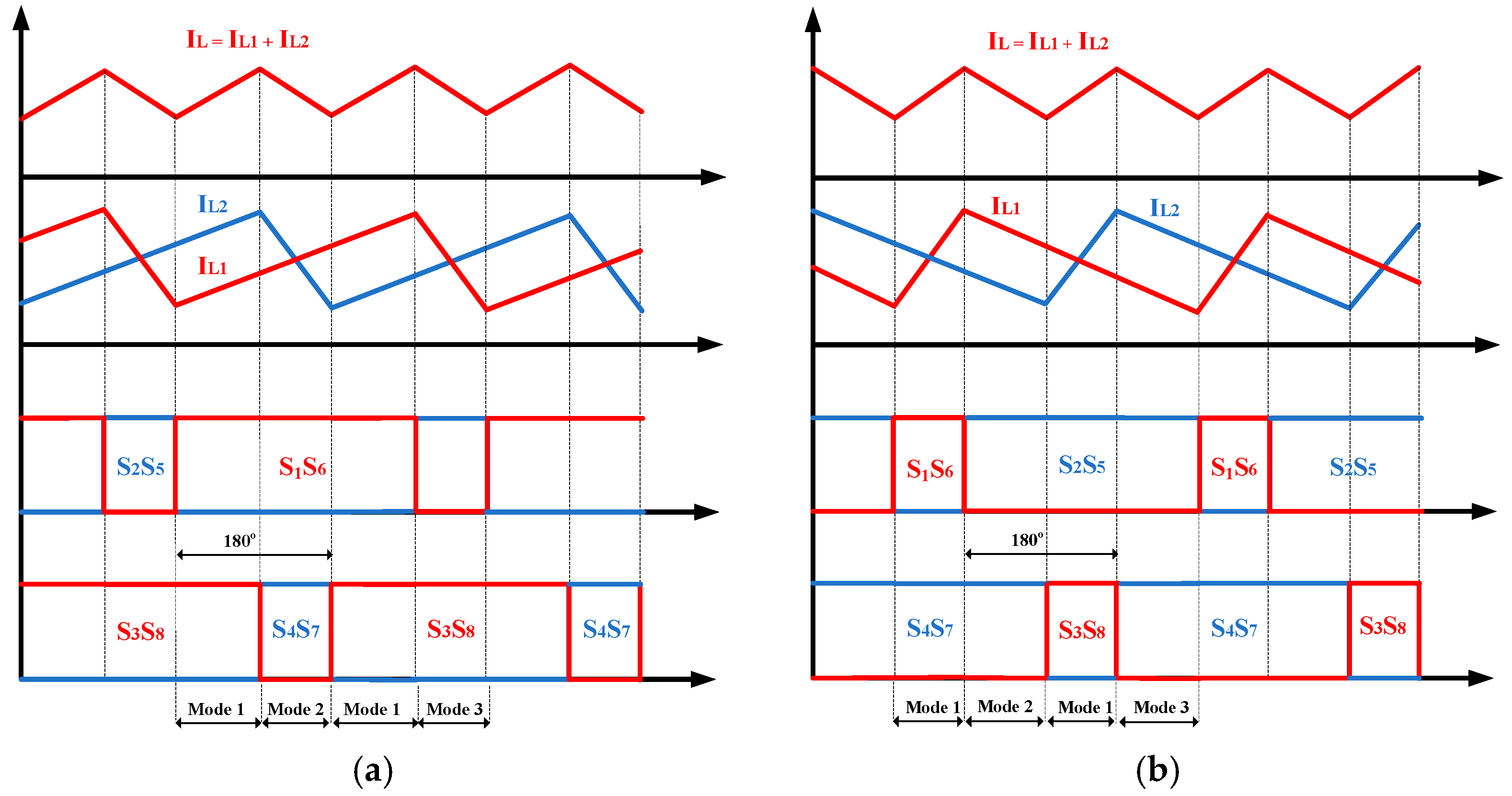
2.1. Interleaved Bipolar PWM

  • Pulse pattern analysis
In the IB-PWM method, the modulation indexes m1, and m2 are applied for H-Bridge 1 (H1) and H-Bridge 2 (H2), as shown in Figure 3, and they are assumed to be equal in the ideal case. Due to the rule of the traditional Bipolar PWM, in terms of the H1, a sawtooth carrier-based signal is compared to the modulation index m1 to create the control signal for switches S1 and S6, while inverted signals are used for S2 and S5. With regard to the H2, the phase of the sawtooth signal is shifted by 180° from that of H1, so-called the “Interleaved Bipolar PWM”, and the control signals for switches S3, S8, S4, and S7 are created similarly. The pulse diagram for this modulation method is presented in Figure 4.
  • Common-mode voltage analysis
Due to the 180° out of phase between the two carriers, the control signals for S1 and S3 are interleaved. In addition, assuming that the modulation indexes of two bridges are the same, the turn-on interval in a switching period of S1 is equal to that of S3. Therefore, the output voltages of two inverters are shifted by 180° in phase.
Defining that s1, s2, s3, s4 are the switching states of the switches S1, S2, S3, S4, correspondingly, the voltage v A N , v B N , v C N , v D N can be written in terms of switching states, as follows:
v A N = s 1 V A N + ( 1 s 1 ) V O N = s 1 V d c + V O N v B N = s 2 V d c + V O N v C N = s 3 V d c + V O N v D N = s 4 V d c + V O N
By applying Kirchhoff’s voltage law at the output of the inverter:
v A N = L 1 d i L 1 2 + v s v B N = L 3 d i L 3 2 v C N = L 2 d i L 2 2 + v s v D N = L 4 d i L 4 2
Assuming that the split-inductor currents are balanced: i L 1 = i L 3 ,   i L 2 = i L 4 , the common-mode voltage can be calculated from Equations (1) and (2) as follows:
v O N = ( s 1 + s 2 + s 3 + s 4 ) V d c 4 + v s 2
Each phase voltage takes the value of +Vdc when the upper switch is on and 0 V when this switch is off. According to the pulse diagram in Figure 4, in a switching period, there are always two turned-on upper switches and two turned-off upper switches, which means the common voltage can be defined as
v C M _ I B P W M = v s 2 V d c 2
Because V d c 2 is the constant component, the leakage current with the IB-PWM method only depends on the sinusoidal output voltage at the fundamental frequency of 50 Hz.
  • Ripple of the split-inductor current and the output current
According to the traditional bipolar PWM, each bridge has two operation modes. In mode 1, taking H1 for instance, as depicted in Figure 4, switches S1 and S6 are on, the output voltage of H1 is +Vdc, and the inductor currents iL1 and iL3 increase, while in mode 2, switches S2 and S5 are on, the output voltage of H1 is −Vdc, and the inductor currents iL1 and iL3 decrease. Because of the interleaved feature of the IB-PWM method, the two bridges of the IFB converter operate independently; therefore, the IFB converter with the IB-PWM method has four operation modes.
Table 1 synthesizes the comprehensive operation modes, along with the switching states of all switches of the IFB converter, applying various PWM techniques: the IB-PWM, the IU-PWM, and the ID-PWM. In this section, the equivalent circuit of each operation mode and the current ripple with the IB-PWM in each case are focused. The time intervals of mode 1, 2, 3, 4, 5, 6, 7, and 8 in a switching period Ts are defined as D1Ts, D2Ts, D3Ts, D4Ts, D5Ts, D6Ts, D7Ts, and D8Ts, respectively.
To determine the current ripple, the modulation indexes for the two bridges are equal, and the effect of deadtime is neglected. In this case, the turn-on interval in one switching period of two switches S1 and S3 are the same, which is defined as DTs.
-
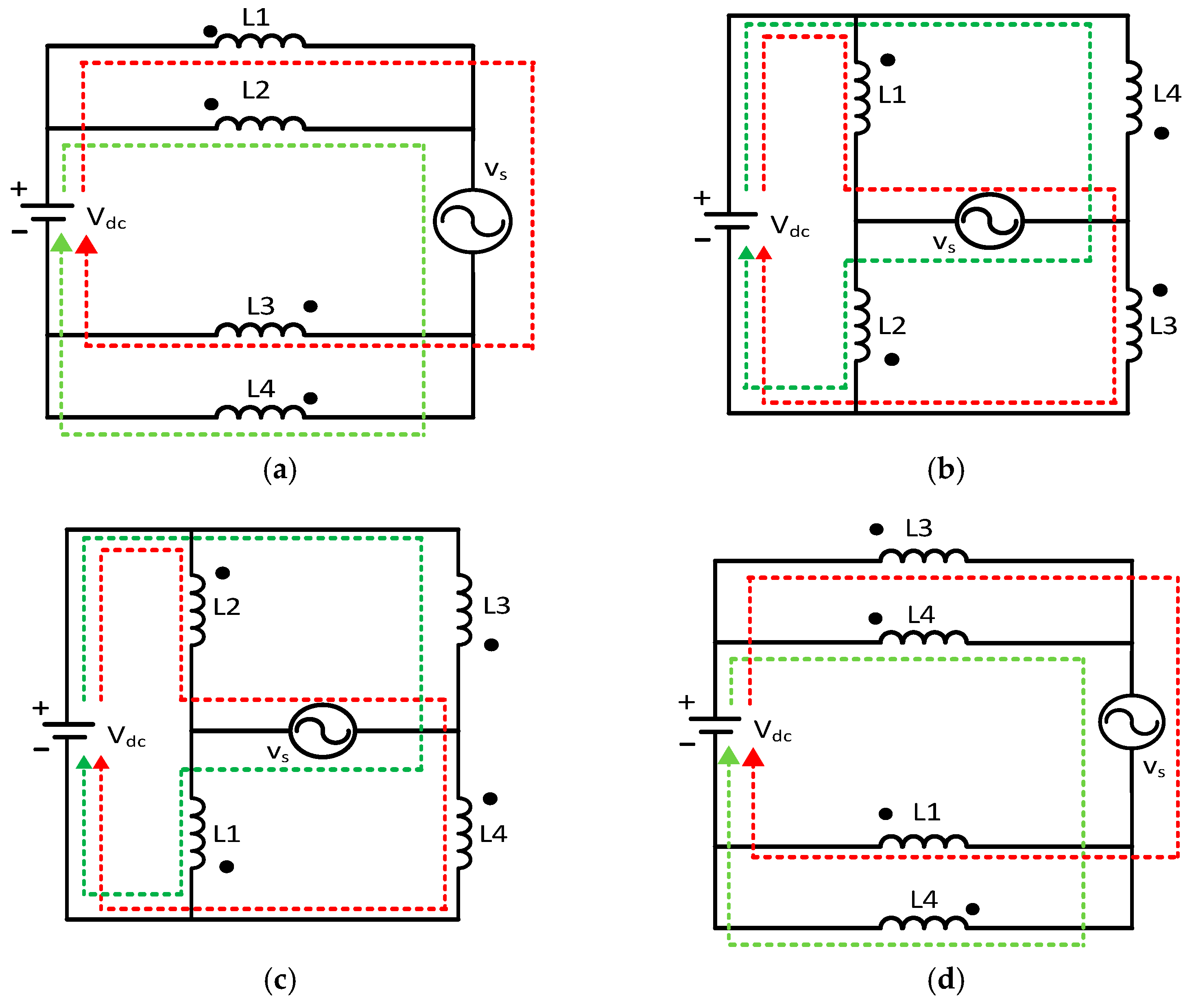
With D > 0.5 (Vs > 0): The IFB converter works in modes 1, 2, and 3.
In mode 1, both the split-inductor current iL1, iL2, and the output current iL increase. For the sake of intuition, the current ripple of iL is calculated in this case.
Because two bridges operate separately with the IB-PWM, based on the equivalent circuit in Figure 5a–c, all the split-inductor currents increase in the interval of DTs. Hence, the ripple of each inductor current is given as
Δ i L 1 _ I B = Δ i L 3 _ I B = V d c v s L 1 + L 3 D T = V d c v s 2 L D T s Δ i L 2 _ I B = Δ i L 4 _ I B = V d c v s L 2 + L 4 D T s = V d c v s 2 L D T s
The time interval for the increase in the output current in a switching period is determined in the Figure 4a: D s T s = ( D 0.5 ) T s . Therefore, the output current ripple when D > 0.5 is determined as
Δ i L _ I B = ( Δ i L 1 _ I B D T s + Δ i L 2 _ I B D T s ) D s T s = V D C v s 2 L × 2 × ( D 0.5 ) T s = V D C v s 2 L × ( 2 D 1 ) T s
Inherently, Δ i L _ I B < Δ i L 1 _ I B when D < 1, which means the interleaved PWM method has the ability to reduce the output current ripple. The decrease in the current ripple significantly reduces the THD of the output current, which is the advantage of the interleaved PWM method in general and the IB-PWM in particular.
-
With D < 0.5 (Vs < 0): the IFB converter operates in modes 2, 3, and 4.
In mode 4, both the split-inductor current iL1, iL2, and the output current iL decrease. For the intuitive approach, the ripple of iL is calculated in this case.
Because two bridges operate separately with the IB-PWM, based on the equivalent circuit in Figure 5b–d, the split-current increases in the interval of (1 - D)Ts. Hence, the ripple of each inductor current is given as
Δ i L 1 _ I B = Δ i L 3 _ I B = V d c v s L 1 + L 3 ( 1 D ) T s = V d c v s 2 L ( 1 D ) T s Δ i L 2 _ I B = Δ i L 4 _ I B = V d c v s L 2 + L 4 ( 1 D ) T = V d c v s 2 L ( 1 D ) T s
The time interval for the decrease in the output current in a switching period is determined from the Figure 4b: D s = 0.5 D . Therefore, the output current ripple when D < 0.5 is calculated as:
Δ i L _ I B = ( Δ i L 1 _ I B D T s + Δ i L 3 _ I B D T s ) D s T s = V D C v s 2 L × 2 × ( 0.5 D ) T s = V D C v s 2 L × ( 1 2 D ) T s
Here, we have Δ i L _ I B < Δ i L 1 _ I B since D > 0, which means the ripple of the output current is smaller than that of the split-inductor current.

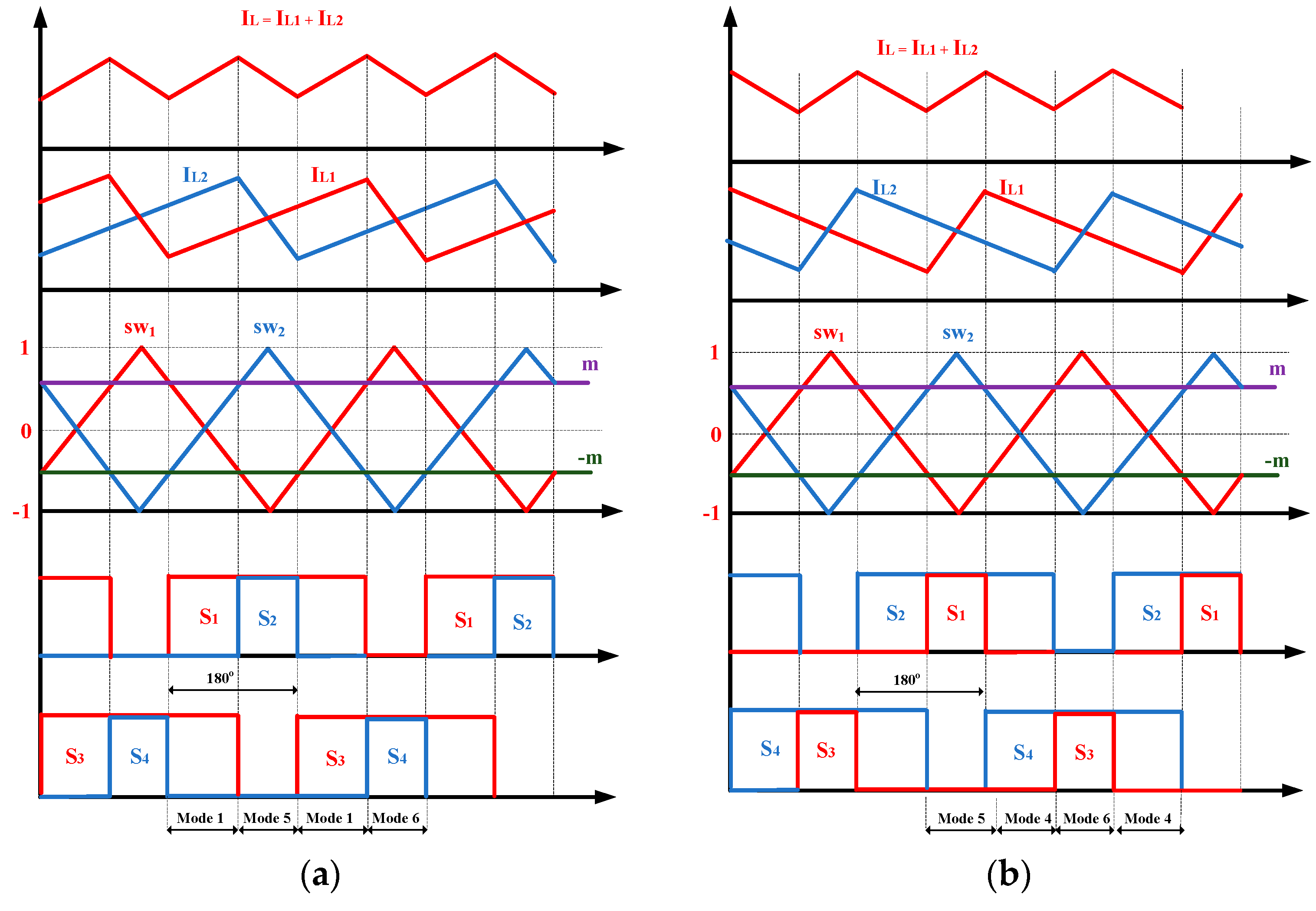
2.2. Interleaved Unipolar PWM

  • Pulse pattern analysis
The modulation rule for each H-Bridge is based on the traditional Unipolar PWM as shown in Figure 6. Taking the H-Bridge 1, for example, the modulation indexes m1 and -m1 are compared to the carrier sw1 to generate the control signals for S1 and S2, respectively. By inverting the logic of control signals S1 and S2, the signals for S5 and S6 are achieved, respectively. In terms of H-Bridge 2, the control signals for S3, S4, S7, and S8 are generated by a similar rule with the modulation index m2 (m2 is chosen to be equal to m1 in the ideal case), and the carrier sw2 shifted 180° in phase with the sw1 of H1.
The pulse pattern of the IB-PWM method is shown in Figure 7. An important feature that should be noted is that due to the symmetric feature, for example, when D > 0.5 (D is defined as in Section 2.1), the turn-on interval of both switches S1 and S2 overlaps the turn-off interval of both switches S3 and S4. As a result, at a moment in a switching period, there are two turn-on upper switches and two turn-off upper switches. Therefore, similar to the IB-PWM method, the common voltage of the IFB converter with the IU-PWM method can be defined from Equation (3):
v C M _ I U P W M = v s 2 V D C 2
As a result, the common-mode voltage with the IU-PWM is high-frequency pulse-free and only depends on the sinusoidal output voltage at the fundamental frequency of 50 Hz.
  • Ripple of the split-inductor current and the output current
    -
    With D > 0.5 (Vs > 0): The IFB converter operates in modes 1, 5, and 6.
Different from the IB-PWM method, there is a current loop flowing through one branch of the H1 and another branch of the H2, as shown in mode 5 and mode 6 in Figure 8.
Hence, the current ripple with the IU-PWM should be calculated in each mode instead of the whole DTS interval with the IB-PWM. The split-inductor current ripple in mode 1 is given by
Δ i L 1 _ I U = Δ i L 3 _ I U = V d c v s L 1 + L 3 D 1 T s = V d c v s 2 L ( D 0.5 ) T s Δ i L 2 _ I U = Δ i L 4 _ I U = V d c v s L 2 + L 4 D 1 T s = V d c v s 2 L ( D 0.5 ) T s
The split-inductor current ripple in mode 5 is given by
Δ i L 1 _ I U = Δ i L 4 _ I U = V d c v s L 1 + L 4 D 5 T s = V d c v s 2 L ( 1 D ) T s Δ i L 2 _ I U = Δ i L 3 _ I U = V d c v s L 2 + L 3 D 5 T s = V d c v s 2 L ( 1 D ) T s
The split-inductor current ripple in mode 6 is given by
Δ i L 1 _ I U = Δ i L 4 _ I U = V d c v s L 1 + L 4 D 6 T s = V d c v s 2 L ( D 0.5 ) T s Δ i L 2 _ I U = Δ i L 3 _ I U = V d c v s L 2 + L 3 D 6 T s = V d c v s 2 L ( D 0.5 ) T s
Because all the currents flowing through the four split-inductors are balanced, the current ripple Δ i L 1 _ I U of split-inductor L1 is chosen. The split-inductor current ripple is determined from Equations (10) and (11):
Δ i L 1 _ I U = V d c v s 2 L ( 2 D 1 + D 5 ) T s = V d c v s 2 L ( 2 ( D 0.5 ) + 1 D ) T s = V d c v s 2 L D T s
In mode 1, both the split-inductor current iL1, iL2 and the output current iL increase. For the intuitive approach, the output current ripple is determined in this mode:
Δ i L _ I U = ( Δ i L 1 _ I U D T s + Δ i L 2 _ I U D T s ) D s T s = V d c v s 2 L × 2 × ( D 0.5 ) T s = V d c v s 2 L × ( 2 D 1 ) T s
Compared to Equations (4) and (6), Δ i L _ I B = Δ i L _ I U and Δ i L 1 _ I B = Δ i L 1 _ I U . It can be noted that even though the pulse patterns of the IB-PWM and IU-PWM techniques are different when D > 0.5, the inductor current ripple and the output current ripple of the two modulation methods are the same.
-
With D < 0.5 (Vs < 0): The IFB converter operates in modes 4, 5, and 6.
The current ripple through split-inductor L1 is determined from Equations (12) and (13):
Δ i L 1 _ I U = V d c v s 2 L ( 2 D 4 + D 6 ) T s = V d c v s 2 L ( 1 2 D + D ) T s = V d c v s 2 L ( 1 D ) T s
The output current ripple is determined as
Δ i s = V d c v s 2 L × 2 × ( 0.5 D ) T s = V d c v s 2 L × ( 1 2 D ) T s

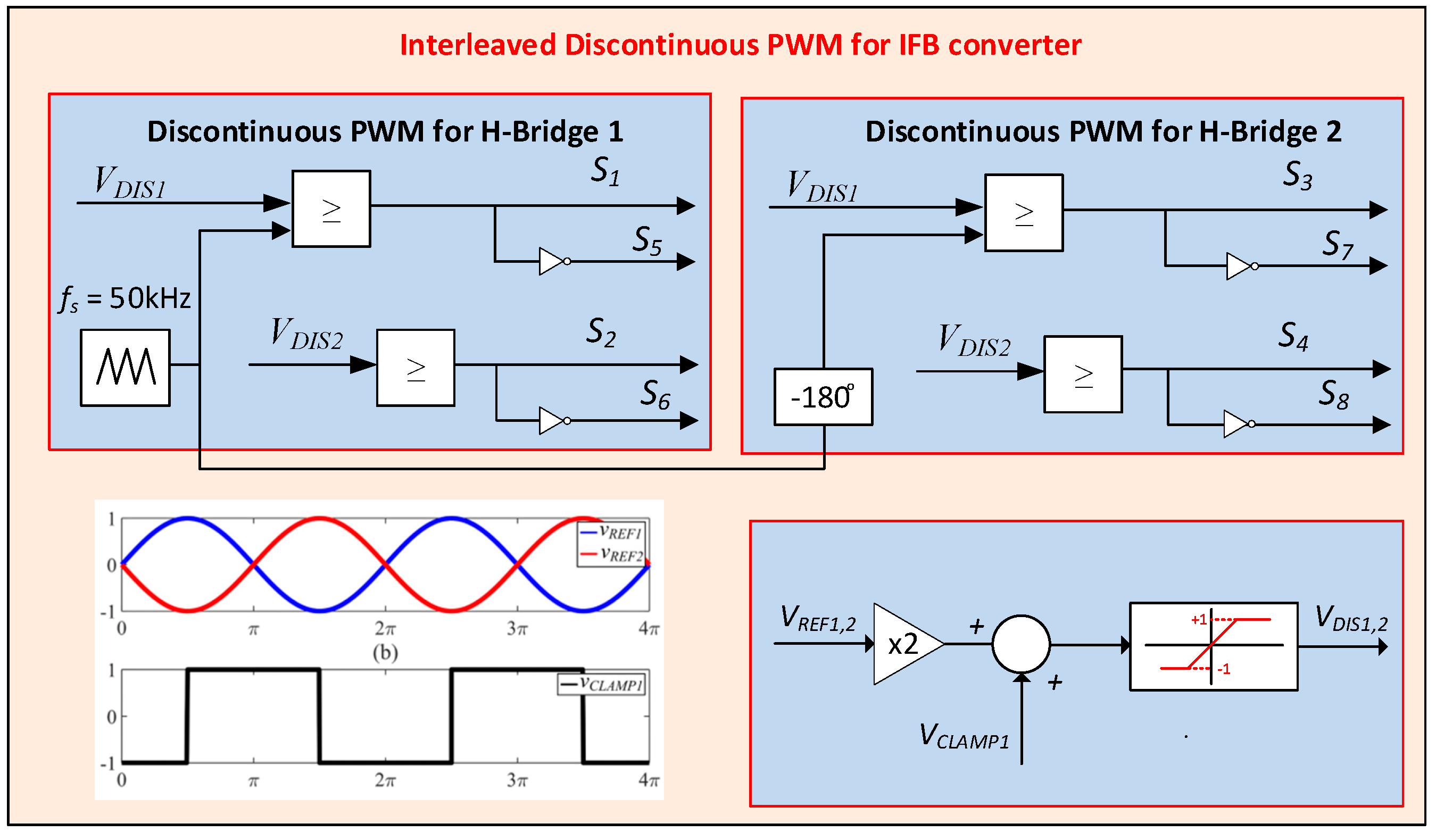
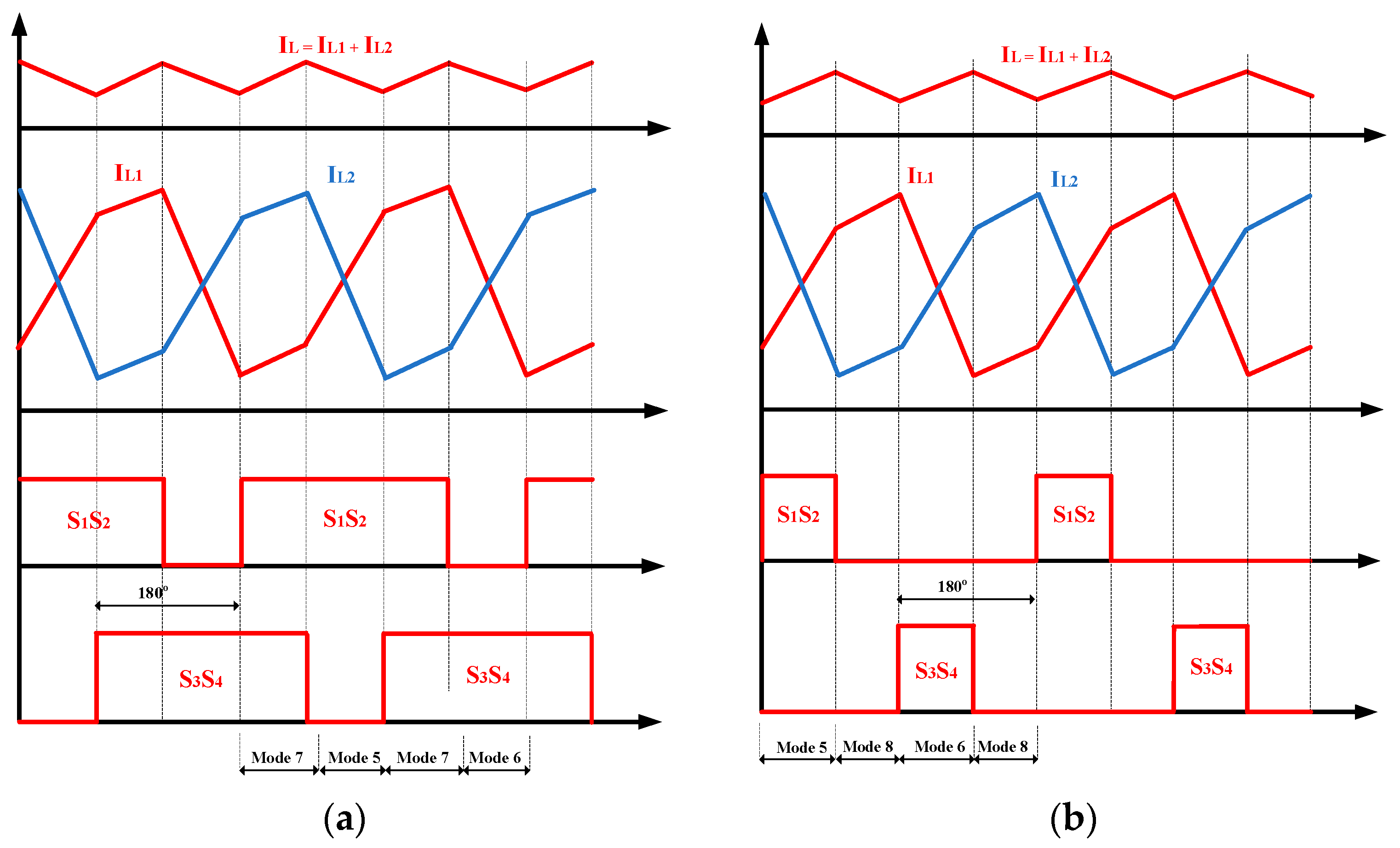
2.3. Interleaved Discontinuous PWM

  • Pulse pattern analysis
The discontinuous PWM method consists of two types: the DPWM1P method and the DPWM2P method [16], as shown in Figure 9, which is applied for a single H-Bridge converter. Because of the similar features of these types, this paper chooses the DPWM1P in combination with the interleaved technique, the so-called “Interleaved Discontinuous PWM”, for the IFB converter to compare the other interleaved PWM methods. In the ID-PWM method, a clamp signal Vc, which is synchronous with the AC voltage Vs, is created. The double modulation index is added with the clamp signal, which is saturated from −1 to 1 to obtain the discontinuous signal VDIS. This signal is compared to the carrier, taking the H1, for instance, to generate control signals for switches S1 and S3, while those for switches S5 and S6 are inverted. Similarly, the control signal for the switches S3, S4, S7, and S8 is generated with the carrier being shifted 180° in phase from that of H1.
  • Common-mode voltage analysis
The pulse pattern of the IU-PWM is shown in Figure 10. As can be seen, in a switching period, there are two or no turn-on upper switches when D < 0.5, while there are two or four turned-on upper switches when D > 0.5. Therefore, unlike the IB-PWM and IU-PWM, the common mode voltage of the IFB converter can take one of these values: 0, Vdc/2, and Vdc. This high-frequency voltage component increases the leakage current of the converter [20]:
i l k = C p d v C M V d t
In which the parasitic capacitor Cp consists of several parasitic capacitors Cp1, Cp2, and Cp3, as shown in Figure 2.
  • Ripple of the split-inductor current and output current
The current ripple with the IU-PWM is analyzed in two intervals: non-switching interval (accounts for half of the Vs cycle) and switching interval (accounts for the other half of the Vs cycle).
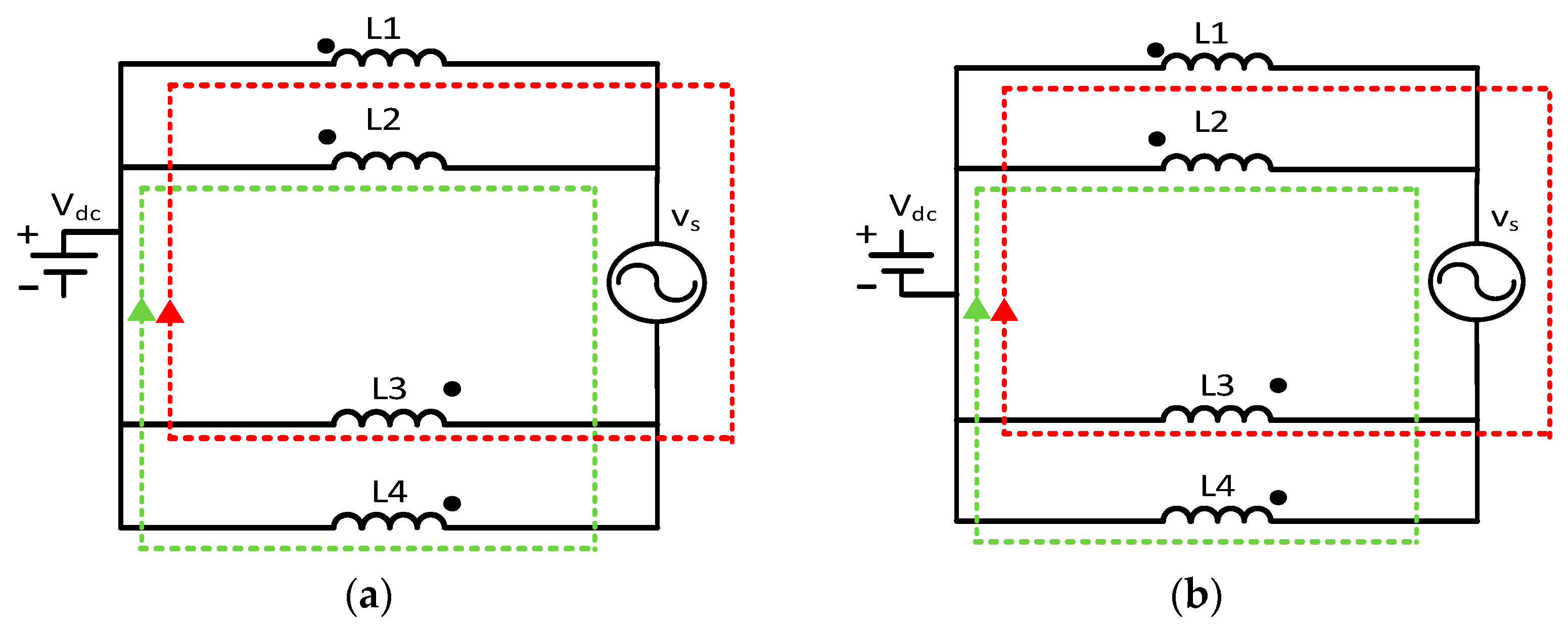
  • Non-switching interval: Due to the discontinuous PWM rule, all the upper switches S1, S2, S3, and S4 are on or off in this interval, hence, the currents through the four split-inductors are in phase and the current ripples seem to be zero.
  • Switching interval: In some modes of this interval, the currents only flow through the inductor and Vs. Therefore, the sign of Vs decides whether the current increases or decreases. In this section, the current ripples are analyzed when Vs < 0, while the analysis when Vs > 0 is similar. Unlike the previous interleaved PWM method, the inductor currents with the ID-PWM increase or decrease with the different rates in the different modes.
-
With D > 0.5: The IFB converter operates in modes 5, 6, and 7.
Similar to the IU-PWM, there is a current loop flowing through one branch of the H1 and another branch of the H2, as shown in mode 5 and mode 6 in Figure 10.
The split-inductor current ripple in mode 5 is given by
Δ i L 1 _ I D = Δ i L 4 _ I D = V d c v s L 1 + L 4 D 5 T s = V d c v s 2 L ( 1 D ) T s Δ i L 2 _ I D = Δ i L 3 _ I D = V d c v s L 2 + L 3 D 5 T s = V d c v s 2 L ( 1 D ) T s
The split-inductor current ripple in mode 6 is given by
Δ i L 1 _ I D = Δ i L 4 _ I D = V d c v s L 1 + L 4 D 6 T s = V d c v s 2 L ( 1 D ) T s Δ i L 2 _ I D = Δ i L 3 _ I D = V d c v s L 2 + L 3 D 6 T s = V d c v s 2 L ( 1 D ) T s
The split-inductor current ripple in mode 7 is given by
Δ i L 1 = Δ i L 3 = v s L 1 + L 3 ( D 0.5 ) T s = v s 2 L ( D 0.5 ) T s Δ i L 2 = Δ i L 4 = v s L 2 + L 4 ( D 0.5 ) T s = v s 2 L ( D 0.5 ) T s
In mode 8, both the split-inductor currents iL1, iL2 and the output current iL decrease as shown in Figure 11. For the intuitive approach, the output current ripple is determined in this mode.
Because all the currents flowing through the four split-inductors are balanced, the current ripple of split-inductor L1 is chosen. The split-inductor current ripple is determined from Equations (18) and (19):
Δ i L 1 _ I D = V d c v s 2 L × D 5 T s + v s 2 L × 2 D 7 T s = V d c v s 2 L × ( 1 D ) T s + v s 2 L × ( 2 D 1 ) T s = V d c v s 2 L × D T s + v s 2 L × ( 2 D 1 ) T s
The output current ripple is determined as
Δ i L = Δ i L 1 + Δ i L 2 = v s 2 L × 2 D 7 T s = v s 2 L × ( 2 D 1 ) T s
-
With D < 0.5: The IFB converter operates in modes 5, 6, and 8.
The split-inductor current ripple in mode 8 is given by
Δ i L 1 = Δ i L 3 = v s L 1 + L 3 ( 0.5 D ) T s = v s 2 L ( 0.5 D ) T s Δ i L 2 = Δ i L 4 = v s L 2 + L 4 ( 0.5 D ) T s = v s 2 L ( 0.5 D ) T s
The split-inductor current ripple is determined from Equations (19) and (20):
Δ i L 1 _ I D = V d c v s 2 L × D 6 T s = V d c v s 2 L × D T s
The output current ripple is determined as
Δ i L = Δ i L 1 + Δ i L 2 = v s 2 L × 2 D 8 T s = v s 2 L × ( 1 2 D ) T s

2.4. Theorectical Comparion among Three Interleaved PWM Methods for the IFB Converter

To begin with, the stress voltage on the switches of the IFB converter is the same for all PWM methods. In terms of current, the current stress on each switch depends on the form of the corresponding split-inductor current, which was analyzed in each PWM method. The inductor current ripple Δ i L 1 , output current ripple Δ i L , and the high-frequency component of the common voltage v C M of the IFB converter, applying three PWM techniques, are synthesized in Table 2. As can be seen in Table 2, first, the output current ripple is always smaller than the inductor current ripple for all methods, proving the effectiveness of the proposed interleaved modulation technique for the IFB converter particularly. In addition, even though the pulse patterns of the IB-PWM method and the IU-PWM method are different, the ripple of their inductor currents and output currents are the same.
Meanwhile, in this aspect, the ID-PWM method offers the smallest output current ripple, although its inductor current ripple could be smaller than that of other methods in the non-switching interval and be larger in the switching interval. As a result, the THD of the output current with the ID-PWM achieves the smallest value, while those of the IB-PWM and IU-PWM are equal. Second, while the common mode voltage with the IB-PWM and IU-PWM methods are free of high-frequency pulse, that of the ID-PWM additionally depends on the high-frequency pulse, which results in higher leakage current. Third, the reduction of the switching loss is the essential advantage of the ID-PWM compared to other methods. Obviously, the number of the commutations in one switching period is the same in the case of the IB-PWM and the IU-PWM method, while that of the ID-PWM is lower because its modulation index is clamped at the value of −1 or 1. Hence, the ID-PWM method has the smallest switching losses.
In the following sections, the power losses of three PWM methods are verified by simulation results, while the comparison of the current performance and common-mode voltage are verified by the experimental results.

3. Simulation Verification

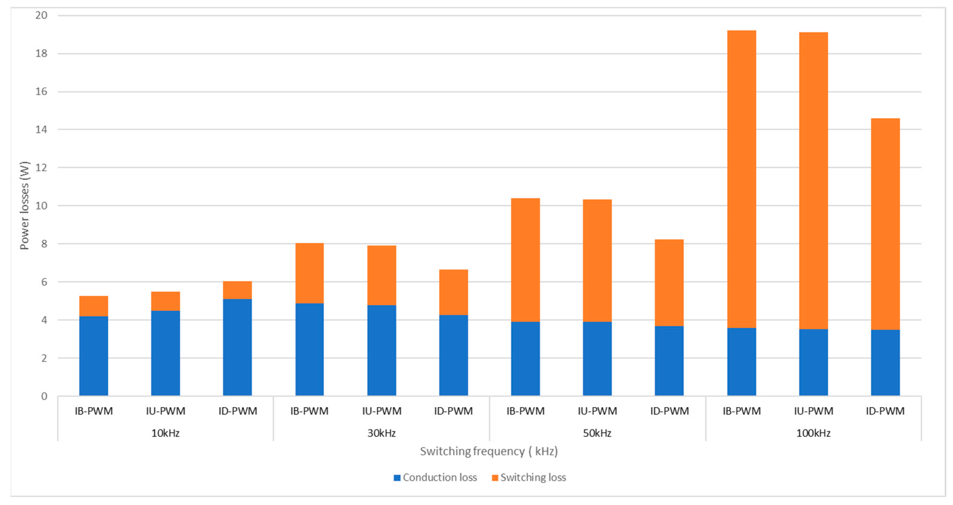
3.1. Power Losses Evaluation

To determine the Mosfet power loss and thermal analysis, a thermal model of the IFB converter was built along with the thermal model using PLECS. The print screen of the simulated circuit is shown in Figure 12. PLECS allows researchers to provide the necessary parameters for the loss estimation of power semiconductors as the threshold voltage, thermal impedance, and drain-source on-state resistance. These are and can be used for the numerical estimation of losses using equations or implemented in the form of lookup tables for the turn-on loss, the turn-off loss, and conduction loss [16,20]. The simulation parameters are presented in Table 3. The power loss is compared among three PWM methods with 2 scenarios in the open-loop mode: variable switching frequency and variable power rate.
  • Scenario 1:
In this scenario, while the power rate is set up at 1.5 kW, which is similar to the experimental scenario, the switching frequency varies among 10 kHz, 30 kHz, 50 kHz, and 100 kHz.
As shown in Figure 13, the conduction losses of all three PWM methods for the IFB converter are similar with multiple chosen switching frequencies. Whereas, the switching losses increases significantly when the switching frequency increases. Moreover, at the low frequency of 10 kHz, the switching loss in three PWM methods is almost the same; however, that of the ID-PWM is significantly smaller than those of other interleaved methods. In detail, the reductions of around 23%, 30% and 27% in the switching loss of the IU-PWM are achieved in comparison with other methods at the switching frequency of 30 kHz, 50 kHz and 100 kHz, respectively.
  • Scenario 2:
In this scenario, while the switching frequency is set up at 30 kHz, which is similar to the experimental scenario, the power rate varies among 1.5 kW, 5 kW, 7.5 kW, and 10 kW. As shown in Figure 14, while the conduction losses of all three PWM methods for the IFB converter are still similar at any specific power rate, there is a difference among the switching losses. In detail, the reductions of around 25%, 24.8%, 25%, and 28% in the switching loss of the IU-PWM are achieved in comparison with those of other methods at the power rate of 1.5 kW, 5 kW, 7.5 kW, and 10 kW, respectively.

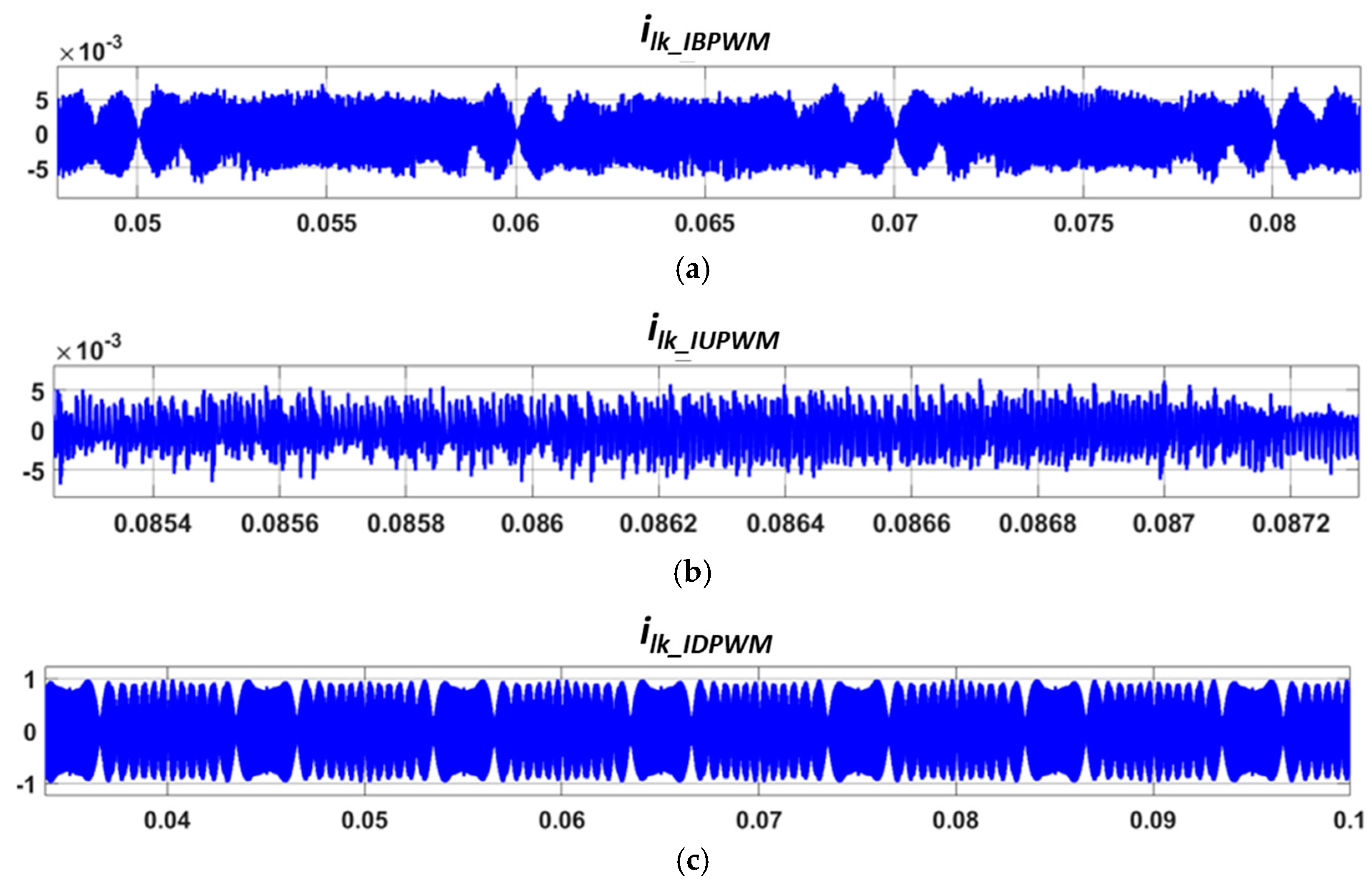
3.2. Leakage Current Comparisons

The parasitic capacitors normally have a small value; however, the accurate value is difficult to determine in a practical product. In this research, for simulation verification, the parameter of a parasitic RC branch is taken, as in [11] (R = 5 Ohms and C = 800 pF), which connects point O and point N, as in Figure 2. The high-frequency component in the common-mode voltage in the previous theoretical analysis leads to the different results among the leakage current of three methods, as shown in Figure 15.
In detail, the root mean square (RMS) values of the leakage current with the IB-PWM and IU-PWM methods are relatively small at 2.29 mA and 2.39 mA, and the statistics for peak value are just 7.2 mA and 6.7 mA, respectively. Additionally, the RMS value and peak value of the leakage current in the case of the IU-PWM are much higher, at 470 mA and 980 mA. These values are out of standard IEC/EN 60335-1 [21] for leakage current in the domestic applications, which results in safety problems and electromagnetic emissions.

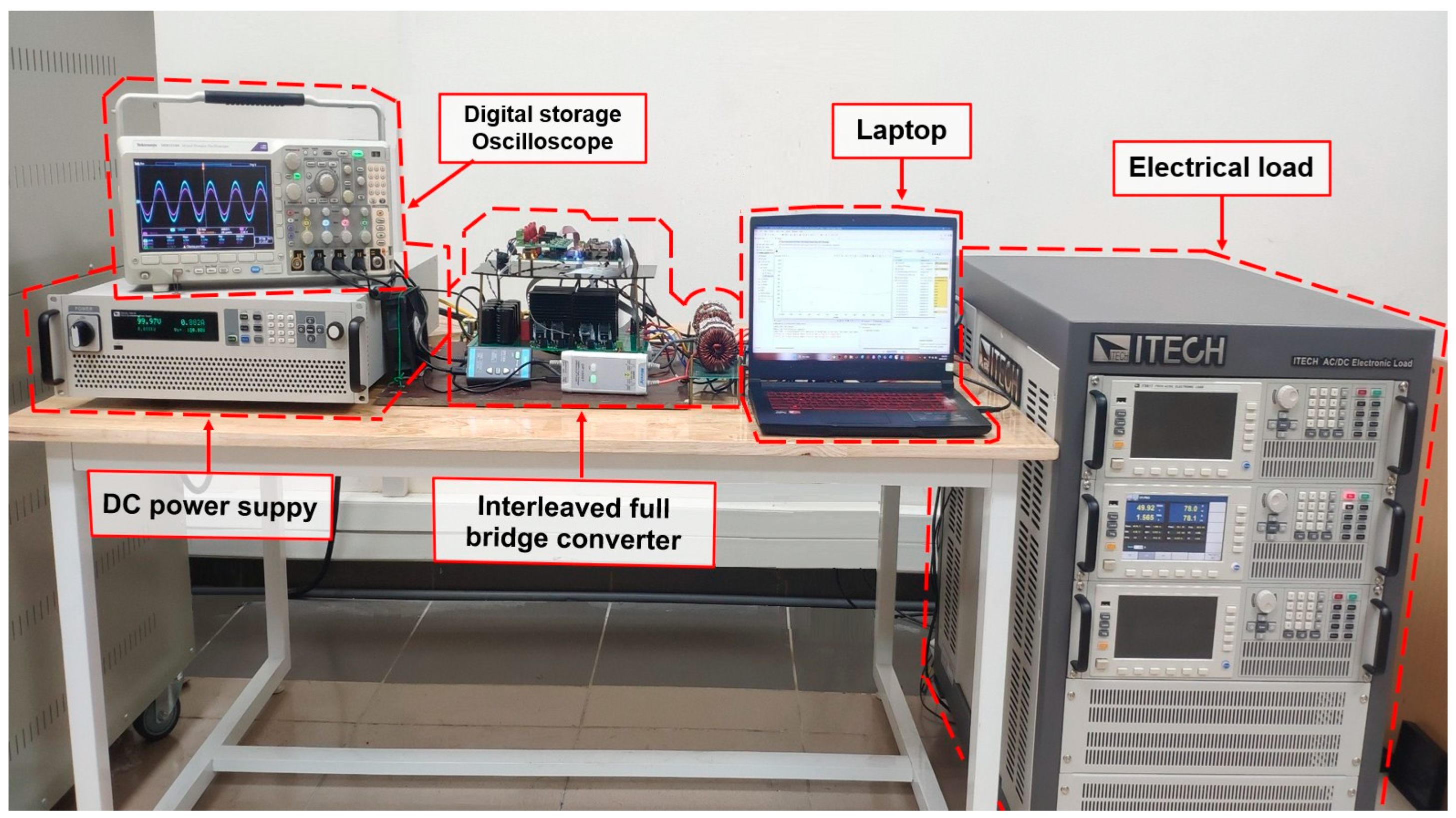
4. Experiment Verification

To clarify the comparison among the three proposed PWM methods, a 1.5 kW experimental prototype for the IFB converter was implemented. The experimental system shown in Figure 16 includes the IFB converter inverter, filtered inductor, a programmable electronic load ITECH IT8617, and a DC power supply model ITECH IT6018C-1500-40. The control algorithm is programmed in control kit Launchpad TMS320F28379D. To display and collect the data, a GW INSTEK GDS-2104A Digital Oscilloscopes is utilized with the current probe Micsig CP2100A and the isolated voltage probe Micsig DP10013. Except for a lower power rate of 1.5 kW, the two experimental scenarios in open-loop mode are carried out with similar parameters of the PLECS simulation in Table 3.
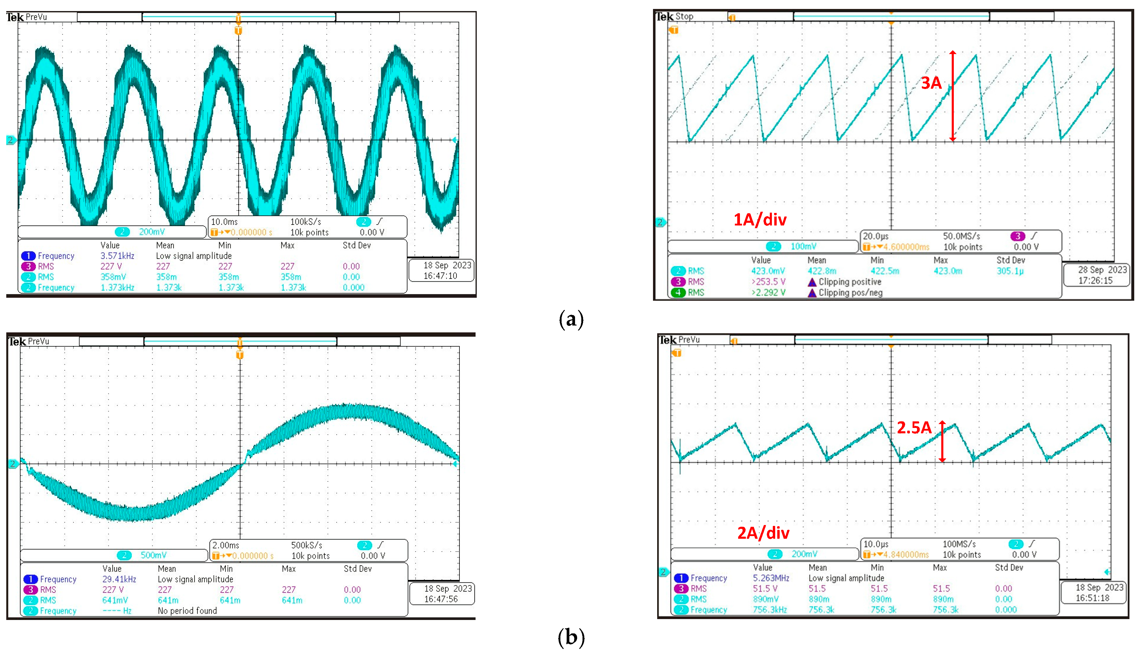
  • Output current performance evaluation
The current responses are shown in Figure 17, Figure 18 and Figure 19. Overall, the currents through the split inductor L1 and L2 are interleaved, which leads to the output current ripple being smaller than the inductor current ripple. In detail, the largest peak-to-peak current ripples of the split-inductor with the IB-PWM, IU-PWM, and ID-PWM are approximately 3 A, 3 A, and 5 A, respectively. These results show good agreement with the theoretical analysis in Section 2. In addition, the output current ripples with these three PWM methods are 2.5 A, 2.5 A and 1.8A, respectively, which proves the effectiveness of the interleaved technique for reducing the output current ripple. Moreover, the ID-PWM gives the smallest output current ripple as the aforementioned theory.
To that extent, the THD of the output currents with three methods are compared in Figure 20. The part highlighted in red indicates the portion used for THD analysis. The harmonic spectrum is displayed as a bar graph relative to the fundamental frequency. While the THD current of the IB-PWM and the IU-PWM are equal at 9.76%, that of the IU-PWM is significantly smaller at 5.85%. To achieve a similar THD current as the ID-PWM, the switching frequency has to increase by 1.7 times or the inductance increases by 1.7 times. This produces higher switching loss, which decreases the total efficiency or increases the volume of the passive component, as well as reduces the power density. This also inherently illustrates the economic benefit of the IU-PWM for the IFB converter.
Notably, the experimental and simulation results have proven the theoretical analysis. The advantage of lower power losses is achieved with the ID-PWM method for the IFB converter. Moreover, while the traditional discontinuous PWM does not improve the performance of the output current of the full bridge converter, the proposed ID-PWM offers a significant reduction in the THD current of the IFB converter compared to other interleaved PWM methods.
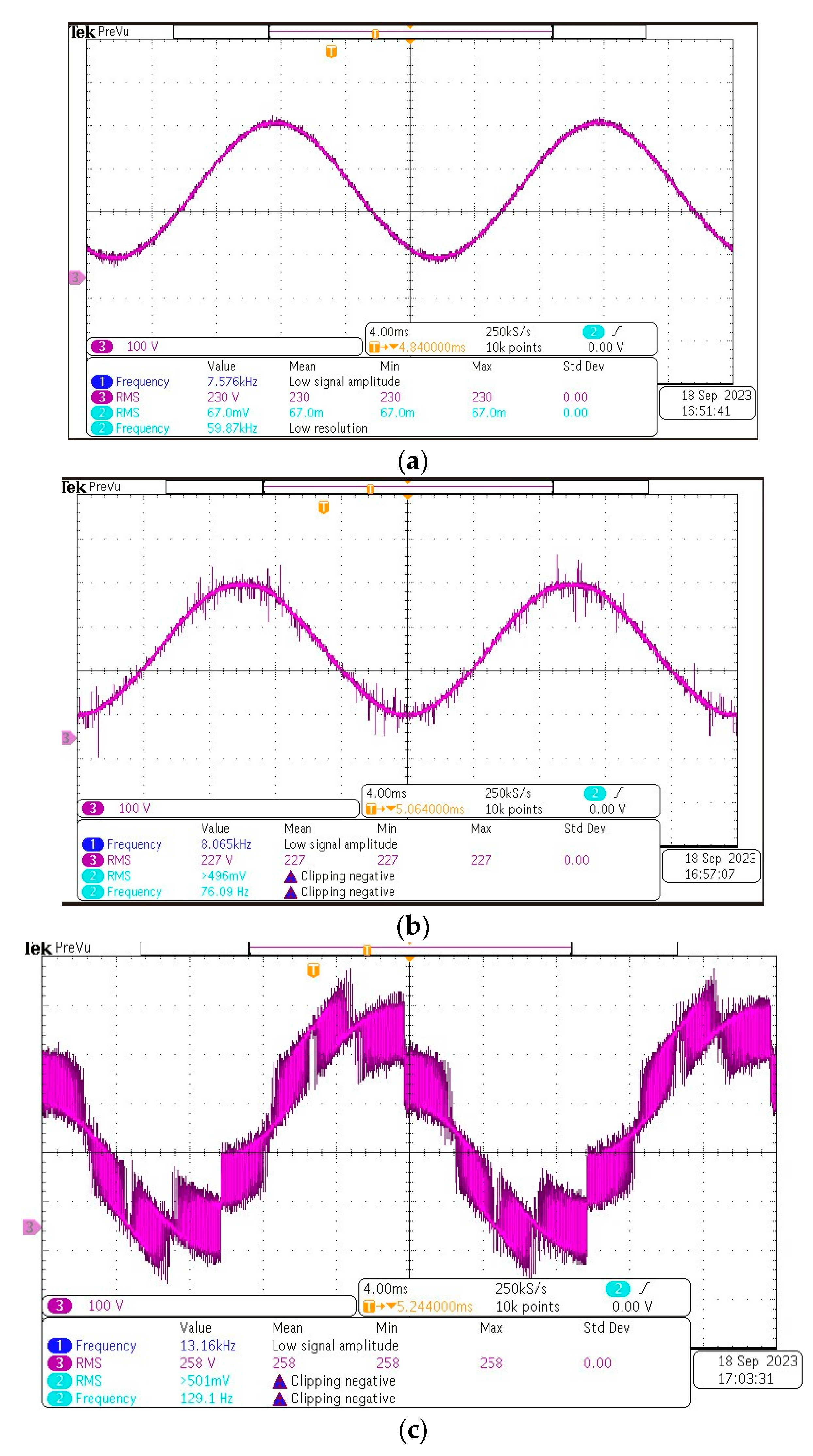
  • Common-mode voltage discussion
In the experimental prototype, an open-frame IFB inverter is tested in which the parasitic capacitor is not taken into consideration due to the lack of the product chassis. Therefore, the leakage current responses are evaluated through the common-mode voltage. It can be seen that the common-mode voltage in Figure 21a for the IB-PWM method and in Figure 21b for the IU-PWM method are free of high-frequency pulses and they have the sinusoidal waveform for half of the grid voltage, with the offset being half of the DC voltage. However, high-frequency noise superimposes on a sinusoidal voltage in the measured negative poles of DC bus-to-ground voltage with IU-PWM in Figure 21c. In this case, high dv/dt could inject a spiky current with large di/dt through the parasitic capacitances and exceed the safety limitation for the leakage current in a household appliance in the IEC/EN 60335-1 standard [21]. To maintain the advantage of the ID-PWM method for the IFB converter, some hardware solutions could be considered.
An EMI filter [22] is a traditional solution for the leakage current. In [23,24], the DC–bus midpoint is connected to the LCL filter capacitor midpoint in order to effectively reduce the DC–side leakage current. An integrated common-mode (CM) and different-mode filter with passive damping is proposed in [25] for grid-connected single-phase power converters for PV systems. Furthermore, an active CM filter is proposed in [26] for reducing the ground leakage current, but additional magnetic components and computational burden are required. Additionally, some modifications in structure by adding extra devices are applied in much of the research concerning full bridge converters. The H6 converter in [27] uses two additional switches, which would be turned off during the freewheeling period to disconnect the inverter from the DC source. The improvement of this structure can be mentioned in [28], with two additional diodes in the FB-DCBP inverter. Similarly, the AC side could also be bypassed with the HERIC inverter with two extra switching devices at the AC side [29].

5. Conclusions

This paper proposes three PWM methods, along with a comprehensive comparison of the interleaved full bridge converter in an AC Battery application. These PWM methods are IB-PWM, IU-PWM, and ID-PWM, namely, based on the traditional PWM method and the interleaved techniques method. The theoretical comparison among these PWM methods is also presented, and then, the simulation and experimental prototype are carried out to verify. The results prove that the IB-PWM and IU-PWM give a similar performance in output current ripple and THD, common-mode voltage, and power loss. The ID-PWM method not only achieves a reduction in the switching loss but also the lowest THD output current. However, different from the IB-PWM and IU-PWM, the common-mode voltage of the IFB converter using the ID-PWM consists of a high-frequency component, which results in a higher leakage current. This issue could be handled in a future work by hardware solutions, which allows this method to be the most suitable PWM method for the IFB converter.

Author Contributions

Conceptualization, P.V. and S.-J.A.; methodology, T.A.D.; software, T.A.D. and M.D.N.; validation, T.A.D., Q.D.N. and P.V.; formal analysis, T.A.D. and S.-J.A.; investigation, S.-J.A.; resources, Q.D.N.; data curation, M.D.N.; writing—original draft preparation, T.A.D.; writing—review and editing, S.-J.A. and P.V.; visualization, Q.D.N.; supervision, M.D.N.; project administration, S.-J.A. and P.V.; funding acquisition, S.-J.A. All authors have read and agreed to the published version of the manuscript.

Funding

This research was supported by “Regional Innovation Strategy (RIS)” through the National Research Foundation of Korea (NRF) funded by the Ministry of Education (MOE) (2021RIS-002); in part by the Korea Institute of Energy Technology Evaluation and Planning (KETEP) grant funded by the Korea government (MOTIE) (20225500000060).

Data Availability Statement

Data are contained within the article.

Conflicts of Interest

The authors declare no conflicts of interest.

References

  1. Li, J.; He, S.; Yang, Q.; Wei, Z.; Li, Y.; He, H. A Comprehensive Review of Second Life Batteries Towards Sustainable Mechanisms: Potential, Challenges, and Future Prospects. IEEE Trans. Transp. Electrif. 2022, 9, 4824–4845. [Google Scholar] [CrossRef]
  2. Zhao, Y.; Pohl, O.; Bhatt, A.I.; Collis, G.E.; Mahon, P.J.; Rüther, T.; Hollenkamp, A.F. A Review on Battery Market Trends, Second-Life Reuse, and Recycling. Sustain. Chem. 2021, 2, 167–205. [Google Scholar] [CrossRef]
  3. Simatupang, D.; Benshatti, A.; Park, S.-Y. Embedded Electrochemical Impedance Spectroscopy into Battery Management System. In Proceedings of the IECON 2021—47th Annual Conference of the IEEE Industrial Electronics Society, Toronto, ON, Canada, 13–16 October 2021; pp. 1–6. [Google Scholar]
  4. Hu, X.; Deng, X.; Wang, F.; Deng, Z.; Lin, X.; Teodorescu, R.; Pecht, M.G. A Review of Second-Life Lithium-Ion Batteries for Stationary Energy Storage Applications. Proc. IEEE 2022, 110, 735–753. [Google Scholar] [CrossRef]
  5. Yang, S.; Ma, X.; Bao, W.; Liu, J. Multiple-Function Control Strategy for Hybrid SLB-NB Energy Storage System. In Proceedings of the 2022 7th Asia Conference on Power and Electrical Engineering (ACPEE), Hangzhou, China, 15–17 April 2022; pp. 318–323. [Google Scholar] [CrossRef]
  6. Makhadmeh, S.N.; Al-Betar, M.A.; Alyasseri, Z.A.A.; Abasi, A.K.; Khader, A.T.; Damaševičius, R.; Mohammed, M.A.; Abdulkareem, K.H. Smart Home Battery for the Multi-Objective Power Scheduling Problem in a Smart Home Using Grey Wolf Optimizer. Electronics 2021, 10, 447. [Google Scholar] [CrossRef]
  7. Zich, J.; Jandik, J. Active Battery Management System for Home Battery Energy Storage. In Proceedings of the 2020 21st International Scientific Conference on Electric Power Engineering (EPE), Prague, Czech Republic, 19–21 October 2020; pp. 1–4. [Google Scholar] [CrossRef]
  8. Jiang, L.; Wang, X. Research on the Participation of Household Battery Energy Storage in the Electricity Peak Regulation Ancillary Service Market. Processes 2023, 11, 794. [Google Scholar] [CrossRef]
  9. Inamdar, S.; Thosar, A.; Mante, S. Literature Review of 3.3kW On Board Charger Topologies. In Proceedings of the 2019 3rd International conference on Electronics, Communication and Aerospace Technology (ICECA), Coimbatore, India, 12–14 June 2019; pp. 276–281. [Google Scholar]
  10. FMusavi, F.; Eberle, W.; Dunford, W.G. A high-performance single-phase AC-DC power factor corrected boost converter for plug in hybrid electric vehicle battery chargers. In Proceedings of the 2010 IEEE Energy Conversion Congress and Exposition, Atlanta, GA, USA, 12–16 September 2010; pp. 3588–3595. [Google Scholar] [CrossRef]
  11. Xia, Y.; Ayyanar, R. Comprehensive comparison of THD and common mode leakage current of bipolar, unipolar and hybrid modulation schemes for single phase grid connected full bridge inverters. In Proceedings of the 2017 IEEE Applied Power Electronics Conference and Exposition (APEC), Tampa, FL, USA, 26–30 March 2017; pp. 743–750. [Google Scholar] [CrossRef]
  12. Marandi, D.; Sowmya, T.N.; Babu, B.C. Comparative study between unipolar and bipolar switching scheme with LCL filter for single-phase grid connected inverter system. In Proceedings of the 2012 IEEE Students’ Conference on Electrical, Electronics and Computer Science, Bhopal, India, 1–2 March 2012; pp. 1–4. [Google Scholar] [CrossRef]
  13. Awais, M.; Yasin, A.R.; Riaz, M.; Saqib, B.; Zia, S.; Yasin, A. Robust Sliding Mode Control of a Unipolar Power Inverter. Energies 2021, 14, 5405. [Google Scholar] [CrossRef]
  14. Algaddafi, A.; Elnaddab, K.; Ma’Mari, A.; Esgiar, A.N. Comparing the Performance of Bipolar and Unipolar Switching Frequency to Drive DC-AC Inverter. In Proceedings of the 2016 International Renewable and Sustainable Energy Conference, Marrakech, Morocco, 14–17 November 2016. [Google Scholar] [CrossRef]
  15. Behera, P.K.; Das, S.; Pattnaik, M. Performance Comparison Between Bipolar and Unipolar Switching Scheme for a Single-Phase Inverter Based Stand-alone Photovoltaic System. In Proceedings of the 2019 IEEE 16th India Council International Conference, Rajkot, India, 13–15 December 2019; pp. 1–4. [Google Scholar] [CrossRef]
  16. Ferrer-Arnau, L.; Berbel, N.; Capella, G.J.; Zaragoza, J. Study of modulation techniques applied to full bridge single-phase inverters based on wide-bandgap semiconductors. In Proceedings of the IECON 2019—45th Annual Conference of the IEEE Industrial Electronics Society, Lisbon, Portugal, 14–17 October 2019; pp. 2032–2037. [Google Scholar] [CrossRef]
  17. Fernandez, M.; Robles, E.; Aretxabaleta, I.; Kortabarria, I.; Martín, J.L. Proposal of Hybrid Discontinuous PWM Technique for Five-Phase Inverters under Open-Phase Fault Operation. Machines 2023, 11, 404. [Google Scholar] [CrossRef]
  18. Hossameldin, A.A.; Abdelsalam, A.K.; Ibrahim, A.A.; Williams, B.W. Enhanced Performance Modified Discontinuous PWM Technique for Three-Phase Z-Source Inverter. Energies 2020, 13, 578. [Google Scholar] [CrossRef]
  19. Zhang, L.; Sun, K.; Xing, Y.; Zhao, J. Parallel Operation of Modular Single-Phase Transformerless Grid-Tied PV Inverters with Common DC Bus and AC Bus. IEEE J. Emerg. Sel. Top. Power Electron. 2015, 3, 858–869. [Google Scholar] [CrossRef]
  20. Kiranmai, K.S.P.; Damodaran, R.V.; Hushki, M.; Shareef, H. An alternate hybrid PWM for uniform thermal sharing in single phase voltage-source inverter. Sci. Rep. 2023, 13, 3348. [Google Scholar] [CrossRef] [PubMed]
  21. Available online: https://www.elipse.eu/wp-content/uploads/2020/10/White-Paper-Safety-Standards-Elipse-Oct-2020.pdf (accessed on 1 September 2023).
  22. Yang, Y.; Blaabjerg, F.; Wang, H. Low voltage ride-through of single-phase transformerless photovoltaic inverters. In Proceedings of the 2013 IEEE Energy Conversion Congress and Exposition, Denver, CO, USA, 15–19 September 2013; pp. 4762–4769. [Google Scholar] [CrossRef]
  23. Trzynadlowski, A.M. EMI Effects of power converters. In Power Electronics Handbook; Butterworth-Heinemann: Oxford, UK, 2007. [Google Scholar] [CrossRef]
  24. Wu, W.; Sun, Y.; Lin, Z.; He, Y.; Huang, M.; Blaabjerg, F.; Chung, H.S.-H. A Modified LLCL Filter With the Reduced Conducted EMI Noise. IEEE Trans. Power Electron. 2014, 29, 3393–3402. [Google Scholar] [CrossRef]
  25. Hedayati, M.H.; John, V. EMI and Ground Leakage Current Reduction in Single-Phase Grid-Connected Power Converter. IET Power Electron. 2017, 10, 938–944. [Google Scholar] [CrossRef]
  26. Figueredo, R.S.; de Carvalho, K.C.M.; Matakas, L. Integrated common and differential mode filter applied to a single-phase transformerless PV microinverter with low leakage current. In Proceedings of the 2014 International Power Electronics Conference (IPEC-Hiroshima 2014—ECCE ASIA), Hiroshima, Japan, 18–21 May 2014; pp. 2618–2625. [Google Scholar]
  27. Barater, D.; Buticchi, G.; Lorenzani, E.; Concari, C. Active common-mode filter for ground leakage current reduction in grid-connected PV converters operating with arbitrary power factor. IEEE Trans. Ind. Electron. 2014, 61, 3940–3950. [Google Scholar] [CrossRef]
  28. Barater, D.; Buticchi, G.; Crinto, A.S.; Franceschini, G.; Lorenzani, E. A New Proposal for Ground Leakage Current Reduction in Transformerless Grid-Connected Converters for Photovoltaic Plants. In Proceedings of the 35th Annual Conference of IEEE Industrial Electronics (IECON), Porto, Portugal, 3–5 November 2009; pp. 4567–4572. [Google Scholar]
  29. Gonzalez, R.; Lopez, J.; Sanchis, P.; Marroyo, L. Transformerless inverter for single-phase photovoltaic systems. IEEE Trans. Power Electron. 2007, 22, 693–697. [Google Scholar] [CrossRef]
Figure 1. AC Battery application.
Energies 17 00375 g001
Figure 2. The overall structure of the IFB converter in distinct modes in an AC Battery.
Energies 17 00375 g002
Figure 3. IB-PWM technique for the IFB converter.
Energies 17 00375 g003
Figure 4. Pulse pattern and current ripple of IB-PWM method (a) D > 0.5, (b) D < 0.5.
Energies 17 00375 g004
Figure 5. Equivalent circuit of the IFB converter applied to the IB-PWM method: (a) mode 1, (b) mode 2, (c) mode 3, (d) mode 4.
Energies 17 00375 g005
Figure 6. IU-PWM technique for the IFB converter.
Energies 17 00375 g006
Figure 7. Pulse pattern and the current ripple with the IU-PWM method: (a) D > 0.5, (b) D < 0.5.
Energies 17 00375 g007
Figure 8. Equivalent circuit of the IFB converter with the IU-PWM method: (a) mode 5, (b) mode 6.
Energies 17 00375 g008
Figure 9. ID-PWM technique for the IFB converter.
Energies 17 00375 g009
Figure 10. Pulse pattern and current ripples with the IU-PWM method; (a) D > 0.5, (b) D < 0.5.
Energies 17 00375 g010
Figure 11. Equivalent circuit of the IFB converter with the ID-PWM method: (a) mode 7, (b) mode 8.
Energies 17 00375 g011
Figure 12. Simulation of the IFB converter by PLECS.
Energies 17 00375 g012
Figure 13. Power losses comparison with multiple switching frequency.
Energies 17 00375 g013
Figure 14. Power losses comparison with multiple power rate.
Energies 17 00375 g014
Figure 15. The leakage current of three PWM methods: (a) IB-PWM, (b) IU-PWM, (c) ID-PWM.
Energies 17 00375 g015
Figure 16. Experiment system for the IFB converter.
Energies 17 00375 g016
Figure 17. Current response with the IB-PWM method: (a) split-inductor current, (b) output current.
Energies 17 00375 g017
Figure 18. Current response with the IU-PWM method: (a) split-inductor current, (b) output current.
Energies 17 00375 g018
Figure 19. Current response with the ID-PWM: (a) split-inductor current, (b) output current.
Energies 17 00375 g019
Figure 20. THD of the output current with three PWM methods: (a) IB-PWM, (b) IU-PWM, (c) ID-PWM.
Energies 17 00375 g020
Figure 21. Common-mode voltage (inverted signal v N O ) with three PWM methods: (a) IB-PWM, (b) IU-PWM, (c) ID-PWM.
Energies 17 00375 g021
Table 1. Operation modes of IFB converter with different PWM methods.
ModeH-Bridge 1H-Bridge 2Method
1S1 on, S2 off, S5 off, S6 onS3 on, S4 off, S7 off, S8 onIB-PWM 1,2, IU-PWM 1
2S1 on, S2 off, S5 off, S6 on S3 off, S4 on, S7 on, S8 offIB-PWM 1,2
3S1 off, S2 on, S5 on, S6 off S3 on, S4 off, S7 off, S8 onIB-PWM 1,2
4S1 off, S2 on, S5 on, S6 off S3 off, S4 on, S7 on, S8 offIB-PWM 1,2, IU-PWM 2
5S1 on, S2 on, S5 off, S6 off S3 off, S4 off, S7 on, S8 on IU-PWM 1,2,ID-PWM 2
6S1 off, S2 off, S5 on, S6 on S3 on, S4 on, S7 off, S8 off IU-PWM 1, ID-PWM 2
7S1 on, S2 on, S5 off, S6 off S3 on, S4 on, S7 off, S8 off ID-PWM 1
8S1 off, S2 off, S5 on, S6 on S3 off, S4 off, S7 on, S8 on ID-PWM 2
1 D > 0.5, 2 D < 0.5.
Table 2. The performance of three proposed PWM methods.
Pulse Width Modulation Method
CriteriaIB-PWMIU-PWMID-PWM
Δ i L 1 D > 0.5 V d c v s 2 L D T s V d c v s 2 L D T s V d c v s 2 L × D T s + v s 2 L × ( 2 D 1 ) T s
D < 0.5 V d c v s 2 L ( 1 D ) T s V d c v s 2 L ( 1 D ) T s V d c v s 2 L D T s
Δ i L D > 0.5 V D C v s 2 L × ( 2 D 1 ) T V d c v s 2 L × ( 2 D 1 ) T s v s 2 L × ( 2 D 1 ) T s
D < 0.5 V D C v s 2 L × ( 1 2 D ) T s V D C v s 2 L × ( 1 2 D ) T s v s 2 L × ( 1 2 D ) T s
( s 1 + s 2 + s 3 + s 4 ) V d c 4 V d c 2 V d c 2 0 , V d c 2 , V 4 2
Table 3. Key specifications of the IFB converter.
ParameterUnitValue
Nominal powerkW10
AC voltageV220
AC frequencyHz50
DC voltageV400
Switching frequencykHz30
L filterμH330
DC-link capacitorμF1000
Disclaimer/Publisher’s Note: The statements, opinions and data contained in all publications are solely those of the individual author(s) and contributor(s) and not of MDPI and/or the editor(s). MDPI and/or the editor(s) disclaim responsibility for any injury to people or property resulting from any ideas, methods, instructions or products referred to in the content.

