Article

Deep Learning-Based Algorithm for Internal Fault Detection of Power Transformers during Inrush Current at Distribution Substations

Department of Electrical Engineering, Myongji University, Yongin 17058, Republic of Korea
*
Author to whom correspondence should be addressed.
Energies 2024, 17(4), 963; https://doi.org/10.3390/en17040963
Submission received: 29 January 2024 / Revised: 14 February 2024 / Accepted: 15 February 2024 / Published: 19 February 2024

Abstract

:
The reliability and stability of differential protection in power transformers could be threatened by several types of inferences, including magnetizing inrush currents, current transformer saturation, and overexcitation from external faults. The robustness of deep learning applications employed for power system protection in recent years has offered solutions to deal with several disturbances. This paper presents a method for detecting internal faults in power transformers occurring simultaneously with inrush currents. It involves utilizing a data window (DW) and stacked denoising autoencoders. Unlike the conventional method, the proposed scheme requires no thresholds to discriminate internal faults and inrush currents. The performance of the algorithm was verified using fault data from a typical Korean 154 kV distribution substation. Inrush current variation and internal faults were simulated and generated in PSCAD/EMTDC, considering various parameters that affect an inrush current. The results indicate that the proposed scheme can detect the appearance of internal faults occurring simultaneously with an inrush current. Moreover, it shows promising results compared to the prevailing methods, ensuring the superiority of the proposed method. From sample N–3, the proposed DNN demonstrates accurate discrimination between internal faults and inrush currents, achieving accuracy, sensitivity, and precision values of 100%.

1. Introduction

A power transformer is an essential component used in power systems where voltage conversion is required. To ensure efficient operation in power systems, current differential protection is conventionally adopted as the primary protection, which is based on Kirchoff’s current law. However, it is susceptible to unwanted abnormalities such as magnetizing inrush currents during transformer energization and a parallel connection of transformers under normal operations, as well as CT saturation due to overexcitation. These abnormalities might negatively result in the mis-operation of the current differential protection. An inrush current is a non-sinusoidal and high-magnitude current generated due to flux saturation in the transformer during energization. The magnitude of an inrush current is highly dependent on the switching angle, the amount of residual flux, and the sizes of the transformers. The fundamental principles and derivation of magnetizing an inrush current are presented in [1].
Since magnetizing inrush currents generally has a large ratio of the second-harmonic component compared to an internal fault and normal conditions, harmonic blocking and restraint have been designed to avoid false operations due to inrush currents [2] and have been widely employed in commercial relays [3]. Moreover, with the newly improved material of modern transformers, second-harmonic restraint/blocking faces the downside of lower second-harmonic components during transformer energization [4]. Therefore, the conventional scheme in transformer protection can be blocked for several cycles due to an indecisive threshold. In addition, the energization of a faulty transformer may reduce the sensitivity of harmonic restraint due to the high ratio of the second harmonic in healthy phases and leads to low reliability during the energization of a faulty transformer. Thus, novel functionalities must be proposed or integrated with the existing differential protection to enhance reliability and security in detecting internal faults during energization. Recently, the Korean Electric Power Company (KEPCO) reported numerous failures of the differential relay in the field when internal faults occurred during an inrush current, leading to a malfunction in the differential relay, as conventional harmonic blocking could not respond to them and continuously blocked the differential relay until the presence of the second harmonic fell under a set value. Therefore, a new scheme for power transformer protection is urgently required to secure the stability of power systems.

1.1. Literature Review and Related Works

Conventionally, the utilization of the second-harmonic principle is widely adopted in power transformer protection against inrush currents, as described in the above section. However, this method has been proven to be ineffective in several circumstances [5,6]. During internal faults, there is a large ratio of the second harmonic in a few cycles, which blocks the differential relay from operating, resulting in damage to power transformers. An extensive outage and a blackout were reported in [7] when the power transformer protection mis-operated under inrush conditions. Moreover, as the power system expands, the second-harmonic components increase on long transmission lines when the transformers are connected to shunt reactors or series capacitors [8]; as a result, differential protection is bypassed when this scenario occurs.
Several transformer-protection techniques have been actively proposed to identify the inrush condition, such as artificial neural networks, fuzzy logic, wavelet transform, and mathematical-based algorithms. A statistical approach based on Principle Component Analysis (PCA) was described in [9] to differentiate inrush currents, internal faults, and overexcitation conditions. It captures 2D feature space as a pattern recognition for each abnormal condition. Methods based on fuzzy and artificial neural networks were proposed in [10,11], and a correlation-based algorithm was developed for inrush current discrimination [12]. For a similar purpose, a method combining a support vector machine as the classifier and a wavelet transform for feature extraction was also proposed in [13]. A deep learning application was proposed in [14,15] to address current transformer saturation on transmission lines, and another deep learning-based approach was also proposed in [16] to remove the decaying DC offset in a power system.
As signal processing techniques based on wavelet transforms have proven to be efficient tools for the analysis, detection, and classification of non-stationary signals at various levels of time–frequency resolution in the literature, they could be applicable in real-time devices. For instance, a wavelet transform has been utilized to address existing issues in power systems such as fault detection, location, and classification [17,18], as well as in the differential protection of power transformers [19,20,21,22,23]. Although it has good performance without the need of harmonic information, there are some limitations for practical applications in power system protection, such as the strong influence of the mother wavelet and time delay. However, it does not provide an answer for internal fault detection during inrush conditions, which is a significant concern in transformer differential protection. An improved wavelet transformation, namely the Real-Time Boundary Stationary Wavelet Transform (RT-BSWT), was proposed in [24] to detect internal faults during inrush currents. Despite the improvement made, a high sampling rate is required, and it may be susceptible to noise. A process to identify an inrush current based on the enhanced GSA-BP approach was proposed in [25] to discriminate inrush currents from fault currents in transformers.
A low-computation method based on a fault component network was developed in [26] to enhance the accuracy of transformer protection, regardless of magnetizing inrush conditions. A method based on the current and voltage ratio was demonstrated in [27], where it deployed the absolute difference of the current and voltage to differentiate inrush currents from internal faults. A unidirectional index was utilized to detect the direction of magnetizing inrush currents in power transformers [28]. The detection of inrush currents based on the dead angle was introduced in [29]. If the waveform distortion is so severe that the wave width is less than 140°, it will cause a delay in protection or even a wrong judgment; therefore, the efficacy of this method presents a drawback. A new adaptive coordination approach between generator and transformer was proposed to enhance the abnormal operating conditions [30].

1.2. Key Contributions and Organization

Motivated by the above-mentioned problems with the conventional approach, this paper presents a protection scheme to discriminate internal faults and inrush currents by combining a data window with deep neural networks (DNNs). In recent years, new techniques based on intelligent methods have demonstrated a robust distinction between inrush currents and internal faults for power transformer protection, overcoming the drawbacks of traditional differential protection. To detect inrush currents and internal faults, the proposed scheme first utilizes the data window to obtain the distinctive feature signal that separates the region of internal faults and inrush currents. The proposed scheme can identify internal faults during inrush currents. It not only provides stability when these two abnormal conditions occur simultaneously but also improves the response time compared to conventional harmonic-blocking methods. Furthermore, the proposed scheme is applicable to inrush currents and internal faults of various magnitudes due to its normalization quantity during the preprocessing prior to deep-learning training. Then, a DNN is employed to discriminate internal faults from inrush currents. The key contributions of the proposed work can be highlighted as follows.
  • A wide range of applicability, regardless of inrush current magnitude, the residual flux in power transformers, internal fault magnitude, and fault angles;
  • An improved discrimination of internal faults, considering winding-ground faults during inrush currents;
  • A universal application for other power transformers with different characteristics;
  • A data window-based operation without the need for a threshold.
The rest of this paper is organized as follows. Section 2 highlights the literature review of the behavior of inrush currents using a data window and addresses issues related to the second-harmonic-blocking method. This section also includes information on data acquisition and dataset preparation for training, along with a detailed description of inrush current features. Section 3 presents the proposed deep neural network (DNN) method and its structure. The simulation setup, implemented in both Python and PSCAD/EMTDC, is detailed in Section 4. Section 5 addresses the results of the proposed method for inrush current and internal fault detection and provides a comparative analysis using the conventional approach. A discussion of the performance evaluation based on statistical percentages is demonstrated in Section 6. Lastly, Section 7 includes concluding remarks and information regarding potential future works.

2. Problem Statement

This section presents the principles and approaches utilized for internal fault and inrush-current detection based on a data window. To facilitate understanding in the subsequent sections, a list of relevant acronyms and their definitions are provided in Table 1.

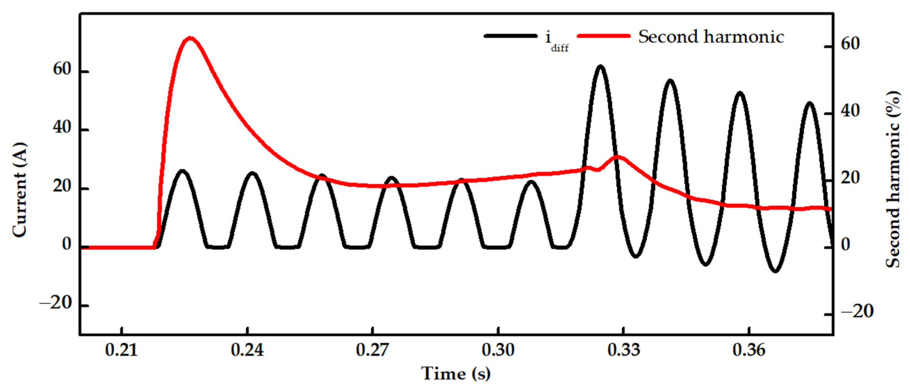
2.1. Overview of Magnetizing Inrush Current and Second Harmonic Ratio

An inrush current is the high current drawn by a transformer when it is initially energized. It is caused by an abrupt change in magnetic flux within the transformer core and is proportional to the current flowing through the primary winding. Figure 1 illustrates a differential current and the ratio of the second harmonic. As mentioned in the Introduction, a common approach to differential protection in power transformers involves second harmonic-based blocking to prevent unnecessary tripping. Due to the substantial ratio of the second harmonic during transformer energization, it can be effectively used to distinguish an inrush current from internal faults. However, as shown in Figure 1, a second harmonic may also be generated during internal faults due to a decaying DC component from faults. At the moment of transformer energization, the ratio of the second harmonic rapidly increases to approximately 60%. Consequently, the harmonic-blocking method blocks the operation of the differential relay in this scenario, leading to potential damage to the power transformer.
DW is a technique applied in power system protection for fault detection, direction estimation, time-series forecasting, and fault classification. It yields promising results at every instant when there is a significant fluctuation in the waveform. The results based on the data window from [14,15,16] are noticeable when dealing with abnormal conditions. Inspired by this concept, we develop a DW which was originally proposed in [31] to detect power swings on a transmission line. Considering the measured differential current i d i f f = { x 1 ,   ,     x k } , where k is the last index of the measured differential current, the equation derived from a set of DWs on the measured differential current is expressed in (1) as follows:
Set   of   DWs = x 1 x 2 x m - 1 x m x 2 x 3 x m x m + 1 x k - m + 1 x k - m + 2 x k - 1 x k

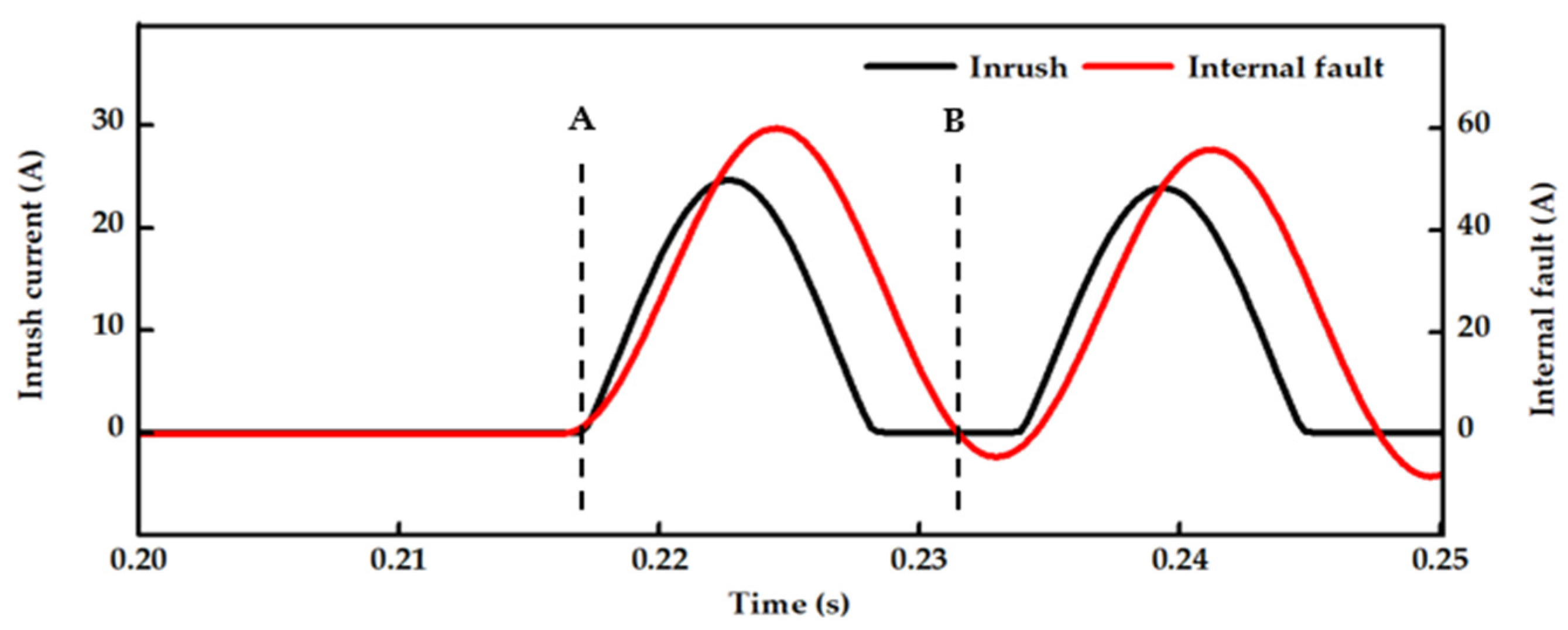
2.2. Data Window of Inrush Current and Internal Faults

The waveform in the DW, as described in (1), forms an abundance of distinctive waveform characteristics at each sample point. These characteristics enable DNN to capture the unique features distinguishing inrush currents from internal faults. Figure 2 illustrates a region of instantaneous differential currents under a DW with a length of one cycle. This figure clearly demonstrates the DW under conditions of an inrush current and an internal fault. Prior to a sudden spike in the current due to transformer energization, every value in the DW is zero in each sample. Upon closing the circuit breaker, there is a sudden change in the magnetic flux, leading to a significant increase in the differential current. Similarly, an internal fault also manifests a sudden change at the initial point in the differential current, posing a challenge for conventional methods to discriminate internal faults from inrush currents when both conditions coincide. As illustrated in Figure 2, every value in the DW before point A is zero, designating this region as the normal condition (state 0). Upon reaching point A, the value of the last index of the DW becomes positive, indicating the occurrence of a transient state (state 1). If an internal fault and an inrush current occur simultaneously at this point, it becomes challenging to determine each disturbance. Therefore, no action will be taken during this transition. At point B, an internal fault exhibits different characteristics from an inrush current. For internal faults, the value becomes zero for a fault inception angle of 0° or negative for a fault inception angle of 90°. When this behavior is detected, the algorithm promptly changes to state 3 (internal fault); otherwise, it identifies an inrush current (state 2). The sampling delay between points A and B is less than one cycle, specifically 58 samples, considering that one cycle corresponds to 64 samples. The reason for this delay is to achieve a clear discrimination between inrush currents and internal faults at a fault inception angle of 0°.
Therefore, it is apparent that this difference can be effectively used as an important feature to distinguish internal faults from inrush currents and to create learning labels for DNNs, which will be explained later in the following section.

2.3. Dataset Acquisition for Training and Testing Procedure

A thorough analysis is necessary to achieve high accuracy and generalization in the discrimination model for inrush currents and internal faults using a DNN-based method. The generation of sufficient datasets for training DNNs is crucial for accurately discriminating between the mentioned abnormalities. To obtain diverse datasets for inrush currents, extensive simulations are required for subsequent analysis. The training dataset considers influencing parameters in inrush conditions, such as the residual flux in the power transformer, the switching angle, and the polarity of the residual flux. The inrush current magnitude is at its maximum when the transformer switches on at 0°. Moreover, the polarity of the residual flux significantly impacts the magnitude of the inrush current. The influencing parameters for inrush currents and internal faults are listed in Table 2. The datasets for inrush currents accumulated 170 inrush conditions, corresponding to 228,140 datasets available for training and testing. The influencing parameters for the internal faults are given in Table 2. The datasets for the internal faults accumulated 90 cases of a–g faults, corresponding to 111,870 datasets available for training and testing. The inrush current and internal faults are randomly partitioned into training and testing datasets with an 80% to 20% ratio, respectively.

2.4. Dataset Preprocessing for Training

The preprocessing stage for training DNNs is the most crucial part, determining the outcome of the trained model. It serves as a platform for DNNs to quickly comprehend the problem statement and the approach to achieving the expected outcomes in the final stage. As the magnitude of an inrush current varies depending on the influencing parameters listed in Table 2, it is challenging to determine a specific threshold for the correct label for DNNs. Therefore, normalization is introduced to address the problem of numerical instability and uncertain thresholds caused by the varying magnitudes of an inrush current. The derived equation for normalizing the training input is given in (2) as follows.
x norm = x i x max
where xmax is the maximum value captured in the measured differential current. Normalizing the input dataset scales the training input within the range of [–1, 1]. Additionally, this process enhances the robustness and capability of the proposed DNN, making it applicable to datasets from different systems. Once a set of DWs are formed, as described in (1), and the label for each condition is defined, as described in Section 2.2, we convert the multi-class region into a binary form using one-hot encoding, as shown in Table 3.

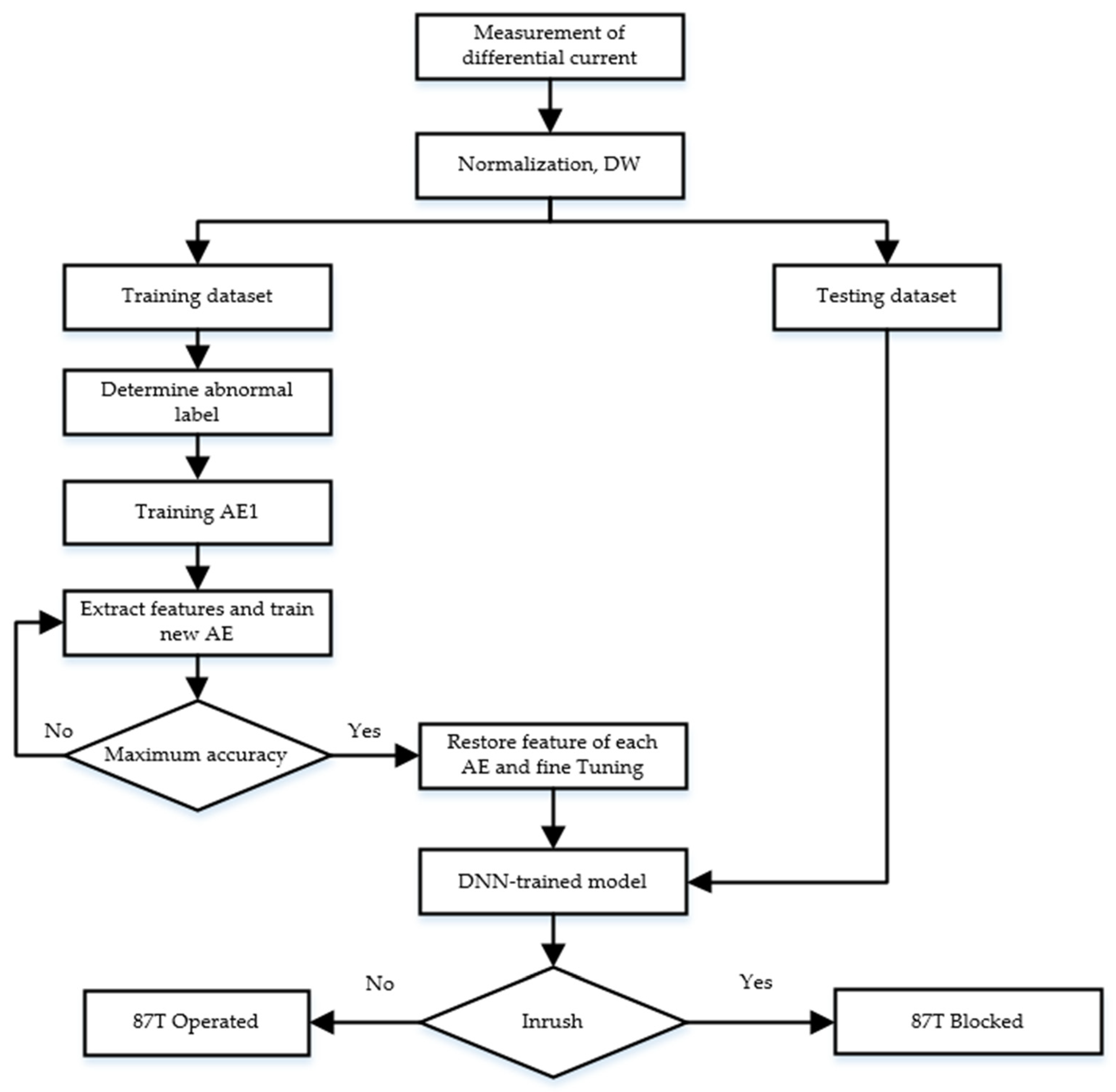
3. Deep Neural Network (DNN)-Based Discrimination

DNNs have undergone continuous evolution, demonstrating a strong capability to address challenging problems in recent years, particularly in cases where conventional methods struggle with nonlinear issues. This section introduces the concepts and strategies implemented to discriminate inrush currents and internal faults. To enhance the structure of DNNs, the proposed discrimination scheme adopts unsupervised pre-training using stacked autoencoders and supervised fine-tuning. The details of benchmark models are demonstrated well in [32,33].

3.1. Principle of Autoencoders

An autoencoder is the basic component of an SAE learning in an unsupervised way, typically containing an encoder and a decoder. In a simple autoencoder, the input xRn (x1, x2, …, xn) is included in the training dataset. The input is then encoded to a low dimension and restored to its original dimension in the decoding part. The training uses backpropagation to minimize the reconstruction error of the input features. Once the training converges, the transformed features (f1, f2, …, fn) are saved and used to train other autoencoders. The encoder employs a deterministic mapping function to map input x to the hidden layer f. The encoding process is given as follows in (3), where W1 and b1 are the weight and bias of the encoding parts.
f = S ( W 1 x + b 1 )
The decoder reconstructs the hidden layer representation (f) to obtain the output ( x ^ ), as shown in (4), where W2 and b2 are the weight and bias of the decoding parts. S denotes the activation function for training the AE, and ReLU is used for both the encoder and decoder.
x ^ = S W 2 f + b 2
The parameters of the AE are optimized to minimize the reconstruction error, as shown in (5).
L AE x , x ^ = 1 N n = 1 N x - x ^ θ f θ x ^

3.2. Framework of Stacked Autoencoder

An SAE is a neural network consisting of multiple layers of AEs, where the features of each AE are stacked and fed as inputs to the successive AE. The first AE is trained in a bottleneck fashion with the initial weight and bias (w1 and b1). The input is compressed into a low-dimensional feature through the encoding function and then restored back to its original dimension in the decoding layer. After removing the decoding layer ( x ^ ) in the first AE, a new hidden layer ( h 2 ) and an output ( h ^ 1 ) are stacked onto the first AE. Using a similar process, many AEs are successively stacked together to form a deeper network structure. This process is commonly known as pre-training because it adopts a greedy-layer training method. Finally, an output layer is trained with the given label (binary form of the abnormality) to discriminate between inrush currents and internal faults. All optimal SAE weights and biases (wi and bi, where i = 1, 2, , n), which are obtained during the pre-training process, are fine-tuned using the backpropagation algorithm to achieve significant improvements in discrimination ability. The construction process of a three-layer SAE is depicted in Figure 3.

3.3. Fine-Tuning and SoftMax Classifier
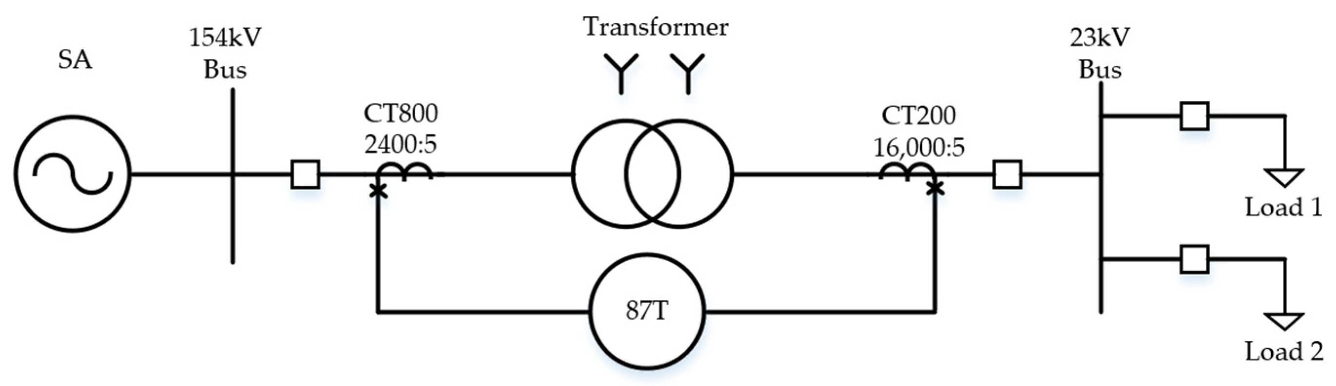
The pre-trained model from the SAE can be further optimized by using parameters from all encoding layers during the pre-training phase with the backpropagation algorithm to minimize errors. Using the weights (Wi) and biases (bi) from an SAE as initial values for fine-tuning enables the deeper network to generalize more effectively to other inrush variations produced by power transformers. We assign labels and extract features from the SAE to the classifier layer for the precise discrimination between normal conditions, inrush currents, and internal faults. Consequently, the classification outputs exhibit minimal errors, resulting in high accuracy.
A SoftMax classifier is employed in the classifier layer to discriminate among the four classes listed in Table 3. It estimates the posterior probabilities of each class in the range of [0,1], and the hypothesis is calculated as follows.
h θ ( x i ) = p y i = 1 x i , θ p y i = 2 x i , θ p y i = k x i , θ = 1 l = 1 k e θ l T x i e θ 1 T x i e θ 2 T x i e θ k T x i
where yi is the stochastic variable of the output class corresponding to input dataset xi, and j represents the output class, encompassing four conditions: normal, transient, inrush, and internal fault. θ = ( θ 1 T , θ 2 T , , θ k T ) T denotes the parameter set of the model. Consequently, the output of the SoftMax classifier is given in a 4-dimensional vector containing four possible classes. The maximum probability of each class is determined as follows.
Class x i = argmax j = 1 , , k p ( y i = j x i , θ )
Likewise, the SoftMax classifier converges to the global minimum by iteratively optimizing the cost function in (8) using categorical cross entropy.
L = 1 N   i = 1 m j = 1 k S y i = j log e θ j T x i l = 1 k e θ l T x i + σ 2 i = 1 k j = 1 N θ ij 2
where y i is the ith scalar value from the SoftMax output in (7), S represents the indicator function, σ is included in the cost function to penalize large values of the parameters, and L is strictly convex.
A flowchart of the proposed DNN is depicted in Figure 4.

4. Simulation Model

This section will highlight the simulation setup used to generate datasets for verifying the proposed DNN.

4.1. PSCAD/EMTDC Model

The effectiveness of the proposed technique was verified using a typical Korean 154 kV distribution substation. A simulation model of a 154/23 kV distribution system with 40 MVA power transformer and a Y-Y configuration was built in PSCAD/EMTDC, as illustrated in Figure 5. The sampling frequency was set to 3840 Hz or 64 samples per cycle in 60 Hz systems. The source was defined by the specific parameters listed in Table 4. In this study, only winding-ground faults were considered for evaluation, with variations in the fault inception angles and percentages of the winding faults. The winding faults were simulated by varying the fault location in the transformer, winding between 10% and 90%, in steps of 20%, from the winding terminal on the primary side of the transformer. The fault inception angle of the internal faults varied from 0° to 90°, in steps of 15°, with reference to the phase-A current. During the generation of magnetizing inrush currents, a residual flux was considered in the range of −80% to 80%, in steps of 10%, and different switching instances were considered between 0° and 90°.

4.2. Deep Neural Network Model

Tensorflow is one of the most common deep learning platforms developed by Google. It offers a high-level API to optimize neural network models and the training procedure of the proposed DNN model. Therefore, the Tensorflow library is adopted in this paper to construct the network model and to train it to discriminate between inrush currents and internal faults.
In both the unsupervised and supervised learning modes, a categorical cross-entropy loss was employed to quantify the error between the network output and the reference output. The Adam optimizer was used to build the network for gradient backpropagation and parameter updates in every epoch. A decaying learning rate was applied to enhance convergence performance and to expedite the training process, preventing issues related to overfitting. It was initially set at 8   ×   10 3 and then exponentially decreased with each iteration. The structure of the DNN and the training parameters for each AE are given in Table 5.

5. Simulation Results

In this section, the efficiency of the proposed DNN is verified and compared to the unidirectional index method in [28], the conventional harmonic-blocking scheme [34], and the Extended Kalman filter in [35]. Graphical illustration and evaluation metrics make it abundantly evident that the proposed method is effective against inrush currents and internal faults. In Figure 6, Figure 7, Figure 8, Figure 9, Figure 10 and Figure 11, DNN, UNI, and HAR denote the proposed DNN method, the unidirectional index in [28], and the second-harmonic-blocking approach [34], respectively. The Extended Kalman filter in [35] is used for comparison when internal faults are present, because EKF only detects the instance of internal faults. It is generally known that protection relays in power system protections operate after one cycle. Therefore, the evaluation of the proposed DNN and alternative methods will be discussed based on the 58th (=N–6) and 61st (=N–3) samples from each abnormality.

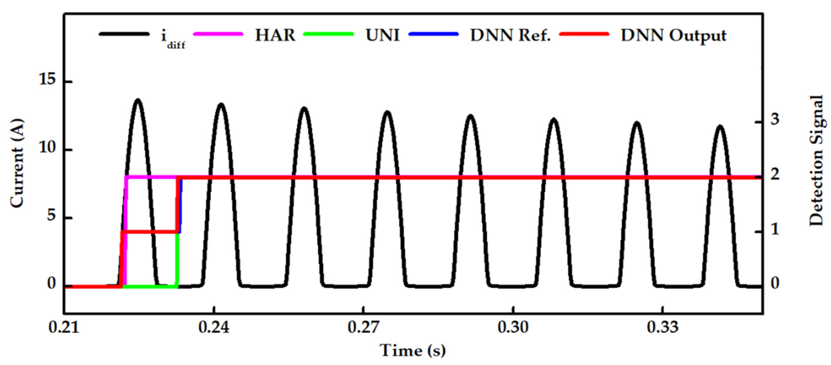
5.1. Case Study 1: Inrush Current at a Switching Angle of 0°

Magnetizing inrush currents are generated due to the remanent magnetism and no-load closing of a power transformer. The closing instance significantly influences the waveform characteristics of the inrush current, while its remanent magnetism mainly affects its amplitude.
Transformer energization cases without and with residual flux are studied in this section. Figure 6 shows the results when a transformer without residual flux was energized at a switching instance of 0°, corresponding to 0.2 s. As the ratio of the second harmonic sharply increased at the closing instance, the HAR was theoretically effective in quickly detecting the inrush current. The UNI detected the inrush current after a timing delay due to the data window, while the proposed DNN detected it at 0.231 s, with a slightly quicker response than the DNN reference. Based on Figure 6, it is evident that the proposed DNN presented a promising output in noticing the inrush current after sample N–6, which was comparable to the HAR and UNI.
The performance of the proposed DNN was also evaluated considering transformer energization with the maximum residual flux, which was approximately 80%. The amount of residual flux heavily influenced the magnitude of the inrush current; as a result, the magnitude of the inrush current nearly doubled in this case, as demonstrated in Figure 7. It can be seen that the HAR yielded the best output among the three approaches in this case. Considering a time delay, the UNI responded to the inrush current at 0.234 s, whereas the DNN demonstrated a quicker detection instance than the UNI. For instance, the DNN detected inrush currents faster (one sample) and more accurately than the UNI.

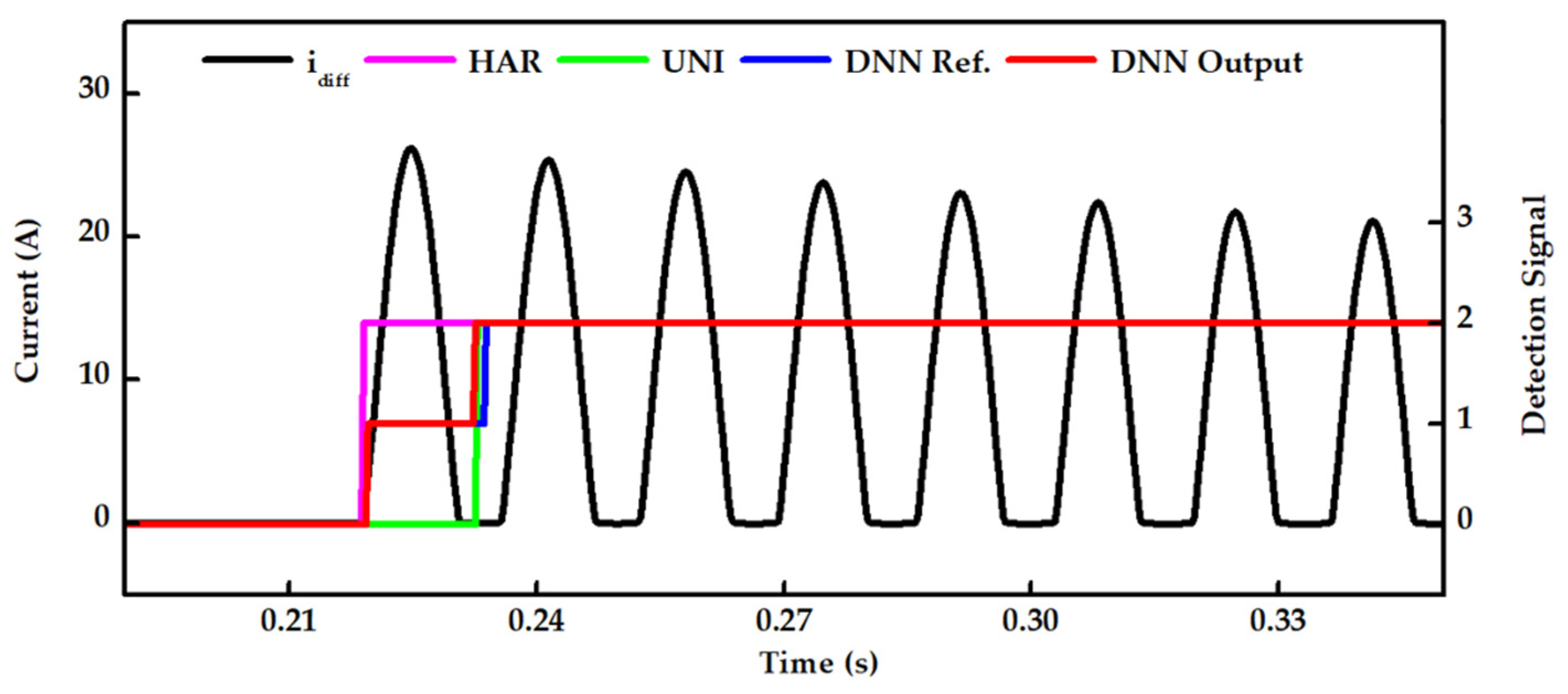
5.2. Case Study 2: Inrush Current at a Switching Angle of 90°

Switching a power transformer at 90° with no residual flux does not impact the operation of conventional differential relays and produces the least inrush currents. However, the maximum flux in the power transformer strongly influences the nonlinear nature of the magnetizing inrush current, as depicted in Figure 8. The magnitude of the inrush current in this case is similar to that depicted in Figure 6. Therefore, the detection of the inrush current was examined at the maximum switching angle and with residual flux. As displayed in Figure 8, the HAR showed the most promising outcome, as it reacted to the first instance of an inrush current due to the presence of the second harmonic ratio. Due to the data window used in the UNI and DNN, their detections showed a timing delay of less than 1 cycle. In particularly, the DNN yielded a more promising outcome than the UNI, as it was 8 samples quicker. That is, the DNN faultlessly detected the inrush current after the 61st (=N–3) sample from the switching instance.

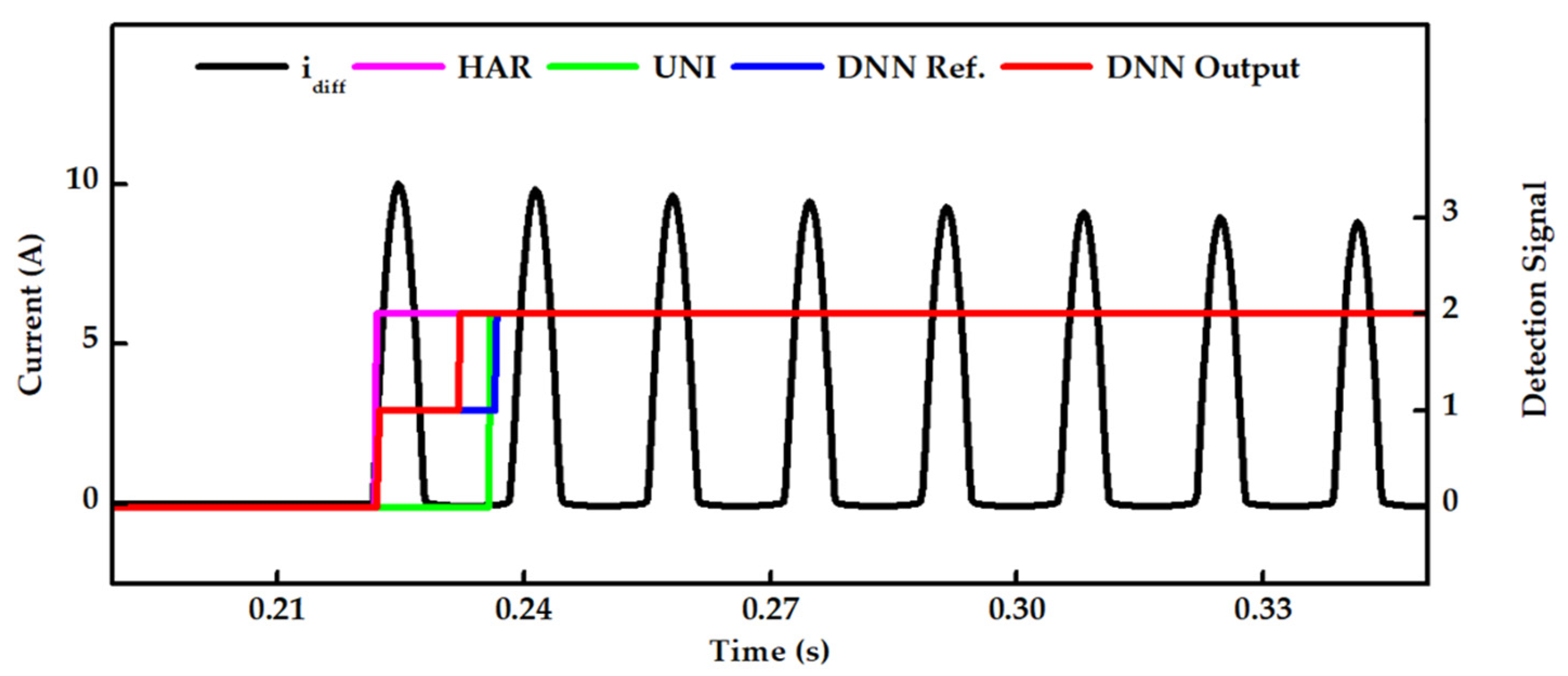
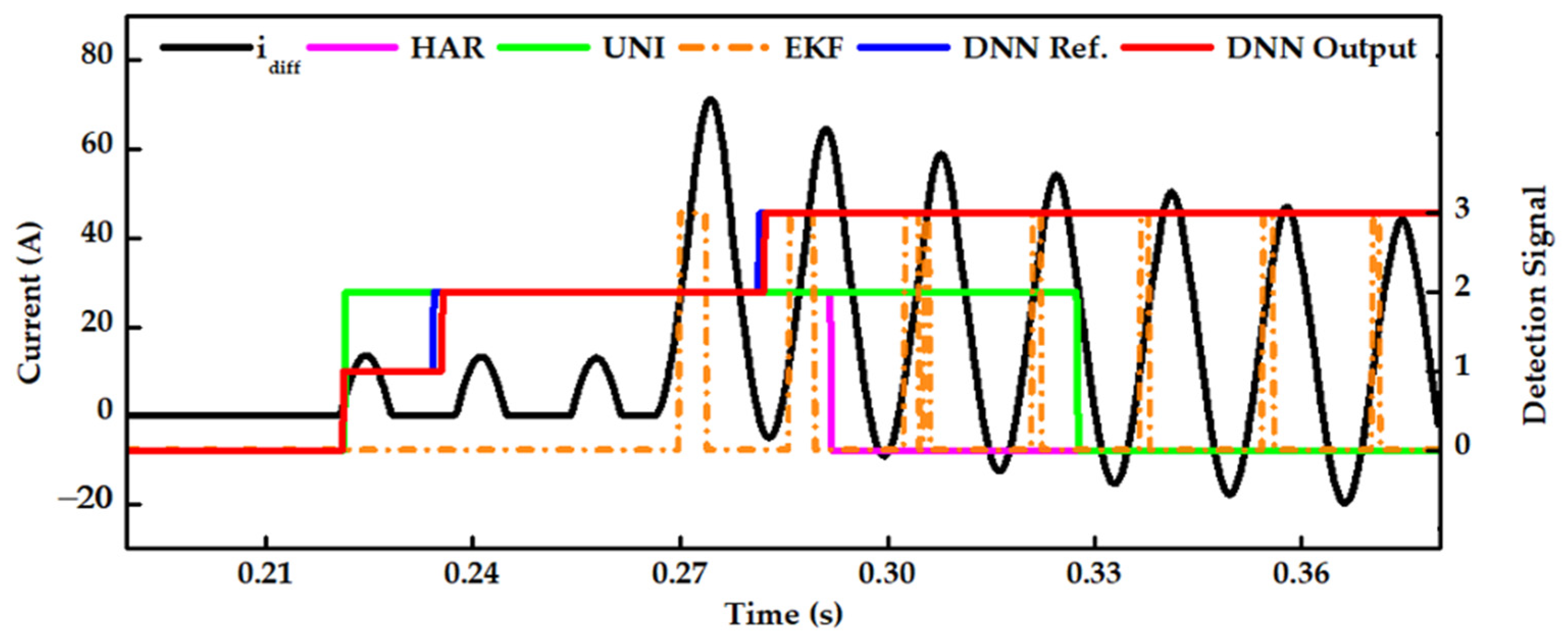
5.3. Case Study 3: Energization of a Power Transformer in the Presence of an Internal Fault

Energizing a power transformer in the presence of an internal fault is a challenging task for conventional protections, as the ratio of the second harmonic may cause the differential relay to be blocked, potentially leading to severe damage to the power transformer. In this case, we consider a–g faults for internal faults. Figure 9 shows the results of internal-fault detection when a power transformer was energized in the presence of an internal fault. The evaluation was conducted in two different scenarios at fault inception angles of 0° and 90°.
As shown in Figure 9a, the conventional HAR method detected the inrush current rather than the internal fault due to the presence of the second harmonic in the decaying DC component generated during the internal fault. Consequently, it prevented the internal fault from being detected, resulting in the blocking of the differential relay operation. In contrast, the UNI detected the differential current as an inrush current instead of an internal fault. The EKF could not discriminate the internal fault from the inrush current. Moreover, the inaccuracy increased as the EKF estimated differential currents with noise. Unlike the conventional HAR and UNI methods, the proposed DNN demonstrated an impressive success rate in discriminating the internal fault from the inrush current after the 58th sample from the abnormality. In this manner, the DNN exhibited high sensitivity to internal faults, even though the HAR and UNI failed to detect them. As shown in Figure 9a, for the fault inception angle of 90°, the HAR failed to detect the internal fault for several cycles, highlighting a drawback of using HARs in modern transformers. In contrast, the proposed DNN successfully detected the internal fault, starting from just one sample later than the DNN reference. Similarly, as illustrated in Figure 9b, the DNN exhibited a promising output in discriminating between inrush currents and internal faults at a fault inception angle of 0°.

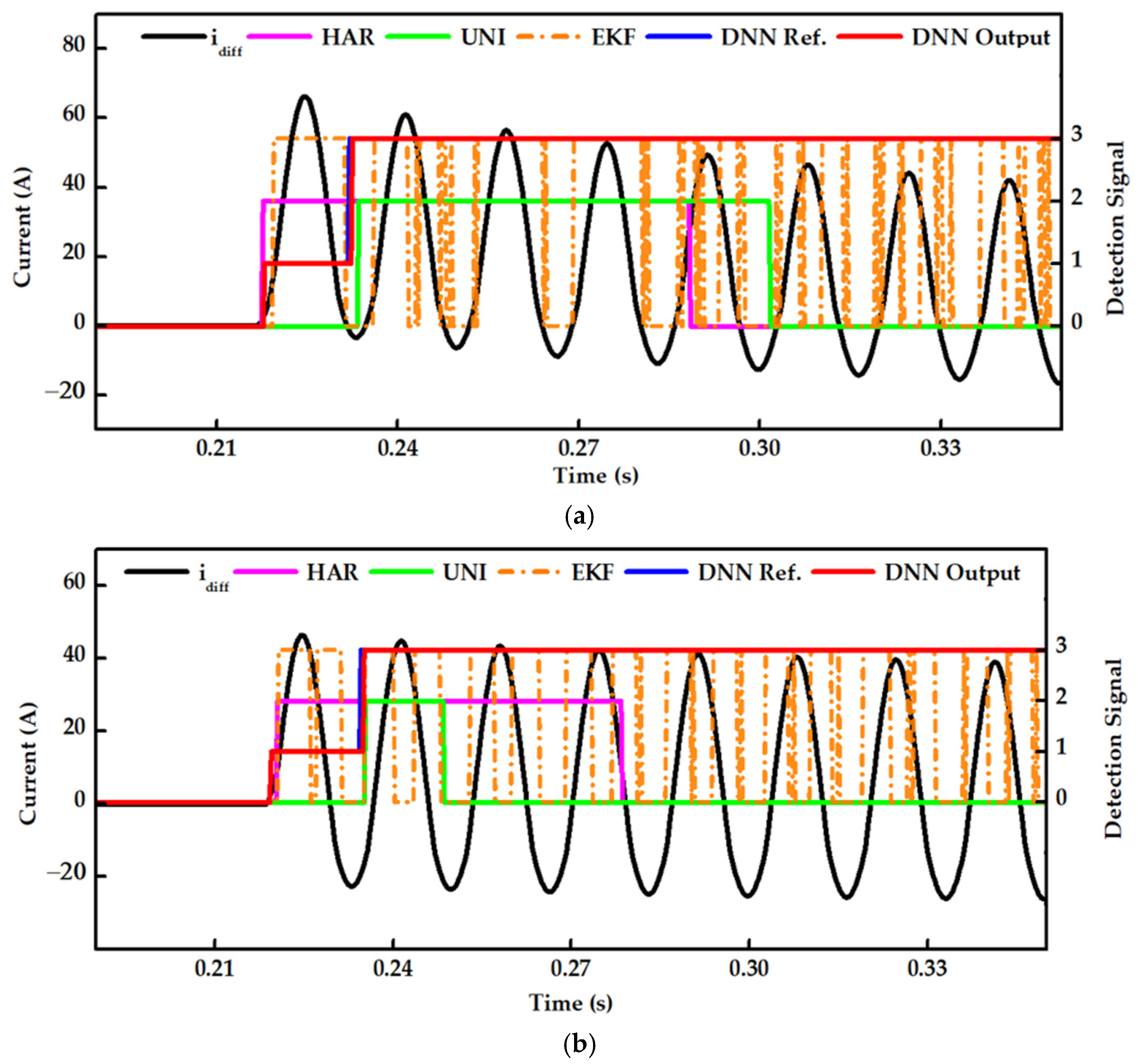
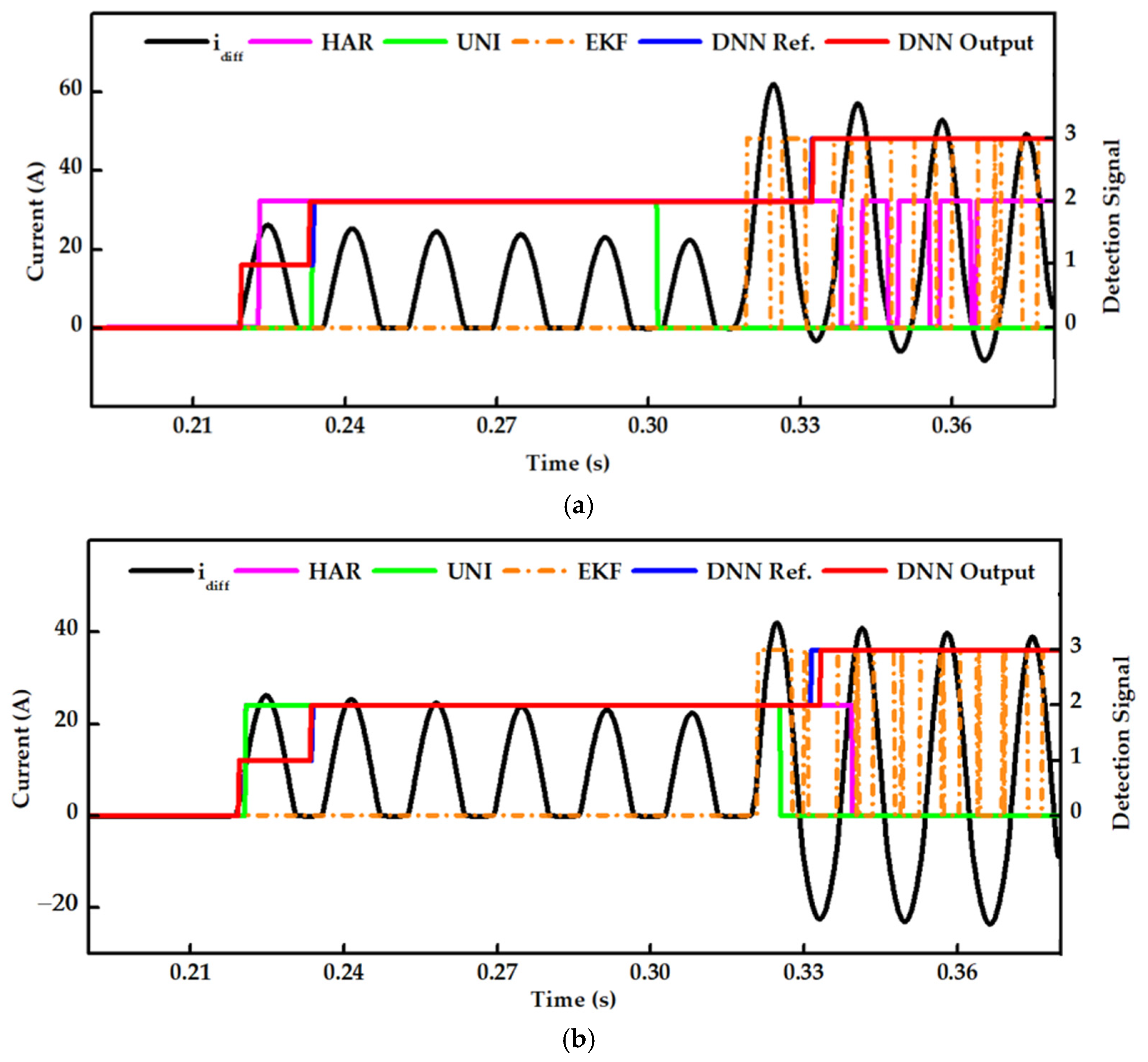
5.4. Case Study 4: Phase-A-to-Ground Internal Faults Occurring during the Energization of a Power Transformer

The proposed DNN was validated during an internal fault occurring a few cycles after the switching of a power transformer. The harmonic-blocking scheme blocked the operation of the differential relay due to the large ratio of the second harmonic at the onset of an internal fault. This could lead to damage to the power transformer and should be avoided.
A power transformer was switched on for energization at 0.22 s, and the internal fault occurred at 0.32 s, as demonstrated in Figure 10. With the interference of the internal fault, the HAR showed unsatisfactory results as soon as the internal fault occurred. The HAR blocked the differential relay from operating for around two cycles, which could negatively affect the power transformer. The UNI showed the worst results among the three methods, as it did not respond to the internal fault in this case. UNI is only applicable when there is a direction of the waveform on the positive or negative side, as its bidirectional index makes it vulnerable to internal faults. The proposed DNN could detect the internal fault with a time delay of less than one cycle from the fault inception. The evaluation was performed on internal faults at fault inception angles of 0° and 90°, as illustrated in Figure 10a,b, respectively. The results show that the proposed DNN can detect internal faults after a time delay of less than one cycle, regardless of the fault inception angle.
The influence of external faults on the proposed DNN can be ignored since the differential current will be zero during an external fault. Therefore, the DNN bypasses external faults and allows relevant protection schemes outside the protection zone to operate based on disturbance criteria.

5.5. Case Study 5: Phase-B–C-to-Ground Internal Faults Occurring during the Energization of a Power Transformer

To demonstrate the capability of the proposed DNN across different fault types, phase-B–C-to-ground internal faults are considered in this case. Figure 11 presents a case of a phase-B–C-to-ground internal fault at a different time node considering a fault inception angle of 0°. The internal fault depicted in Figure 11 occurs three cycles after the inrush current takes place. Similar to Case Study 4, the UNI successfully detects the instance of the inrush current; however, the operation of the differential protection is continually blocked for almost one cycle after an internal fault occurs. On the other hand, the UNI proves to be effective in responding to the inrush current but fails to detect the internal fault for several cycles. The EKF exhibits low sensitivity to the internal fault because the estimated current from the EKF produces noise. Unlike these three methods, the proposed DNN demonstrates an accurate and reliable output in discriminating internal faults with a given time delay.

6. Discussion on the Performance Evaluation Metrics

To effectively evaluate the performance of the proposed DNN, three indicators were selected as evaluation metrics: accuracy, sensitivity, and precision. Traditionally, accuracy alone is insufficient to determine whether the proposed DNN yields a promising outcome. To visualize the stability of the proposed DNN method, a confusion matrix was used, summarizing the classification performance and providing a visual representation of the actual and predicted classes. The evaluation matrix was assessed using the following four performance indices: TP (true positive), TN (true negative), FP (false positive), and FN (false negative).
ACC = TP + TF ( TP + TF + FP + FN )
SEN = TP ( TP + FN )
PRE = TP ( TP + FP )
Conventionally, accuracy (ACC) shows the authenticity of a detection method, defining the correct detections over the total numbers of detections, including correct and false ones. Sensitivity (SEN) measures the proportion of inrush and internal faults that were correctly identified among the actual labels. It is a crucial metric in discrimination, because it influences the decision to allow the differential relay to operate when an internal fault occurs during inrush currents. A high percentage of SENs is essential to determine the stability of the proposed DNN. Precision (PRE) is another important metric required to affirm the correctness of the proposed DNN. For instance, it demonstrates the capability of the proposed DNN to isolate internal faults from inrush currents when both abnormalities occur simultaneously. In other words, it demonstrates the ability of internal-fault detection without mistakenly identifying it as an inrush current. A comparative analysis was conducted, and the evaluation metrics are presented in Table 6. The effectiveness of these metrics was assessed at the 58th and 61st samples from the beginning of each abnormality.
In cases where a power transformer is energized in the presence of an internal fault, the aim is to avoid a situation where the DNN mistakenly detects it as an inrush current instead of an internal fault. Therefore, the DNN places emphasis on minimizing FNs; otherwise, incorrect detections could lead to damage to the power transformer. The DNN detects the internal fault at the 61st sample, which is three samples later than the DNN reference; therefore, the DNN experienced three FNs in this case. The performance of the proposed DNN and the other methods was evaluated at the 58th (=N–6) and 61st (=N–3) samples from the beginning of each abnormality. It is noted that detection with a time delay of 61 samples will be sufficient to protect the power transformer, as the protection decision will be made after 64 samples.
According to the percentages presented in Table 6, it is evident that all four methods correctly classified the normal condition from the other two abnormalities without any defects. For inrush conditions, the HAR was undoubtedly proven to be effective, achieving the highest metrics at the 58th and 61st samples. The UNI exhibited good performance in detecting inrush currents, with ACC, SEN, and PRE values of 99.852%, 93.814%, and 95.724%, respectively. The UNI is unable to achieve the highest metric at the 61st sample, as inrush currents were detected at the 62nd sample in some cases. On the other hand, the UNI performed poorly when experiencing internal faults, as it was more sensitive to inrush currents. The DNN displayed a promising evaluation index in detecting the inrush duration at the 58th sample, yielding the highest ACC, SEN, and PRE values of 99.526%, 100%, and 99.523%, respectively. At the 61st sample, the DNN could accurately classify between inrush currents and internal faults, achieving 100% for all three metrics.
Furthermore, the DNN demonstrates excellent performance in detecting internal faults during inrush currents. The evaluation index produced by the DNN outperformed the other three methods at sample N–6, achieving ACC, SEN, and PRE values of 99.651%, 99.642%, and 100%, respectively. At sample N–3, the DNN achieved the best metrics (ACC, SEN, and PRE), all at 100%. In contrast, the EKF showed worse performance compared to the DNN in this study, as it mis-detected the internal faults due to the difference between the measured and estimated currents. Moreover, EKF is inapplicable to other systems and significantly relies on a threshold to detect internal faults, presenting a less favorable discrimination between inrush currents and internal faults. At sample N–3, it yielded ACC, SEN, and PRE values of 92.136%, 71.369%, and 70.364%, respectively.

7. Conclusions

This paper proposes a DNN-based method to discriminate between inrush currents and internal faults utilizing a data window. The effectiveness of the proposed DNN was assessed through numerical simulations, including inrush currents, internal faults, and cases where the inrush current coincided with internal faults. Despite achieving less accurate results during inrush currents, compared to HAR, DNN performs better in detecting internal faults, even during inrush conditions. Based on graphical illustrations and evaluation metrics, DNN successfully detects internal faults during inrush conditions, enabling the differential relay to operate without delay, regardless of the fault inception angle and residual flux. As DNN does not require a specific threshold to perform the discrimination, it can be applied to different systems to discriminate inrush currents from internal faults.
HAR and UNI are insufficient to deal with both inrush currents and internal faults occurring together. Although EKF can detect internal faults, the effectiveness of EKF is reduced in other systems due to an indecisive threshold. The deficiencies of the prevailing methods, such as reliance on physical parameters and indecisive predefined thresholds, decrease their reliability and generality. In comparison to prevailing methods (HAR, UNI, and EKF), the proposed DNN shows promising results from sample N–3, achieving accuracy, sensitivity, and precision values of 100%. It is considered to be one of the promising solutions for discriminating between inrush currents and internal faults. The proposed DNN may produce errors in the presence of CT saturation. Our future work involves developing a discrimination model for the main and backup protections that considers CT saturation and implementing the proposed DNN to discriminate internal faults from inrush currents in real time. The experiment will be based on hardware implementation, which consists of RTDS and EVM boards.

Author Contributions

Conceptualization, S.K. and S.-R.N.; methodology, S.K., G.-W.S. and S.-R.N.; supervision, S.-R.N.; validation, S.K. and G.-W.S.; writing—original draft, S.K. and S.-R.N.; writing—review and editing, S.K., G.-W.S. and S.-R.N. All authors have read and agreed to the published version of the manuscript.

Funding

This research was supported in part by Korea Electric Power Corporation (Grant number: R23XO05-07). This research was also supported in part by the Korea Research Foundation, with funding from the government (Ministry of Education) in 2021 (No. NRF-2021R1F1A1061798).

Data Availability Statement

Data are contained within the article.

Conflicts of Interest

The authors declare no conflicts of interest.

References

  1. Gopika, R.; Deepa, S. Study on Power Transformer Inrush Current. IOSR J. Electr. Electron. Eng. 2017, 2, 59–63. [Google Scholar]
  2. Baoming, G.; Dealmeida, A.; Qionglin, Z.; Xiangheng, W. An Equivalent Instantaneous Inductance-Based Technique for Discrimination between Inrush Current and Internal Faults in Power Transformers. IEEE Trans. Power Deliv. 2005, 20, 2473–2482. [Google Scholar] [CrossRef]
  3. Guzman, A.; Fischer, N.; Labuschagne, C. Improvements in transformer protection and control. In Proceedings of the 2009 62nd Annual Conference for Protective Relay Engineers, College Station, TX, USA, 30 March–2 April 2009; pp. 563–579. [Google Scholar]
  4. Hamilton, R. Analysis of transformer inrush current and comparison of harmonic restraint methods in transformer protection. IEEE Trans. Ind. Appl. 2013, 49, 1890–1899. [Google Scholar] [CrossRef]
  5. Zhang, L.; Wu, Q.; Ji, T.; Zhang, A. Identification of inrush currents in power transformers based on higher-order statistics. Electr. Power Syst. Res. 2017, 146, 161–169. [Google Scholar] [CrossRef]
  6. Mo, C.; Ji, T.; Zhang, L.; Wu, Q. Equivalent statistics based inrush identification method for differential protection of power transformer. Electr. Power Syst. Res. 2022, 203, 107664. [Google Scholar] [CrossRef]
  7. Hodder, S.; Kasztenny, B.; Fischer, N.; Xia, Y. Low second-harmonic content in transformer inrush currents—Analysis and practical solutions for protection security. In Proceedings of the 2014 67th Annual Conference for Protective Relay Engineers, College Station, TX, USA, 31 March–3 April 2014; pp. 705–722. [Google Scholar]
  8. Lu, Z.; Tang, W.H.; Ji, T.Y.; Wu, Q.H. A Morphological Scheme for Inrush Identification in Transformer Protection. IEEE Trans. Power Deliv. 2009, 24, 560–568. [Google Scholar] [CrossRef]
  9. Vazquez, E.; Mijares, I.I.; Chacon, O.L.; Conde, A. Transformer differential protection using principal component analysis. IEEE Trans. Power Deliv. 2008, 23, 67–72. [Google Scholar] [CrossRef]
  10. Afrasiabi, S.; Afrasiabi, M.; Parang, B.; Mohammadi, M.; Samet, H.; Dragicevic, T. Fast GRNN-Based Method for Distinguishing Inrush Currents in Power Transformers. IEEE Trans. Ind. Electron. 2021, 69, 8501–8512. [Google Scholar] [CrossRef]
  11. Afrasiabi, S.; Afrasiabi, M.; Parang, B.; Mohammadi, M. Integration of Accelerated Deep Neural Network into Power Transformer Differential Protection. IEEE Trans. Ind. Inform. 2019, 16, 865–876. [Google Scholar] [CrossRef]
  12. Samet, H.; Ghanbari, T.; Ahmadi, M. An Auto-Correlation Function Based Technique for Discrimination of Internal Fault and Magnetizing Inrush Current in Power Transformers. Electr. Power Compon. Syst. 2015, 43, 399–411. [Google Scholar] [CrossRef]
  13. Mao, P.; Aggarwal, R. A novel approach to the classification of the transient phenomena in power transformers using combined wavelet transform and neural network. IEEE Trans. Power Deliv. 2001, 16, 654–660. [Google Scholar] [CrossRef]
  14. Key, S.; Ko, C.-S.; Song, K.-J.; Nam, S.-R. Fast Detection of Current Transformer Saturation Using Stacked Denoising Autoencoders. Energies 2023, 16, 1528. [Google Scholar] [CrossRef]
  15. Key, S.; Kang, S.-H.; Lee, N.-H.; Nam, S.-R. Bayesian Deep Neural Network to Compensate for Current Transformer Saturation. IEEE Access 2021, 9, 154731–154739. [Google Scholar] [CrossRef]
  16. Sok, V.; Lee, S.-W.; Kang, S.-H.; Nam, S.-R. Deep Neural Network-Based Removal of a Decaying DC Offset in Less Than One Cycle for Digital Relaying. Energies 2022, 15, 2644. [Google Scholar] [CrossRef]
  17. Silva, K.; Souza, B.; Brito, N. Fault Detection and Classification in Transmission Lines Based on Wavelet Transform and ANN. IEEE Trans. Power Deliv. 2006, 21, 2058–2063. [Google Scholar] [CrossRef]
  18. Costa, F.B.; de Souza, B.A.; Brito, N.S.D. Detection and Classification of Transient Disturbances in Power Systems. IEEJ Trans. Power Energy 2010, 130, 910–916. [Google Scholar] [CrossRef]
  19. Gaouda, A.M.; Salama, M.M.A. DSP Wavelet-Based Tool for Monitoring Transformer Inrush Currents and Internal Faults. IEEE Trans. Power Deliv. 2010, 25, 1258–1267. [Google Scholar] [CrossRef]
  20. Saleh, S.A.; Scaplen, B.; Rahman, M.A. A new implementation method of wavelet-packet-transform differential protection for power transformers. IEEE Trans. Ind. Appl. 2011, 47, 1003–1012. [Google Scholar] [CrossRef]
  21. Costa, F.B. Fault-induced transient detection based on real-time analysis of the wavelet coefficient energy. IEEE Trans. Power Deliv. 2014, 29, 140–153. [Google Scholar] [CrossRef]
  22. Medeiros, R.P.; Costa, F.B.; Silva, K.M. Power Transformer Differential Protection Using the Boundary Discrete Wavelet Transform. IEEE Trans. Power Deliv. 2015, 31, 2083–2095. [Google Scholar] [CrossRef]
  23. Medeiros, R.P.; Costa, F.B. A Wavelet-Based Transformer Differential Protection with Differential Current Transformer Saturation and Cross-Country Fault Detection. IEEE Trans. Power Deliv. 2017, 33, 789–799. [Google Scholar] [CrossRef]
  24. Medeiros, R.P.; Costa, F.B. A wavelet-based transformer differential protection: Internal fault detection during inrush conditions. IEEE Trans. Power Deliv. 2018, 33, 2965–2977. [Google Scholar] [CrossRef]
  25. Ruhan, Z.; Mansor, N.N.B.; Illias, H.A. Identification of Inrush Current Using a GSA-BP Network. Energies 2023, 16, 2340. [Google Scholar] [CrossRef]
  26. Peng, F.; Gao, H.; Huang, J.; Guo, Y.; Liu, Y.; Zhang, Y. Power Differential Protection for Transformer Based on Fault Component Network. IEEE Trans. Power Deliv. 2023, 38, 2464–2477. [Google Scholar] [CrossRef]
  27. Ali, E.; Helal, A.; Desouki, H.; Shebl, K.; Abdelkader, S.; Malik, O. Power transformer differential protection using current and voltage ratios. Electr. Power Syst. Res. 2017, 154, 140–150. [Google Scholar] [CrossRef]
  28. Liu, P.; Jiao, B.; Zhang, P.; Du, S.; Zhu, J.; Song, Y. Countermeasure to Prevent Transformer Differential Protection from False Operations. IEEE Access 2023, 11, 45950–45960. [Google Scholar] [CrossRef]
  29. He, B.; Zhang, X.; Bo, Z. A New Method to Identify Inrush Current Based on Error Estimation. IEEE Trans. Power Deliv. 2006, 21, 1163–1168. [Google Scholar] [CrossRef]
  30. Elsadd, M.A.; Yousef, W.; Abdelaziz, A.Y. New adaptive coordination approach between generator-transformer unit overall differential protection and generator capability curves. Int. J. Electr. Power Energy Syst. 2019, 118, 105788. [Google Scholar] [CrossRef]
  31. Rao, J.G.; Pradhan, A.K. Power-Swing Detection Using Moving Window Averaging of Current Signals. IEEE Trans. Power Deliv. 2014, 30, 368–376. [Google Scholar] [CrossRef]
  32. Hinton, G.E.; Osindero, S.; Teh, Y.-W. A Fast Learning Algorithm for Deep Belief Nets. Neural Comput. 2006, 18, 1527–1554. [Google Scholar] [CrossRef]
  33. Bengio, Y.; Lamblin, P.; Popovici, D.; Larochelle, H. Greedy Layer-wise Training of Deep Networks. In Proceedings of the NIPS’06 Proceedings of the 19th International Conference on Neural Information Processing Systems, Vancouver, BC, Canada, 4–7 December 2006; pp. 153–160.
  34. Ken, B.; Normann, F.; Casper, L. Considerations for Using Harmonic Blocking and Harmonic Restraint Techniques on Transformer Differential Relays. SEL J. Reliab. Power 2011, 2, 1–17. [Google Scholar]
  35. Gunda, S.K.; Dhanikonda, V.S.S.S.S. Discrimination of Transformer Inrush Currents and Internal Fault Currents Using Ex-tended Kalman Filter Algorithm (EKF). Energies 2021, 14, 6020. [Google Scholar] [CrossRef]
Figure 1. Waveform of differential current pertaining to inrush current and internal faults.
Energies 17 00963 g001
Figure 2. Illustration of a DW of a differential current under the conditions of an inrush current (upper) and an internal fault (below).
Energies 17 00963 g002
Figure 3. Construction process of a three-layer SAE used in simulations.
Energies 17 00963 g003
Figure 4. Flowchart of the proposed DNN to discriminate between inrush currents and internal faults.
Energies 17 00963 g004
Figure 5. Single line of PSCAD modelling.
Energies 17 00963 g005
Figure 6. Results of inrush-current detection in a case with no residual flux and at a switching angle of 0°.
Energies 17 00963 g006
Figure 7. Results of inrush-current detection in a case with maximum residual flux and at a switching angle of 0°.
Energies 17 00963 g007
Figure 8. Results of inrush-current detection in a case with maximum residual flux and at a switching angle of 90°.
Energies 17 00963 g008
Figure 9. Results of internal-fault detection when a power transformer is energized in the presence of an internal fault: (a) fault inception angle of 0° and (b) fault inception angle of 90°.
Energies 17 00963 g009
Figure 10. Results of the detection of phase-A-to-ground internal faults occurring during the energization of a power transformer: (a) fault inception angle of 0° and (b) fault inception angle of 90°.
Energies 17 00963 g010
Figure 11. Results of the detection of a phase-B–C-to-ground internal faults occurring during the energization of a power transformer.
Energies 17 00963 g011
Table 1. Relevant acronyms, units, and their definitions.
AcronymUnitDefinition
DW Data window
DNN Deep neural network
AE Autoencoder
SAE Stacked autoencoder
HAR Second-harmonic restraint
UNI Unidirectional index
EKF Extended Kalman filter
idiffADifferential current
m Size of data window
k Last index of differential current
xnormANormalized differential current
θ k Parameter set model
y i Stochastic variable of the output class
S Activation function
LAE Reconstruction loss for AE
L Softmax loss function
σ Weight decay
Table 2. Dataset of the inrush current and internal faults for the DNN procedure.
CaseParametersValue
InrushSwitching angle (°)0, 10, 20, 30, 40, 50, 60, 70, 80, 90
Residual flux (%)−80, −70, −60, −50, −40, −30, −20,
−10, 0, 10, 20, 30, 40, 50, 60, 70, 80
Internal
fault
Fault inception angle (°)0, 10, 20, 30, 40, 50, 60, 70, 80, 90
Winding location (%)0, 10, 20, 30, 40, 50, 60, 70, 80
Table 3. Binary form using one-hot encoding.
ClassLabelBinary Form
0Normal condition0 0 0 1
1Transient0 0 1 0
2Inrush current0 1 0 0
3Internal fault1 0 0 0
Table 4. Source and transformer parameters used in PSCAD modelling.
SpecificationParametersValue
SourcePositive and
Negative
R1, R20.0419
L1, L20.8921
C1, C20.0128
ZeroR00.0293
L02.6657
C00.0042
Transformer 154/23 kVPositive leakage reactance%Z10.99
Air core reactance%X20
Magnetizing current%Im1
Table 5. Structure of the proposed DNN and training parameters.
AE1AE2AE3SoftMax Layer
Neuron301894
Batch size128646464
Learning rate0.0010.00240.00190.0159
Table 6. Evaluation metrics at the 58th (=N–6) and 61st (=N–3) samples from the beginning of each abnormality.
MethodCaseAccuracy (%)Sensitivity (%)Precision (%)
N–6N–3N–6N–3N–6N–3
HARNormal100100100100100100
UNI100100100100100100
EKF100100100100100100
DNN100100100100100100
HARInrush100100100100100100
UNI99.85299.93293.81495.61395.72497.741
EKF------
DNN99.52610010010099.523100
HARInternal fault------
UNI------
EKF90.51392.36469.19272.95171.23172.367
DNN99.93110010010098.842100
HARInrush and Internal fault------
UNI------
EKF91.10392.13669.58371.36970.12470.364
DNN99.65110099.642100100100
Disclaimer/Publisher’s Note: The statements, opinions and data contained in all publications are solely those of the individual author(s) and contributor(s) and not of MDPI and/or the editor(s). MDPI and/or the editor(s) disclaim responsibility for any injury to people or property resulting from any ideas, methods, instructions or products referred to in the content.

