Article

Study on the Mechanism Effect of Bending Loads on the Decay-like Degradation of Composite Insulator GFRP Core Rod

1
State Grid Hebei Energy Technology Service Co., Ltd., Shijiazhuang 050000, China
2
State Grid Hebei Electric Power Co., Ltd., Shijiazhuang 050000, China
3
Hebei Key Laboratory of Power Transmission Equipment Security Defense, North China Electric Power University, Baoding 071003, China
*
Author to whom correspondence should be addressed.
Energies 2024, 17(2), 423; https://doi.org/10.3390/en17020423
Submission received: 24 November 2023 / Revised: 28 December 2023 / Accepted: 11 January 2024 / Published: 15 January 2024

Abstract

:
This paper investigates the deterioration of, and the abnormal temperature rise in, the GFRP core rod material of compact V-string composite insulators subjected to prolonged alternating flexural loading under wind-induced stresses. The axial stress on the GFRP (Glass Fiber Reinforced Plastic) core rod, resulting from transverse wind loads, is a focal point of examination. By establishing a stress model and damage model, the paper simulates and computes the evolution of damage in the outer arc material of composite insulator core rods subjected to alternating flexural loads. Additionally, a multi-factor coupled aging platform is set up, integrating humidity, heat, and mechanical stress, to simulate the crazing deterioration process of composite insulators under alternating flexural loads. Experimental results reveal that during 400,000 alternating load cycles, the core rod underwent stages of surface damage, damage increasing, fatigue embrittlement, matrix hydrolysis, and fiber fracture. Simultaneously, the silicone rubber sheath on the outer side of the composite insulator’s bending arc develops cracks over aging time, creating pathways for moisture ingress into the interface and core rod. The dielectric constant and dielectric loss factor of the aging region of the core rod increase to varying degrees compared to the non-aging part. Moreover, the degree of abnormal heating of the samples intensifies with the duration of aging experiments. These findings underscore the significance of understanding the aging and decay-like fracture process of compact line V-string composite insulators. They provide crucial insights for future research aimed at enhancing the material properties of composite insulator core rods.

1. Introduction

Composite insulators, a crucial component in electrical power systems, consist of silicone rubber sheaths, a fiberglass-reinforced plastic (FRP) core rod, and end fittings. These insulators play a vital role in bearing electrical and mechanical loads in transmission lines [1,2,3,4]. The fiberglass-reinforced epoxy resin (GFRP) core rod primarily serves the functions of electrical insulation and mechanical load support. At the same time, the external silicone rubber sheath is used to protect the core rod. It effectively guards against external moisture, dust, and chemical substances, preventing them from corroding the composite insulator core rod. In practical applications, composite insulators operate under diverse and challenging conditions experiencing various incidents that affect the secure and stable operation of transmission lines throughout their long-term service life. These incidents encompass flashovers under specific weather conditions, aging, and abnormal fractures of composite insulators [5,6,7,8]. Among these incidents, the anomalous fracture of composite insulators poses the most severe threat to the power system. Line faults resulting from such fractures cannot be promptly resolved within a short time frame, only by the replacement of new insulators to restore the power supply. Consequently, to ensure the secure and stable operation of the power grid, it becomes imperative to delve into the deterioration mechanisms of composite insulators.
Core rods are the main components of composite insulators that undertake mechanical loads. The deterioration mechanism of core rod materials is closely related to the reliability of composite insulator operation. Recent research by several scholars has delved into the artificial aging of composite insulator core rods. For instance, Yanfeng Gao et al. [9] conducted studies investigating core rod deterioration characteristics and designed corresponding simulation tests. Their research revealed that discharges in humid environments contributed to epoxy resin deterioration in the core rod. The microstructural features and epoxy resin deterioration observed in artificially aged samples closely resembled the actual core rod deterioration in practice. Leilei Zeng et al. [10] utilized a vacuum drying oven to conduct wet-heat aging tests on core rod specimens. They confirmed that the degree of core rod material deterioration deepened with increasing wet-heat exposure, as evidenced by scanning electron microscopy, Fourier transform infrared spectroscopy, and thermal analysis. Yongfei Zhao et al. [11] conducted wet-heat aging tests on short core rod samples at different temperatures using a constant-temperature water bath aging chamber. Their findings indicated that under wet-heat conditions, the core rod color darkened and the texture became softer. The surface temperature rise of degraded samples increased with higher wet-heat aging temperatures. The microstructural features and changes in epoxy resin content in artificially aged pieces exhibited good consistency with field-used core rods. Xinming Ma et al. [12] performed aging tests on core rod slices under different humidities and high-electric-field conditions, referencing the dielectric barrier discharge theory. After analyzing the aged samples through scanning electron microscopy, Fourier transform infrared spectroscopy, and X-ray energy-dispersive spectroscopy, they concluded that moisture accelerates the deterioration process of core rods. The studies mentioned above have primarily focused on analyzing the promoting effects of high electric fields and wet-heat environments on the deterioration of composite insulators.
In practical applications, composite materials often need to withstand static or dynamic mechanical loads, such as tension, compression, bending, or shear forces. These mechanical loads may cause microstructural changes in composite materials, thereby affecting their performance. Therefore, understanding the mechanism by which mechanical loads deteriorate composite materials is crucial [13,14,15,16]. According to incomplete statistics from a North China power grid company, between 2012 and 2020, they reported 683 cases of abnormal heating in 500 kV composite insulators, with 218 insulators likely having decay-like defects. Among these, 141 were V-string insulators mainly used in compact line configurations, accounting for 65% of the total [17]. The data above show that the composite insulators prone to decay-like defects are primarily compact V-string composite insulators. Therefore, there needs to be more research on the aging mechanisms specific to close V-string composite insulators, considering their operational environment and the characteristics of mechanical loads. The role of bending loads in the deterioration process of V-string composite insulators has yet to receive sufficient attention. The alternating mechanical load is one of the indispensable factors in the decay-like fracture process of composite insulators. There is no clear conclusion on the impact mechanism of mechanical loads on the cracking and deterioration process of composite insulators, as further in-depth research is needed.
In summary, previous research has certain limitations in the level of attention paid to the role of alternating loads in the core rod deterioration process. Furthermore, prior research has mostly used single-factor aging tests to age composite insulators which may differ from the actual aging process of composite insulators. This inspires us to design and conduct multi-factor coupled aging tests to simulate the deterioration mechanism of composite insulators under the interaction of multiple factors. Based on these observations, this paper employs simulation to analyze the microstructural damage evolution of composite insulator core rod materials under alternating bending loads. We establish a multi-factor composite insulator aging platform involving humidity, temperature, and mechanical stress, before going on to conducting artificial aging experiments on full-size composite insulators and studying the deterioration and abnormal temperature rise mechanisms under bending loads. The findings of this study are of significant importance for understanding the deterioration evolution process of V-string composite insulators and provide valuable insights for improving the material properties of composite insulator core rods which help to safeguard the secure operation of the power grid.

2. Microscopic Damage Evolution Simulation of GFRP Materials under Alternating Loads

2.1. Force Analysis of V-String Composite Insulators

When subjected to lateral wind acting parallel and perpendicular to the conductor, V-string composite insulators on compact lines experience axial pressure on the leeward insulator and axial tension on the windward insulator, assuming that the conductor connectors do not rotate. Consequently, the leeward insulator takes an arched bending state under the bending load, as Figure 1a depicts. In this bent state, the length of the line connecting the two ends of the composite insulator is shortened (compared to the normal state) by a distance known as the compression stroke ΔL, as shown in Figure 1b. The thick black line represents the V-string composite insulator in the normal state, while the thick red line represents the state after experiencing compression.
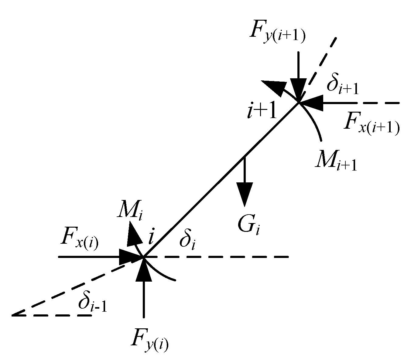
For quantitative analysis, the composite insulator with a structural height of L is divided into n segments, each with a length of Li = L/n. It is assumed that the mass of the composite insulator is uniformly distributed, the material parameters are the same at all locations, and each cross-section has a standard circular shape with a diameter of D. After bending, the angular position of each segment of the V-string composite insulator under a lateral wind load is denoted as δi (i = 1, 2, …, n). The mechanical model for the ith segment of the V-string composite insulator under a lateral wind load is depicted in Figure 2.
From Figure 2, it can be observed that the condition for the ith segment to reach an equilibrium state is as follows:
F x ( i ) = F x ( i + 1 ) F y ( i ) = F y ( i + 1 ) + G i M i + L 2 cos δ i ( F y ( i ) + F y ( i + 1 ) ) = M i + 1 + L 2 sin δ i ( F x ( i ) + F x ( i + 1 ) )
By employing the Newton–Raphson method to solve the above model, the maximum tensile and compressive stresses at any cross-section can be obtained as:
σ max ( i ) + = M i D 2 I P i A σ max ( i ) = M i D 2 I P i A         i = 1 , 2 , , n + 1
P i = F x ( 1 ) cos δ 1 + F y ( 1 ) sin δ 1       i = 1 F x ( i ) cos ( δ i 1 + δ i 2 ) + F y ( i ) sin ( δ i 1 + δ i 2 )       i = 1 , 2 , , n F x ( n + 1 ) cos δ n + 1 + F y ( n + 1 ) cos δ n + 1       i = n + 1
If we consider one end of the composite insulator as the coordinate origin, the coordinates of any other point on the composite insulator can be expressed as:
x i = k i 1 L k cos δ k y i = k i 1 L k sin δ k       i = 1 , 2 , , n + 1
In the above equations, Gi represents the self-weight of each segment, Fx(i) and Fy(i) denote the horizontal and vertical forces, Mi and Mi+1 are the bending moments at the two ends of the ith segment, D is the insulator cross-sectional diameter, I is the cross-sectional moment of inertia (I = πD4/64), and A is the cross-sectional area.
The method outlined provides an analytical relationship between the axial compression and maximum stress in the composite insulator [18]. To calculate the critical bending load for the composite insulator, it can be viewed as an elongated strut with hinged supports at both ends. The critical bending load F in Figure 1b can be expressed as follows:
F = π 2 E I L 2
I = π D 4 64
In the equation, E represents the elastic modulus of the composite insulator core rod and I is the moment of inertia in the rod’s cross-section. D is the core rod diameter and L is the height of the composite insulator structure.

2.2. The 3D Model and Material Constitutive Model of GFRP Core Rod Material

For one typical I-string composite insulator, 30% to 50% of the year is influenced by low-level wind-induced vibrations. Characteristics of these wind-induced vibrations include high frequency and small amplitude; both need a significantly extended period to result in fatigue life. Usually, there are over 10 million cycles during operation and at least 30 million cycles in the experiment. Consequently, such low-level wind-induced vibrations have minimal impact on the mechanical performance of composite insulators. However, compact V-string composite insulators have a higher probability of experiencing secondary distance vibrations under the lateral wind. Moreover, the split wires can induce composite insulator bending motion through torsional and secondary distance vibrations [19,20]. The alternating bending loads associated with these vibrations have larger amplitudes and lower frequencies. Therefore, they can reach their fatigue life in a relatively short period of time (usually less than one million cycles). As a result, they significantly impact the mechanical performance of composite insulators. In summary, the alternating bending loads significantly contribute to the relatively higher occurrence of decay-like fracture in compact V-string composite insulators.
There is a significant difference in strength between the epoxy resin matrix and the fiberglass in GFRP core rod material. If the GFRP core rod material is regarded as a single-phase anisotropic homogeneous material, it will lead to distortion in the results when we calculate the properties of the fiber. The reason for this is that the fiber properties are replaced by the properties of the matrix that are more prone to damage, which does not accurately represent the material’s behavior. Additionally, the damage and failure process at the fiber–matrix interface cannot be ignored. Therefore, in this section, the simulation and calculation of the damage evolution process of the material on the outer side of the bending arc of the GFRP core rod under alternating bending loads are performed using multiphase material finite element analysis and zero-thickness cohesive zone modeling.
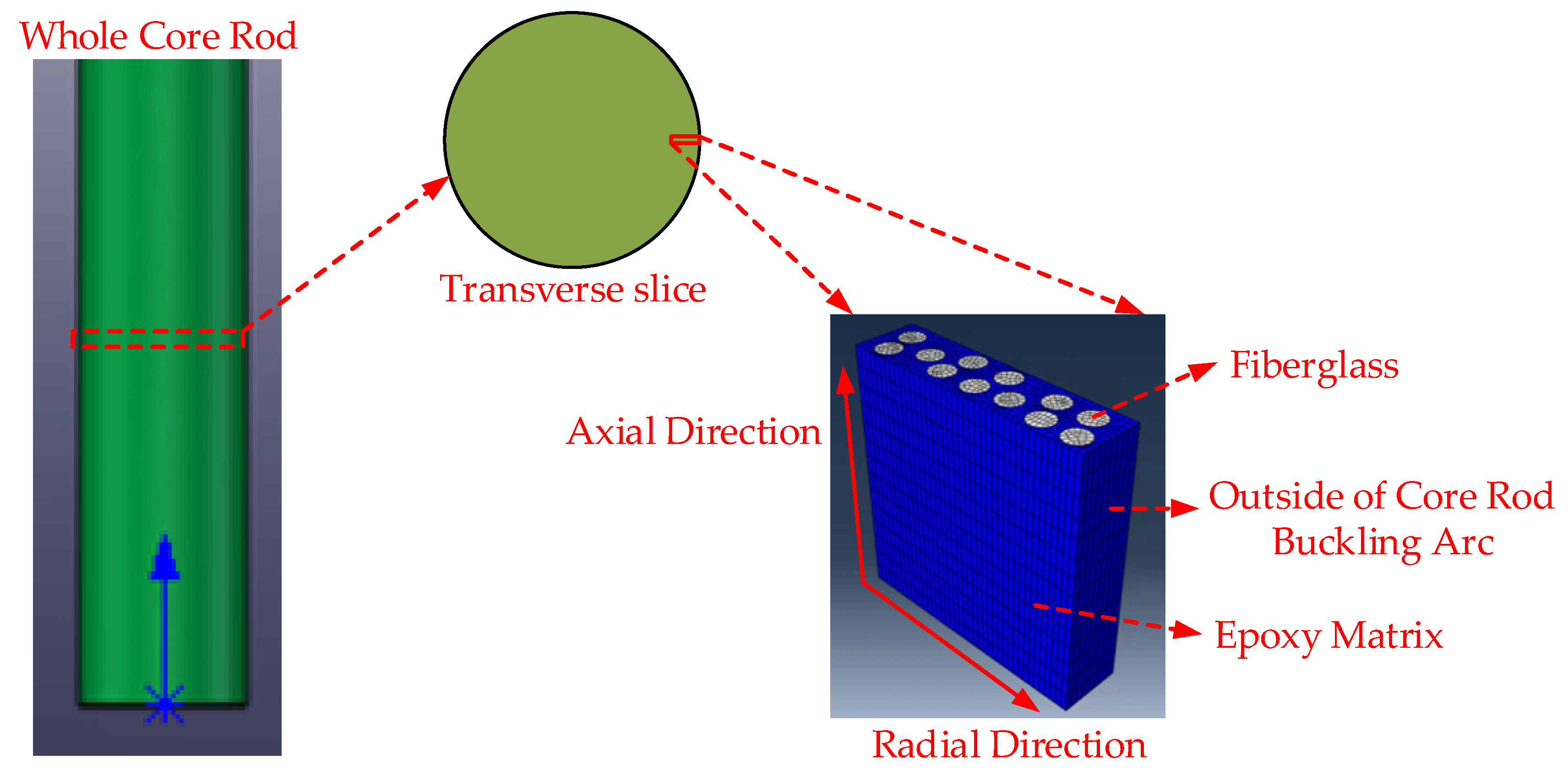
A model is created using finite element analysis software, Abaqus 2021, with material parameters shown in Table 1. The model is a cuboid of GFRP material measuring 200 μm × 200 μm× 50 μm, extracted from the outer side of a core rod’s bending circular arc. One face of the model corresponds to the outer surface of the core rod’s bending circular arc, while the remaining faces are entirely contained within the core rod. The model includes 12 fibers with a diameter of 20 μm, as depicted in Figure 3.
Before conducting calculations, it is essential to define the material constitutive models for the matrix and fibers using the VUMAT (user subroutine for defining material constitutive relations) within the Abaqus software.
E = ( 1 d m ) E 0
d m = u ¯ p l u ¯ f p l = L ε p l u ¯ f p l
u ¯ f p l = 2 G f σ y
In the formula, E is the stiffness after the matrix damage evolution. E0 is the stiffness before the damage and dm varies from 0 to 1 as the stiffness decreases when the stiffness is 0, dm = 1. u ¯ p l stands for plastic deformation. u ¯ f p l is the plastic deformation during matrix damage failure, ε p l represents the equivalent plastic strain, and L is the element length. Gf is the fracture energy per unit area and σ y is the material yield strength.
First, the fiberglass is defined as transversely isotropic along the axial direction with no plastic deformation stage. When the minimum principal stress at a node exceeds the compressive strength limit or the maximum principal stress exceeds the tensile strength limit, it is considered fiber fracture failure. The corresponding elements will be removed. Second, the epoxy resin matrix is defined as an isotropic elastic–plastic material. According to the Mises yield criterion, matrix damage is initiated when the maximum principal stress in a matrix element exceeds the strength limit, resulting in a stiffness reduction, as expressed in Equation (7). At this point, the matrix elements experience damage failure and are deleted. After defining the material constitutive models, the fiber–matrix interface considered as a pure viscous interface with zero thickness and no material properties is assigned. This section employs cohesive interface elements based on the traction–separation law to simulate the fiber–matrix interface.

2.3. Damage and Deterioration Process of GFRP Core Rod Material under Alternating Loads

A composite insulator specimen with an insulating distance of 1000 mm, a core rod diameter of 18 mm, and a sheath thickness of 4 mm can be taken as an example. Experimental results show that its maximum axial compression displacement is 300 mm. By selecting 30% of the maximum axial compression displacement as the amplitude of the alternating bending load for the entire core rod, it can be proportionally scaled to a micro-scale model, resulting in an alternating load amplitude (Lm) of 48 μm. With an alternating load frequency set at 0.5 Hz, the number of cycles of alternating loads (bending and resetting as one cycle) for various load amplitudes is specified as 100,000 cycles, 200,000 cycles, 300,000 cycles, and 400,000 cycles. The deterioration status of the GFRP core rod material under these conditions is illustrated in Figure 4.
The blue color in Figure 4 represents the initial color of the epoxy resin matrix unit. The initial color of the fiberglass unit is white. As fatigue intensifies, the color of the epoxy resin unit gradually develops from blue to light green, green, yellow, orange, light red and finally red. Figure 4 provides a visual representation of the damage evolution process of GFRP core rod materials under the influence of alternating bending loads. As the number of cycles of alternating loads increases, the GFRP core rod material gradually experiences fatigue and damage. Fatigue is initiated on the outer surface of the core rod’s bending arc and propagates toward the core rod’s interior. Simultaneously, with an increase in the amplitude of the alternating load, the fatigue rate accelerates, leading to a greater extent of damage. After subjecting the core rod to 100,000 cycles of alternating loads, the epoxy resin matrix on the outer surface of the core rod experiences significant stress. When an element matrix surpasses the maximum principal stress, the element matrix is deleted, indicating damage and detachment in that portion of the epoxy matrix. The detached matrix debris accumulates at the core rod–sheath interface. After applying alternating loads until 200,000 cycles, the glass fibers undergo fracture damage once they lose the protection of the epoxy matrix. The broken fiber debris detaches from the core rod’s surface, accumulating at the core rod–sheath interface. Upon reaching 400,000 cycles of alternating loads, the material on the core rod’s surface, with a thickness of approximately 100 μm, experiences varying degrees of damage. The decay-like composite insulators retrieved from sites also exhibit a significant accumulation of white cotton-like residues at the local core rod–sheath interface, as depicted in Figure 5. This phenomenon further confirms the rationality of the simulation results.
In summary, the outer surface of the composite insulator core rod’s bending arc under alternating loads experiences fatigue damage. As the number of cycles of alternating loads increases, the damaged area gradually expands and propagates toward the core rod’s interior. The mixture of debris generated in the damaged area, comprising epoxy matrix and fibers, accumulates at the core rod–sheath interface. These observations have been corroborated in actual instances of decay-like composite insulators [21].

3. Multi-Factor Aging Test of Composite Insulators under Wet-Hot and Alternating Loads

3.1. Sample Selection

The composite insulator samples elected for this experiment were provided by Xiangyang State Grid Composite Insulator Co., Ltd. (Xiangyang, China). The specific parameters of the specimens are shown in Table 2.

3.2. Experimental Setup

An artificially accelerated aging test platform with multiple factors, including humidity, temperature, and mechanical load, was constructed to simulate the actual operating conditions of V-string composite insulators. The main components of this test platform include a temperature and humidity control module and an alternating load application module. The alternating load application module was primarily utilized to mimic the unique mechanical characteristics of compact line V-string composite insulators. It accomplishes this by employing a servo actuator cylinder to exert reciprocating compressive and reset motions on the composite insulator, thereby applying alternating flexural loads.
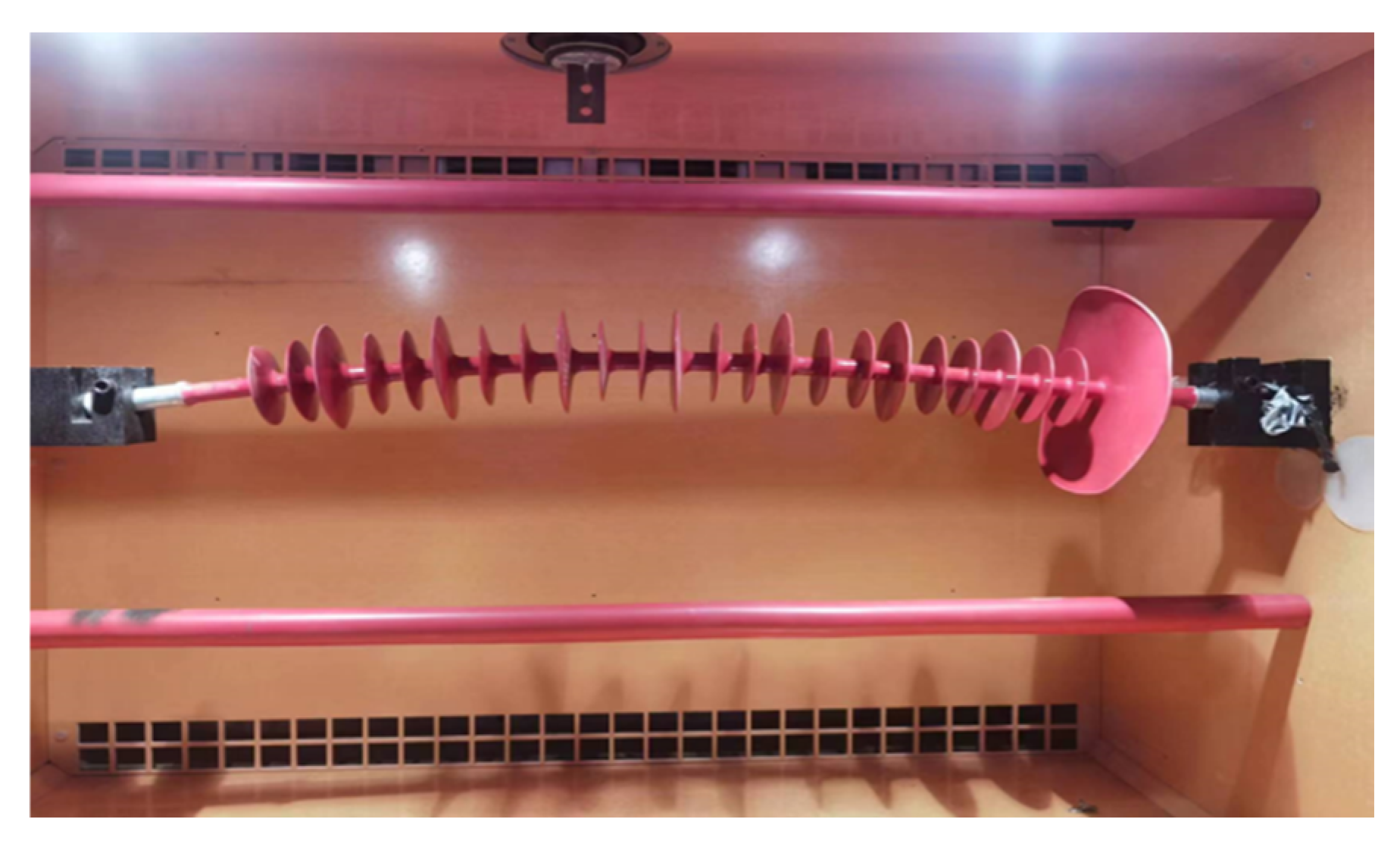
Referring to the environmental conditions in areas where composite insulators are prone to deterioration in China, the artificially accelerated aging test of composite insulators was set with an ambient temperature of 20–25 °C and a relative humidity of 75–80% RH. According to DL/T 1580-2016 [22], GB/T 34937-2017 [23], and GB/T 13096-2008 [24], combined with the operating condition on-site of composite insulators, it was determined that the axial compression amount of the alternating bending load applied in the test is 90 mm and the frequency is 0.5 Hz. The composite insulator subjected to bending loads is shown in Figure 6.

3.3. Testing and Characterization

3.3.1. Scanning Electron Microscopy Testing

Microscopic morphology analysis was conducted on surface material samples of composite insulator core rods at various aging stages using the SEM 230 scanning electron microscope produced by Alfa Chemistry Company in New York, NY, USA. The purpose was to investigate the changes in surface morphology at the point of buckling deterioration in GFRP core rods.

3.3.2. Thermogravimetric Analysis

The PerkinElmer STA6000 thermal gravimetric analyzer produced by PerkinElmer, Waltham, MA, USA, was employed to examine the thermal decomposition characteristics of surface material samples from composite insulator core rods. The test covered a temperature range of 30 °C to 800 °C, featuring a temperature rise rate of 10 °C/min, and utilized nitrogen as a protective gas.

3.3.3. Fourier Transform Infrared Spectroscopy Analysis

The IRTracer-100 Fourier transform infrared spectrometer produced by Shimadzu Corporation in Kyoto, Japan, conducted attenuation total reflection scanning tests on surface material samples from composite insulator core rods at various aging stages. The distinction in functional group content before and after aging was determined by analyzing the distinct absorbance peaks of functional groups on the characteristic infrared light peaks.

3.3.4. Charged Temperature Rise Experiment

Different composite insulator samples subected to varying alternating load cycles were tested for electrical temperature rise. To make the heating phenomenon more pronounced, the composite insulator samples were placed in a constant temperature and humidity chamber at 20 °C and 75% RH for 150 h before the test to ensure saturated moisture absorption [25,26]. Afterward, a 64 kV, 50 Hz AC voltage was applied to the high-voltage end fittings of the composite insulator while grounding the low-voltage end fittings. One hour after applying the AC voltage, the temperature rise images of the composite insulator were recorded using a FLIR T1040 handheld thermal imaging camera produced by Teledyne FLIR in Wilsonville, OR, USA.

3.3.5. Moisture Absorption Test

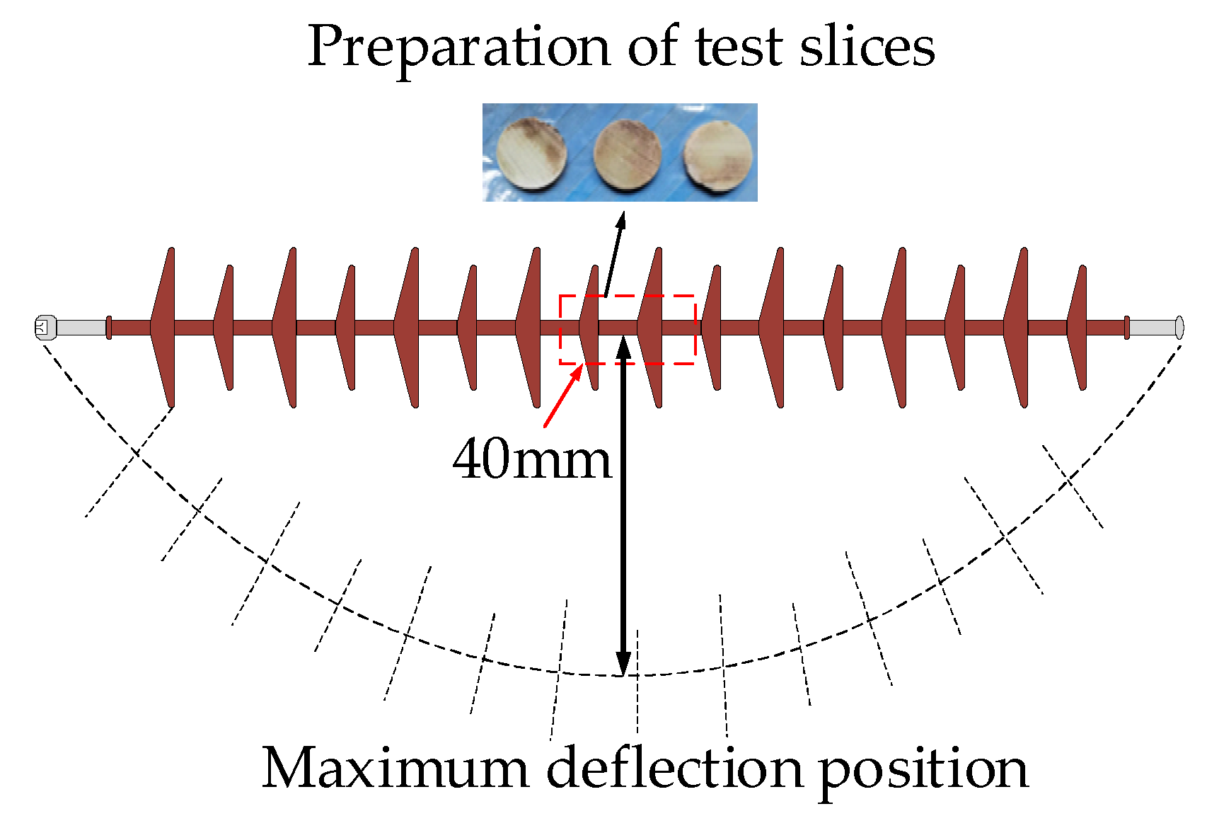
The most severely deteriorated section of the core rod from the composite insulator sample was used to prepare test specimens. The specific preparation steps are as follows. First, we cut a 40 mm long segment from the location with the maximum flexural deflection, which is the red-dashed rectangle area in Figure 7. Secondly, we prepared this segment into 20 pieces of specimens with a thickness of 2 mm and a diameter of 18 mm, as shown in Figure 7. After that, we used 100-grit sandpaper to uniformly sand the cross-section of the prepared samples. Continually, after grinding, we placed the pieces in a constant temperature and humidity chamber at 50 °C for 72 h. Finally, we measured each slice’s dielectric loss factor and the saturated moisture absorption rate after drying.
We conducted moisture absorption and weight gain tests on core rod materials in accordance with ASTM D5229/D5229M-20 [27]. The FA224C electronic analytical balance produced by the Shanghai Lichen Instrument Technology Co., Ltd. in Shanghai, China was selected for testing, with an accuracy of 0.1 mg. Each experiment was set up with 3 repeated samples. Samples were regularly taken from deionized water for weighing, and then quickly immersed back into ionized water to continue the moisture absorption test. The weighing results were taken as the average of the 3 samples, and the process was repeated until the weight of the samples no longer changed, that is, when they reached the saturation and moisture absorption level. The formula for calculating the moisture absorption rate Mt of the sample is as follows [28]:
M t = W t W 0 W 0 × 100 %
In the formula, W0 is the initial weight of the sample and Wt is the weight of the sample at time t. The average of the saturation moisture absorption rates measured on 20 test pieces of each core rod was taken to characterize the saturation moisture absorption rate of the corresponding brittle composite insulator test piece at a temperature of 20 °C.

3.3.6. Dielectric Loss Factor Test

The dielectric loss factor of the test piece was measured using the YG9100 fully automatic anti-interference precision dielectric loss tester produced by Shanghai Yanggao Electric Appliance Co., Ltd., Shanghai, China. Before the test, the upper and lower cross-sections of the test piece were uniformly pasted with tin foil. This ensured full contact between the cross-section and the measuring electrode, avoiding discharge interference from air gaps. The test frequency was 50 Hz. We then took the average value of the dielectric loss factor measured on 20 test pieces of each core rod to characterize the dielectric loss factor of the corresponding degraded composite insulator test piece.

3.4. Experiment Result

3.4.1. Appearance Inspection

Before conducting the test, pre-treatment of the specimens was performed. The sample was visually inspected to ensure they were free from any visible damage. Subsequently, the specimens’ surfaces were cleaned using deionized water. After cleaning, the sample was placed in a constant temperature and humidity chamber at 50 °C for 72 h to ensure thorough drying. After drying, the sample was transferred to the wet–thermal–mechanical multifactor composite insulator artificial accelerated aging test platform to initiate the aging test. Throughout the testing process, observations were made to record any changes in the appearance of the specimens. Furthermore, the protective sheath was removed for a comparative analysis of the core rod’s morphology.
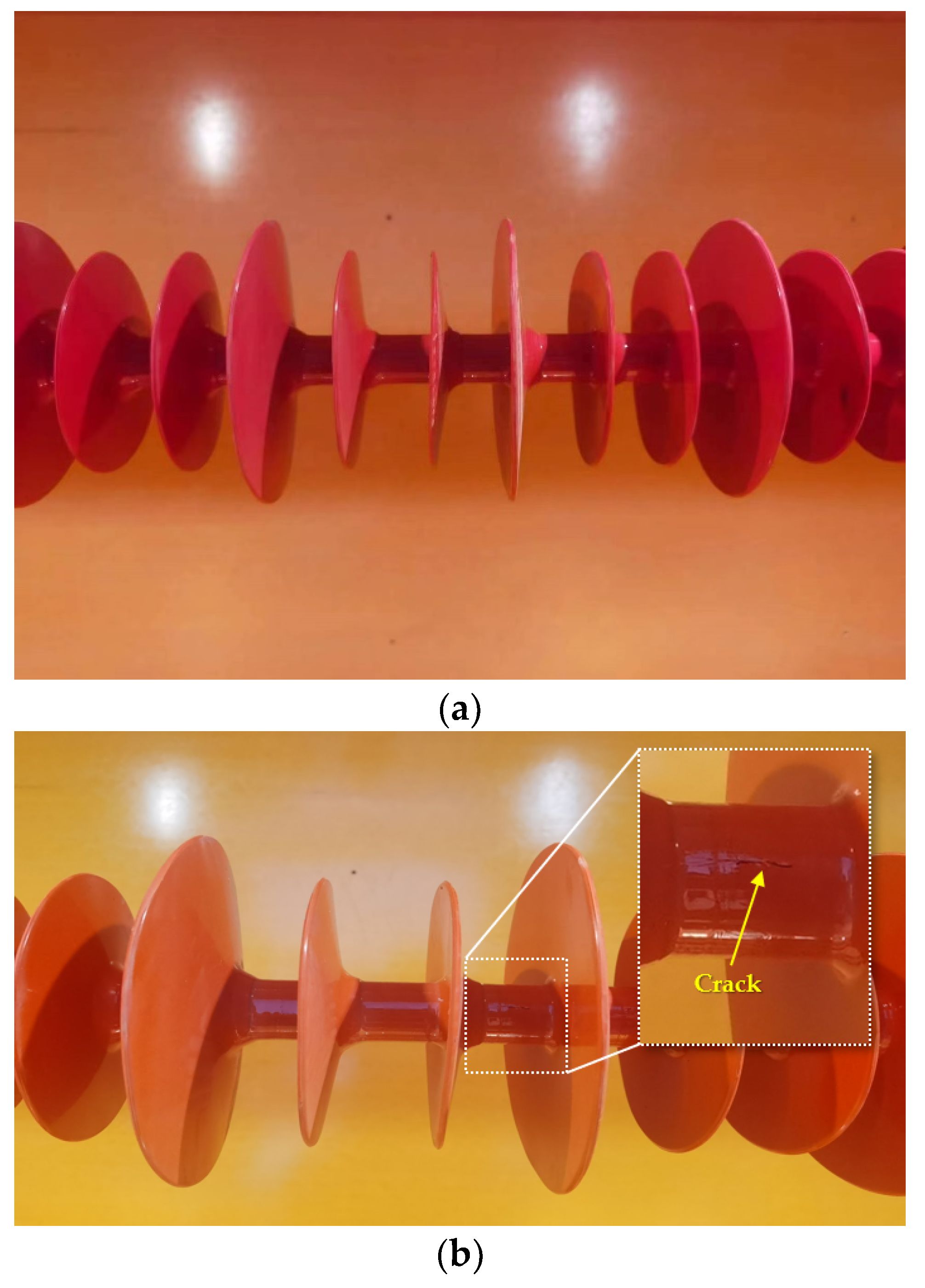
As shown in Figure 8, after 100,000 cycles of alternating load applications, the external appearance of the composite insulator exhibited no significant changes. However, after 200,000 cycles, cracks appeared in the insulator sheath. When the number of alternating load cycles reached 400,000, the insulator sheath exhibitd noticeable and extensive cracking in multiple areas.
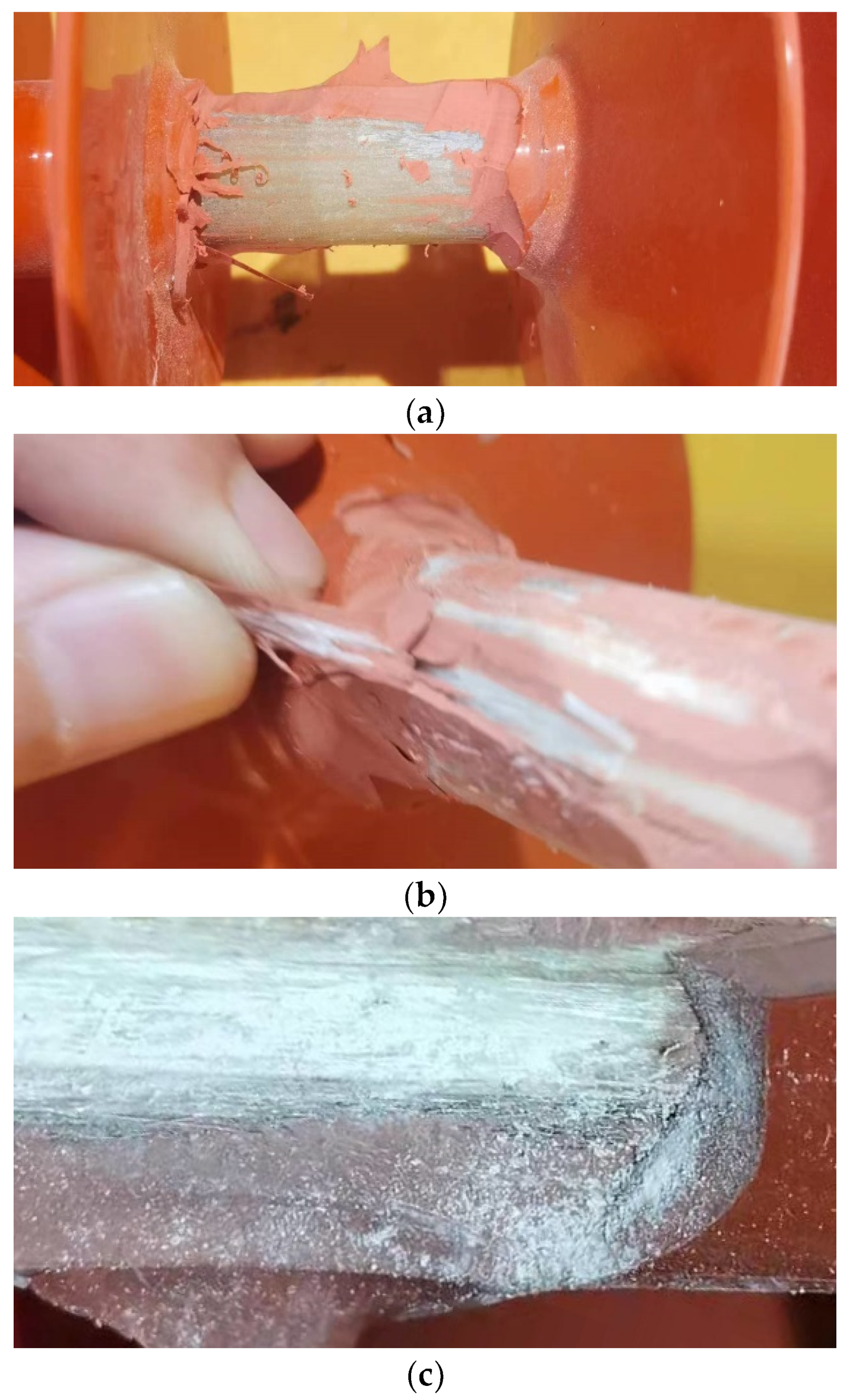
To further examine the deteriorated appearance of the core rod, a strip process was performed on the aged composite insulator sheath. The morphology of the core rod at the location with the maximum flexural deflection in the stripped composite insulator is depicted in Figure 9.
Figure 9 shows that with an increasing number of cycles of alternating load applications, the outer part of the core rod’s curved arc gradually deteriorated. After 100,000 cycles of alternating load applications, the adhesion between the composite insulator sheath and the core rod remained in good condition. The core rod’s surface slightly whitened, with no matrix fragments spilling out. After 200,000 cycles, partial delamination of the insulator sheath occurred, and there were some core rod fragments at the interface between the sheath and the core rod. When the number of alternating load cycles reached 400,000, it was found that a significant amount of white matrix powder spilled out when the composite insulator sheath was stripped. The core rod showed signs of hydrolysis, and its color changed from pale green to light yellow.

3.4.2. Microscopic Morphology Analysis

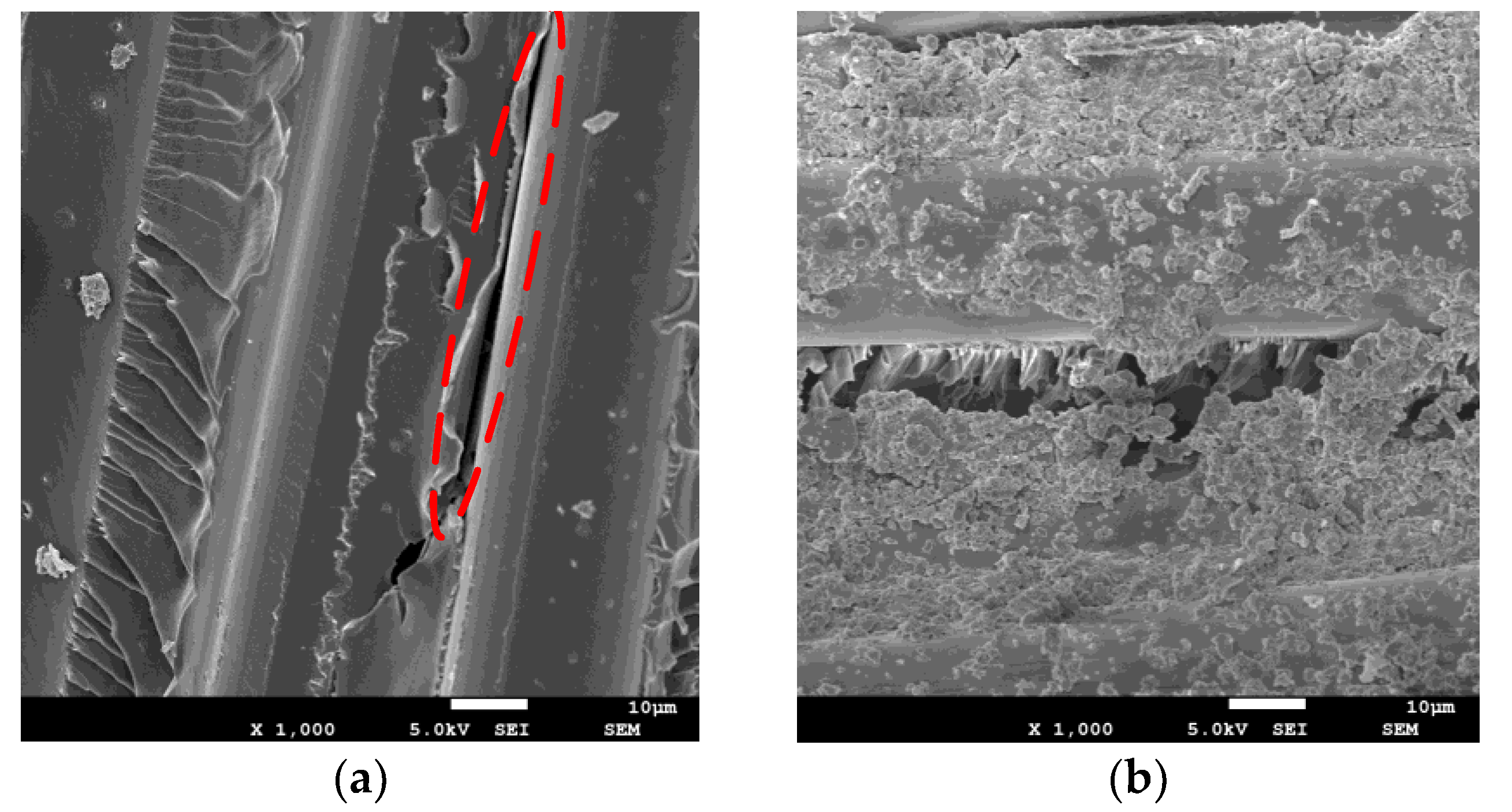
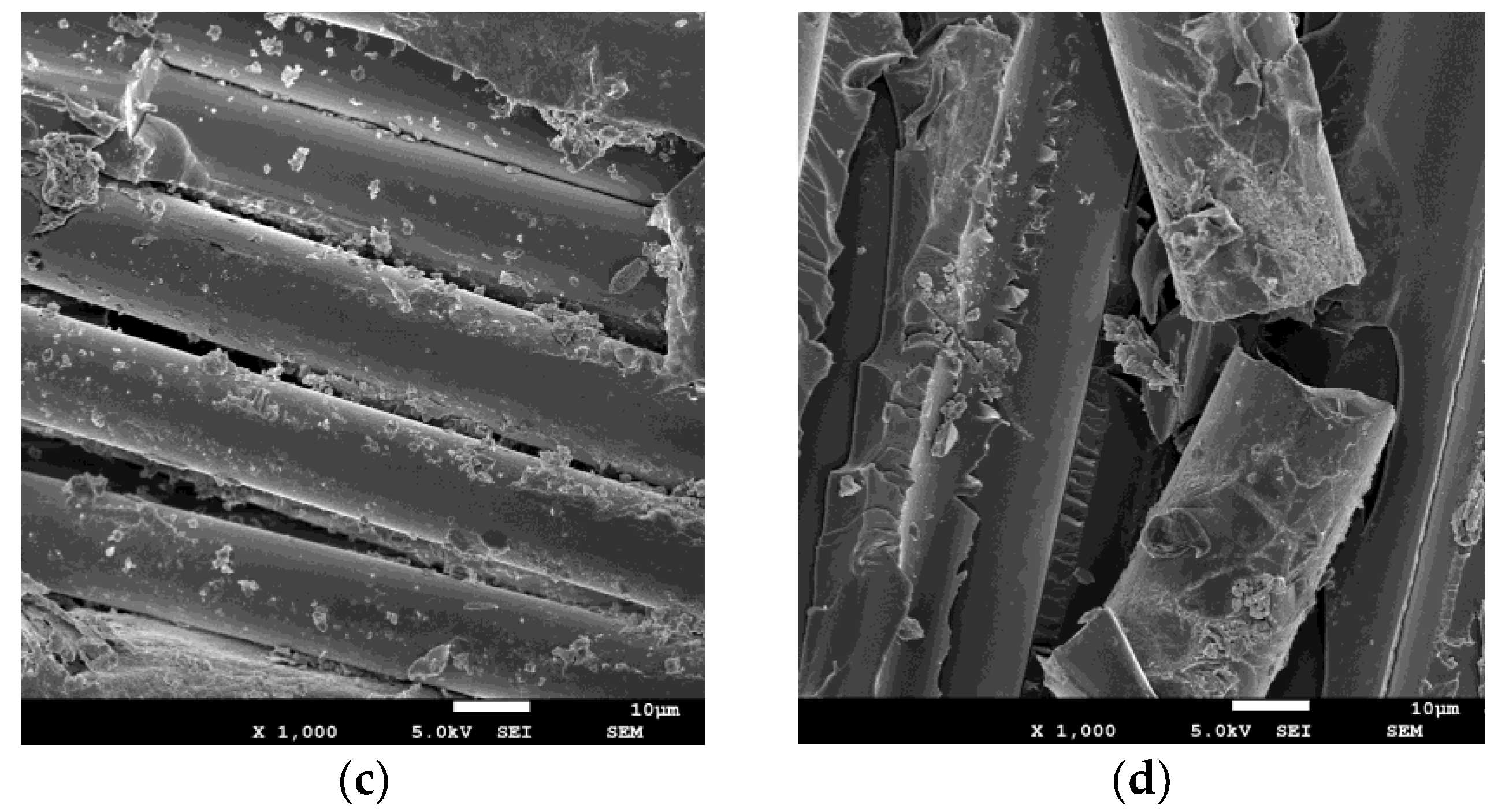
Figure 10 shows the microstructure of the core rod under four different fatigue states observed using a scanning electron microscope. Comparative analysis reveals that the extent of deterioration on the outer side of the core rod’s curved arc surface deepened with an increasing number of alternating bending load application cycles. After 100,000 cycles of alternating load applications, the glass fibers on the core rod surface remained intact without any signs of breakage. The epoxy resin also adhered well to the fibers, with no exposed glass fibers. However, there were instances of interface cracking between some fibers and the epoxy matrix, as shown in the red-dashed area in Figure 10. After 200,000 cycles of alternating loads, the core rod’s surface exhibited increased fatigue damage at locations with more significant flexural deflection. Still, no apparent hydrolysis suggests that moisture did not significantly penetrate the core rod area. After 300,000 cycles of alternating loads, the core rod’s surface epoxy matrix was severely damaged, and signs of deterioration were present, indicating that moisture had penetrated the interior of the composite insulator sheath in significant amounts and the matrix had started hydrolysis. After 400,000 cycles of alternating loads, the epoxy resin matrix material had undergone extensive hydrolysis at the severely deteriorated areas of the core rod’s surface. Some epoxy resin matrix fragments adhered to the fiber surface. Some fibers lost the epoxy resin matrix’s protection and were fractured [29,30].

3.4.3. Thermogravimetric Analysis Results

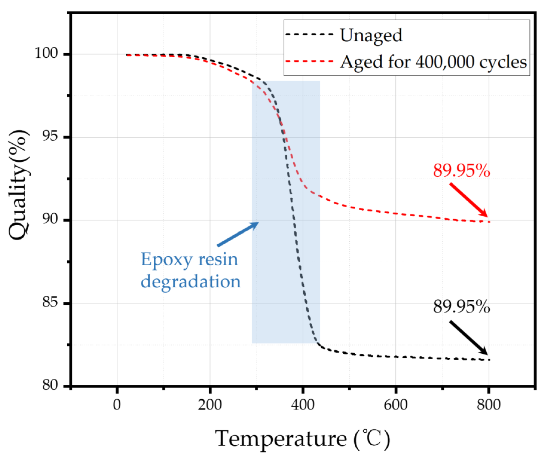
By heating and measuring the weight of samples at different temperatures, the epoxy resin content in the core rod could be analyzed, and the degree of deterioration of artificially aged core rods could be quantitatively analyzed. The thermogravimetric test results at the buckling point of composite insulator core rods before and after aging are shown in Figure 11. The epoxy resin decomposition temperature was reached when the temperature rises to 320 °C. When the temperature reached 430 °C, the epoxy resin was basmati-factorially decomposed, and the remaining masses of the samples before and after aging accounted for 81.63% and 89.95%, respectively. After the multi factor aging test, the epoxy resin in the core rod of the test sample degraded and the content decreased.

3.4.4. Fourier Transform Infrared Spectroscopy Analysis Results

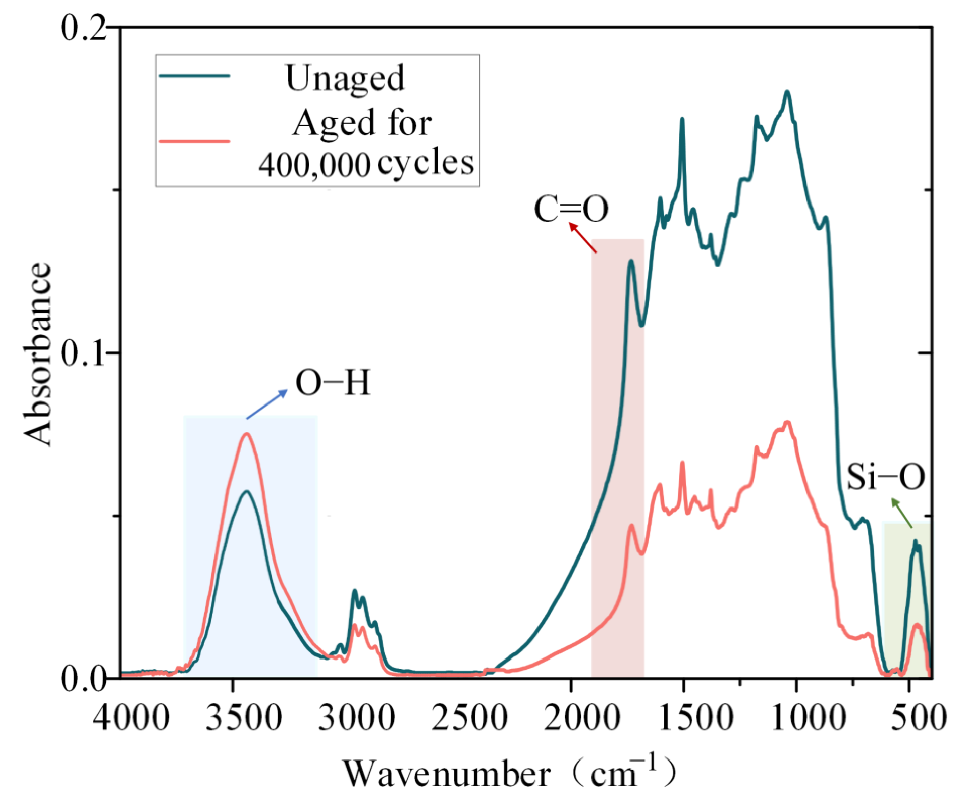
Through Fourier transform infrared spectroscopy analysis, it can be seen that there is no significant difference in characteristic peaks between the core rod after multiple factors aging and the unaged core rod. However, there was a difference in intensity between the same characteristic peak. As shown in Figure 12, the strength of C=O and Si−O in the core rod material had decreased to a certain extent, while the strength of O−H had increased, indicating that as aging progresses, the continuous invasion of moisture into the core rod in a high humidity environment leads to the continuous deterioration of the composite material.
From the above physical and chemical analysis results, it can be seen that as aging progresses, water continuously invades the composite insulator core rod, the epoxy resin matrix continuously hydrolyzes, and the degree of deterioration also intensifies.

3.4.5. Artificial Aging Test Sample Charged Temperature Rise Test

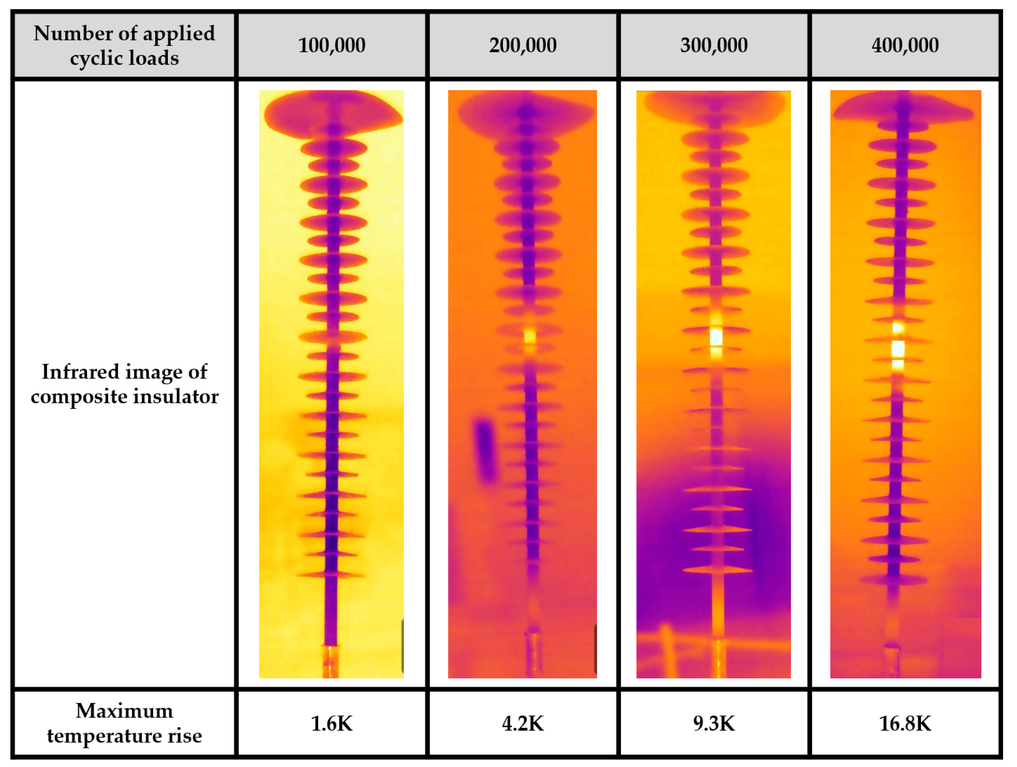
The infrared images of the abnormal temperature rise of composite insulators after applying different alternating loads are shown in Figure 13.
Figure 13 shows that as the number of alternating load cycles increases, the deterioration of the composite insulator samples progressively worsens—both the temperature rise range and the degree of temperature rise increase. When 100,000 cycles of alternating loads were applied, there was a slight temperature rise in the central region of the composite insulator, with a maximum temperature rise value of 1.6 K. Continuing to exert alternating load cycles up to 200,000, the temperature rise area of the composite insulator expanded in a small range, with the maximum temperature rise reaching 4.2 K. When the number of alternating load cycles reached 300,000, the temperature rise area of the composite insulator further expanded, and the maximum temperature rise value increased to 9.3 K. At this point, the heating phenomenon became more pronounced. Finally, when 400,000 alternating load cycles were applied, the maximum temperature rise amplitude of the composite insulator reached 16.8 K. The temperature rise area and the maximum temperature rise value were primarily located at the maximum flexural deflection of the composite insulator, indicating that this location experiences more severe deterioration.

3.4.6. Analysis of Moisture Absorption and Dielectric Loss Characteristics

The test specimens had uniform tin foil coverage on their top and bottom surfaces. It is assumed that external moisture only permeates from the sides of the samples. This assumption aligns with the moisture ingress observed during the temperature rise test. We then weighed and recorded the initial weight of each test piece after drying using an electronic balance. Each test piece was then placed in a constant temperature and humidity box to absorb moisture at a temperature of 20 °C and a humidity rate of 75%. We then took it out and weighed it immediately every 6 h, and calculated the moisture absorption rate of the test piece, totaling 480 h.
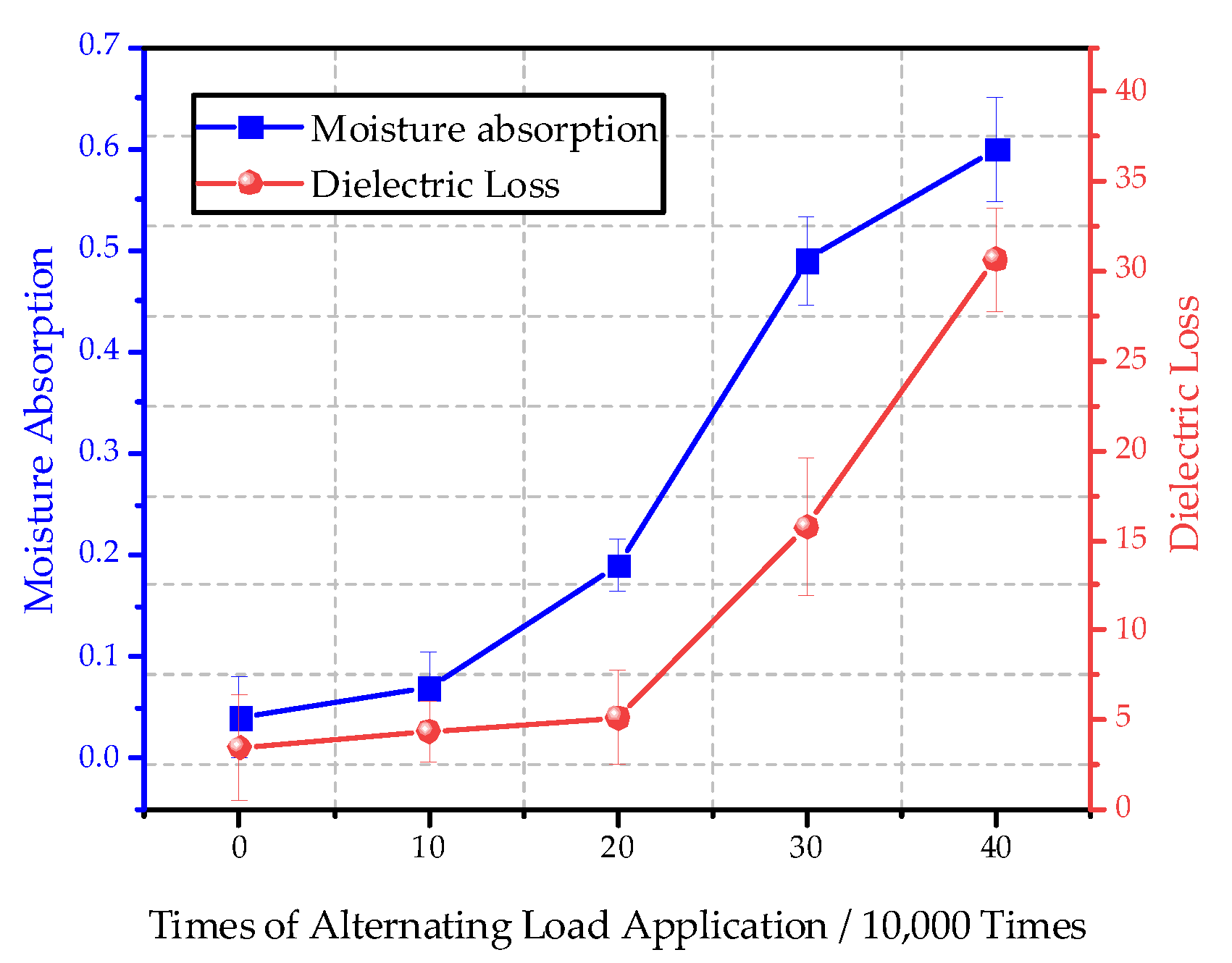
The results of the dielectric loss factor and saturation moisture absorption tests for each sample are presented in Figure 14. The figure shows that both the dielectric loss factor and saturation moisture absorption of the test samples exhibited a trend of initially slow increase, followed by a rapid rise, and then a subsequent slow growth with an increase in the number of times of alternating load applications. The test results indicate that the samples extracted from intact insulators had a dielectric loss factor and saturation moisture absorption rate of 3.45% and 0.04%, respectively. However, when subjected to 400,000 alternating load applications, the deteriorated core rod’s dielectric loss factor and saturation moisture absorption rate reached 30.68% and 0.6%, respectively, significantly increasing compared to the new samples.

4. Analysis and Discussion

The abnormal heating phenomenon in aged composite insulators is mainly attributed to dielectric losses. These losses are induced by the polarization effect of the dielectric material when exposed to the power frequency alternating electric field [31]. The equivalent electrical circuit model for the core rod material is illustrated in Figure 15.
In the diagram, Cg represents the capacitance equivalent to lossless polarization, while Rp and Cp represent the equivalent resistance and capacitance formed by lossy polarization, respectively. Rlk is the leakage resistance, which can be further divided into bulk leakage resistance and surface leakage resistance. Ilk represents the leakage current. For aged composite insulators, the decrease in insulation resistance in the deteriorated section of the core rod increases the leakage current, contributing relatively slightly to the temperature rise. Under the influence of high electric field strength in AC voltage, the polarization loss in the decay-like part of the composite insulator under AC power frequency is the leading cause of its abnormal temperature rise.
Furthermore, the power loss per unit volume of the dielectric can be expressed as:
p = E J r = E 2 ω ε tan δ
In Equation (11), E represents the distribution of the electric field intensity in the dielectric. Jr is the total active current density within the dielectric. ω is the angular frequency of the power frequency sinusoidal electric field. ε is the dielectric constant and tanδ is the loss angle tangent of the dielectric. This equation shows that the dielectric power loss is closely related to the magnitude of the electric field intensity and the dielectric loss factor. Furthermore, the scanning electron microscopy testing of slices of composite insulator core rods at different aging stages and physicochemical analysis showed that the surface epoxy matrix of the aged core rod material gradually deteriorated. The epoxy resin hydrolyzed continuously, resulting in numerous voids and microcracks inside. The emergence of these micro-defects not only led to distorted and abnormally increased electric fields in that region but also provided pathways for accelerated moisture ingress. An increase in the saturation moisture absorption rate macroscopically represents this. Additionally, water molecules are polar molecules. When they exist in the dielectric, they interact with the dielectric molecules, leading to the polarization of dielectric molecules and, consequently, an increase in dielectric material polarization loss. Coupled with the increase in dielectric loss in the core rod material during the aging process, macroscopically represented by the rise in the dielectric loss factor, the abnormal heating of the composite insulator is further promoted.

5. Conclusions

This article establishes a force model and a damage model to simulate and calculate the evolution of the damage process of the material outside the bending arc of the composite insulator core rod under alternating bending loads. A wet thermal mechanical multi-factor coupled artificially accelerated aging platform for composite insulators is established, and deterioration simulation tests for V-string composite insulators are carried out. The main conclusions are as follows:
(1)
Compact V-string composite insulators were found to be susceptible to the influence of alternating flexural loads. A detailed examination of the damage evolution in GFRP core rod material revealed that fatigue damage was initiated from the outer surface of the core rod’s bending arc due to alternating flexural loads. It propagated towards the core rod’s interior, beginning with epoxy resin matrix damage on its surface, subsequently leading to fiber breakage.
(2)
The establishment of a multi-factor composite insulator artificially aging platform, combining moisture, heat, and mechanical stress, allowed for accelerated aging tests. Microscopic morphology observation and physicochemical analysis indicates that while subjecting the test specimen to 400,000 alternating load cycles, the core rod underwent stages of surface damage, an increase damage, fatigue embrittlement, matrix hydrolysis, and fiber fracture. The deterioration primarily occurred on the outer side of the composite insulator’s bending arc.
(3)
Electric temperature rise tests were conducted on composite insulator specimens subjected to different numbers of alternating load cycles. It was observed that the deterioration of composite insulator specimens gradually intensified with an increasing number of alternating load cycles. Both the temperature rise range and the degree increased, with the temperature rise region and maximum temperature rise primarily occurring at the point where the bending deflection of the composite insulator was at its maximum, indicating that this position was the most severely deteriorated part.
(4)
Both the dielectric loss factor and saturation moisture absorption rate of the test samples exhibited an initially slow increase, followed by rapid growth and then a gradual increase with an increasing number of alternating load cycles. Test results showed that the dielectric loss factor and saturation moisture absorption rate for slices from the new insulator were 3.45% and 0.04%, respectively. However, after 400,000 alternating load cycles, the deteriorated core rod’s dielectric loss factor and saturation moisture absorption rate significantly increased to 30.68% and 0.6%, respectively, in contrast to the new samples.
(5)
As the times of alternating flexural loads increased, the depth of core rod deterioration continuously deepened. The microcracks and pores formed inside the core rod distort the electric field and provided pathways for accelerated moisture ingress. This, in turn, increased dielectric material polarization loss, causing abnormal temperature to rise in the deteriorated section of the composite insulator.

Author Contributions

Data curation, L.D., H.L. and J.G.; formal analysis, X.Y. and P.W.; funding acquisition, X.Y.; investigation, Z.L.; methodology, X.Y., Y.Z. and P.W.; project administration, L.D. and J.L.; resources, H.L.; software, J.Z., Z.L. and Y.Z.; supervision, J.L. and P.W.; validation, J.Z. and J.G.; visualization, Z.L.; writing—original draft, X.Y., L.D. and Y.Z.; writing—review and editing, H.L., J.Z., J.L. and J.G. All authors have read and agreed to the published version of the manuscript.

Funding

This research was funded by the State Grid Corporation of China Technology Project, Grant Number TSS2022-11, and the APC was funded by State Grid Corporation of China.

Data Availability Statement

Dataset available on request from the authors.

Conflicts of Interest

Authors Xiaoyu Yi, Hongliang Liu, Jiaxin Zhang, Jie Liu were employed by the company State Grid Hebei Energy Technology Service Co., Ltd. Author Likun Ding was employed by the company State Grid Hebei Electric Power Co., Ltd. The remaining authors declare that the research was conducted in the absence of any commercial or financial relationships that could be construed as a potential conflict of interest.

References

  1. Liang, X.; Gao, Y.; Wang, J.; Li, S. Rapid Development of Silicone Rubber Composite Insulator in China. High Volt. Eng. 2016, 42, 2888–2896. (In Chinese) [Google Scholar]
  2. Yang, L.; Yu, J.; Guo, Y.; Chen, S.; Tan, K.L.; Li, S. An Electrode-Grounded Droplet-Based Electricity Generator (EG-DEG) for Liquid Motion Monitoring. Adv. Funct. Mater. 2023, 33, 2302147. [Google Scholar] [CrossRef]
  3. Liu, Z. Present Situation and Prospects of Applying Composite Insulators to UHF Transmission Lines in China. Power Syst. Technol. 2006, 30, 1–7. (In Chinese) [Google Scholar]
  4. Guan, Z.; Peng, G.; Wang, L. Application and Key Technical Study of Composite Insulators. High Volt. Eng. 2011, 37, 513–519. (In Chinese) [Google Scholar]
  5. Dai, J. Study of Brittle Fracture of High Voltage Composite Insulators. Master’s Thesis, Tsinghua University, Beijing, China, 2006. (In Chinese). [Google Scholar]
  6. Liang, X.; Huang, L.; Wang, S. Composite insulator flashovers caused by bird dropping and unknown reasons. Power Syst. Technol. 2001, 25, 13–16. (In Chinese) [Google Scholar]
  7. Zhang, Y.; Hou, S.; Geng, J.; Gong, Y.; Zhong, Z. Diagnosis Method of Decay-like Composite Insulators in a High-Humidity Environment Based on Characteristic Coefficient of Temperature Rise Gradient. Polymers 2023, 15, 2715. [Google Scholar] [CrossRef] [PubMed]
  8. Wang, J.; Liang, X.; Gao, Y. Failure analysis of decay-like fracture of composite insulator. IEEE Trans. Dielectr. Electr. Insul. 2014, 21, 2503–2511. [Google Scholar] [CrossRef]
  9. Gao, Y.; Liang, X. Study on Decay-Like Fracture of Composite Insulator, Part II: Experimental Simulation and Preventive Method Discussion of Decay-Like Fracture. Proc. CSEE 2016, 36, 5070–5077+5132. (In Chinese) [Google Scholar]
  10. Zeng, L. Study on Abnormal Heating and Hygrothermal Aging Characteristics of Composite Insulators. Master’s Thesis, South China University of Technology, Guangzhou, China, 2019. (In Chinese). [Google Scholar]
  11. Zhao, Y. Study on the Deterioration Characteristics of the Core of Composite Insulators under Hygrothermal Environment. Master’s Thesis, North China Electric Power University, Beijing, China, 2018. (In Chinese). [Google Scholar]
  12. Ma, X. Research on the Influence of Moisture Immersion on the Internal Deterioration Process of Composite Insulator. Master’s Thesis, Dalian University of Technology, Dalian, China, 2022. (In Chinese). [Google Scholar]
  13. Noonan, M.; Obande, W.; Ray, D. Simulated End-of-Life Reuse of Composites from Marine Applications Using Thermal Reshaping of Seawater-Aged, Glass Fibre-Reinforced Acrylic Materials. Compos. Part B Eng. 2024, 270, 111118. [Google Scholar] [CrossRef]
  14. Stupar, S.; Vuksanović, M.M.; Mijin, D.Ž.; Milanović, B.C.; Joksimović, V.J.; Barudžija, T.S.; Knežević, M.R. Multispectral Electromagnetic Shielding and Mechanical Properties of Carbon Fabrics Reinforced by Silver Deposition. Mater. Chem. Phys. 2022, 289, 126495. [Google Scholar] [CrossRef]
  15. Stupar, S.; Vuksanović, M.M.; Mijin, D.Ž.; Bučko, M.; Joksimović, V.J.; Barudžija, T.S.; Tanić, M.N. Functional Nano-Silver Decorated Textiles for Wearable Electronics and Electromagnetic Interference Shielding. Mater. Today Commun. 2023, 34, 105312. [Google Scholar] [CrossRef]
  16. Nicolalde, J.F.; Yaselga, J.; Martínez-Gómez, J. Selection of a Sustainable Structural Beam Material for Rural Housing in Latin América by Multicriteria Decision Methods Means. Appl. Sci. 2022, 12, 1393. [Google Scholar] [CrossRef]
  17. Chen, Y.; Xue, W.; Liu, Y. Influence of Silicone Rubber Content of Shed and Sheath on Composite Insulator Lifespan. High Volt. Eng. 2022, 48, 736–752. (In Chinese) [Google Scholar]
  18. Le, B.; Hou, L.; Wang, L.; Zhu, P. Study on loading characteristics of V type composite insulator used in 330 kV compact line. Proc. CSEE 2005, 25, 91–95. (In Chinese) [Google Scholar]
  19. Diana, G.; Cheli, F.; Manenti, A.; Nicolini, P.; Tavano, F. Oscillation of Bundle Conductors in Overhead Lines due to Turbulent Wind. IEEE Trans. Power Deliv. 1990, 5, 1910–1922. [Google Scholar] [CrossRef]
  20. Zhu, K.; Liu, B. Calculation of Torsional Stiffness of Bundle Conductors in Overhead Transmission Lines. Power Syst. Technol. 2010, 34, 210–214. (In Chinese) [Google Scholar]
  21. Zhang, Z.; Pang, G.; Lu, M.; Gao, C.; Jiang, X. Research on Silicone Rubber Sheds of Decay-Like Fractured Composite Insulators Based on Hardness, Hydrophobicity, NMR, and FTIR. Polymers 2022, 14, 3424. [Google Scholar] [CrossRef] [PubMed]
  22. DL/T 1580-2016; Technical Specification for Core of Long Rod Composite Insulators for a. c. or d. c. Systems. China National Energy Administration: Beijing, China, 2016.
  23. GB/T 34937-2017; Insulators for Overhead Lines—Composite Suspension and Tension Insulators for d. c. Systems with a Nominal Voltage Greater than 1500 V—Definitions, Test Methods and Acceptance Criteria. China National Standardization Administration: Beijing, China, 2017.
  24. GB/T 13096-2008; Test Method for Mechanical Properties of Pultruded Glass Fiber Reinforced Plastic Rods. China National Standardization Administration: Beijing, China, 2008.
  25. Zhang, Z.; Huang, Q.; Geng, J.; Liu, Q.; Zhang, S. Defect Identification of Composite Insulator Based on Infrared Image. Polymers 2022, 14, 2620. [Google Scholar] [CrossRef]
  26. Gao, S.; Liu, Y.; Li, L. A Comparative Study of Abnormal Heating Composite Insulators. Polymers 2023, 15, 2772. [Google Scholar] [CrossRef]
  27. ASTM D5229/D5229M-20; Standard Test Method for Moisture Absorption Properties and Equilibrium Conditioning of Polymer Matrix Composite Materials. ASTM International: West Conshohocken, PA, USA, 2020.
  28. Li, X.; Zhang, Y.; Chen, L.; Fu, X.; Geng, J.; Liu, Y.; Gong, Y.; Zhang, S. Study on the Ageing Characteristics of Silicone Rubber for Composite Insulators under Multi-Factor Coupling Effects. Coatings 2023, 13, 1668. [Google Scholar] [CrossRef]
  29. Wang, Q.; Bao, W.; Gao, Y.; Liu, S.; Liu, S.; Zuo, Z.; Wu, C.; Liang, X. Influence of Surface Discharge on Resin Degradation in Decay-like Fracture of Composite Insulators. Polymers 2023, 15, 790. [Google Scholar] [CrossRef] [PubMed]
  30. Yuan, Z.; Wang, C.; Jin, L.; Tu, Y.; Zhang, Y.; An, Z.; Zhao, Y. A Modified Langmuir Model for Moisture Diffusion in UGFRE of Composite Insulator Considering the Composite Degradation. Polymers 2022, 14, 2922. [Google Scholar] [CrossRef] [PubMed]
  31. Zhong, Z.; Chen, Y.; Liu, Y.; Hou, S.; Geng, J. Study on the influence mechanism of ambient humidity on the temperature rise of decay-like composite insulators. High Volt. 2022, 7, 916–924. [Google Scholar] [CrossRef]
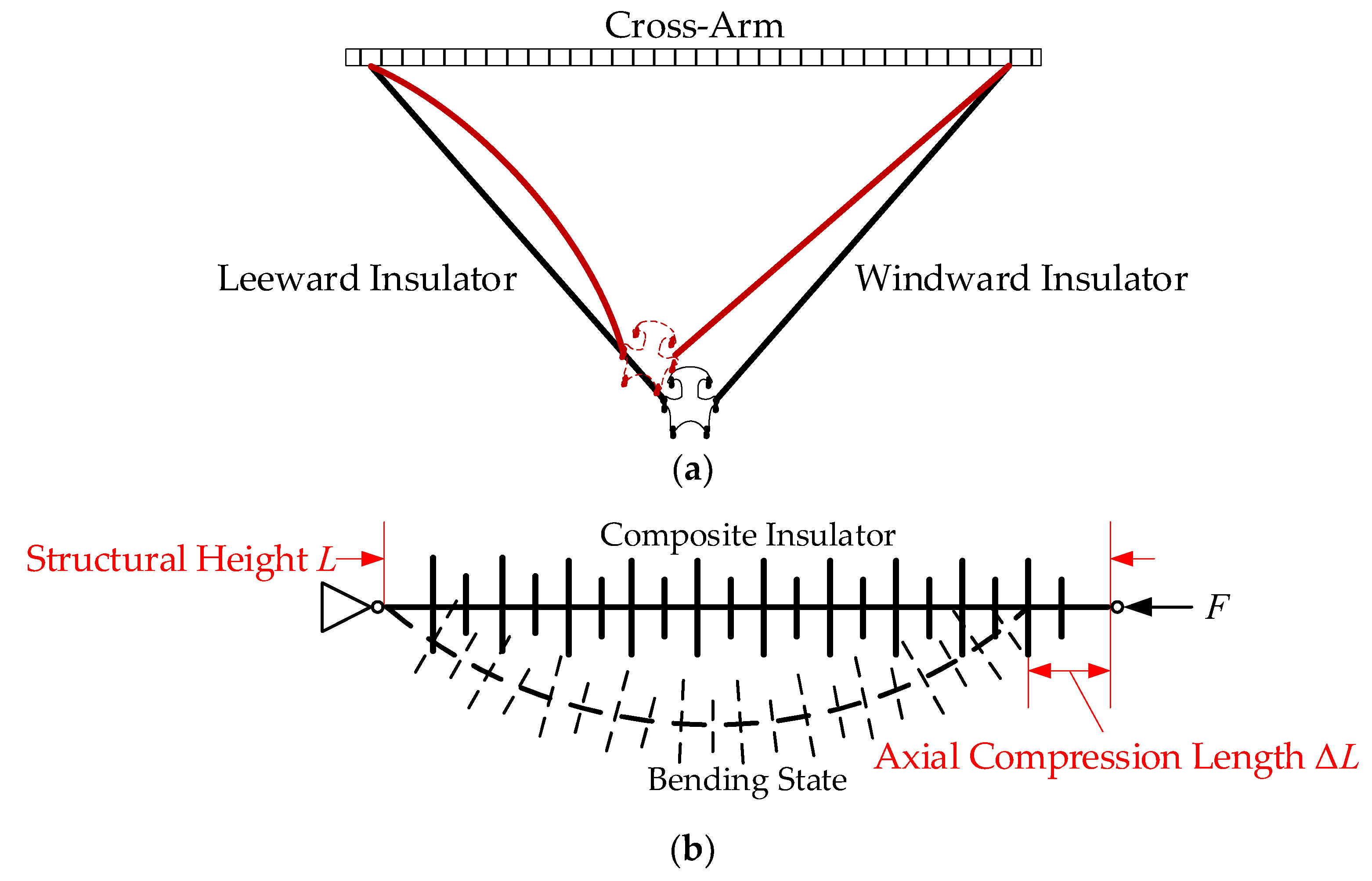
Figure 1. Bending state of v-string composite insulators under lateral wind loads. (a) Bending state, (b) compression stroke.
Energies 17 00423 g001
Figure 2. Mechanical model for the ith segment of the insulator.
Energies 17 00423 g002
Figure 3. Three-dimensional polyphase model of GFRP core rod material.
Energies 17 00423 g003
Figure 4. Deterioration process of GFRP core rod material under bending loads; (a) N = 1 × 10⁵; (b) N = 2 × 10⁵; (c) N = 3 × 10⁵; (d) N = 4 × 10⁵.
Energies 17 00423 g004
Figure 5. Debris at the core rod–sheath interface of a brittle composite insulator.
Energies 17 00423 g005
Figure 6. Schematic diagram of the composite insulator bearing a bending load.
Energies 17 00423 g006
Figure 7. Schematic diagram of the sampling area and preparation for test pieces.
Energies 17 00423 g007
Figure 8. Appearance of composite insulators tested after applying different number of times of alternating loads: (a) 100,000 times, (b) 200,000 times, and (c) 300,000 times.
Energies 17 00423 g008aEnergies 17 00423 g008b
Figure 9. Appearance of composite insulator core rod tested after applying different number of times of alternating loads: (a) 100,000 times, (b) 200,000 times, and (c) 300,000 times.
Energies 17 00423 g009
Figure 10. Microscopic morphology of core rods with different fatigue times; (a) N = 1 × 10⁵; (b) N = 2 × 10⁵; (c) N = 3 × 10⁵; (d) N = 4 × 10⁵.
Energies 17 00423 g010aEnergies 17 00423 g010b
Figure 11. Thermogravimetric analysis results of composite insulator core rods before and after aging.
Energies 17 00423 g011
Figure 12. Infrared spectroscopic analysis results of composite insulator core rods before and after aging.
Energies 17 00423 g012
Figure 13. Infrared heating images of composite insulators after being electrified under different cycles of alternating loads.
Energies 17 00423 g013
Figure 14. Moisture absorption and dielectric loss characteristics of composite insulator thin specimens.
Energies 17 00423 g014
Figure 15. Dielectric equivalent circuit diagram.
Energies 17 00423 g015
Table 1. Material model parameters.
Material PhaseParameterValue
FiberglassDensity970 kg/m3
Modulus of elasticityE1 = 89,000 MPa, E2 = E3 = 8610 MPa
Poisson’s ratioσ12 = σ13 = 0.3, σ23 = 0.45 MPa
Shear modulusG12 = G13 = 4160 MPa, G23 = 3000 MPa
Epoxy MatrixDensity1200 kg/m3
Modulus of elasticity3450 MPa
Poisson’s ratio0.35
Shear modulus0
Yield stress74.7 MPa
InterfaceNormal strength1000 MPa
Shear strength385 MPa
Table 2. Parameters of composite insulator samples.
ParameterValue
Rated mechanical tensile load70 kN
Insulation distance1000 mm
Min nominal creepage distance3150 mm
Number of umbrella skirts (large/small)25(9/16)
Core rod diameter18 mm
Sheath thickness4 mm
Maximum axial compression300 mm
Disclaimer/Publisher’s Note: The statements, opinions and data contained in all publications are solely those of the individual author(s) and contributor(s) and not of MDPI and/or the editor(s). MDPI and/or the editor(s) disclaim responsibility for any injury to people or property resulting from any ideas, methods, instructions or products referred to in the content.