Article

An Investigation of Structural Strength of Nuclear Fuel Spacer Grid

KEPCO International Nuclear Graduate School, Ulsan 45014, Republic of Korea
*
Author to whom correspondence should be addressed.
Energies 2024, 17(2), 458; https://doi.org/10.3390/en17020458
Submission received: 14 November 2023 / Revised: 20 December 2023 / Accepted: 29 December 2023 / Published: 17 January 2024

Abstract

:
This paper compares and discusses the methods for evaluation of the structural integrity of the mid spacer grid of nuclear fuel assembly via a finite element analysis of 3D shell elements. The structural stiffness of the spacer grid is determined by applying either force or deformation as loads onto the spacer grid for both the square load and shear load directions. This study is an extension of a single-cell strength analysis of a spacer. External events such as seismic activities that might happen in a nuclear reactor are able to transfer loads onto nuclear components in random directions, which can be broken down into square and shear loadings. The structural strength indicated by the force reaction against the input displacement load was proven to be smaller such that the same displacement square load is around 260 times greater than the shear load. Due to the weakness in shear stiffness, the maintenance of a spacer grid structure is more vulnerable against out-of-plane loads. This indicates that the shear load needs to be considered in studies of fuel assembly integrity assessment for newly developing fuel design, as well as existing fuel assembly designs.

1. Introduction

A concern regarding the structural integrity of fuel assembly was discovered from the contact and impact between fuel assemblies (FAs) coming from torsional motion induced during operational states [1]. They designed lumped mass and beam elements to represent reactor structural dynamics due to its complexity. A model reduction technique was suggested in the research to create a 3D FA model, using lumped mass, beam, and shell elements, without eliminating the 3D response of FA. The findings revealed that, in addition to the beam mode of response, the result also included the FA’s torsional mode of response. It is reasonable to presume that the dynamic behavior of FAs in the core is unlikely to operate in equilibrium and will instead be random, interacting with one another as input loads change over time. This sparked concerns regarding the reliability of the fuel assembly spacer grid being strong enough during abnormal operating conditions to limit fuel clad damage, preventing fuel clad rupture and stopping the leakage of radioactive elements.
FA components are required to comply with Level D service limits to maintain structural integrity in the case of a loss-of-coolant accident (LOCA) [2]. The design impact loads for a LOCA event shall not be exceeded by the load coming from spacer grids. Therefore, the spacer grid’s design must be sustained in normal operating conditions and in the case of an LOCA event for it to be accepted in evaluation processes.
Numerous research studies have been performed to investigate the fuel assembly design, including the evaluation of its structural integrity, as well as the fretting wear between spacer grid and fuel rods.
Namgung ran a study on the interaction of a spacer grid with a fuel rod, using the finite element analysis (FEA) approach [1,3]. To counter the complexity of the model design, they conducted the analysis on a single cell of spacer grid combined with a fuel rod, with the thermal loads obtained from a thermal analysis of 2D axisymmetric simulation of the fuel rod, fill gas, and fuel pellet. The spacer grid cell was tested with square and shear load of force, revealing that the stiffness of the spacer grid, when exposed to shear load, is 2500 times smaller compared to when receiving the square load. Since this is a single-cell model, it is important to verify whether this model can represent a full spacer grid model in a structural analysis.
In a study by Song et al. [4], the spacer grid’s structural and mechanical performances were investigated in-depth. The main objective was to utilize analysis and experimentation to improve the lateral stiffness and spring and dimple design. They recommended employing laser welding techniques rather than traditional spot welding of grid straps to increase the stiffness of the spacer grid. Additionally, by using FEA and experiments, they evaluated the crush strength of the spacer grid for various welding procedures and demonstrated that the proposed welding techniques outperform standard welding techniques. It is important to note that the loading on the spacer was oriented perpendicularly to the grid strap in their research, meaning that it was a square load.
A finite element model (FEM) of the spacer grid and an estimation of its buckling strength were carried out by Yoo et al. [5]. They performed a spacer grid spring and dimple stiffness test and a fuel rod drag test, and then they conducted static compression and dynamic impact tests on the spacer grid. They later analyzed the results to verify the them. Their research was also performed using a square load. By performing an analysis of the impact on partial spacer grids, they highlighted the significance of the boundary conditions of the spacer grid by predicting the impact load and impact velocity at which buckling occurs.
Yvon et al. conducted a crush test on irradiated Zircaloy-4 [6]. They crushed a squarely set full spacer grid with a displacement load along the grid strap direction. The irradiation adversely affected the spacer grid when the grid started crumbling from a 1 mm displacement input. The test demonstrated that the lattice shape of the spacer grid is still maintained when subjected to a displacement load up to 15 mm. Among the major limitations in their experiments was that the diagonal crumble of the spacer grid was not included. The grid maintained its lattice shape in their study since the loadings were applied in the direction of the grid strap, i.e., in-plane displacement. Rather than buckling, the square shape of the lattice of grid will collapse and form a rhombus shape, and the grid would crumble if the loadings were out of plane for the grid strap. The applied load will also be directly transferred to the fuel rod, resulting in severe cases as a result of the change in the grid shape to rhombus from square.
In a report to NRC on PWR fuel assembly structural response to externally applied dynamic excitations by Areva [7], the mathematical model of fuel assembly consisted of a lumped mass and stick model, and separate vertical and horizontal models were used. It was lacking a 3D model analysis, which was used in this study.
Yoon et al. [8] constructed a partial grid of 5 × 5 cells to perform an impact test. They also performed a dynamic impact analysis of the grid structure under lateral impact load, using the multipoint constraint (MPC) equation. They achieved an FEM model that behaves almost similarly to a real model by modifying the stiffness of the grid model and suggested that their model is suitable for use to predict a spacer grid’s dynamic buckling behavior.
Shin et al. [9] suggested the use of an FEM instead of mathematical modeling for a spacer grid analysis to more accurately represent the actual model with confidence. Their study focused on reducing the fretting wear on a spacer grid spring.
To determine the structural behavior of fuel assemblies, Schettino et al. [10] simulated the compression strength of the spacer grid according to experimental predictions by compressing a 3D model of a 16 × 16 spacer grid under square loading.
With reference to the papers above, it is important to evaluate the spacer grid strength under various operating conditions so that it does not undergo large deformation and damage fuel clad. A displacement load of 1 mm is enough to produce deformation on a spacer grid [6,8,10]. Therefore, the behavior of the spacer grid under all loading conditions is of important concern. In order to simplify the analysis, loadings are decomposed into a square load and shear load, which then can be combined to represent any loading condition.
This paper brings an approach to comprehensively evaluate the spacer grid’s behavior under square and shear displacement loadings via an FEA approach, using ANSYS. We would like to emphasize that the modeling of a full spacer grid using 3D shell element is the first and most important achievement of this study.
The spacer grid is one of the most import components of the fuel assembly parts that supports the fuel rod for all operating conditions. Unfortunately, the spacer grid’s shape is very complicated. It is no surprise that a full FEA model of a spacer grid has not been studied, considering the complicated shape of the spacer grid. In our study, simplifications were made on the part of the spacer grid plate that does not consist of structural support. With a lengthy effort, we developed a full 3D shell model with a shell element that does not break down during analysis. In view of the FA tests or analyses of others, they did not consider shear the deformation of FA. This paper shows the importance of shear deformation and that it should be included in any fuel assembly test or analysis.
The analysis was performed for three operational conditions: room temperature (21 °C), core inlet temperature (290 °C), and core outlet temperature (325 °C). The modeling of 3D shell models was carried out in ANSYS SpaceClaim.
Additionally, linear buckling analyses of the spacer grid were also carried out so that we could further evaluate the behavior of the spacer grid under severe compressive loading conditions.

2. Materials and Methodologies

2.1. Review of APR1400 FA Spacer Grid Mechanical Strength Assessments

PLUS7 fuel assembly was designed with the objective to support the fuel rod and efficient heat transfer, as well as higher fretting wear resistance for OPR1000 and APR1400 reactors. The development process of the FA includes the verification of the performances of its components through a wide spectrum, including mechanical tests [11].
One of the mechanical tests conducted to verify a spacer grid’s design involves subjecting the spacer grid to a displacement load. Yoo et al. [12] constructed a simple beam model to represent a 14 × 14 mid-spacer grid of a nuclear fuel assembly and integrated spring and dimple stiffness on the FEA modeling. The boundary conditions for the static compression analysis with a square load are shown in Figure 1. To achieve this, they conducted a physical experiment to test the grid spring/dimple stiffness of a 14 × 14 type spacer grid cell specimen by mounting it onto a fixed jig, with the spring and dimple being at the center of a loading bar. They later applied a load to incur deformation toward the spring and dimple and measured the load. The results were integrated into the modeling of the FEA.
Yoo et al. [12] developed an FA finite element model to evaluate the mechanical integrity of the whole FA. They developed a three-dimensional finite element model of a 17 × 17 FA, using beam and spring elements to reduce model size. They also performed vibration tests, lateral bending, axial and lateral impacts, static axial compression, static compression, and an impact test to verify their proposed model. Their test scenarios on spacer grids are shown in Figure 2. They concluded that their model simulation reflected the test results of both static and dynamic mechanical behavior.
Yvon et al. conducted an experiment to investigate an irradiated spacer grid’s structural integrity [6]. The obtained bimetallic grids were from two damaged fuel assemblies in a 900 MWe French reactor. The specimens were seven grids from a four-cycle assembly and four grids from a one-cycle assembly. As a reference, they fabricated four identical grids. They applied a displacement load of up to 15 mm (more than one cell pitch) along the square direction onto a full spacer grid in a hot cell, as shown in Figure 3. They found that the irradiated spacer grids have a smaller crush limit compared to the fresh grid. However, despite being subjected to 15 mm of displacement load, the grids held their shape, meaning that they possessed enough ductility to resist a large amount of distortion.
These studies, however, did not apply loadings in the shear direction onto the spacer grid. With loadings from off-square directions affecting fuel assemblies during external events, the loadings from the off-square directions can be broken into the square and shear directions. Therefore, it is important to consider the structural integrity of the spacer grid against shear loadings, as the spacer grid may deform to a rhombus shape and transfer the load directly onto the fuel clad, resulting in more severe loading cases.
Hence, we propose to conduct a structural analysis of spacer grids by simulating displacement loadings for both the square and shear directions. The objectives of this study were to assess the structural integrity of spacer grids, as well as to explore options in the FEA modeling of spacer grids to overcome the limitations of the current computing technology by 3D shell element model.

2.2. Method of Obtaining Optimized FA Model

This segment discusses the procedure of developing reduced spacer grid models of the spacer grid. The spacer grid model selected for this study was a mid spacer grid of PLUS7 nuclear fuel for OPR1000 and APR1400 which was an improved design to enhance the fuel efficiency and performance [13]. Using a full spacer grid model for FEA requires a high-performance computer and a huge amount of time since it results in a very large analytical model with 1,057,855 nodes and 383,867 elements. The full spacer grid 3D model is shown in Figure 4.
The full spacer grid consists of mixing vanes, among other things, in its design that do not contribute toward its structural integrity. In order to reduce the problem size, we can remove the unnecessary features that are not related to the structural strength. Moreover, the reduced model can be simplified further by taking advantage of geometric and load symmetry.

3. Reduced Model of PLUS7 FA

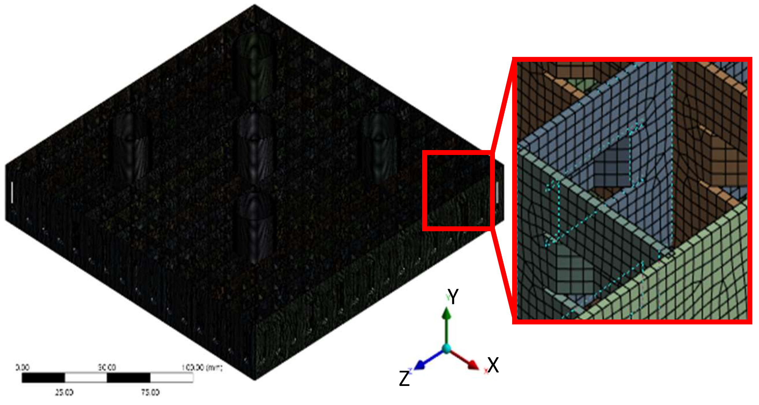
3.1. Development of FEA Model
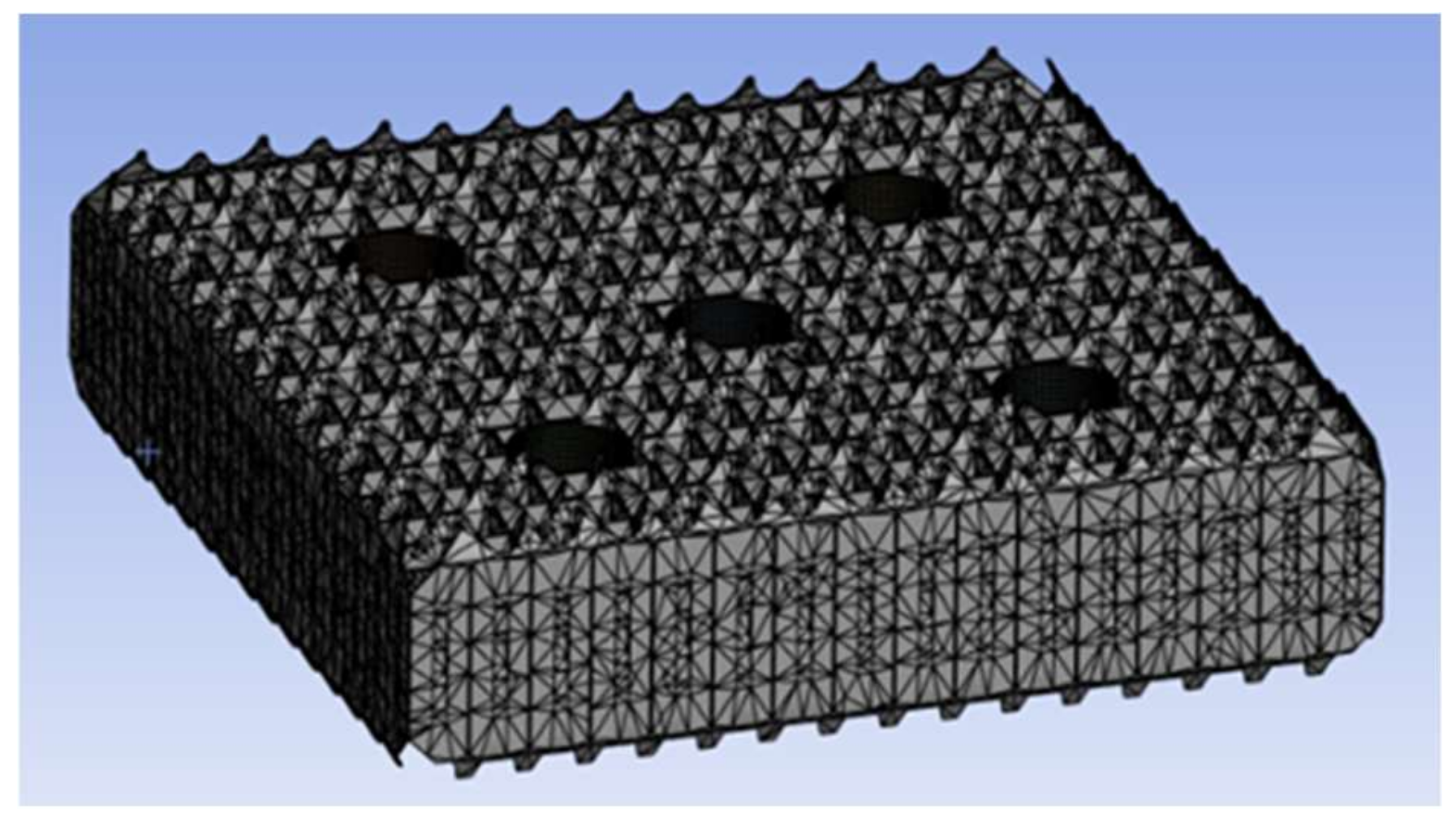
For this study, the mid spacer grid was modeled using 3D CAD software, CATIA V5 [14] and ANSYS SpaceClaim 2023R1 [15]. The FEM models was developed based on shell element. The model was then used to perform a static structural analysis, using ANSYS 2023R1.
The detailed model of PLUS7 mid spacer grid was transferred to ANSYS Mechanical to undergo a meshing process. The simplified and meshed models were used to perform a structural analysis for square and shear loadings for the room, core inlet, and core outlet temperatures. The process flow of the methodology is shown in Figure 5. For the analysis, the collection of material data is important due to the nature of a high temperature environment, i.e., around 290~335 °C. A more detailed description is given in Section 3.4. The modeling-related issues are explained in Section 3.2. Boundary conditions are explained in Section 3.3.
In order to reduce the problem of size, i.e., a lower number of elements and nodes than in the original geometry, the spacer grid geometry was simplified; for example, complicated corners were simplified, and unnecessary features, such as the mixing vane, were removed. Figure 6 shows a simplified model in a symmetrical condition. The simplification takes advantage of symmetry and the removal of the mixing vane and straightening curved boundaries, and converting 3D solid model to 3D surface model. The arrows shown in Figure 6 explaines these steps.

3.2. Meshing

For the reduced 3D shell model, the meshing method was set to quadrilateral mesh method with 0.35 mm element size and the resulting mesh is shown in Figure 7. The model showed 1.06 million nodes and and 0.99 million elements.
Using the surface model shown in Figure 6, mesh refinement was performed and develop a full 3D shell mesh of the model. A further reducing of element size did not produce a useful model that could be used for our analysis. In some cases, the mesh created did not perform well in the analysis due to the poor mesh quality.

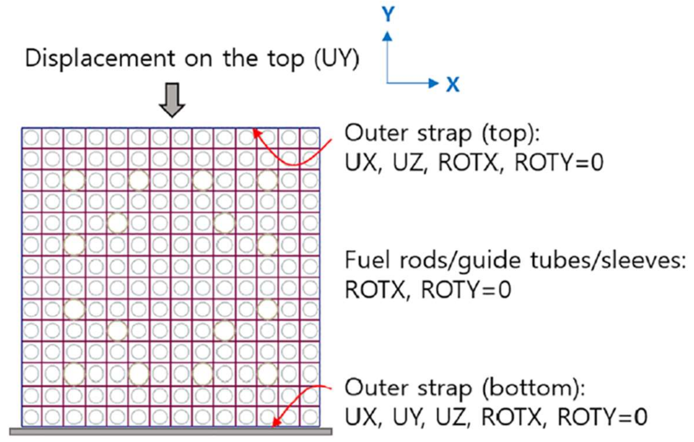
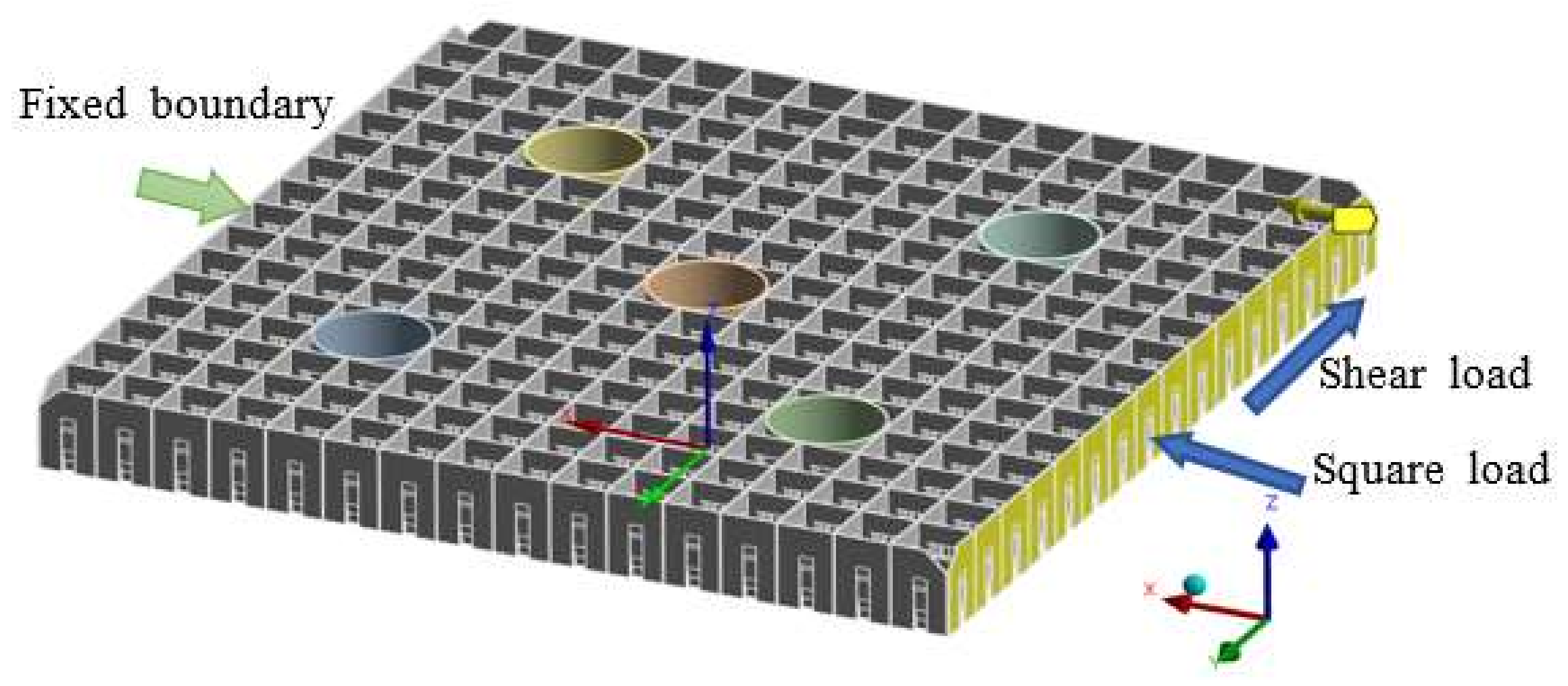
3.3. Boundary Conditions

The fixed support was applied at the surface of the outer wall facing +X direction of each model. The displacement load was applied at the surface facing the −X direction. Figure 8 shows the fixed boundary surface on the left side and square load and shear load on the right side of the x-axis.
For the square load, we applied displacement loads of various magnitude, from 0.2 mm up to 10 mm, toward the +X direction, while for the shear load, we applied displacement loads on the same surface with the square load, but with a magnitude from 0.5 mm up to 20 mm toward the +Y direction. The image of assigned boundary conditions is as shown in Figure 8.

3.4. Zircaloy Material Engineering Data

The PLUS7 fuel assembly’s mid spacer grid uses a type of zirconium alloy, Zircaloy-4, as its material. The material properties of Zr-4 were collected and reviewed to ensure that we obtained valid results for the structural analysis. For the structural analysis of Zircaloy-4, we needed a density that accounted for the weight, thermal expansion coefficient, Young’s modulus, and shear modulus. Since we were dealing with a temperature range of 290~335 °C, obtaining these constants was very important.
MATPRO is one of the well-known and main sources of these material properties [16]. For temperatures under 1090 K, the equations and parameters are as shown below. The density of Zircaloy-4 given in Equation (1) is constant throughout a temperature range of 20~335 °C. The thermal expansion coefficient is given in Equation (2), and it is the linear function of absolute temperature. Young’s modulus and the shear modulus are given in Equations (3) and (4), and they are a function of absolute temperature, function K1 and K2, which, in turn, function as other constants.
Density ,   ρ = 6.55 × 10 3   kg m 3
Thermal   expansion ,   ε = 4.95 × 10 6 T 1.485 × 10 3
Young s   modulus ,   E = 1.088 × 10 11 5.475 × 10 7 · T + K 1 + K 2 K 3 P a
Shear   modulus ,   G = 4.04 × 10 4 2.168 × 10 7 · T + K 1 + K 2 K 3 P a
where
T = t e m p e r a t u r e ,   K K 1 = 6.61 × 10 11 + 5.912 × 10 8 · T = o x y g e n   c o n t e n t   k g   o x y g e n k g   Z i r c a l o y K 2 = 2.6 × 10 10 · C W C W = c o l d   w o r k ,   u n i t l e s s   r a t i o   o f   a r e a K 3 = 0.88 + 0.12 e Φ 10 25 Φ = f a s t   n e u t r o n   f l u e n c e   n / m 2
The constants K1 and K2 are functions of the oxygen content, sold work ratio, and fast neutron fluence of Zircaloy, and they are referred to here from the MATPRO database. Zircaloy, as with any other materials, behaves differently according to the temperature. Due to this fact, we conducted each analysis for three different temperatures, which are room temperature at 21 °C, core inlet temperature at 290 °C, and core outlet temperature at 325 °C.
Oh [17] published the coefficient of thermal expansion for zirconium, and IAEA-TECDOC-949 [18] published the properties for materials used in water-cooled reactors.
For Young’s modulus and shear modulus, parameters such as the fast neutron influence, cold work constant, and oxygen content were considered by utilizing the formula by Geelhood [19] and Siefken et al. [16].
The following constants were used for the analysis.
Oxygen   constant :   = 352   p p m
Cold   work   constant :   C W = 4.17 × 10 5
Fast   neutron   fluence :   Φ = 11.4 × 10 26   n m 2
The shear and elastic modulus of Poisson’s ratio were computed by applying these parameters. The results are presented in Table 1.

4. Results and Discussions

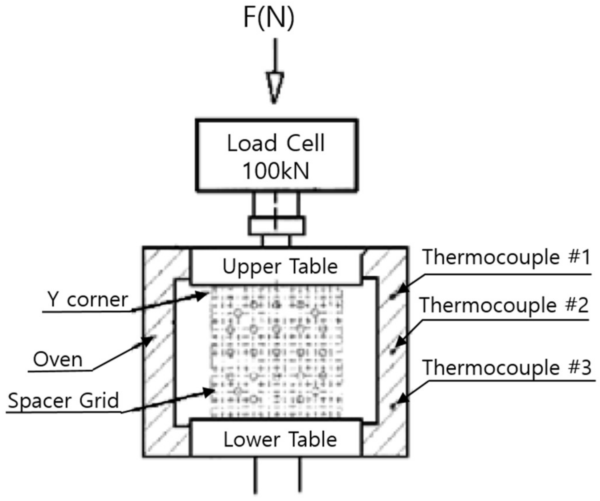
4.1. Review of Spacer Grid Test Results

Notable research on the nuclear fuel spacer grid was performed by the Kore Nuclear Fuel Co. (KNF). They carried out fuel-improvement research, including mechanical integrity, core neutronics, and thermal hydraulics. One of these activities was presented by Yoo [5]. They developed an FEA of a spacer grid mechanical model and compared the results with those of matching static and dynamic tests [5].
In this study, we conducted a generalized structural integrity assessment, using square and shear load on shell models for room, core inlet, and core outlet temperatures.

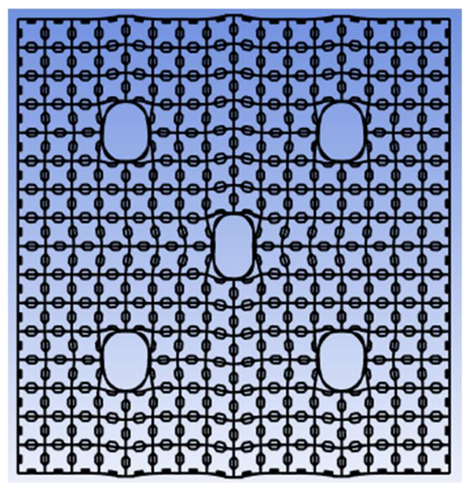
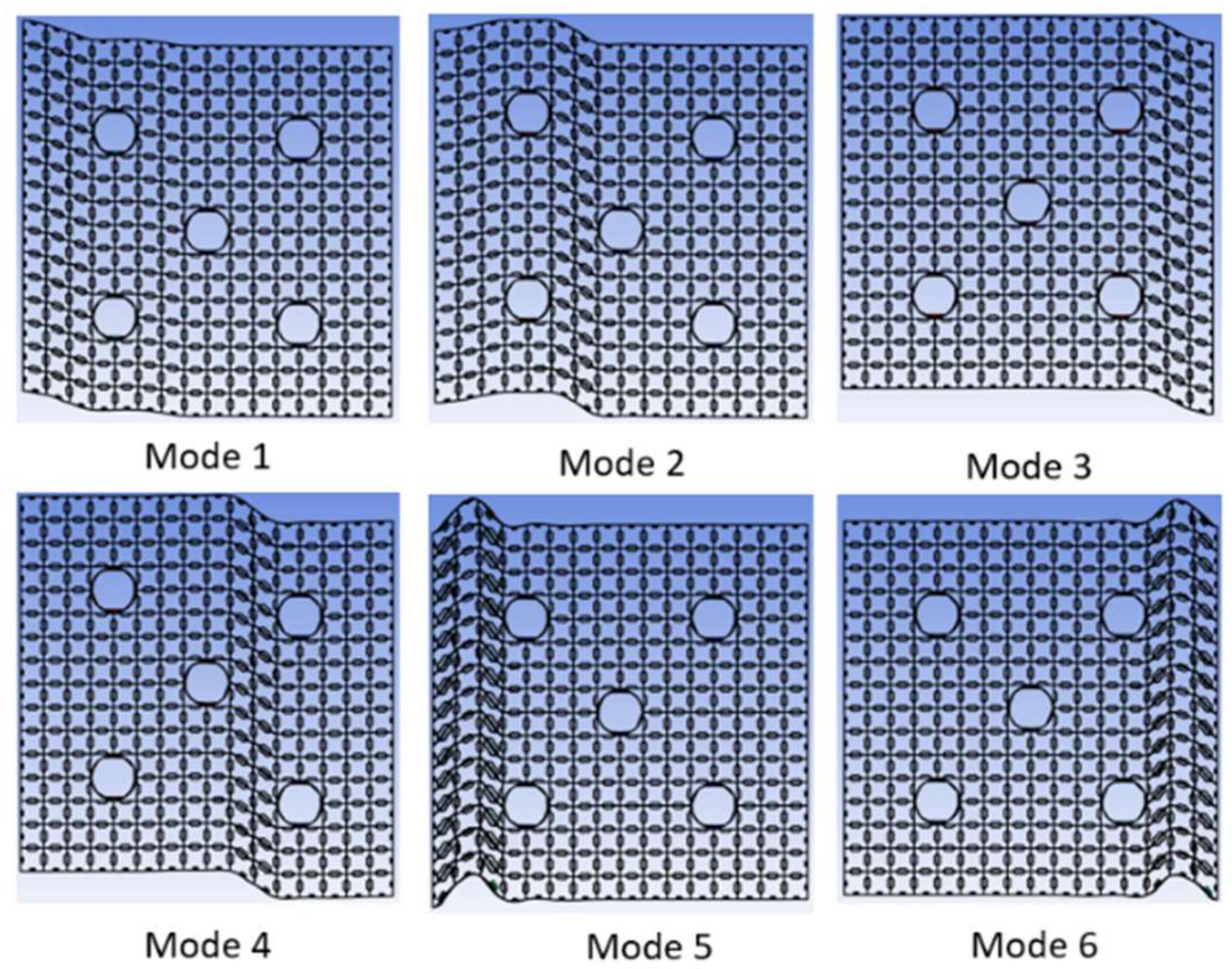
4.2. FEA Results of the Reduced Spacer Grid Models

The maximum deformation patterns of the 3D shell model after displacement loads are shown in Figure 9 for the square load, and in Figure 10 for the shear load. From Figure 9, we can see that the CEA guide tubes are deformed as the square load presses them. Also, long spacer grid plates deform around the guide tube location that have a wiggly deformation shape at the top and bottom spacer grid plates. Figure 9 shows the shear deformation of the spacer grid. In this case, the CEA guide tubes deform less than in the square load case; hence, the deformation shape is smoother than that of the square load case.
The force reactions, when subjected to square and shear displacement load, in all temperatures, are shown in Table 2 and Table 3. The load–deflection data of square loads show linear relations for all cases, room temperature, core inlet temperature, and core outlet temperature. For the square load case, the stiffness values at 21 °C, 290 °C, and 335 °C are 48.7 kN/mm, 41.1 kN/mm, and 40.2 kN/mm, respectively. And that for the shear load cases, the stiffness values are 118 N/mm, 102 N/mm, and 100 N/mm. The ratio of square stiffness to shear stiffness is around 400. This result is significant in that the spacer grid is very weak against a shear load.
The buckling analyses produced 6 different buckling modes, and are shown in Figure 11 and the buckling loads are shown in Table 4. It is interesting that from the load-deflection data given in Table 2 and Table 3, buckling point is not clear, however from Table 4, buckling occurs at around 3.4 mm displacement of square load.
One of the main uses of the results is developing a simplified model of a spacer grid, using square direction stiffness and shear direction stiffness. Furthermore, we can develop a very simple fuel assembly model using the equivalent stiffness obtained in this research.
It is also very important to point out that most of the fuel assembly experiments or analyses did not perform a shear deformation test or analysis. We showed, in this research, that the spacer grid is very weak in shear load; hence, shear load is very important to include in the test or analysis of fuel assembly.

5. Conclusions and Further Considerations

Designs of nuclear fuel assemblies are demanded to ensure reliable structural integrity for all operating conditions. Especially after the Fukushima accident, a large external load toward NPP and on the reactor is of great concern, and so we need to find a way to simulate beyond a design basis load, such as the seismic load. The seismic load can come in from any direction to the reactor core and upon individual fuel assembly in the core. It is well known that the spacer grid is one of the bottlenecks of the structural integrity of fuel assembly and the reactor core.
In this regard, our research showed two important aspects of fuel assembly: structural stiffness and core integrity. One is to obtain the stiffness values of the spacer grid in the square direction and shear direction that can be used to model a simplified fuel assembly model for a seismic analysis. The other is that a very weak shear stiffness of the spacer grid raises concern about structural rigidity and integrity for a heavy load, such as a seismic load.
As for future considerations, including fuel clad and pellets in the model is needed for a better representation of fuel assembly stiffness. Also, developing a simplified fuel assembly model is the next stage of research that can be used for a full core dynamic analysis. A 3D full core dynamic analysis model has not been developed, so the research result we presented in this paper is an important step toward developing a full core dynamic analysis model.

Author Contributions

N.H.A.: Computer run and draft writing. I.N.: Conceptualization, funding, checking analysis method and result, final draft writing and revision. All authors have read and agreed to the published version of the manuscript.

Funding

This research was supported by the National Research Fund, NRF-2022M2C7A1A02064364, Republic of Korea.

Data Availability Statement

Not applicable.

Acknowledgments

This work was supported by the 2023 Research Fund of the KEPCO International Nuclear Graduate School (KINGS), Republic of Korea.

Conflicts of Interest

The authors declare no conflict of interest.

References

  1. Subhan, M.; Namgung, I. Development of nuclear fuel assembly 3D reduced model and modal analysis. Ann. Nucl. Energy 2023, 181, 109561. [Google Scholar] [CrossRef]
  2. ASME. ASME Boiler and Pressure Vessel Code, Section III, Non-Mandatory Appendix F, Rules for Evaluation of Service Loadings with Level D Service Limits; American Society of Mechanical Engineers: New York, NY, USA, 2021. [Google Scholar]
  3. Namgung, I. An investigation of structural strength of PWR fuel assembly spacer grid with fuel rod clad. Ann. Nucl. Energy 2024, 195, 110124. [Google Scholar]
  4. Song, K.N.; Lee, S.B.; Shin, M.K.; Lee, J.J.; Park, G.J. New spacer grid to enhance mechanical/structural performance. Nucl. Sci. Technol. 2010, 47, 295–303. [Google Scholar] [CrossRef]
  5. Yoo, Y.; Kim, K.; Eom, K.; Lee, S. Finite element analysis of the mechanical behavior of a nuclear fuel assembly spacer grid. Nucl. Eng. Des. 2019, 352, 110179. [Google Scholar] [CrossRef]
  6. IAEA. Structural behavior of fuel assemblies for water cooled reactors. In Proceedings of the Technical Meeting, Cadarache, France, 22–26 November 2004; IAEA-TECDOC-1454. IAEA: Vienna, Austria, 2004. [Google Scholar]
  7. Areva. PWR Fuel Assembly Structural Response to Externally Applied Dynamic Excitations; Topical Report to NRC; AREVA Inc.: Columbia, MD, USA, 2015. [Google Scholar]
  8. Yoon, K.H.; Heo, S.P.; Song, K.N.; Jung, Y.H. Dynamic impact analysis of the grid structure using multi-point constraint (MPC) equation under the lateral impact load. Comput. Struct. 2004, 82, 2221–2228. [Google Scholar] [CrossRef]
  9. Shin, M.K.; Lee, H.A.; Lee, J.J.; Song, K.N.; Park, G.J. Optimization of a nuclear fuel spacer grid spring using homology constraints. Nucl. Eng. Des. 2008, 238, 2624–2634. [Google Scholar] [CrossRef]
  10. Schettino, C.F.M.; Gouvêa, J.P.; Medeiros, N. Analysis of spacer grid compression strength and fuel assembly structural behavior. Nucl. Eng. Des. 2013, 260, 93–103. [Google Scholar] [CrossRef]
  11. Kim, K.T.; Suh, J.M. Development of an advanced PWR fuel for OPR1000s in Korea. Nucl. Eng. Des. 2008, 238, 2606–2613. [Google Scholar] [CrossRef]
  12. Yoo, Y.; Kim, J.; Park, J.; Kim, H. Development of nuclear fuel assembly finite element model for mechanical integrity evaluation. Nucl. Eng. Des. 2023, 413, 112523. [Google Scholar] [CrossRef]
  13. Choi, Y.; Park, J.B.; Lee, S.J.; Park, N.C.; Park, Y.P.; Kim, J.S.; Roh, W.J. Seismic analysis of the APR 1400 reactor vessel internals using the model reduction method. J. Nucl. Sci. Technol. 2016, 53, 1701–1714. [Google Scholar] [CrossRef]
  14. CATIA, 3D computer aided design software, CATIA V.5. Release 2023.
  15. ANSYS. Mechanical Properties, Data Compiled by the Granta Design Team at ANSYS, Incorporating Various Sources Including JAHM and MagWeb; ANSYS R2 Version; ANSYS, Inc.: Canonsburg, PA, USA, 2023. [Google Scholar]
  16. Siefken, L.J.; Coryell, E.W.; Harvego, E.A.; Hohorst, J.K. MATPRO—A Library of Materials Properties for Light-Water-Reactor Accident Analysis; Idaho National Engineering and Environmental Laboratory for NRC: Idaho Falls, ID, USA, 2001. [Google Scholar]
  17. Oh, Y.J.; Baek, J.H.; Lee, S.H.; Jeong, Y.H. The Measurement of Basic Thermal and Mechanical Properties of HANA Cladding Tubes. In Proceedings of the KNS Fall Conference, Busan, Republic of Korea, 27–28 October 2005. [Google Scholar]
  18. IAEA. Thermophysical Properties of Materials for Water Cooled Reactors; IAEA-TECDOC-949; IAEA: Vienna, Austria, 1997. [Google Scholar]
  19. Geelhood, K.J.; Neyer, C.E.; Luscher, W.G. PNNL Stress/Strain Correlation for Zircaloy; Pacific North-West National Laboratory Report PNNL-17700; U.S. DOE: Washington, DC, USA, 2008.
Figure 1. Static compression model of spacer grid (Yoo [5]).
Energies 17 00458 g001
Figure 2. Multiple grid mechanical integrity test (Yoo et al. [12]).
Energies 17 00458 g002
Figure 3. Grid compression test setup (Yvon et al. [6]).
Energies 17 00458 g003
Figure 4. Full spacer grid mesh.
Energies 17 00458 g004
Figure 5. Process flow of the spacer grid FEA simulation.
Energies 17 00458 g005
Figure 6. Reduction from full spacer grid to reduced 3D shell model of the spacer grid.
Energies 17 00458 g006
Figure 7. A 3D shell meshing of the spacer grid.
Energies 17 00458 g007
Figure 8. Boundary conditions of the spacer grid model for the FEA simulation.
Energies 17 00458 g008
Figure 9. Total deformation of shell model with 10 mm square displacement load.
Energies 17 00458 g009
Figure 10. Total deformation of shell model with 20 mm shear displacement load.
Energies 17 00458 g010
Figure 11. Six buckling modes of shell model.
Energies 17 00458 g011
Table 1. Mechanical properties of Zircaloy-4.
Temp. (°C)Young’s Modulus (GPa)Shear Modulus (GPa)Poisson’s Ratio
21105.67838.9990.355
29089.00532.4360.372
32586.83631.5770.375
Table 2. Load-deformation for square displacement.
Input Square Disp. (mm)Reaction Force (kN)
21 °C290 °C325 °C
0.28 7 7
0.520 17 17
140 34 33
1.560 51 50
280 68 66
2.5101 85 83
3121 102 99
3.5141 119 116
4161 136 132
4.5181 153 149
5201 170 166
5.5221 187 182
6241 204 199
6.5261 220 215
7281 237 232
7.5302 254 248
8322 271 265
8.5342 288 281
9362 305 298
9.5382 322 314
10402 339 331
Table 3. Load-deformation curve for shear displacement.
Input Shear Disp. (mm)Reaction Force (N)
21 °C290 °C325 °C
0.545 39 38
191 77 75
2182 154 151
3272 232 226
4363 309 302
5454 386 377
6545 463 453
7636 540 528
8726 618 604
9 817 695 679
10908 772 755
11999 849 830
12 1090 926 905
131180 1004 981
141271 1081 1056
15 1362 1158 1132
161453 1235 1207
17 1544 1312 1283
181634 1390 1358
191725 1467 1434
201816 1544 1509
Table 4. Table of buckling load of shell model at each temperature.
ModeForce (kN)
21 °C290 °C325 °C
114.512.412.1
214.612.412.1
315.212.912.6
415.313.012.7
518.315.615.2
618.515.715.4
Disclaimer/Publisher’s Note: The statements, opinions and data contained in all publications are solely those of the individual author(s) and contributor(s) and not of MDPI and/or the editor(s). MDPI and/or the editor(s) disclaim responsibility for any injury to people or property resulting from any ideas, methods, instructions or products referred to in the content.

