Review

Asymmetric Operation of Power Networks, State of the Art, Challenges, and Opportunities

by
Ansar Berdygozhin
and
David Campos-Gaona
*,†
Electronic and Electrical Engineering Department, University of Strathclyde, 16 Richmond St, Glasgow G1 1XQ, UK
*
Author to whom correspondence should be addressed.
These authors contributed equally to this work.
Energies 2024, 17(20), 5021; https://doi.org/10.3390/en17205021
Submission received: 30 August 2024 / Revised: 3 October 2024 / Accepted: 7 October 2024 / Published: 10 October 2024
(This article belongs to the Special Issue Energy, Electrical and Power Engineering 2024)

Abstract

:
The asymmetric operation is a method that allows High and Extra-High Voltage (HV, EHV) power lines to function with one or two phases open. With the increasing share of Renewable Energy Sources (RES) in National Power Systems (NPS), they are becoming more volatile and less reliable due to decreasing inertia and other issues related to the integration and exploitation of the Inverter-Based Resources (IBR) (decreasing short-circuit ratio, different types of interactions, etc.). On the other hand, phase-to-ground faults are a common cause of tripping off power lines which affects the overall reliability of the power system. Thus, for power systems experiencing a decreasing trend in reliability and robustness, the asymmetrical operation of the power lines may enhance them. In this way, this article reviews the state of the art and new developments in the academic landscape regarding asymmetrical operation. The review is not, however, limited to HV and EHV systems, so it examines cases of asymmetric operation in Low and Medium Voltages (LV, MV) as well. The challenges and opportunities that this unique mode of operation imposes on power networks are also presented, providing a fresh reference for researchers looking to enter this topic.

1. Introduction

The origins of AC power transmission can be traced to 1886, when William Stanley demonstrated an electrical system with a 2% loss, operating at 500 V, in Great Barrington, Massachusetts, successfully transmitting power over a distance of 4000 feet [1]. This system utilized single-phase transmission and so inherently was asymmetrical. In 1895, Westinghouse Electric Corporation initiated the construction of 90°-shifted two-phase generators for the Niagara Falls power plant. The generated power was transmitted to Buffalo, NY, via an 11 kV, 25-mile transmission line at 25 Hz [2]. By this time, the symmetrical three-phase system had already been developed and showcased at the 1891 Frankfurt International Electrotechnical Exhibition. However, the two-phase system was initially favored by the Niagara Falls power plant owners due to the lack of clarity regarding the relative advantages of the two-phase versus three-phase systems at that time. It was soon recognized that the three-phase systems offered superior efficiency for AC machinery and power transmission, leading to their widespread adoption—a trend that continues today.
Moving to the present day, driven by the global trend towards zero-emission targets, the replacement of fossil-fuel-based generation with large-scale converter-interfaced Renewable Energy Sources (RES) [3] has altered the decades-long dominance of Synchronous Generators (SG), introducing new mechanisms for controlling the electric power supply. In this regard, a substantial body of research and numerous ideas have focused on the diverse applications of Inverter-Based Resources (IBRs) to improve the reliability, stability, and efficiency of power systems. From a modern power network perspective, IBRs providing ancillary services as Flexible Alternating Current Transmission Systems (FACTS) will increasingly be required in the future to compensate decreasing number of SGs. There are different types of FACTS, which can be categorized by their connection type (series, shunt, or a combination of the two), type of semiconductors, power electronic topology, and control methods.
As will be discussed in this review article, the reliability and flexibility provided by IBRs and FACTs are not limited to symmetrical three-phase systems but can also be applied to provide asymmetrical operation of power lines. However, the applicability of these devices to the asymmetrical operation of power networks has not been as widely investigated as its three-phase counterpart. Because of this, this review seeks to highlight the relevance of studying asymmetrical networks in the context of modern inverter-interfaced power systems and their energy trilemma (i.e., archiving Energy Security, Energy Sustainability, and Energy Affordability). The objective of this literature review is to explore key questions such as: Why is the asymmetrical operation of power networks important? What has been achieved in this area in the past? What challenges have arisen? And what opportunities exist in modern converter-interface networks to tackle these challenges? This review paper consists of 6 sections. Section 2 presents the definitions needed to appreciate the operation and need for asymmetrical networks. Section 3 summarizes the historical approaches used to operate asymmetrical power networks. Section 4 provides a review of the latest literature dealing with the asymmetrical operation of networks. Section 5 discusses the challenges, gaps, and opportunities in the research landscape. Finally, Section 6 presents the conclusions of this literature review.

2. Definitions

2.1. Symmetry in Power Systems

In terms of theory, the symmetrical balanced polyphase system phasors are mathematically described by the phasors’ root of unity on the complex plain. The derivation of the formula to calculate the exact coordinates of phasors comes from the expression
1 = z k n , z C , n N , k = 0 , 1 , , n 1 ,
which by De Moivre’s formula becomes [4]
z k = c o s ( 2 π k n ) j s i n ( 2 π k n ) .
here, the sign of the imaginary part is changed to ‘-’ from the original formula (this is to adhere to the definition that positive-sequence phasors rotate counterclockwise), and n is the overall number of phases or roots, k is the k-th phase or root, and z k is the phasor’s coordinate on the complex plain. The first phase or a phase phasor will always align with the positive real axis. The other phasors will spread equally according to Equation (2).
Equation (2) provides symmetrical phasor vectors with unity length. Figure 1 shows balanced, symmetrical polyphase systems with three and five phasors on the complex plain as an example. In this way, for Figure 1a the phasors’ complex coordinates turn to be:
z 0 = A = 1 + j 0 , z 1 = B = 1 2 j 3 2 , z 2 = C = 1 2 + j 3 2 ;
and for Figure 1b, the phasors’ complex coordinates turn out to be:
z 0 = A = 1 + j 0 , z 1 = B = 5 1 4 j 10 + 2 5 4 , z 2 = C = 5 1 4 j 10 2 5 4 , z 3 = D = 5 1 4 + j 10 2 5 4 , z 4 = E = 5 1 4 + j 10 + 2 5 4 .
The general criteria of the symmetrically balanced operation in terms of sequence components requires that:
I ( 2 ) = 0 I ( 0 ) = 0 ,
and
V ( 2 ) = 0 V ( 0 ) = 0 .
where superscripts (2) and (0) refer to the negative- and zero-sequences, respectively. If the sequence components of a power line are considered, the criteria must be met at both ends. Moreover, these criteria apply to both one-phase and multi-phase systems, yet one-phase systems are asymmetrical a priory. For two-phase systems, the phase shift between voltage phasors must be 180° to achieve symmetry. Since phase-to-phase or line-to-line voltage is calculated as the difference between two phasors, the magnitude of the phase-to-phase voltage in a two-phase symmetrical balanced system will be doubled. Thus, these systems are impractical due to the increasing insulation requirements.
If at least one of the left-hand side terms in Equations (3) and (4) differs from zero, the system is considered unbalanced. If an unbalanced power line operates with one or two phases open, it functions under asymmetrical conditions. The term “asymmetrical operation” of power lines has been present in the literature since 1999, referring to the pioneering works of A. Sana et al. in this field [5,6]. There are, however, more criteria than Equations (3) and (4), which are related to power quality at the generation unit Point of Common Coupling (PCC) and load. These other criteria are, however, beyond the scope of this review paper. Furthermore, when the asymmetrical operation of a power line is considered in [7,8], the voltages at two extremities are assumed constant and balanced symmetrical, as they are dictated by the power flow. This assumption is true for most HV and especially for Extra-High Voltage/Ultra-High Voltage (EHV/UHV, 230 kV and above) transmission power lines, but may not be the for low-voltage (i.e., distribution) networks. The cases presented in this review paper consider constant symmetrical voltages at the extremities of the transmission line. As such, the methodologies discussed and presented here are more applicable to EHV/UHV networks.

2.2. Needs for Asymmetric Operation of Power Lines

Since single-phase-to-ground faults are among the most common causes of power line tripping, the asymmetric operation of power lines presents a promising solution to enhance system reliability and improve the security of supply. In the event of an open phase, the power line retains approximately two thirds of its rated power transfer capability.
Using real data statistics, the authors in [9] show that for any fault reported in transmission lines, the percentage of single-phase-to-ground faults increases with both voltage levels and the dimensions of the power lines. For example, this percentage is approximately 60% for 220 kV, while for 750 kV, it accounts for 97% of all faults. In contrast, the success rate of Single-Pole Automatic Reclosures (SPAR) decreases at voltage levels above 330 kV, with a 72% success rate for 330 kV and 52% for 750 kV. Thus, for Extra-High Voltage (EHV) and Ultra-High Voltage (UHV) power lines, there is roughly a 50% chance of recovery, or in 50% of cases, tripping one phase leads to the tripping of the entire power line. The authors of [9] attribute unsuccessful SPAR attempts to a significant reduction in specific trippings as voltage levels increase, making faults that cannot be mitigated by SPAR more common. Thus, the implementation of asymmetric operation might significantly improve the situation. If SPAR cannot restore the phase and asymmetrical operation is used, the phase can be opened, allowing the power line to continue functioning with a reduced power flow (if energy storages are not used). Otherwise, subsequent contingencies, in some cases, could lead to Power System (PS) splits, load shedding, and blackouts. This scenario could become a reality for countries with long (>240 km), unreserved or insufficiently reserved transmission lines, such as Brazil, Australia, Kazakhstan, etc., where electric power is delivered by one or a few lines from distant generation stations to consumption regions. Moreover, all the aforementioned countries are committed to increasing the share of RES in their National Power Systems (NPSs).
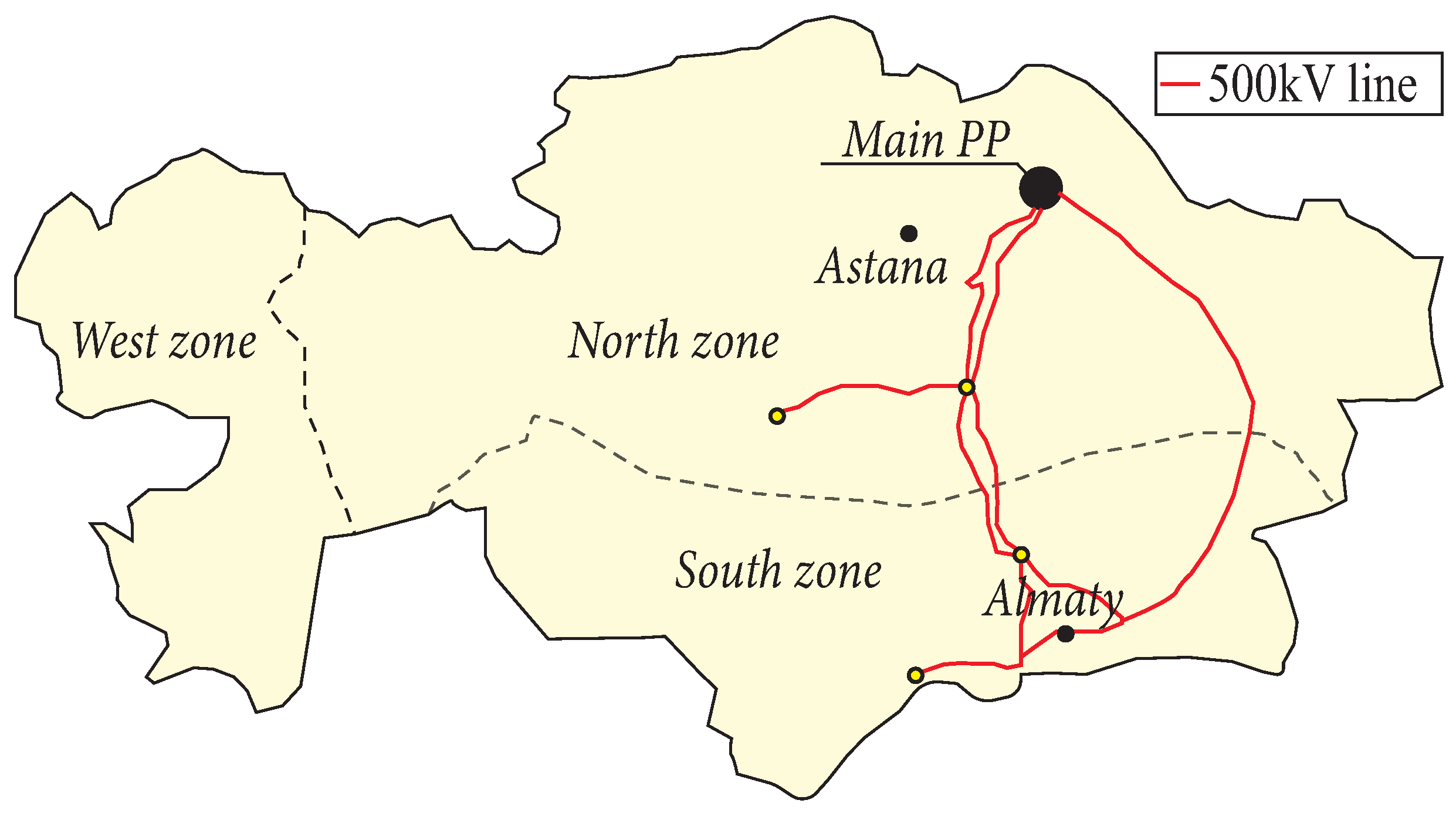
For example, Kazakhstan has committed to increasing the share of renewable energy sources (RES) from the current 6% to 10% by 2030, with a long-term target of 50% by 2050 [10]. To attain these goals, the Kazakhstan power grid requires new levels of flexibility, robustness, and reliability. However, its capability to adopt RES is affected by its current network topology. The backbone of Kazakhstan’s NPS is the North-South electric power transmission network, which primarily transfers electricity from the main power plants (PP) located in the North zone to customers in the South zone. This network consists of three 500 kV transmission lines spanning over 1000 km. Two of these lines follow roughly in one corridor through Central Kazakhstan, while the third goes through East Kazakhstan, as shown in Figure 2. Despite the redundancy provided by these lines, the South zone continues to experience significant power deficits, making the NPS highly vulnerable to the loss of any of these critical transmission lines. This vulnerability is further compounded by the strict frequency deviation limit (±10 mHz, dead zone) imposed by the Russian System Operator (SO) [11].

2.3. Security of Supply Enhancement by Asymmetrical Operation of Transmission Lines

In general, the asymmetric operation of the generic three-phase power line is based on suppressing negative- and zero-sequence currents at both extremities, which appear when one phase or two phases are open. This allows the retention of some power transfer capabilities without subjecting the sending and receiving ends to asymmetries. Therefore, the electric networks ‘before’ and ‘after’ the power line ‘see’ normal three-phase symmetrical operation. As mentioned, asymmetrical operation with two open phases could be possible. However, the probability of the faulted two phases is lower than a single-phase fault, and the probability of the second phase loss, when two phases are operational, is low as well [12].
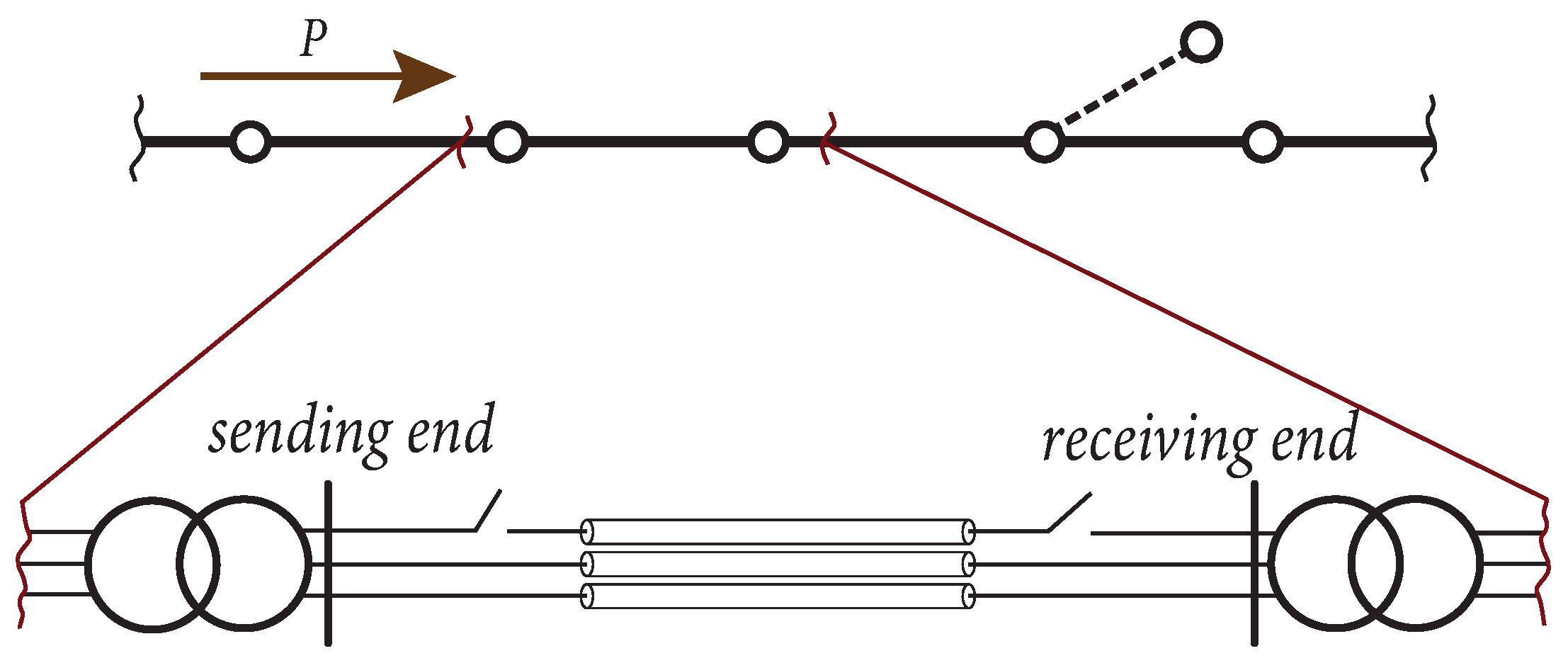
Figure 3 illustrates the principles of the power line asymmetric operation using filters at the sending and receiving ends. If filters are based on power electronics, they can be used versatile to suppress both zero- and negative-sequence currents, whereas if passive-element filters are used, separate devices are needed for each sequence component. The zero-sequence current flow appears between the ground connection points of the filters when it is mitigated. A situation when electric power transmission consists of a few series power lines, possible branches (dashed line), and its element (one power line) is shown in Figure 4. In this situation, one phase opening traditionally leads to the loss of the entire power transmission. However, the asymmetric operation allows the power line to function with the open phase(s) and maintain the flow of electric power. Another scenario where the asymmetrical operation is beneficial occurs when a power transmission has a double circuit or a limited number of parallel lines. In this context, the asymmetric operation enhances the share of power flow among the power lines and increases the overall reliability of the electric power transmission system, therefore improving its security of supply [7].
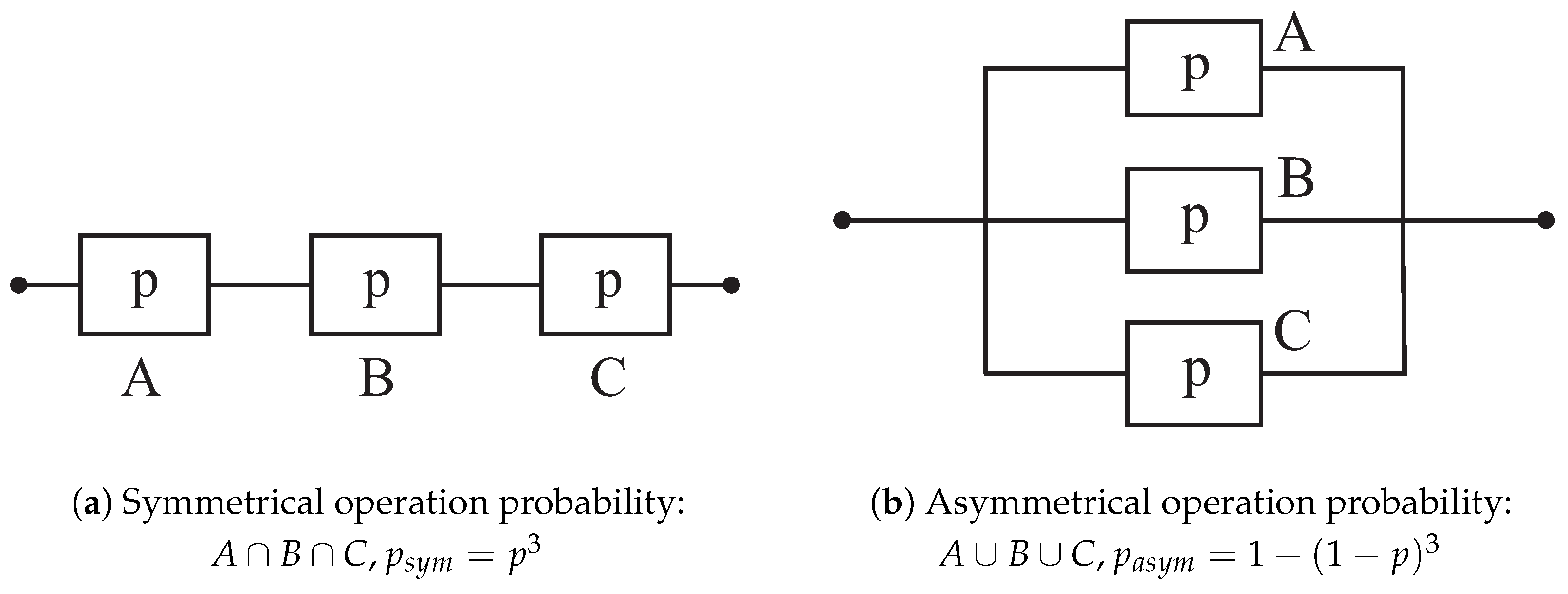
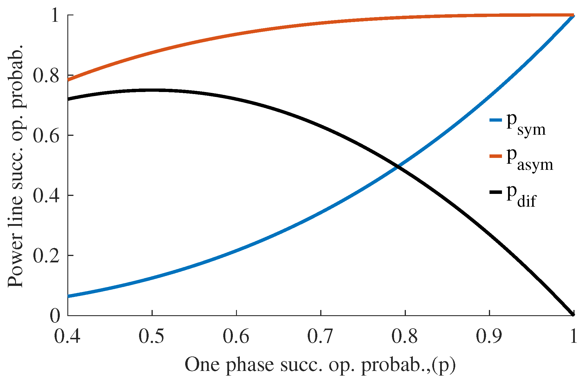
The increase of the PS reliability with asymmetric operation employment comes from the power lines’ higher successful operational probability. Figure 5a shows the logical scheme and formula of the power line symmetrical operation, where p—is the one phase successful operation probability. As such, the successful operation of the entire power line is calculated as n (number of elements) power of p. In the case when electric power transmission consists of a few series of power lines, as aforementioned, the overall successful probability decreases substantially. For the asymmetric operation of the power line, Figure 5b shows the logic scheme and formula to calculate its successful operation [7]. Figure 6 represents curves of the successful operation probability in symmetrical and asymmetrical operation with a range of p from 0.4 to 1, and their difference, p d i f . Taking into account the SPAR percentage for EHV/UHV Overhead Power Lines (OPL) is about 50%, asymmetrical operation provides significant reliability in comparison to traditional symmetrical operation.

3. Historical Approaches to Power Line Asymmetrical Operation

3.1. Conceptual Approach

As a conceptual approach, A. Sana et al. employ the idea that each phase of a three-phase power transmission line can be considered as a separate circuit [7,8,12]. This approach allows the implementation of passive or PE-based filters and zero-sequence filtering directly by calculating sequence components at two extremities when one or two phases are open. However, the approach does not take into account electromagnetic interactions between the opened phase/es, the working phase, and the return current. The working phase/es induce/es current into the open phase/es, and, moreover, the open phase/es will still have charging current/s product of pure electromagnetic interaction with the rest of the healthy phases of the line. It is suggested by the aforementioned research works to realize zero-sequence current flow through the shield wire or grounding wire, which is used for thunder strike protection in EHV/UHV OPL. However, a system like this needs to be investigated in terms of electromagnetic interactions. It is evident that this system cannot be represented by a 2-port network, with equal A, B, C, D parameters for each phase (which is used for transposed power line with symmetrical parameters modeled as π -equivalent circuit) [14].
Another way of organizing the return path is proposed in [15]. The method is based on the approach that has been used in practice by HVDC power lines when the return path is through the earthing electrodes located distantly (10–45 km) from the power substation. Due to the lower resistivity of deeper ground layers, deep electrodes are more effective [16,17]. In addition, the proper design and geometry of the electrodes reduce the risk of electrical hazards. Moreover, using this technology for AC is corroborated by the fact that HVDC electrodes, according to CIGRE standard [18], must be able to carry transient currents of equal magnitude to that of the HVDC power line. For instance, a sample calculation example in [18] shows that the amplitude of the transient currents in the HVDC electrodes is larger than the amplitude of the zero-sequence currents in asymmetrical operation for a 500 kV power line load at 900 MW Surge Impedance Loading (SIL).
The generic model of a balanced power line, with sequence components taken into account, is provided in Appendix A. The model shows that when sums of phase currents are a non-zero value at the O and O’, the excessive current (zero-sequence current) will start to flow through C g / 2 capacitance. Moreover, if a phase conductor is open at both ends and points O and O’ are not grounded (thus having non-zero potentials), current will start to flow through the opened phase conductor as well. However, the situation is different if, somewhere along the line, the open phase is grounded due to a phase-to-ground fault. In this case, this phase/es will split into two parts, and the charging current will reduce.

3.2. Unbalanced and Asymmetric Operation in Low-Voltage and Distribution Systems

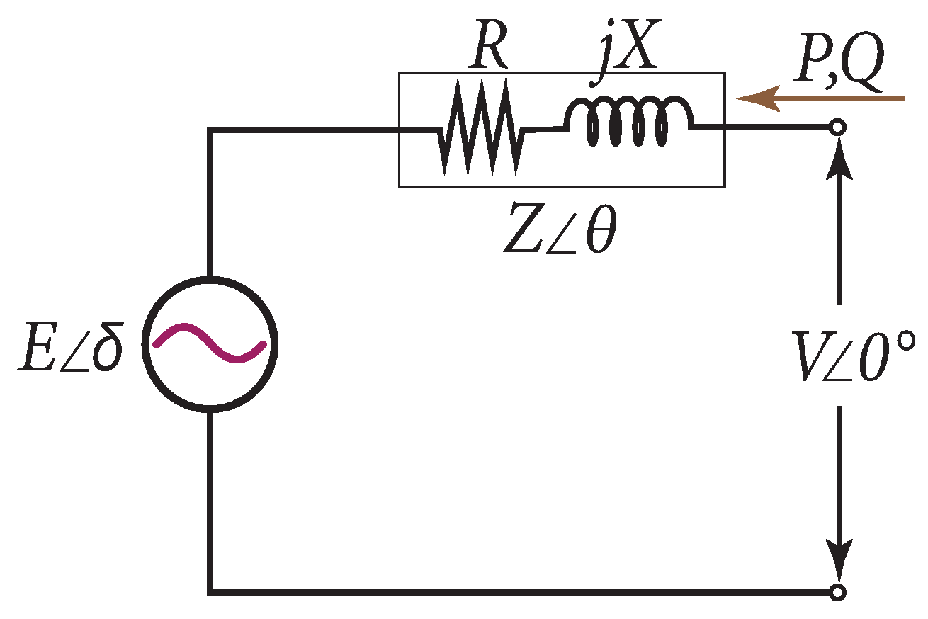
In general, in Low-Voltage (LV) distribution systems, the unbalance of currents and voltages, as well as power quality issues, can be found often. It is so due to connected one-phase linear and non-linear loads, and IBRs (rooftop PV panels, batteries). Moreover, where power electronics are involved either on the generation or consumption (load) side, it inherently injects higher order harmonics [19]. However, if the harmonics are not taken into account, one of the major issues in LV systems is voltage unbalance at various points due to the massive integration of single-phase generation units, which leads to the reverse of active power flow. This is explained by the fact that Distributed Generation (DG) changes the usual passive networks into active ones. Unlike high-voltage systems where X / R ratio is high and so resistance can be neglected, in low-voltage systems, the ratio might be one ( X R ). Moreover, because the voltage level usually is not controlled in LV systems, active power generation changes not only the voltage angle δ ( E δ ) but the voltage levels as well, | E | , | V | . Figure 7 represents one-phase AC voltage source connected to the distribution line, and Formulae (5) and (6) show active and reactive power calculation, P and Q, respectively, when resistance, R, is not neglected. Thus, ref. [20] proposes coordinated and local voltage control using PV panels to mitigate overvoltage issues, as it does not require additional investments. The proposed method combines central and local voltage control, addressing the limitations of each. It overcomes the inability of central control to adapt to operational changes due to communication delays, and it improves the accuracy of local control, which can result in suboptimal reactive power absorption due to non-optimal parameter settings. The influence of DG on distribution systems is considered in [21] using the Canadian rural benchmark. The authors show that using three-phase DG far from the substation reduces the Voltage Unbalance Factor (VUF). For single-phase DG, the maximum DG penetration reached at least 4 times the rated load with a three-phase regulator and 3 times with three single-phase regulators. However, using three single-phase regulators may increase VUF due to varying tap positions across the phases, especially in scenarios with either three-phase or single-phase DG.
P = E V Z c o s ( δ θ ) + R V 2 Z 2
Q = E V Z s i n ( δ θ ) X V 2 Z 2
In general, the devices dedicated to enhancing symmetry and power quality, located at the loads, are Active Power Filters (APF), which can be one-phase as well. The APFs not only balance currents and voltages, but also eliminate harmonics and so improve power quality. For these purposes, different control methods are used. The most spread is approaches based on different power theories (Akagi’s p-q theory [22], special power theory, FBD-Method, IEEE Standard 1459-based Reference Compensation method etc.) and synchronous reference frame-based methods [23].
In distribution voltage levels (2 kV–35 kV), D-STATCOMs are one of the proposed devices to balance voltages and currents, improve power quality, and eliminate voltage flickers that appear when power flow or load changes rapidly [24]. E-STATCOMs are equipped with energy storage which allows the controlling of active power at PCC. This helps to enhance the generation output of RES by making output power more stable [25].
One of the solutions, in case of a lost phase or the desire to minimize investments in MV distribution systems with isolated neutral, is the reconfiguration of transformer windings at both extremities to form Delta connections (if they were not Delta before the fault) as shown in Figure 8. The open Delta connection requires only two transformers/windings at each extremity yet provides symmetry with reduced power transmission (≈57.8%) and overall efficiency, however. Meanwhile, there is no need for additional equipment to suppress negative- and zero-sequence components. This solution has been well known since the early 20th century when two-phase power lines were used [26,27]. There are two main limitations to using open Delta for HV/EHV systems. First, in HV/EHV systems, Y or Star connections of transformers are used as relays on the neutral point to detect single-phase-to-ground faults. Second, a Delta connection of a transformer requires higher electrical insulation due to the higher phase-to-phase voltage compared to phase-to-ground voltage.

3.3. Practically Realized Medium-Voltage (2.4–69 kV) Asymmetric Systems

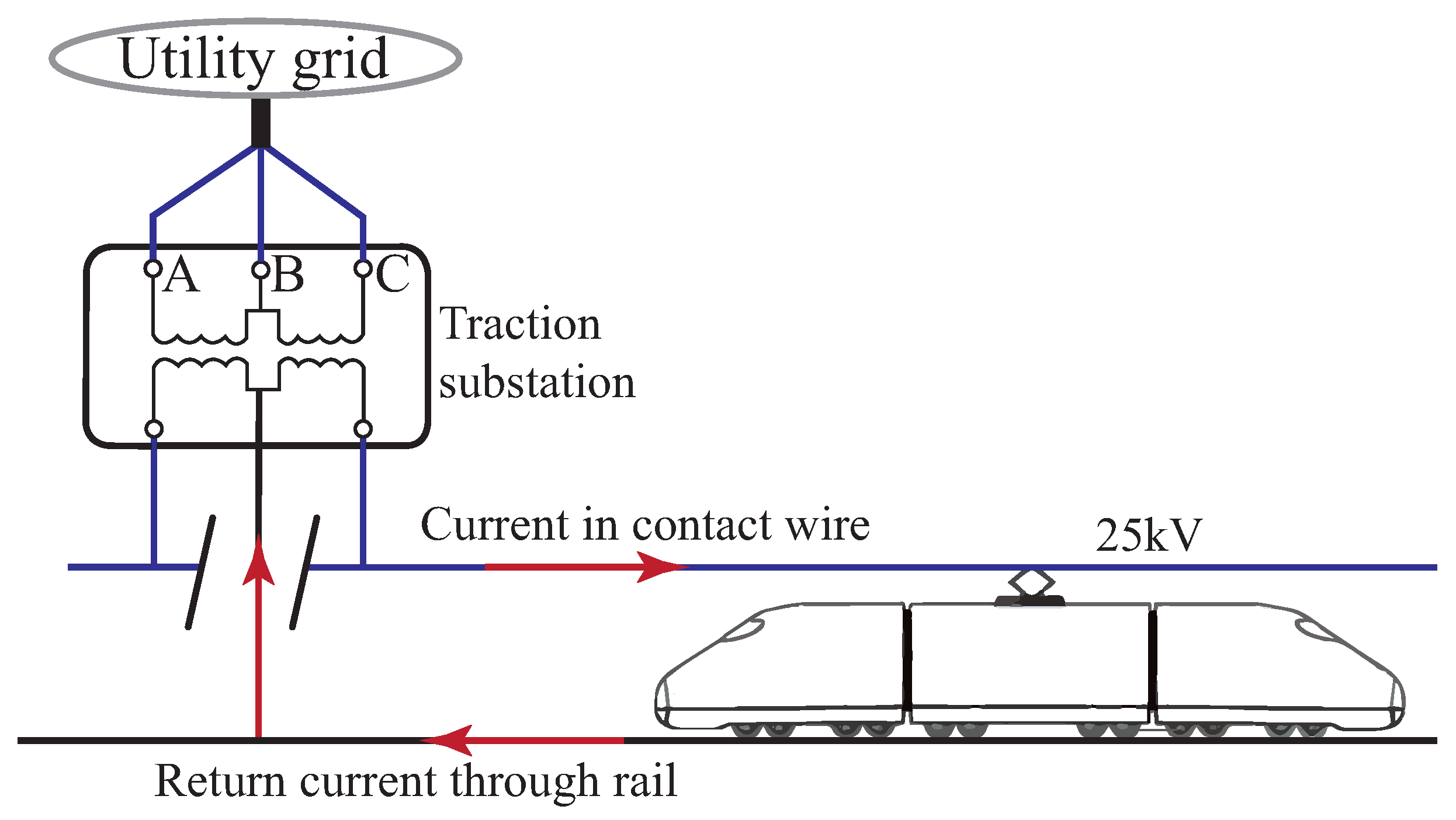
From a practical point of view, if an electric power transmission requires a return wire or the return current comes through the ground, it might be counted as an asymmetrical operation of the electric system. Thus, one of the major advantages of a symmetrically balanced system is that it does not require a return wire or a path because of the return current absence. There are, however, some other modern HV electric systems that operate inherently in asymmetrical (one-phase) mode. One example of such medium-voltage systems is utilized in railways, where electric locomotives draw power from an overhead single-phase power line, with the return current path provided by the rails. Such systems encompass both AC and DC types, with AC voltage levels (among others) of 15 kV at 16.7 Hz and 25 kV at 50 Hz. However, the 25 kV system is the most widely used, accounting for over 50% of all-electric traction systems worldwide [28]. Figure 9 schematically illustrates the powering system of an electric locomotive. The widespread adoption of 25 kV electrification is attributed to its optimal voltage level, which ensures efficient power distribution by aligning the electric load (locomotive) with the power supply. While increasing the voltage level may offer benefits, such as reducing the number of required substations and minimizing resistive losses ( I 2 R ), further increases are constrained by the growing requirements for insulation and clearance.
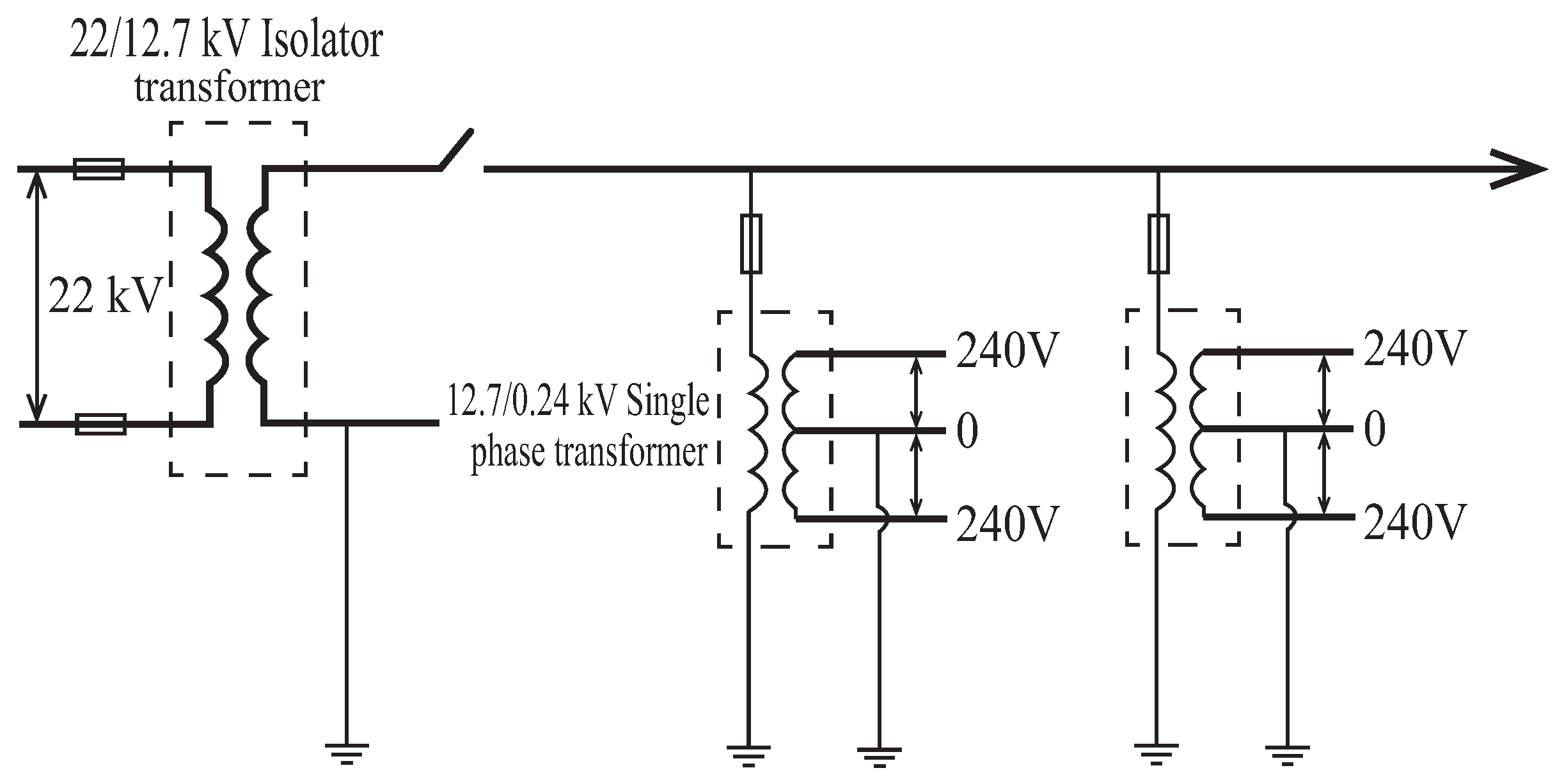
Another technology is the Single-Wire-Earth Return (SWER) electric system, which is used in distribution networks in rural areas, especially with distant low-load locations and sparse populations in some countries (African countries, New Zealand, Australia, the USA (Alaska)) [30]. First, it was implemented in New Zealand in 1920, with further growth there and in Australia. The modern SWER length in these countries is about 200 thousand kilometers [31]. The reasonableness comes from using only one wire, which requires less massive towers, and this, with design simplicity, increases construction speed. Together, all these factors reduce the capital cost of SWER systems. However, the limitations imposed by safety restrict the return current to 25 A at 19.1 kV, with the line rating at 480 kVA. Moreover, the earth resistivity limit, which has to be less than 1000 Ω /m, comes from the efficiency of the SWER line, which decreases dramatically when it has higher values. The other disadvantages are higher voltage drop and higher interference with telephone lines in comparison to the conventional three-phase systems [31,32].
Figure 10 shows a general SWER connecting scheme to a distribution line. One of the key devices in Figure 10 is the isolating transformer, which is used to feed the SWER system with lower voltage from a conventional three-phase medium-voltage distribution system. The other devices are used for protection purposes and earth return. The grounding of the one-phase HV transformer, however, has to be separate from the grounding of the LV transformer to avoid an electrical connection between HV and LV systems.
From 1930 to the 1950s in the USSR, “Two Wire-earth” (TWE) systems were commonly used to power three-phase loads in rural area power distribution networks (6–10 kV) with isolated neutral. One of the main reasons for the TWE powering spread was the material economy. Figure 11 represents a typical three-phase load powered by the TWE system when one of the phases’ current flows through the ground. TWE system is analyzed in [33] and shows acceptable (~15%) current asymmetry for a loaded TWE power line. However, the unloaded power line at 35 kV might produce large current asymmetry (~150%) due to the Ferranti effect. This asymmetry produces harmonics and so might interfere with communication lines. Thus, the author in [33] concludes that TWE systems have to be used at the lower voltage (6–10 kV) levels. The more recent article [34] states that TWE systems were superseded by usual three-phase systems due large impedance of the distribution substations’ grounding systems, which were not regulated at that time and had values about 4–5 Ω . However, at present, according to the regulations (Regulations for Electrical Installation, Russia), this value has to be 0.5 Ω , which makes the employment of TWE systems beneficial again for 6–35 kV power lines, by the authors’ conclusion. Furthermore, the current asymmetry can be minimized, too, by using filtering capacitors at the load side, as well as earth current if two parallel TWE power lines are used.
Figure 12 shows a summary and some features of different types of asymmetrical operation systems, categorized according to voltage levels. It demonstrates MV systems currently in use, TWE systems that have been discontinued, and HV/EHV systems for which theory is still under development.

3.4. Passive-Element Filters and Specific Transformers

According to the formulae provided in [35], passive-element filters can be used to suppress negative-sequence currents at the extremities of the power line. These filters consist of capacitive and inductive reactances connected in Y or Δ . In this review paper, Y-connected negative-sequence filters are considered because of the similarity of the principles with Δ connected filters.

3.5. Y-Connected Passive Filter

The Y-connected passive filters are shown in Figure 13. The reactances of the sending end filter are calculated using Formulae (7)–(9), and those of the receiving end filter using (10)–(12), [35].
X s a = 2 V s a I s a ( 2 )
X s b = 3 V s a I s a ( 2 ) + V s a I s a ( 2 )
X s c = 3 V s a I s a ( 2 ) + V s a I s a ( 2 )
where X s a , X s b , X s c are sending end filter phase reactances, V s a and I s a ( 2 ) are sending end a-phase voltage phasor and negative-sequence current phasor, respectively.
X r a = 2 V r a I r a ( 2 )
X r b = 3 V r a I r a ( 2 ) V r a I r a ( 2 )
X r c = 3 V r a I r a ( 2 ) V r a I r a ( 2 )
where X r a , X r b , X r c are receiving end filter phase reactances, V r a and I r a ( 2 ) are receiving end a-phase voltage phasor and negative-sequence current phasor, respectively.
These reactances can be represented in practice by reactive power compensation devices as proposed in [12].

3.6. Specific Transformers for Suppressing Zero-Sequence Currents

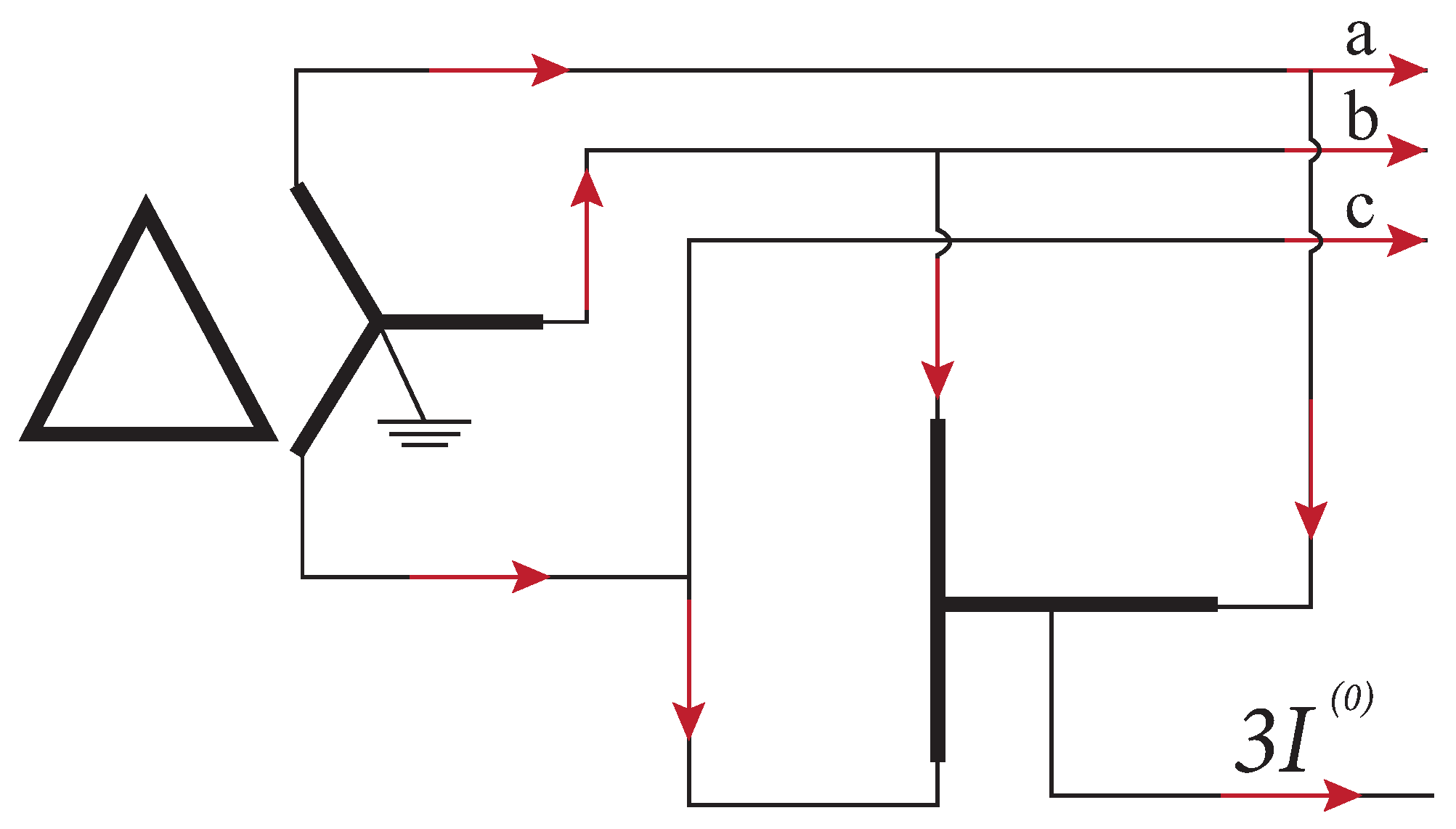
The zero-sequence currents can be filtered using grounding Zigzag, Δ -Y, or T-connected transformers at the extremities. In this paper, T-transformer is considered, and others can be found in [12]. Figure 14 shows a generic T-transformer connection to a power line for suppressing zero-sequence currents at one of the ends. As Delta-connected secondary winding of the transformer prevents zero-sequence current, I ( 0 ) , from circulating in it, they will be filtered out by the T-transformer and flow through the designated path.
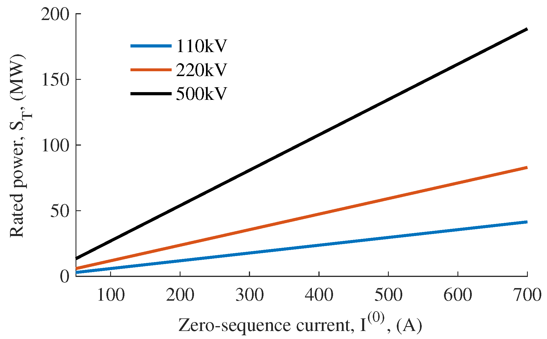
The rated power of the T-transformer can be found by
S T = 0.933 | V a n | | I ( 0 ) | .
where V a n is phase voltage and I ( 0 ) is zero-sequence current. Figure 15 shows power for different zero-sequence currents values calculated by Equation (13).
The disadvantage of such suppression method is the necessity of different power transformers for the different values of zero-sequence currents. Moreover, in normal operation, these transformers are not used.

3.7. Comparison of Passive Element with Power Electronic Filters

In opposite to negative- and zero-sequence currents suppression by passive elements/devices, when one device is used to compensate negative- and another zero-sequence currents, power electronic devices can be used to suppress both. In Table 1, the comparison is made between the passive-element filters and Power Electronic (PE) filters for providing asymmetric operation. Therefore, passive-element filters have the advantage of their location along the line [12]. PE filters have crucial advantages, such as the use of IBRs, which can be used to support asymmetric operation and high controllability.

4. Review of Latest Academic Literature on the Asymmetrical Operation Subject

The recently developed modular multilevel converter (MMC) offers significant advantages, including its applicability to high-voltage and high-power systems, as discussed in [37]. An MMC-based E-STATCOM is proposed in [38] for the stabilizing power output of solar power plants. Similarly, ref. [39] explores an MMC-based E-STATCOM and proposes a hybrid storage configuration, along with a control method for ancillary services, including the mitigation of negative-sequence currents. The shared DC-link among the storage systems in [39] ensures balanced current distribution across each leg of the converter. In [40], a fuzzy inference system controller is employed to mitigate voltage sags following symmetrical and asymmetrical faults using a D-STATCOM equipped with hydrogen fuel cells. The authors demonstrate the controller’s effectiveness and the system’s robustness. Furthermore, a multi-objective control strategy for a Battery Energy Storage System (BESS) using a cascaded H-bridge MMC is proposed in [41]. The study presents control methods aimed at reducing harmonics at the BESS output, therefore improving power quality. A comparative analysis of the performance of a Dynamic Voltage Restorer (DVR) and a D-STATCOM is provided in [42], focusing on scenarios with large single-phase and three-phase loads. The authors conclude that DVRs outperform D-STATCOMs in terms of voltage regulation, as DVRs are connected in series with the power line and directly influence the voltage, whereas D-STATCOMs, being connected in parallel, primarily control current injection. However, the asymmetric operation (as defined in this paper) is not investigated in the aforementioned studies, although voltage and current imbalances, as well as asymmetrical faults, are considered.
The following articles consider asymmetric operation, its implementation, and economic feasibility. In [13], the use of a spare conductor to replace a power line faulted phase is proposed and analyzed. This conductor can be automatically activated in the event of a phase-to-ground fault. While this solution has clear advantages, the costs associated with specialized towers and equipment render it impractical, particularly for extra-high voltage (EHV) and ultra-high voltage (UHV) long transmission lines. C. Todde et al. show in [5] the influence of the N − 1 criterion on the asymmetric operation of the power line. In addition, the costs of the compensation equipment to provide asymmetric operation are presented for the different voltage level power lines (400 kV, 500 kV, 735 kV) with 2, 3, and 4 parallel power lines in one corridor. The main conclusion, in [5], is that the more parallel power lines are used, the less the cost of compensation compared to the total electric transmission cost. Thus, it is 48% for two parallel lines at 500 kV and 30% for 4 parallel lines at the same voltage level. This gradation is expected due to the cost calculation of the compensation equipment made for the one-phase loss of one power line. This approach is reasonable because the probability of the second phase loss, when two-phase conductors are operational, is low [12]. A. Sana et al. show in [7] that considering three-phase power line separately in terms of phases allows the use of filtering techniques to provide balanced symmetry at the extremities of a power line. A simple probability analysis shown superficially in Section 2.3 and provided in [7] shows the increasing flexibility of a power line when/if asymmetrical operation is adopted. In particular, a few parallel working power lines are considered in [7]. In case of the loss of one of the phases of one of the lines, ref. [7] suggests employing series capacitors implemented beforehand into the working phases. This allows a decrease in the impedance of the power line after opening a phase conductor. However, the reactive power and sequence components of voltage and current at the extremities of a power line must be assessed. In addition, ref. [7] provides formulae to calculate series capacitance and shunt reactance for the asymmetric operation of N parallel power lines when one conductor open and pre-fault power flow is restored and the numerical example is demonstrated as well.
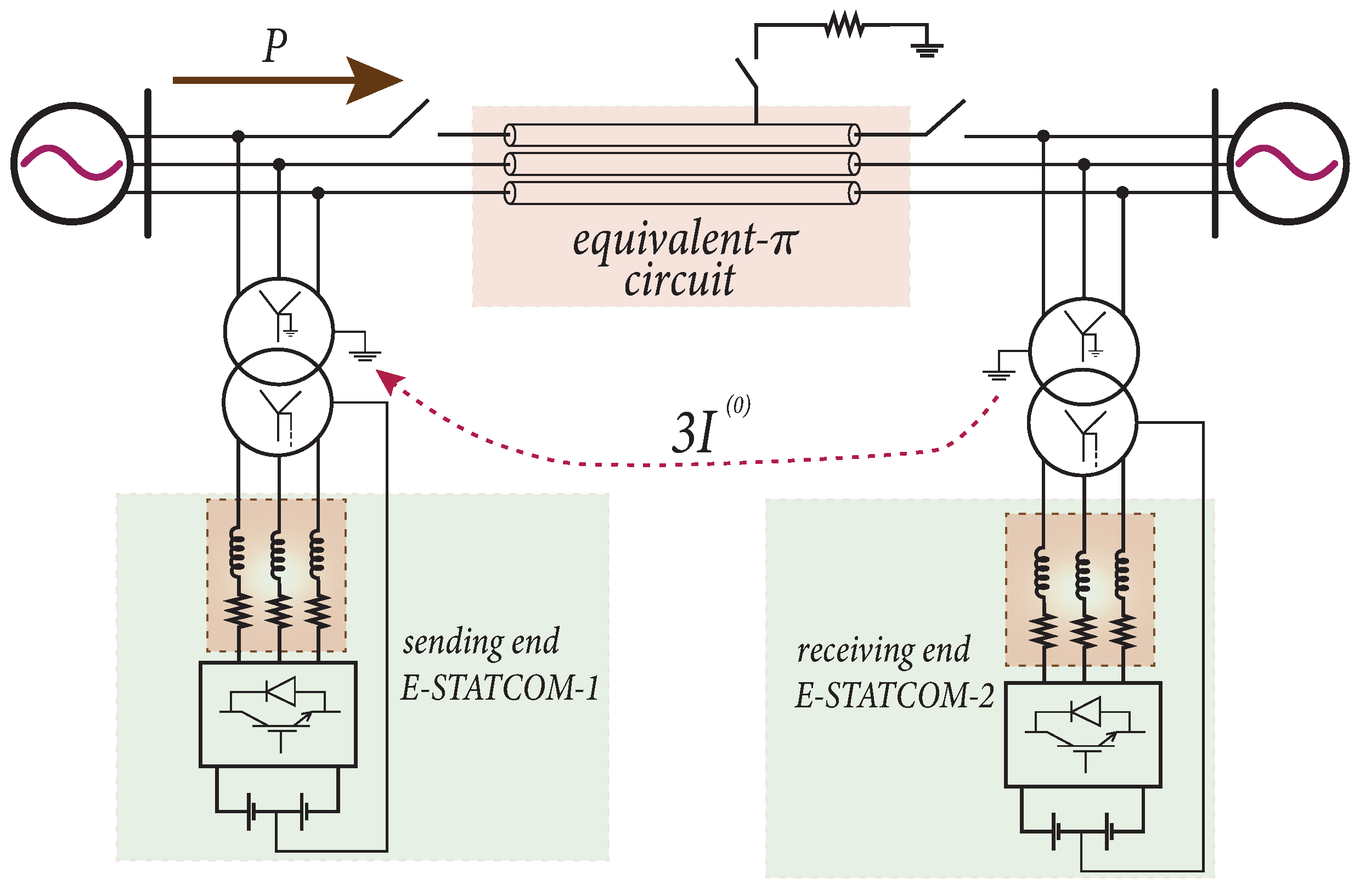
The single OPL asymmetric operation with one open phase analysis is shown in [6]. The asymmetric operation is realized by passive-element filters for the negative-sequence currents and T-transformer for filtering zero-sequence currents. It is suggested to connect neutrals of T-transformers of sending and receiving ends by shielding wire. The calculations, however, were made with the assumption that with an open phase, the voltages and currents will be the same as before the fault, whereas, in fact, they will change due to electromagnetic interaction discussed in Section 3.1. Mohamedi et al. in [43] compare asymmetric operation versus symmetric in terms of costs for 300 km long 400 kV 4 parallel power lines corridor when pre-fault power flow is restored and taken as SIL and by N − k criterion. The N − k criterion is a broaden form of N − 1 criterion when removing one of the elements (power line, transformer, etc.) will not lead to load shedding or generation relocation. In the symmetrical operation scenario in [43], one of the power lines is tripped off, so traditional balanced symmetry is not compromised, and, in asymmetrical operation, one phase of one of the power lines is open. For series compensation, the cost is taken as 20$ per kVAr, and for shunt compensation, it is 8$ per kVAr, according to [36]. Therefore, in all considered scenarios the costs for compensation of asymmetrical operation are higher than for symmetrical operation. Thus, in a multi-line corridor, asymmetric operation, in terms of economical point of view, might not be beneficial. In [44], a comparison is made of the investments in a corridor, similar to the analysis in [43], when operating after a phase-to-ground fault under both symmetrical and asymmetrical conditions. The authors show by making transient stability analysis that using Distributed Static Series Compensator (DSSC) modules is more beneficial in terms of the investment cost and the overall increasing controllability of the power flow effect. Assala et al. in [45] consider using Interphase Power Controller (IPC) 240 to support the asymmetrical operation of a 30 kV power line with pre-fault 3 MW power flow. For the simulations, the short power line model was used. Since compensating the negative- and zero-sequence currents does not restore the pre-fault power flow, PV generation is implemented to achieve this, and it is considered to be a separate scenario. Thus, it is shown that power transfer without a PV system and compensation is 2 MW and IPC before the fault is non-active. However, with the PV generation unit, the pre-fault 3 MW is achieved. The full pre-fault power flow restoration is desirable because the overall power flow in the grid will not change in this case, and other measures, such as load shedding and generation relocation, will not be necessary. Steva et al. in [46] consider symmetric and asymmetric operation (one and two phases open) of 225 kV 168 km long power line. For compensation of the power line in asymmetric operation, two IPCs 240 at the extremities and a STATCOM at the receiving end are used. Thus, the implementation of the STATCOM in asymmetric operation reduces the voltage magnitude difference between phases and so balances them, and, in addition, increases voltage magnitude at the receiving end making it closer to the nominal voltage level. Moreover, the use of STATCOM increases active power flow capability. It is also shown that the employment of IPC 240 allows for balancing voltages and currents at the power line extremities with two open phases. However, the main disadvantage is that the dual IPCs need centralized control, so communication between them is necessary. Asymmetric operation of the 500 kV 400 km long transmission power line is considered in [15]. The asymmetrical operation is provided using E-STATCOMs at the extremities of the power line. E-STATCOMs are represented by VSCs equipped with batteries, Figure 16. The use of energy sources is not necessary if the pre-fault power flow restoration is not the goal, however. The applied power line model is similar to that in Appendix A, so the sequence components are taken into account. To suppress sequence components, two-degrees-of-freedom internal-model-controllers are used. In the meantime, if the pre-fault power flow is desired to be restored, the energy storages at the sending and receiving ends consume and provide active power, respectively. Therefore, the energy storage at the sending end consumes excessive power as the power flow capability of the power line is decreased with an open phase, and receiving end battery storage provides the necessary amount. It is suggested, for the zero-sequence current path, to use the HVDC OPL approach described in Section 3.1 due to the current absence of the theory behind the use for this purpose of shielding wire.

5. Discussion

One of the crucial current challenges and/or research opportunities regarding asymmetrical operation is the lack of the OPL model, which can reflect the asymmetrical operation (with one/two open phases) and to what extent the consideration phases separately approach can be employed. Perhaps this approach might be appropriate for short power lines. However, for long power lines, where electromagnetic interaction is an unavoidable phenomenon, new models are needed to be developed. Moreover, although some of the early works [43,44] concluded that asymmetrical operation of a power line in a few parallel OPL corridors is less beneficial in terms of costs of the compensation equipment. There are cases in some National Power Systems (NPS) when electric power is transferred over long distances by one or two parallel OPLs. There tripping off the power line is more vulnerable. These cases need to be investigated to figure out the possible consequences. However, the positive fact regarding the implementation of the asymmetric operation is the growing share of IBRs in NPSs. Thus, one of the additional ancillary services provided by IBRs in the future might be providing asymmetric operation of the power line. Here, another question rises: the implications if asymmetrical operation is provided by wind or solar power plants. In this case, positive-sequence current at PCC can be controlled, yet these power plants have intermittent power output, which complicates the solutions.
When grounding electrodes are used for the zero-sequence current flow between compensators, factors such as safety (risk of hazardous ground potentials), soil acidification, and electrode corrosion must be taken into account. So far, monopolar and bipolar HVDC OPLs have been using earth-return DC, which may provide a pattern for the case of AC systems. However, AC systems may impose more challenges in safety than DC systems. Additionally, if ground currents circulate for an extended period of time, the current flowing through the earth triggers an electrolysis process, which in in the long term may lead to unsuitability of soil in terms of agricultural use [47]. Another issue to consider is the natural corrosion of earth electrodes, which would trigger electrode degradation over time. References mention that electrodes would degrade about 20 pounds per DC ampere if they are used continuously for a year [17]. In asymmetrical systems, the zero-sequence current would be AC, which has the potential to accelerate electrode degradation. Because of the aforementioned issues, a recommendation would be to limit the time a system operates in an asymmetrical mode, maybe for minutes or hours until backup generation can be brought online or the location of the faulted line has been found. The use of passive elements to enable the asymmetrical operation of an energy corridor may not be economically viable given the level of investment needed and the fact that such passive elements will be used very sporadically. However, if active elements are already present in the transmission line (for example, STATCOMs to regulate voltage levels), then such elements could be used to provide asymmetrical compensation without the need for extra investment.
Lastly, due to the historical philosophy of using three-phase symmetrical, balanced voltages and currents, the protection schemes have to be adapted to allow power flow in a line operating asymmetrically. This may call for adaptive protection schemes, giving researchers the opportunity to innovate on this topic.

6. Conclusions

This review revised the current challenges of power networks and the arguments to consider asymmetrical operation as an option to increase the reliability and security of power supply. In general, this review demonstrates that faults in long transmission lines and their eventual disconnection are negative factors in the renewable energy integration plans of major countries. The opportunity to retain most of the power flow after a fault, using the asymmetrical operation of transmission lines, is extremely useful to improve the reliability and security of supply in many countries. From a methodological perspective, this paper demonstrates that there exist several historical methods to operate electricity corridors asymmetrically, some of which are still in use today. In terms of modifications to symmetrical systems to allow asymmetrical operation, this review showed the work done by pioneers in the subject but also highlighted the limitations of their methodologies and the places where more research is needed. For example, the electromagnetic interactions of healthy lines with disconnected ones. Next, this review demonstrated and listed research currently underway in the control of inverters that has applications for asymmetrical operation of power systems. Finally, this review demonstrates that operational experience and standards from other types of power transfer systems (HVDC) can be adapted, and their methods applied to asymmetrical operation. The union of historical methodologies, pioneering work, and current research has the potential to initiate a new line of research in power systems where asymmetrical operation is an integral part of the different methodologies applied to improve the security of supply, enabling greater penetration of renewables in modern power systems. Researchers interested in the asymmetrical operation topic have vast opportunities to contribute in the realms of FACTS, STATCOMs, active power filter controllers, ground electrodes, and electromagnetic interactions.

Funding

This research was funded by Center for International Programs ‘Bolashaq’ grant number 5536.

Acknowledgments

The authors would like to acknowledge CIP “Bolashaq” for funding this research, and also Abdou Sana from Lightsource BP, and Beckzhan Mukatov the former head of the Kazakhstan SO control center for their valuable input and support to this research.

Conflicts of Interest

The authors declare no conflicts of interest.

Abbreviations

The following abbreviations are used in this manuscript:
APFActive Power Filter
DGDistributed Generation
DSSCDistributed Static Series Compensator
EHVExtra-High Voltage
FACTSFlexible Alternating Current Transmission System
IBRInverter-Based Resources
IPCInterphase Power Controller
NPSNational Power System
OPLOverhead Power Line
PCCPoint of Common Coupling
PPPower Plant
RESRenewable Energy Sources
SILSurge Impedance Loading
SWERSingle-Wire-Earth Return
UHVUltra-High Voltage

Appendix A. Generic Three-Phase Power Line Model
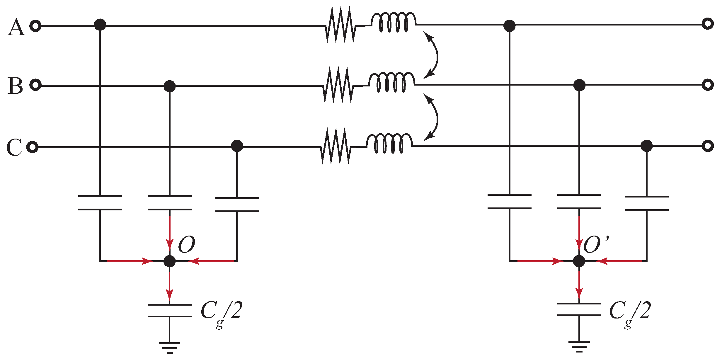
If electromagnetic waves which persist in power lines are not under consideration, a power line can be described by Figure A1.
Figure A1. Power line mode in sequence-components [48].
Energies 17 05021 g0a1

References

  1. Whelan, M.; Rockwell, S.; Blalock, T. Great Barrington 1886: Inspiring an Industry Toward AC Power. Available online: https://edisontechcenter.org/GreatBarrington.html (accessed on 28 August 2024).
  2. Harnessing Niagara Falls: The Adams Power Station. The Most Famous of Early Hydroelectric Power Stations. Available online: https://edisontechcenter.org/Niagara.htm#:~:text=President%20Adams%20and%20Forbes%of,phase%2C%four-wire%2Dgenerators (accessed on 28 August 2024).
  3. IEA. Renewables 2023; Licence: CC BY 4.0; IEA: Paris, France, 2024. [Google Scholar]
  4. Meserve, B.E. Fundamental Concepts of Algebra; Dover Publications: Mineola, NY, USA, 1982; originally published: Cambridge, MA, USA, in 1953. [Google Scholar]
  5. Todde, C.; Marceau, R.J.; McGillis, D.; Lefebvre, S.; Sana, A.R. An investigation into the compensation of asymmetric systems. In Proceedings of the Engineering Solutions for the Next Millennium. 1999 IEEE Canadian Conference on Electrical and Computer Engineering (Cat. No. 99TH8411), Edmonton, AB, Canada, 9–12 May 1999; Volume 2, pp. 1187–1190. [Google Scholar]
  6. Sana, A.R.; McGillis, D.; Marccau, R.; Do, X.D.; Olivier, G. Asymmetrical operation of corridor with one single line. In Proceedings of the 2000 Canadian Conference on Electrical and Computer Engineering. Conference Proceedings. Navigating to a New Era (Cat. No. 00TH8492), Halifax, NS, Canada, 7–10 May 2000; Volume 2, pp. 936–940. [Google Scholar]
  7. Sana, A.R.; Marceau, R.J.; McGillis, D.T.; Todde, C.; Do, X.D. On the asymmetrical operation of transmission systems. In Proceedings of the CIGRE Symposium on Working Plant and Systems Harder, London, UK, 7–9 June 1999; pp. 400.011–400.016, ARRAY(0x5587225ee388). [Google Scholar]
  8. Marceau, R.; McGillis, D.; Sana, A. The role of asymmetric operation in enhancing the flexibility of power system operation. In Proceedings of the CCECE 2003—Canadian Conference on Electrical and Computer Engineering Toward a Caring and Humane Technology (Cat. No.03CH37436), Montreal, QC, Canada, 4–7 May 2003; Volume 1, pp. 509–514. [Google Scholar] [CrossRef]
  9. Belyakov, N.N.; Volchek, V.L.; Ilyinichin, V.V.; Losev, S.B.; Lyskov, Y.I.; Novella, V.N.; Rashkes, V.S.; Strelkov, V.M.; Fokin, G.G.; Khoroshev, M.I. Application of Single-Phase Autoreclosing in a Complex EHV Network Containing 1200 kV Transmission Lines. In Protection and Automation (B5) Committee Session Materials; CIGRE: Paris, France, 1990; pp. 34–207. [Google Scholar]
  10. Kazakhstan Government. Concept on Transition towards Green Economy until 2050. 2013. Available online: https://policy.asiapacificenergy.org/sites/default/files/Concept%20on%20Transition%20towards%20Green%20Economy%20until%202050%20%28EN%29.pdf (accessed on 10 September 2024).
  11. Pruski, P.; Paszek, S. Analysis of transient waveforms in a power system at asymmetrical short-circuits. Prz. Elektrotech. 2020, 2, 26–29. [Google Scholar] [CrossRef]
  12. Marceau, R.J.; McGillis, D.T.; Sana, A.R. Asymmetric Operation of AC Power Transmission Systems: The Key to Optimizing Power System Reliability and Economics; Presses inter Polytechnique: Montréal, QC, Canada, 2006. [Google Scholar]
  13. Sana, A.R.; Marceau, R.; Todde, C.; Do, D.; Mahseredjian, J.; Joos, G. The exploitation of asymmetry in electric power transmission networks. In Proceedings of the Conference Proceedings. IEEE Canadian Conference on Electrical and Computer Engineering (Cat. No.98TH8341), Waterloo, ON, Canada, 25–28 May 1998; Volume 2, pp. 485–488. [Google Scholar] [CrossRef]
  14. Glover, J.D. Power System Analysis & Design, 7th ed.; Cengage: Boston, MA, USA, 2023. [Google Scholar]
  15. Berdygozhin, A.; Pepper, B.; Campos-Gaona, D. Asymmetric Operation of Power Lines by Using E-STATCOM and Internal Model Controllers. In Proceedings of the 2024 IEEE 15th International Symposium on Power Electronics for Distributed Generation Systems (PEDG), Luxembourg, 23–26 June 2024; pp. 1–6. [Google Scholar] [CrossRef]
  16. EPRI. HVDC Ground Electrode Overview; Technical report; Electric Power Research Institute (EPRI): Palo Alto, CA, USA, 2010. [Google Scholar]
  17. Holt, R.J.; Dabkowski, J.; Hauth, R.L. HVDC Power Transmission Electrode Siting and Design; Technical report; New England Power Service Company: Westborough, MA, USA, 1997. [Google Scholar]
  18. CIGRÉ. General Guidelines for HVDC Electrode Design; Tech. Brochure WG B4.61; CIGRÉ: Paris, France, 2017. [Google Scholar]
  19. Mishra, M.K. Power Quality in Power Distribution Systems: Concepts and Applications; CRC Press: Boca Raton, FL, USA, 2023. [Google Scholar]
  20. Yin, F.; Zhao, P.; Wang, Y.; Li, Z.; Wang, Y.; Xiao, X. Coordinated central and local voltage control in low voltage distribution network with photovoltaic generation. In Proceedings of the 2019 IEEE 3rd International Electrical and Energy Conference (CIEEC), Beijing, China, 7–9 September 2019; pp. 298–302. [Google Scholar] [CrossRef]
  21. Papachristou, A.C.; Awad, A.S.A.; Turcotte, D.; Wong, S.; Prieur, A. Impact of DG on Voltage Unbalance in Canadian Benchmark Rural Distribution Networks. In Proceedings of the 2018 IEEE Electrical Power and Energy Conference (EPEC), Toronto, ON, Canada, 10–11 October 2018; pp. 1–6. [Google Scholar] [CrossRef]
  22. Akagi, H. Instantaneous Power Theory and Applications to Power Conditioning; IEEE Press Series on Power Engineering; Wiley: Hoboken, NJ, USA; IEEE Press: Piscataway, NJ, USA, 2007. [Google Scholar]
  23. Campos-Gaona, D.; Peña-Alzola, R.; Monroy-Morales, J.L.; Ordonez, M.; Anaya-Lara, O.; Leithead, W.E. Fast Selective Harmonic Mitigation in Multifunctional Inverters Using Internal Model Controllers and Synchronous Reference Frames. IEEE Trans. Ind. Electron. 2017, 64, 6338–6349. [Google Scholar] [CrossRef]
  24. Khoshooei, A.; Moghani, J.S.; Candela, I.; Rodriguez, P. Control of D-STATCOM During Unbalanced Grid Faults Based on DC Voltage Oscillations and Peak Current Limitations. IEEE Trans. Ind. Appl. 2018, 54, 1680–1690. [Google Scholar] [CrossRef]
  25. Merritt, N.R.; Chakraborty, C.; Bajpai, P. An E-STATCOM Based Solution for Smoothing Photovoltaic and Wind Power Fluctuations In a Microgrid Under Unbalanced Conditions. IEEE Trans. Power Syst. 2022, 37, 1482–1494. [Google Scholar] [CrossRef]
  26. Edison, O.E. Regulation of Open Delta Connected Transformers; The University of Nebraska-Lincoln: Lincoln, NE, USA, 1915. [Google Scholar]
  27. Roux, G.P. Delta-Cross Connections of Transformers. Trans. Am. Inst. Electr. Eng. 1915, 34, 2141–2155. [Google Scholar] [CrossRef]
  28. Brenna, M.; Foiadelli, F.; Zaninelli, D. Electrical Railway Transportation Systems, 1st ed.; IEEE Press Series on Power Engineering; Wiley: Hoboken, NJ, USA, 2018. [Google Scholar]
  29. Chen, M.; Liu, S.; Zhu, J.; Xie, C.; Tian, H.; Li, J. Effects and Characteristics of AC Interference on Parallel Underground Pipelines Caused by an AC Electrified Railway. Energies 2018, 11, 2255. [Google Scholar] [CrossRef]
  30. Samra, B.S. An Analysis of Single Wire Earth Return (SWER) System for Rural Electrification; University of Missouri: Rolla, MO, USA, 1972. [Google Scholar]
  31. Karhammar, R.; Sanghvi, A.; Fernstrom, E.; Aissa, M.; Arthur, J.; Tulloch, J.; Davies, I.; Bergman, S.; Mathur, S. Sub-Saharan Africa: Introducing Low-Cost Methods in Electricity Distribution Networks; ESMAP Technical Paper 104; ESMAP: Washington, DC, USA, 2006. [Google Scholar]
  32. Da Silva, I. The Use of Single Wire Earth Return (SWER) as a Potential Solution to Reduce the Cost of Rural Electrification in Uganda. 2001. Available online: https://www.researchgate.net/profile/Izael-Da-Silva/publication/236216354_The_use_of_single_wire_earth_return_SWER_as_a_potential_solution_to_reduce_the_cost_of_rural_electrification_in_Uganda/links/00b7d539b0c84a40bc000000/The-use-of-single-wire-earth-return-SWER-as-a-potential-solution-to-reduce-the-cost-of-rural-electrification-in-Uganda.pdf (accessed on 5 June 2024).
  33. Benar, P.P. Electric power transmission «two wires—earth». Elektrichestvo 1933, 13–20. (In Russian) [Google Scholar]
  34. Buryanina, N.; Korolyuk, Y.; Lesnykh, E. Using “Two Wires-Earth” Power Transmission Lines. Proc. Irkutsk State Tech. Univ. 2017, 21, 91–99. [Google Scholar] [CrossRef]
  35. Bouchard, R.P.; Olivier, G. Electrotechnique; Presses Inter Polytechnique: Montréal, QC, Canada, 1999. [Google Scholar]
  36. Mathur, R.M. Thyristor-Based FACTS Controllers for Electrical Transmission Systems/[internet Resource]; IEEE Press Series on Power Engineering; IEEE: Piscataway, NJ, USA, 2002. [Google Scholar]
  37. Dekka, A.; Wu, B.; Fuentes, R.L.; Perez, M.; Zargari, N.R. Evolution of Topologies, Modeling, Control Schemes, and Applications of Modular Multilevel Converters. IEEE J. Emerg. Sel. Top. Power Electron. 2017, 5, 1631–1656. [Google Scholar] [CrossRef]
  38. Ch, A.B.; Maiti, S. Modular multilevel E-STATCOM considering distributed energy storage at the dc link. In Proceedings of the 2016 IEEE 7th Power India International Conference (PIICON), Bikaner, India, 25–27 November 2016; pp. 1–6. [Google Scholar] [CrossRef]
  39. Bharadwaj, A.; Maiti, S. 18—Multilevel converter-based STATCOM with hybrid storage system. In Emerging Trends in Energy Storage Systems and Industrial Applications; Prabhansu, Kumar, N., Eds.; Academic Press: Cambridge, MA, USA, 2023; pp. 521–534. [Google Scholar] [CrossRef]
  40. Kilic, H.; Asker, M.E.; Haydaroglu, C. Enhancing power system reliability: Hydrogen fuel cell-integrated D-STATCOM for voltage sag mitigation. Int. J. Hydrogen Energy 2024, 75, 557–566. [Google Scholar] [CrossRef]
  41. Eroğlu, F.; Kurtoğlu, M.; Eren, A.; Vural, A.M. Multi-objective control strategy for multilevel converter based battery D-STATCOM with power quality improvement. Appl. Energy 2023, 341, 121091. [Google Scholar] [CrossRef]
  42. Kamarposhti, M.A.; Colak, I.; Thounthong, P.; Eguchi, K. Modeling and Simulation of DVR and D-STATCOM in Presence of Wind Energy System. Comput. Mater. Contin. 2022, 74, 4547–4570. [Google Scholar] [CrossRef]
  43. Mohamedi, R.; Lefebvre, S.; Ba, A.O.; Houle, A. Comparative Study of the Symmetric and Asymmetric Approaches to Increase Power Transfer Capacity of a Corridor. In Proceedings of the 2007 iREP Symposium—Bulk Power System Dynamics and Control—VII. Revitalizing Operational Reliability, Charleston, SC, USA, 19–24 August 2007; pp. 1–7. [Google Scholar] [CrossRef]
  44. Mohamedi, R.; Lefebvre, S.; Ba, A.O.; Houle, A. Increasing the Transfer Capacity of a Corridor through Power Flow Control. In Proceedings of the 2007 IEEE Canada Electrical Power Conference, Montreal, QC, Canada, 25–26 October 2007; pp. 507–513. [Google Scholar] [CrossRef]
  45. Mougnol Assala, G.R.; Mandeng, J.J.; Kom, C.H.; Mbihi, J. Grid-tied PV system-based power compensation of a grid equipped with dual interphase power controllers (IPC) 240 with three branches: Case of a short transmission line. Energy Syst. 2023, 1–21. [Google Scholar] [CrossRef]
  46. Steva, K.C.C.; Ghislain, M.M.; Joseph, K.K.; Jeannot, B.G.; Leandre, N.N. Contribution to Asymmetrical Compensation through Parallel Controllers of FACTS (STATCOM)—IPC 240 Dual for a Power Transmission Line. World J. Eng. Technol. 2022, 11, 20–40. [Google Scholar] [CrossRef]
  47. Yadav, D.S.; Jaiswal, B.; Gautam, M.; Agrawal, M. Soil Acidification and Its Impact on Plants; Springer: Berlin/Heidelberg, Germany, 2020; pp. 1–26. [Google Scholar]
  48. MathWorks. Three-Phase PI Section Line. Available online: https://uk.mathworks.com/help/sps/powersys/ref/threephasepisectionline.html (accessed on 26 July 2024).
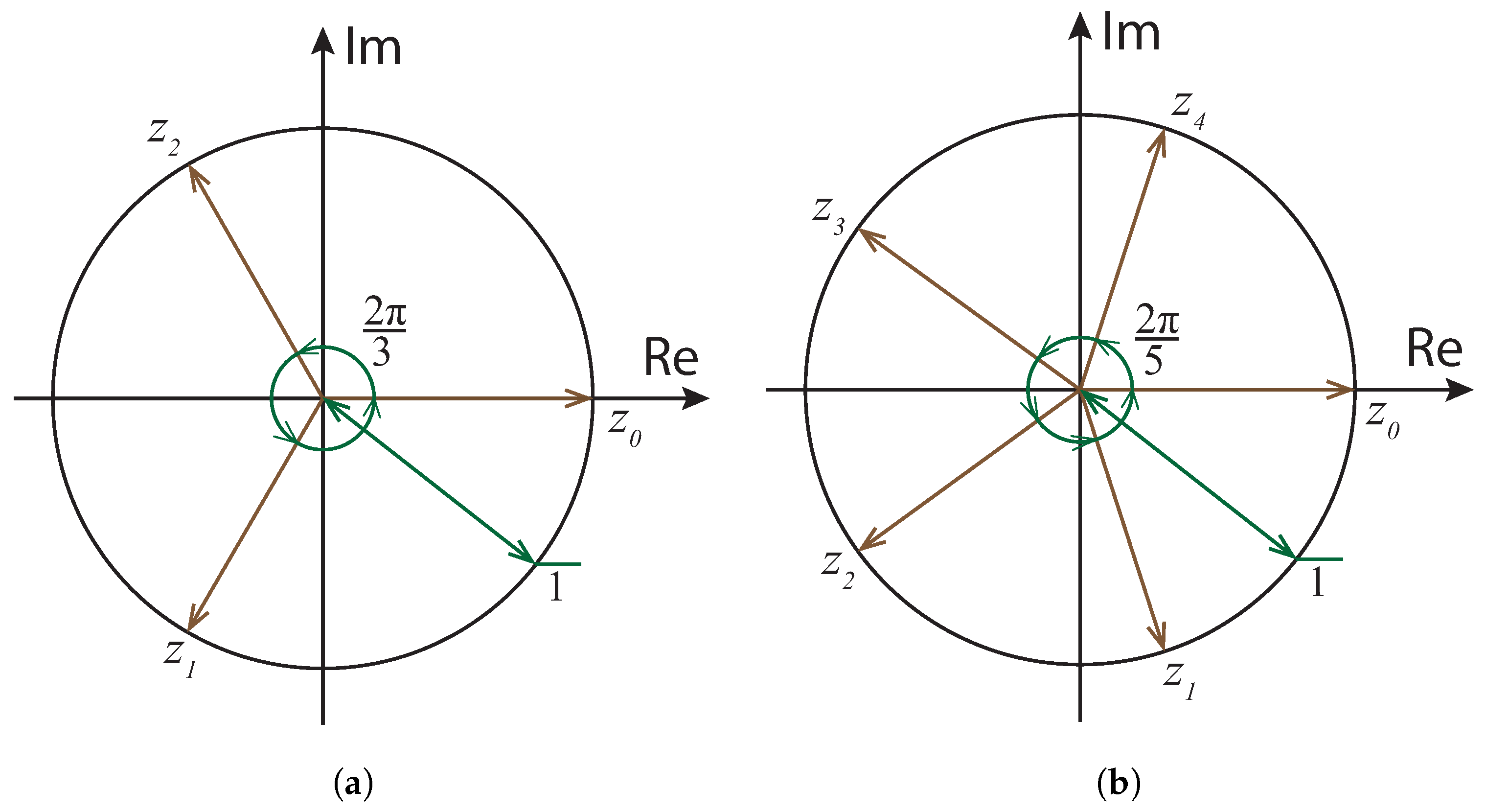
Figure 1. Balanced symmetrical polyphase systems’ (unity length) phasors representation on the complex plain. (a) Roots of unity for 3 phasors ( n = 3 ); (b) Roots of unity for 5 phasors ( n = 5 ).
Energies 17 05021 g001
Figure 2. Simplified North-South electric power transmission network of Kazakhstan National Power System (PP—power plants, the system operator divides the NPS into three zones).
Energies 17 05021 g002
Figure 3. Principle representation of the power line asymmetric operation using filters at the extremities.
Energies 17 05021 g003
Figure 4. Electric power transmission via power lines connected in series and its one element or one power line with an open phase.
Energies 17 05021 g004
Figure 5. Logic schemes of probability of the power line tripping [13]: (a) Symmetrical operation, (b) Asymmetrical operation.
Energies 17 05021 g005
Figure 6. Successful OPL probability in symmetric and asymmetric operation.
Energies 17 05021 g006
Figure 7. One-phase AC voltage source connected to the distribution line.
Energies 17 05021 g007
Figure 8. A power line asymmetric operation after a short circuit supported by Delta-connected transformers at the extremities.
Energies 17 05021 g008
Figure 9. Electric locomotive powering schematic (adapted from [29]).
Energies 17 05021 g009
Figure 10. Typical SWER powering configuration.
Energies 17 05021 g010
Figure 11. Typical “two wire-earth” (TWE) configuration.
Energies 17 05021 g011
Figure 12. Asymmetrical operation systems summarizing diagram.
Energies 17 05021 g012
Figure 13. Y-connected passive filters at the power line extremities.
Energies 17 05021 g013
Figure 14. Connection of T-transformer for zero-sequence filtering (adapted from [12]).
Energies 17 05021 g014
Figure 15. Power ratings of T-transformers for different voltage levels.
Energies 17 05021 g015
Figure 16. A power line’s asymmetric operation after a short circuit, supported by E-STATCOMs at the extremities.
Energies 17 05021 g016
Table 1. Comparison of Passive Element with Power Electronic Filters.
Passive-Element FiltersPower Electronic Filters
ProsCan be located anywhere along the lineIBRs can be used in fault conditions
Flexible to the power flow changes
High controllability
ConsLow controllability of controllable shunt reactors [36]
Different devices for negative- and zero-sequence current components
Complicated implementation along the line
Disclaimer/Publisher’s Note: The statements, opinions and data contained in all publications are solely those of the individual author(s) and contributor(s) and not of MDPI and/or the editor(s). MDPI and/or the editor(s) disclaim responsibility for any injury to people or property resulting from any ideas, methods, instructions or products referred to in the content.